FUSELAGE. An aircraft s main body section that holds crew and passengers or cargo It is derived from the French word Fusele Spindle shaped
|
|
|
- Kathlyn Page
- 6 years ago
- Views:
Transcription
1 DAY 2
2 FUSELAGE

3 FUSELAGE An aircraft s main body section that holds crew and passengers or cargo It is derived from the French word Fusele Spindle shaped
4 FUSELAGE
5 FUSELAGE ASSEMBLAGE

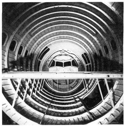
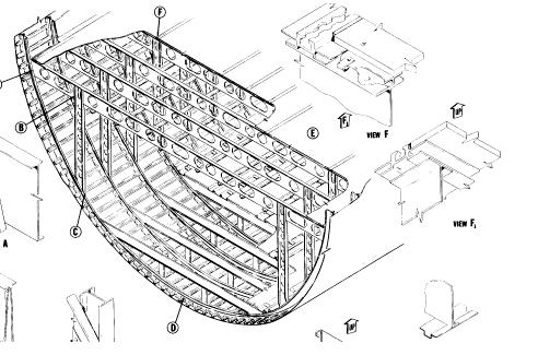
6 TYPES OF FUSELAGE STRUCTURE Box truss type The structural elements resemble those of a bridge, with emphasis on using linked triangular elements. The aerodynamic shape is completed by additional elements called formers and stringers and is then covered with fabric and painted Monocoque the exterior surface of the fuselage is also the primary structure Semi-monocoque A series of frames in the shape of the fuselage cross sections are held in position on a rigid fixture, or jig. These frames are then joined with lightweight longitudinal elements called stringers. These are in turn covered with a skin of sheet aluminum, attached by riveting or by bonding with special adhesives
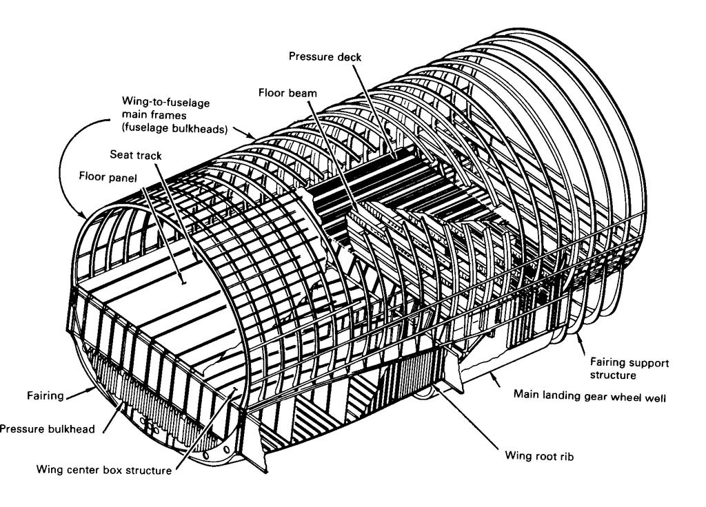
7 SEMI-MONOCOQUE FUSELAGE Semi-monocoque fuselage structure consists of Longerons / stringers (Longitudinal members) Longerons carries the bending load as axial load Stringers also carry axial load Stringers stabilize the skin Framing (Transverse members) Provide the shape to the fuselage Reduce the stringer length thus avoiding overall instability Skin Carries the shear load from the cabin pressure, external transverse and torsional loads Bulkheads Bulkheads are provided at concentrated loading regions such as wing attachments, tail attachments and landing gear locations
8 SEMI-MONOCOQUE FUSELAGE
9 COMPARISON OF FUSELAGE & WING STRUCTURE WINGS FUSELAGE Spar caps carry axial loads induced by bending Longerons and stringers carry axial load induced by bending Shear loads are resisted by spar web Transverse shear loads are carried by skin Rib design is influenced by local air loads Fuselage frames are influenced by concentrated loads Wing skin thickness is more compared to fuselage skin Because of the curvature, the fuselage skins under compressive and shear load are more stable Less skin thickness is used External pressure loads are more on the wing skin External pressure loads are very less on the fuselage skin
10 FUSELAGE CONFIGURATION AERODYNAMIC SMOOTHNESS PASSENGER REQUIREMENT LANDING GEAR REQUIREMENT
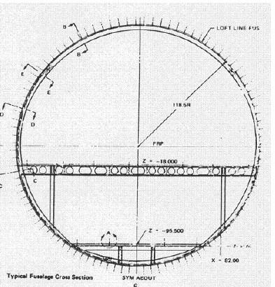
11 TYPICAL CROSS SECTION
12 TYPICAL FRAMES Former frame Pitch = 20 Bulkhead frame
13 STRINGER FRAME CONNECTION Stringer and frame are connected through clips Stringer clips Transfer the skin panel normal pressure loads to frame Helps break up of effective column length Provides some degree of compressive strength at the inner cap Acts as frame web panel stiffener
14 FLOOR BEAMS
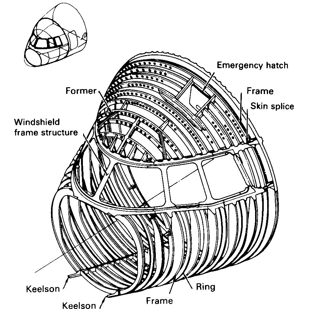
15 COCKPIT

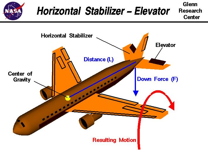
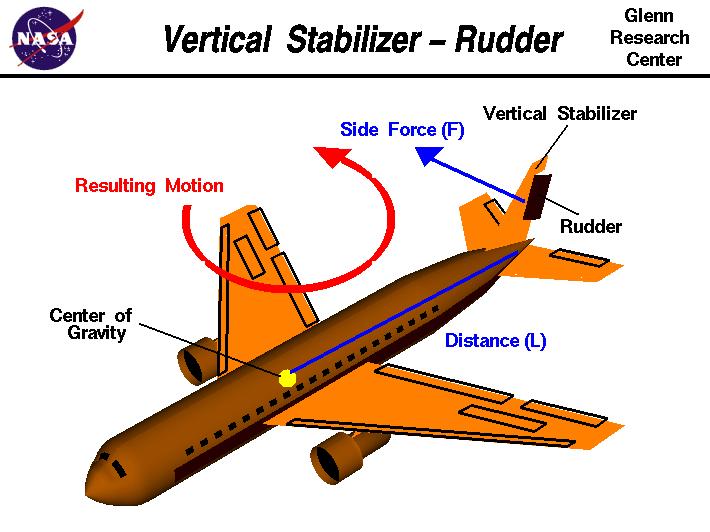
16 EMPENNAGE Empennage is the tail portion of an aircraft The empennage gives stability to the aircraft and controls the pitch and yaw. In simple terms the empennage may be compared to the feathers of an arrow, colloquially; "Tail Feathers" Structurally, the empennage consists of the entire tail assembly, including the fin, tail plane and the part of the fuselage to which these are attached. Vertical stabilizer Rudder Elevator Fuselage Horizontal stabilizer
17 LANDING GEAR Two landing gears are available Nose landing gear Main landing gear
18 MAIN LANDING GEAR
19 AIRCRAFT LOADS
20 LOADS Ground loads Landing Transportation Taxiing Air loads Manoeuvre Gust
21 BASIC FLIGHT LOADS Positive high angle of attack Normal force (N) produces compressive stress on the wing upper portion Moments from the chord wise force (C) produces compressive stress on the leading edge Critical for compressive stresses in upper forward region and tensile stresses in lower aft of the wing Positive low angle of attack Chord wise force (C) is the largest force acting aft on the wing Wing bending moment produce maximum compressive stresses in upper front spar flange and maximum tensile stresses in the lower front spar flange Negative high angle of attack Loads are smaller compared to positive high angle of attack Wing bending moment produce maximum compressive stresses in lower forward region and maximum tensile stresses in the upper aft region Negative low angle of attack Chord wise force (C) is the largest force acting aft on the wing Maximum compressive bending stresses in lower aft region and tensile stresses in the upper forward region of the wing
22 AIRCRAFT LOADS Loads and forces applied on the aircraft structural components to establish the strength level Air pressure Inertial loads Landing loads
23 DESIGN LOADS LIMIT LOAD: Maximum load anticipated in aircraft service life time Load aircraft structure should withstand without causing any permanent deformation ULTIMATE LOAD = 1.5 x LIMIT LOAD LOADS SPECIFIED BY THE LOAD GROUP IS ALWAYS THE LIMIT LOAD
24 SAFETY FACTOR SAFETY FACTOR = ULTIMATE LOAD /LIMIT LOAD SAFETY FACTOR IS PROVIDED FOR THE FOLLOWING REASONS UNCERTAINTIES IN LOADS INACCURACIES IN STRUCTURAL ANALYSIS VARIATIONS IN STRENGTH PROPERTIES OF MATERIALS DETORIATION DURING SERVICE LIFE VARIATION IN FABRICATION IN NOMINALLY IDENTICAL COMPONENTS
25 AIRSPEED Airspeed (AS) Speed of the aircraft relative to air Indicated Airspeed (IAS) Speed of an aircraft as shown on its pitot static airspeed indicator True Airspeed (TAS) Physical speed of the aircraft relative to the air surrounding the aircraft Vt = V g V w Equivalent Airspeed (EAS) Speed at sea level that would produce the same incompressible dynamic pressure as the true airspeed at the altitude at which the vehicle is flying Vi = 1 + M + M + M Ve
26 LIMITING AIRSPEED Limiting Airspeed Speed of the aircraft up to which the structure may not undergo any permanent damage Crossing the limiting airspeed may cause Critical gust Destructive flutter Aileron reversal Wing or surface divergence Stability and control problems Damaging buffets

27 FORCES ON AN AIRCRAFT
28 LIFT Lift is a mechanical force generated by solid objects as they move through a fluid Lift is the sum of all the fluid dynamic forces on a body perpendicular to the direction of the external flow approaching that body Lift generated on an airfoil depends on Angle of attack Speed of the air flow Total area Density of air 1 2 L = ρv SC L 2
29 AIRFOIL Airfoil is the shape of a wing or blade (of a propeller, rotor or turbine) or sail as seen in cross-section Airfoils are Symmetric (Mean camber line coincides with chord line) Cambered

30 AIRFOIL TERMINOLOGY Leading edge Trailing edge Leading edge is the front edge of the airfoil Trailing edge is the back edge of the airfoil The mean camber line is a line drawn half way between the upper and lower surfaces. The chord line is a straight line connecting the leading and trailing edges of the airfoil, at the ends of the mean camber line. The chord is the distance between the leading edge and trailing edge The maximum thickness and the location of maximum thickness are expressed as a percentage of the chord Camber is the asymmetry between the top and bottom curves of an aerofoil
31 PRESSURE VARIATION F = pn A = pn da Γ
 1 1 0 0 NOTE: Changing either the direction or speed of the flow generates a")
32 LIFT GENERATION Lift is a force generated by turning a moving fluid Force = mass x acceleration (F=ma) m(v V ) F = Force = mass x Change in velocity (t t ) NOTE: Changing either the direction or speed of the flow generates a force
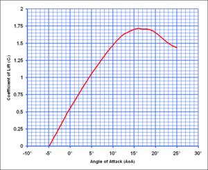
33 LIFT COEFFICIENT
34 THRUST Thrust is a force created by a power source which gives an airplane forward motion. It can either "pull" or "push" an airplane forward. Thrust is that force which overcomes drag. Thrust is generated by Propellers Jet engines
35 DRAG Drag is the aerodynamic force that opposes an aircraft's motion through the air Drag is generated by every part of the airplane Drag is generated by the difference in velocity between the solid object and the fluid For drag to be generated, the solid body must be in contact with the fluid. If there is no fluid, there is no drag Drag acts in a direction that is opposite to the motion of the aircraft
 Drag is comprises of Form drag (Pressure drag) Skin-friction drag Interference drag")
36 CLASSIFICATION OF DRAG Drag is generally divided into three categories: Parasitic drag Lift-induced drag Wave drag Parasitic (Parasite) Drag is comprises of Form drag (Pressure drag) Skin-friction drag Interference drag
37 TYPES OF DRAG Skin friction drag: Drag due to the skin friction between the molecules of air and the solid surface of the aircraft Form drag: Form drag is due to aerodynamic resistance to the motion of the object through the fluid. This drag depends on the shape of the aircraft Interference drag: Whenever two surfaces meet at a sharp angle on an airplane, the airflow has a tendency to form a vortex. Accelerating the air into this vortex causes drag on the plane Lift-induced drag: is a drag force which occurs whenever a lifting body generates lift Wave drag: Wave drag is associated with the formation of the shock waves Ram drag: Ram drag is associated with slowing down the free stream air as air is brought inside the aircraft

38 SKIN FRICTION DRAG Skin friction occurs because air has viscosity. The entire skin friction drag is created within the boundary layer Because air is viscous there is a shearing force occurring within the boundary layer
39 FORM DRAG Form drag depends primarily upon the size and shape of the object Form drag is due to the pressure difference between front and behind the object Flow separation increases form drag Ex: When we walk through water we will feel as though we are being held back. This is due to the combination of the build up of pressure in front of us, and the decrease in pressure behind us. This can be seen visually by the rising wave in front of us and the depression in the water behind us

40 FORM DRAG Form drag depends primarily upon the size and shape of the object Form drag is due to the pressure difference between front and behind the object

41 INTERFERENCE DRAG Interference drag is the effect of an aerodynamic component on another: wing-body, wing-nacelle, vertical-horizontal tail, junctions

42 INDUCED DRAG Induced drag occurs because the flow near the wing tips is distorted spanwise as a result of the pressure difference from the top to the bottom of the wing Swirling vortices are formed at the wing tips, which produce a down wash of air behind the wing which is very strong near the wing tips and decreases toward the wing root The local angle of attack of the wing is increased by the induced flow of the down wash, giving an additional, downstream-facing, component to the aerodynamic force acting over the entire wing


43 LIFT INDUCED DRAG F L D Induced drag 2 2W Di = πρev 2 b 2

44 REDUCTION OF INDUCED DRAG Winglets offer the best reduction in induced drag Winglets also produce additional thrust
45 WAVE DRAG Wave drag is caused by the formation of shock waves around the aircraft Shock waves radiate away a considerable amount of energy, energy that is experienced by the aircraft as drag Although shock waves are typically associated with supersonic flow, they can form at much lower speeds at areas on the aircraft where, according Bernoulli s principle, local airflow accelerates to supersonic speeds over curved areas The effect is typically seen at speeds of about Mach 0.8, but it is possible to notice the problem at any speed over that of the critical Mach of that aircraft's wing The magnitude of the rise in drag is impressive, typically peaking at about four times the normal subsonic drag
46 RAM DRAG Ram drag is associated with slowing down the free stream air as air is brought inside the aircraft V0 FD r = w0 g w0 Intake air mass flow g Acceleration due to gravity v0 Flight velocity
47 TOTAL DRAG Total drag 1 2 DT = ρv SC d 2 C d = C di + C dp
48 DRAG COEFFICIENT Bodies Drag Coefficient Airfoil Section, minimum [1] Airfoil Section, at stall [1] Element Airfoil Element Airfoil 0.05 Subsonic Aircraft Wing, minimum [2] 0.05 Subsonic Aircraft Wing, at stall [2] 0.16 Subsonic Aircraft Wing, minimum [3] Subsonic Aircraft Wing, at stall [3] 0.09 Subsonic Transport Aircraft Supersonic Fighter, M= Airship
49 WEIGHT ESTIMATION
50 AIRCRAFT WEIGHT DISTRIBUTION Weight breakup of the vehicle is Structural weight (40%) Payload (20%) Fuel weight (40%)
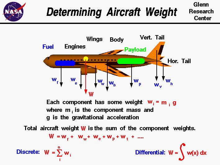
51 WEIGHT
52 WEIGHT Design takeoff gross weight is the total weight of the aircraft as it begins the mission for which it was designed Aircraft weight consists of Pay load Fuel Power plant Fixed equipment Structure Wo = W payload + W fuel + W power plant + W structure + W fixed equipment
53 PAYLOAD Payload consists of the weights of passenger, crew and luggage Wpayload = Wpassenger+Wcrew+Wbags+Wcargo
54 EMPTY WEIGHT Empty weight of the aircraft Wempty = W structure + W power plant + W fixed equipment Empty weight fraction for Jet aircraft 0.45 to 0.55 Turbo prop 0.55 to 0.61
55 STRUCTURAL WEIGHT Structural weight of the aircraft WStructure = Wwing+Wfuselage+Wtail+Wlanding gear
56 WING WEIGHT Wing weight = 8% of airplane weight W wing= (Wdg N Z ) S w A 0.5 ( c) t ( 1 + λ ) ( CosΛ ) S csw root Ref: P.Raymer Wing weight fraction ratio Wwg Wzf b = nult t r,max cos Λ c / 2 W wing= 4.22 S wg * cos Λc / 2 W zf b S N ult b 3 TOW * ZFW (1 + 2λ ) t Cos 2 ΛS wg (1 + λ ) c avg ( ) 0.3
57 FUSELAGE WEIGHT For L/d>5; the gross area of fuselage cabin is 2 S g = π dl 1 ( L/d) 2/ ( L / d ) Weight of fuselage is W f = 0.021S 1.2 g lt VD, E d Where W Weight (lbs) V Design dive speed (knots) f D,E
58 LANDING GEAR WEIGHT For main landing gear and nose landing gear Wmg = W 3/ 4 to Wng = W 3/ 4 to Wto W W 3/ 2 to For A/c with take off weight > lbs, landing gear weight is 3.5% to 4.5% 3/ 2 to
59 TAIL PLANE WEIGHT For main landing gear and nose landing gear Wmg = W 3/ 4 to Wng = W 3/ 4 to Wto W W 3/ 2 to For A/c with take off weight > lbs, landing gear weight is 3.5% to 4.5% 3/ 2 to
60 FUEL WEIGHT Fuel weight fraction (Wf/W0) can be estimated based on the mission profile of the aircraft Mission profile consists of Takeoff Climb Cruise Descend Loiter Landing Wx = W0 W0 Wf
61 TYPICAL MISSION PROFILE Takeoff (0-1) Climb (1-2) Cruise (2-3) Descend (3-4, 5-6) Loiter (4-5) Landing (6-7) 6 7
62 MISSION SEGMENT WEIGHT Mission segment weight fraction (Wi/Wi-1 ) is the weight at the end of the segment divided by weight at the beginning Mission segment weight fractions Takeoff Climb Landing 0.995
63 CRUISE MISSION WEIGHT Cruise segment weight fraction is calculated using Breguet range equation V L W i 1 R= ln C D Wi W i 1 RC = exp Wi V ( L / D)
64 LOITER FUEL WEIGHT Cruise fuel weight fraction is calculated from endurance equation 1 L W i 1 E= ln C D Wi W i 1 EC = exp Wi ( L / D) C specific fuel consumption
65 SPECIFIC FUEL CONSUMPTION Specific fuel consumption is the rate of fuel consumption divided by the resulting thrust SFC is measured as fuel mass flow per hour per unit thrust force Unit for SFC is lb of fuel/hr/lb of thrust (FPS system) mg/ns (Metric system) SFC for propeller engines are measured as Cbhp pounds of fuel per hour to produce one hp at the propeller shaft C = C bhp V 550η p
66 SPECIFIC FUEL CONSUMPTION Typical Jet SFC lb of fuel/hr/lb of thrust (mg/ns) Type Cruise Loiter Pure Turbojet 0.9 (25.5) 0.8 (22.7) Low-bypass turbofan 0.8 (22.7) 0.7 (19.8) High-bypass turbofan 0.5 (14.1) 0.4 (11.3) Propeller SFC lb/hr/bhp (mg/w.s) Piston prop (fixed pitch) 0.4 (0.068) 0.5 (0.085) Piston prop (variable pitch) 0.4 (0.068) 0.5 (0.085) Turboprop 0.5 (0.085) 0.6 (0.101)
67 EXAMPLE Takeoff weight W1/W0 =0.97 Climb Cruise W2/W1 =0.985 W3 RC = exp W2 V ( L / D) W * = exp = W2 204 * 13.9 Loiter W4 EC = exp ( ) W3 L / D W * = exp = W3 16 Land W5/W4=0.995 W5/W0=0.995*0.917*0.855*0.985*0.97=0.745 Wf/W0=1.06*( )=0.270
68 AIRCRAFT COORDINATE SYSTEM

69 STABILITY AND CONTROL
")
70 AIRCRAFT MOTIONS (Y) (X) (Z)
71 AIRCRAFT MOTIONS
72 ROLLING
73 ROLLING
74 ROLLING
75 PITCHING
76 PITCHING
77 YAWING
78 YAWING
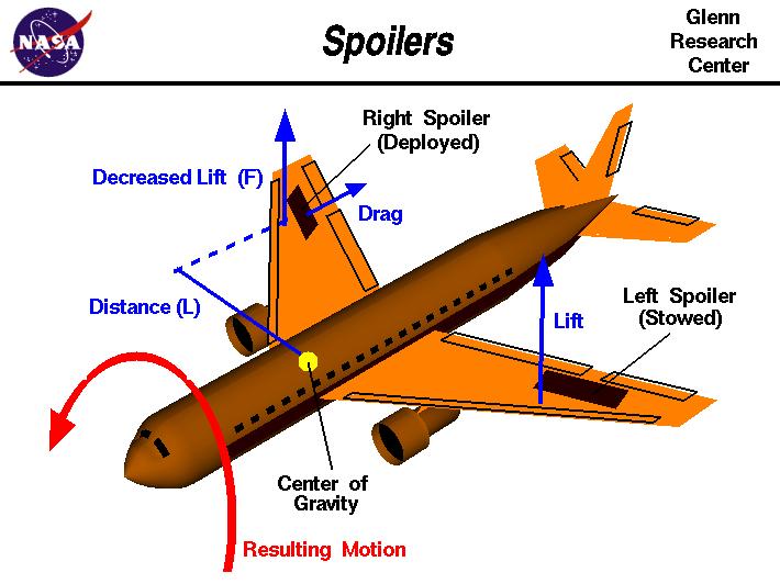
79 SPOILERS

80 FLAPS AND SLATS
81
DIRECCION DE PERSONAL AERONAUTICO DPTO. DE INSTRUCCION PREGUNTAS Y OPCIONES POR TEMA
 MT DIREION DE PERSONL ERONUTIO DPTO. DE INSTRUION PREGUNTS Y OPIONES POR TEM 1 TEM: 0292 FLT/DSP - (HP. 03) ERODYNMIS OD_PREG: PREG20084823 (8324) PREGUNT: When are inboard ailerons normally used? Low-speed
DIRECCION DE PERSONAL AERONAUTICO DPTO. DE INSTRUCCION PREGUNTAS Y OPCIONES POR TEMA
 MT DIREION DE PERSONL ERONUTIO DPTO. DE INSTRUION PREGUNTS Y OPIONES POR TEM 1 TEM: 0114 TP - (HP. 03) ERODYNMIS OD_PREG: PREG20078023 (8358) PREGUNT: What is the safest and most efficient takeoff and
BASIC AIRCRAFT STRUCTURES
 Slide 1 BASIC AIRCRAFT STRUCTURES The basic aircraft structure serves multiple purposes. Such as aircraft aerodynamics; which indicates how smooth the aircraft flies thru the air (The Skelton of the aircraft
Jet Propulsion. Lecture-17. Ujjwal K Saha, Ph. D. Department of Mechanical Engineering Indian Institute of Technology Guwahati
 Lecture-17 Prepared under QIP-CD Cell Project Jet Propulsion Ujjwal K Saha, Ph. D. Department of Mechanical Engineering Indian Institute of Technology Guwahati 1 Lift: is used to support the weight of
DEFINITIONS. Aerofoil
 Aerofoil DEFINITIONS An aerofoil is a device designed to produce more lift (or thrust) than drag when air flows over it. Angle of Attack This is the angle between the chord line of the aerofoil and the
Aero Club. Introduction to Flight
 Aero Club Presents Introduction to RC Modeling Module 1 Introduction to Flight Centre For Innovation IIT Madras Page2 Table of Contents Introduction:... 3 How planes fly How is lift generated?... 3 Forces
AIRCRAFT STRUCTURAL DESIGN & ANALYSIS K. RAMAJEYATHILAGAM
 AIRCRAFT STRUCTURAL DESIGN & ANALYSIS K. RAMAJEYATHILAGAM To invent an airplane is nothing To build one is something But to fly is everything Lilienthal DAY 1 WHAT IS AN AIRCRAFT? An aircraft is a vehicle,
WHAT IS GLIDER? A light engineless aircraft designed to glide after being towed aloft or launched from a catapult.
 GLIDER BASICS WHAT IS GLIDER? A light engineless aircraft designed to glide after being towed aloft or launched from a catapult. 2 PARTS OF GLIDER A glider can be divided into three main parts: a)fuselage
Theory of Flight Aircraft Design and Construction. References: FTGU pages 9-14, 27
 Theory of Flight 6.01 Aircraft Design and Construction References: FTGU pages 9-14, 27 Main Teaching Points Parts of an Airplane Aircraft Construction Landing Gear Standard Terminology Definition The airplane
A103 AERODYNAMIC PRINCIPLES
 A103 AERODYNAMIC PRINCIPLES References: FAA-H-8083-25A, Pilot s Handbook of Aeronautical Knowledge, Chapter 3 (pgs 4-10) and Chapter 4 (pgs 1-39) OBJECTIVE: Students will understand the fundamental aerodynamic
Aerodynamics Principles
 Aerodynamics Principles Stage 1 Ground Lesson 3 Chapter 3 / Pages 2-18 3:00 Hrs Harold E. Calderon AGI, CFI, CFII, and MEI Lesson Objectives Become familiar with the four forces of flight, aerodynamic
Aerodynamic Terms. Angle of attack is the angle between the relative wind and the wing chord line. [Figure 2-2] Leading edge. Upper camber.
![Aerodynamic Terms. Angle of attack is the angle between the relative wind and the wing chord line. [Figure 2-2] Leading edge. Upper camber.](/thumbs/82/86661300.jpg "Aerodynamic Terms. Angle of attack is the angle between the relative wind and the wing chord line. [Figure 2-2] Leading edge. Upper camber.") Chapters 2 and 3 of the Pilot s Handbook of Aeronautical Knowledge (FAA-H-8083-25) apply to powered parachutes and are a prerequisite to reading this book. This chapter will focus on the aerodynamic fundamentals
Chapters 2 and 3 of the Pilot s Handbook of Aeronautical Knowledge (FAA-H-8083-25) apply to powered parachutes and are a prerequisite to reading this book. This chapter will focus on the aerodynamic fundamentals
Detailed study 3.4 Topic Test Investigations: Flight
 Name: Billanook College Detailed study 3.4 Topic Test Investigations: Flight Ivanhoe Girls Grammar School Questions 1 and 2 relate to the information shown in the diagram in Figure 1. z Question 1 y Figure
The effect of back spin on a table tennis ball moving in a viscous fluid.
 How can planes fly? The phenomenon of lift can be produced in an ideal (non-viscous) fluid by the addition of a free vortex (circulation) around a cylinder in a rectilinear flow stream. This is known as
Learning Objectives 081 Principles of Flight
 Learning Objectives 081 Principles of Flight Conventions for questions in subject 081. 1. The following standard conventions are used for certain mathematical symbols: * multiplication. > = greater than
Aerodynamics. A study guide on aerodynamics for the Piper Archer
 Aerodynamics A study guide on aerodynamics for the Piper Archer Aerodynamics The purpose of this pilot briefing is to discuss the simple and complex aerodynamics of the Piper Archer. Please use the following
Stability and Flight Controls
 Stability and Flight Controls Three Axes of Flight Longitudinal (green) Nose to tail Lateral (blue) Wing tip to Wing tip Vertical (red) Top to bottom Arm Moment Force Controls The Flight Controls Pitch
Homework Exercise to prepare for Class #2.
 Homework Exercise to prepare for Class #2. Answer these on notebook paper then correct or improve your answers (using another color) by referring to the answer sheet. 1. Identify the major components depicted
SUBPART C - STRUCTURE
 SUBPART C - STRUCTURE GENERAL CS 23.301 Loads (a) Strength requirements are specified in terms of limit loads (the maximum loads to be expected in service) and ultimate loads (limit loads multiplied by
AE Dept., KFUPM. Dr. Abdullah M. Al-Garni. Fuel Economy. Emissions Maximum Speed Acceleration Directional Stability Stability.
 Aerodynamics: Introduction Aerodynamics deals with the motion of objects in air. These objects can be airplanes, missiles or road vehicles. The Table below summarizes the aspects of vehicle performance
Related Careers: Aircraft Instrument Repairer Aircraft Designer Aircraft Engineer Aircraft Electronics Specialist Aircraft Mechanic Pilot US Military
 Airplane Design and Flight Fascination with Flight Objective: 1. You will be able to define the basic terms related to airplane flight. 2. You will test fly your airplane and make adjustments to improve
It should be noted that the symmetrical airfoil at zero lift has no pitching moment about the aerodynamic center because the upper and
 NAVWEPS -81-8 and high power, the dynamic pressure in the shaded area can be much greater than the free stream and this causes considerably greater lift than at zero thrust. At high power conditions the
Flight Corridor. The speed-altitude band where flight sustained by aerodynamic forces is technically possible is called the flight corridor.
 Flight Corridor The speed-altitude band where flight sustained by aerodynamic forces is technically possible is called the flight corridor. The subsonic Boeing 747 and supersonic Concorde have flight corridors
OUTLINE SHEET BASIC THEORY. 2.1 DEFINE scalar, in a classroom, in accordance with Naval Aviation Fundamentals, NAVAVSCOLSCOM-SG-200
 Sheet 1 of 7 OUTLINE SHEET 2-1-1 BASIC THEORY A. INTRODUCTION This lesson is a basic introduction to the theory of aerodynamics. It provides a knowledge base in aerodynamic mathematics, air properties,
Chapter 3: Aircraft Construction
 Chapter 3: Aircraft Construction p. 1-3 1. Aircraft Design, Certification, and Airworthiness 1.1. Replace the letters A, B, C, and D by the appropriate name of aircraft component A: B: C: D: E: A = Empennage,
Welcome to Aerospace Engineering
 Welcome to Aerospace Engineering DESIGN-CENTERED INTRODUCTION TO AEROSPACE ENGINEERING Notes 4 Topics 1. Course Organization 2. Today's Dreams in Various Speed Ranges 3. Designing a Flight Vehicle: Route
LAPL(A)/PPL(A) question bank FCL.215, FCL.120 Rev PRINCIPLES OF FLIGHT 080
/PPL(A) question bank FCL.215, FCL.120 Rev PRINCIPLES OF FLIGHT 080") PRINCIPLES OF FLIGHT 080 1 Density: Is unaffected by temperature change. Increases with altitude increase. Reduces with temperature reduction. Reduces with altitude increase. 2 The air pressure that acts
PRINCIPLES OF FLIGHT 080 1 Density: Is unaffected by temperature change. Increases with altitude increase. Reduces with temperature reduction. Reduces with altitude increase. 2 The air pressure that acts
The Fly Higher Tutorial IV
 The Fly Higher Tutorial IV THE SCIENCE OF FLIGHT In order for an aircraft to fly we must have two things: 1) Thrust 2) Lift Aerodynamics The Basics Representation of the balance of forces These act against
ME 239: Rocket Propulsion. Forces Acting on a Vehicle in an Atmosphere (Follows Section 4.2) J. M. Meyers, PhD
 J. M. Meyers, PhD") ME 239: Rocket Propulsion Forces Acting on a Vehicle in an Atmosphere (Follows Section 4.2) J. M. Meyers, PhD 1 Commonly acting forces on a vehicle flying in a planetary atmosphere: Thrust Aerodynamic
ME 239: Rocket Propulsion Forces Acting on a Vehicle in an Atmosphere (Follows Section 4.2) J. M. Meyers, PhD 1 Commonly acting forces on a vehicle flying in a planetary atmosphere: Thrust Aerodynamic
Winnipeg Headingley Aero Modellers. Things About Airplanes.
 Winnipeg Headingley Aero Modellers Things About Airplanes. Table of Contents Introduction...2 The Airplane...2 How the Airplane is Controlled...3 How the Airplane Flies...6 Lift...6 Weight...8 Thrust...9
PRE-TEST Module 2 The Principles of Flight Units /60 points
 PRE-TEST Module 2 The Principles of Flight Units 1-2-3.../60 points 1 Answer the following questions. (20 p.) moving the plane (4) upward / forward. Opposed to that is 1. What are the names of the four
PRINCIPLES OF FLIGHT
 CHAPTER 3 PRINCIPLES OF FLIGHT INTRODUCTION Man has always wanted to fly. Legends from the very earliest times bear witness to this wish. Perhaps the most famous of these legends is the Greek myth about
XI.C. Power-Off Stalls
 References: FAA-H-8083-3; POH/AFM Objectives Key Elements Elements Schedule Equipment IP s Actions SP s Actions Completion Standards The student should develop knowledge of stalls regarding aerodynamics,
Basic Fluid Mechanics
 Basic Fluid Mechanics Chapter 7B: Forces on Submerged Bodies 7/26/2018 C7B: Forces on Submerged Bodies 1 Forces on Submerged Bodies Lift and Drag are forces exerted on an immersed body by the surrounding
JAR-23 Normal, Utility, Aerobatic, and Commuter Category Aeroplanes \ Issued 11 March 1994 \ Section 1- Requirements \ Subpart C - Structure \ General
 JAR 23.301 Loads \ JAR 23.301 Loads (a) Strength requirements are specified in terms of limit loads (the maximum loads to be expected in service) and ultimate loads (limit loads multiplied by prescribed
Preliminary Design Review (PDR) Aerodynamics #2 AAE-451 Aircraft Design
 Aerodynamics #2 AAE-451 Aircraft Design") Preliminary Design Review (PDR) Aerodynamics #2 AAE-451 Aircraft Design Aircraft Geometry (highlight any significant revisions since Aerodynamics PDR #1) Airfoil section for wing, vertical and horizontal
Preliminary Design Review (PDR) Aerodynamics #2 AAE-451 Aircraft Design Aircraft Geometry (highlight any significant revisions since Aerodynamics PDR #1) Airfoil section for wing, vertical and horizontal
LAPL/PPL question bank FCL.215, FCL.120 Rev PRINCIPLES OF FLIGHT 080
 LAPL/PPL question bank FCL.215, FCL.120 Rev. 1.7 11.10.2018 PRINCIPLES OF FLIGHT 080 1 Density: Reduces with temperature reduction. Increases with altitude increase. Reduces with altitude increase. Is
Uncontrolled copy not subject to amendment. Principles of Flight
 Uncontrolled copy not subject to amendment Principles of Flight Principles of Flight Learning Outcome 1: Know the principles of lift, weight, thrust and drag and how a balance of forces affects an aeroplane
ROAD MAP... D-1: Aerodynamics of 3-D Wings D-2: Boundary Layer and Viscous Effects D-3: XFLR (Aerodynamics Analysis Tool)
") Unit D-1: Aerodynamics of 3-D Wings Page 1 of 5 AE301 Aerodynamics I UNIT D: Applied Aerodynamics ROAD MAP... D-1: Aerodynamics of 3-D Wings D-: Boundary Layer and Viscous Effects D-3: XFLR (Aerodynamics
Unit D-1: Aerodynamics of 3-D Wings Page 1 of 5 AE301 Aerodynamics I UNIT D: Applied Aerodynamics ROAD MAP... D-1: Aerodynamics of 3-D Wings D-: Boundary Layer and Viscous Effects D-3: XFLR (Aerodynamics
XI.B. Power-On Stalls
 XI.B. Power-On Stalls References: AC 61-67; FAA-H-8083-3; POH/AFM Objectives Key Elements Elements Schedule Equipment IP s Actions SP s Actions Completion Standards The student should develop knowledge
Exploration Series. AIRPLANE Interactive Physics Simulation Page 01
 AIRPLANE ------- Interactive Physics Simulation ------- Page 01 What makes an airplane "stall"? An airplane changes its state of motion thanks to an imbalance in the four main forces acting on it: lift,
UNCORRECTED PAGE PROOFS
 CHAPTER 18 How do heavy things fly? Contents Flight the beginning Forces acting on an aircraft Moving through fluids The Equation of Continuity Fluid speed and pressure Aerofoil characteristics Newton
II.E. Airplane Flight Controls
 References: FAA-H-8083-3; FAA-8083-3-25 Objectives Key Elements Elements Schedule Equipment IP s Actions SP s Actions Completion Standards The student should develop knowledge of the elements related to
JAA Administrative & Guidance Material Section Five: Licensing, Part Two: Procedures
 INTRODUCTION Conventions for questions in subject 081. 1. The following standard conventions are used for certain mathematical symbols: * multiplication. >= greater than or equal to.
Reduction of Skin Friction Drag in Wings by Employing Riblets
 Reduction of Skin Friction Drag in Wings by Employing Riblets Kousik Kumaar. R 1 Assistant Professor Department of Aeronautical Engineering Nehru Institute of Engineering and Technology Coimbatore, India
Aerodynamics: The Wing Is the Thing
 Page B1 Chapter Two Chapter Two Aerodynamics: The Wing Is the Thing The Wing Is the Thing May the Four Forces Be With You 1. [B1/3/2] The four forces acting on an airplane in flight are A. lift, weight,
CHAPTER 9 PROPELLERS
 CHAPTER 9 CHAPTER 9 PROPELLERS CONTENTS PAGE How Lift is Generated 02 Helix Angle 04 Blade Angle of Attack and Helix Angle Changes 06 Variable Blade Angle Mechanism 08 Blade Angles 10 Blade Twist 12 PROPELLERS
CHAPTER 1 PRINCIPLES OF HELICOPTER FLIGHT FM 1-514
 CHAPTER 1 PRINCIPLES OF HELICOPTER FLIGHT Basic flight theory and aerodynamics are considered in full detail when an aircraft is designed. The rotor repairer must understand these principles in order to
AERODYNAMIC CHARACTERISTICS OF NACA 0012 AIRFOIL SECTION AT DIFFERENT ANGLES OF ATTACK
 AERODYNAMIC CHARACTERISTICS OF NACA 0012 AIRFOIL SECTION AT DIFFERENT ANGLES OF ATTACK SUPREETH NARASIMHAMURTHY GRADUATE STUDENT 1327291 Table of Contents 1) Introduction...1 2) Methodology.3 3) Results...5
Parasite Drag. by David F. Rogers Copyright c 2005 David F. Rogers. All rights reserved.
 Parasite Drag by David F. Rogers http://www.nar-associates.com Copyright c 2005 David F. Rogers. All rights reserved. How many of you still have a Grimes rotating beacon on both the top and bottom of the
ATPL Principles of Flight - deel 2
 ATPL Principles of Flight - deel 2 1. If flaps are deployed at constant IAS in straight and level flight, the magnitude of tip vortices will eventually: (flap span less then wing span) A decrease B remain
C-130 Reduction in Directional Stability at Low Dynamic Pressure and High Power Settings
 C-130 Reduction in Directional Stability at Low Dynamic Pressure and High Power Settings The C-130 experiences a marked reduction of directional stability at low dynamic pressures, high power settings,
Principles of glider flight
 Principles of glider flight [ Lecture 1: Lift, drag & glide performance ] Richard Lancaster Email: Richard@RJPLancaster.net Twitter: @RJPLancaster ASK-21 illustrations Copyright 1983 Alexander Schleicher
Lift for a Finite Wing. all real wings are finite in span (airfoils are considered as infinite in the span)
") Lift for a Finite Wing all real wings are finite in span (airfoils are considered as infinite in the span) The lift coefficient differs from that of an airfoil because there are strong vortices produced
Lift for a Finite Wing all real wings are finite in span (airfoils are considered as infinite in the span) The lift coefficient differs from that of an airfoil because there are strong vortices produced
LESSONS 1, 2, and 3 PRACTICE EXERCISES
 LESSONS 1, 2, and 3 PRACTICE EXERCISES The following items will test your grasp of the material covered in these lessons. There is only one correct answer for each item. When you complete the exercise,
Chapter 5 Wing design - selection of wing parameters - 3 Lecture 21 Topics
 Chapter 5 Wing design - selection of wing parameters - 3 Lecture 21 Topics 5.3.2 Choice of sweep ( ) 5.3.3 Choice of taper ratio ( λ ) 5.3.4 Choice of twist ( ε ) 5.3.5 Wing incidence(i w ) 5.3.6 Choice
HIGH ALTITUDE AERODYNAMICS
 HIGH ALTITUDE AERODYNAMICS CRITICAL ASPECTS OF MACH FLIGHT In recent years, a number of corporate jet airplanes have been involved in catastrophic loss of control during high-altitude/high-speed flight.
Airframes. Chapter 5: Wings & Tailplane
 Airframes Chapter 5: Wings & Tailplane 1 2 Learning Objectives The purpose of this chapter is to discuss in more detail, 2 of the 4 major components, the Wing (or mainplane) and the Tailplane. By the end
CFD ANALYSIS OF FLOW AROUND AEROFOIL FOR DIFFERENT ANGLE OF ATTACKS
 www.mechieprojects.com CFD ANALYSIS OF FLOW AROUND AEROFOIL FOR DIFFERENT ANGLE OF ATTACKS PRESENTATION OUTLINE AIM INTRODUCTION LITERATURE SURVEY CFD ANALYSIS OF AEROFOIL RESULTS CONCLUSIONS www.mechieprojects.com
Incompressible Flow over Airfoils
 Road map for Chap. 4 Incompressible Flow over Airfoils Aerodynamics 2015 fall - 1 - < 4.1 Introduction > Incompressible Flow over Airfoils Incompressible flow over airfoils Prandtl (20C 초 ) Airfoil (2D)
LEVEL FOUR AVIATION EVALUATION PRACTICE TEST
 Below you will find a practice test for the Level 4 Aviation Evaluation that covers PO431, PO432, PO436, and PO437. It is recommended that you focus on the material covered in the practice test as you
Aircraft Stability and Performance 2nd Year, Aerospace Engineering. Dr. M. Turner
 Aircraft Stability and Performance 2nd Year, Aerospace Engineering Dr. M. Turner Basic Info Timetable 15.00-16.00 Monday Physics LTA 16.00-17.00 Monday Physics LTA Exam 2 1 2 hour exam 6 questions 2 from
Theory of Flight Stalls. References: FTGU pages 18, 35-38
 Theory of Flight 6.07 Stalls References: FTGU pages 18, 35-38 Review 1. What are the two main types of drag? 2. Is it possible to eliminate induced drag? Why or why not? 3. What is one way to increase
Aerodynamic Analysis of a Symmetric Aerofoil
 214 IJEDR Volume 2, Issue 4 ISSN: 2321-9939 Aerodynamic Analysis of a Symmetric Aerofoil Narayan U Rathod Department of Mechanical Engineering, BMS college of Engineering, Bangalore, India Abstract - The
Aerodynamics of Flight
 Chapter 4 Aerodynamics of Flight Forces Acting on the Aircraft Thrust, drag, lift, and weight are forces that act upon all aircraft in flight. Understanding how these forces work and knowing how to control
Aerodynamic Analysis of Blended Winglet for Low Speed Aircraft
 , July 1-3, 2015, London, U.K. Aerodynamic Analysis of Blended Winglet for Low Speed Aircraft Pooja Pragati, Sudarsan Baskar Abstract This paper provides a practical design of a new concept of massive
The Metric Glider. By Steven A. Bachmeyer. Aerospace Technology Education Series
 The Metric Glider By Steven A. Bachmeyer Aerospace Technology Education Series 10002 Photographs and Illustrations The author wishes to acknowledge the following individuals and organizations for the photographs
AF101 to AF109. Subsonic Wind Tunnel Models AERODYNAMICS. A selection of optional models for use with TecQuipment s Subsonic Wind Tunnel (AF100)
") Page 1 of 4 A selection of optional models for use with TecQuipment s Subsonic Wind Tunnel (AF100) Dimpled Sphere Drag Model (from AF109) shown inside the TecQuipment AF100 Wind Tunnel. Cylinder, aerofoils,
Page 1 of 4 A selection of optional models for use with TecQuipment s Subsonic Wind Tunnel (AF100) Dimpled Sphere Drag Model (from AF109) shown inside the TecQuipment AF100 Wind Tunnel. Cylinder, aerofoils,
1 General. 1.1 Introduction
 1 General 1.1 Introduction The contents of this book will focus on the anatomy of the aeroplane and the various systems that enable it to operate both on the ground and in the air. Flight controls Landing
POWERED FLIGHT HOVERING FLIGHT
 Once a helicopter leaves the ground, it is acted upon by the four aerodynamic forces. In this chapter, we will examine these forces as they relate to flight maneuvers. POWERED FLIGHT In powered flight
CHAPTER 1 - PRINCIPLES OF FLIGHT
 CHAPTER 1 - PRINCIPLES OF FLIGHT Reilly Burke 2005 INTRODUCTION There are certain laws of nature or physics that apply to any object that is lifted from the Earth and moved through the air. To analyze
No Description Direction Source 1. Thrust
 AERODYNAMICS FORCES 1. WORKING TOGETHER Actually Lift Force is not the only force working on the aircraft, during aircraft moving through the air. There are several aerodynamics forces working together
Four forces on an airplane
 Four forces on an airplane By NASA.gov on 10.12.16 Word Count 824 Level MAX TOP: An airplane pictured on June 30, 2016. Courtesy of Pexels. BOTTOM: Four forces on an airplane. Courtesy of NASA. A force
The subsonic compressibility effect is added by replacing. with
 Swept Wings The main function of a swept wing is to reduce wave drag at transonic and supersonic speeds. Consider a straight wing and a swept wing in a flow with a free-stream velocity V. Assume that the
PEMP ACD2501. M.S. Ramaiah School of Advanced Studies, Bengaluru
 Aircraft Performance, Stability and Control Session delivered by: Mr. Ramjan Pathan 1 Session Objectives Aircraft Performance: Basicsof performance (t (steadystateand tt d accelerated) Performance characteristics
CASE STUDY FOR USE WITH SECTION B
 GCE A level 135/01-B PHYSICS ASSESSMENT UNIT PH5 A.M. THURSDAY, 0 June 013 CASE STUDY FOR USE WITH SECTION B Examination copy To be given out at the start of the examination. The pre-release copy must
Flight Control Systems Introduction
 Flight Control Systems Introduction Dr Slide 1 Flight Control System A Flight Control System (FCS) consists of the flight control surfaces, the respective cockpit controls, connecting linkage, and necessary
Principles of glider flight
 Principles of glider flight [ Lecture 2: Control and stability ] Richard Lancaster Email: Richard@RJPLancaster.net Twitter: @RJPLancaster ASK-21 illustrations Copyright 1983 Alexander Schleicher GmbH &
Compiled by Matt Zagoren
 The information provided in this document is to be used during simulated flight only and is not intended to be used in real life. Attention VA's - you may post this file on your site for download. Please
PILOT S HANDBOOK of Aeronautical Knowledge AC61-23C
 PILOT S HANDBOOK of Aeronautical Knowledge AC61-23C Revised 1997 Chapter 1 Excerpt Compliments of... www.alphatrainer.com Toll Free: (877) 542-1112 U.S. DEPARTMENT OF TRANSPORTATION FEDERAL AVIATION ADMINISTRATION
Wing-Body Combinations
 Wing-Body Combinations even a pencil at an angle of attack will generate lift, albeit small. Hence, lift is produced by the fuselage of an airplane as well as the wing. The mating of a wing with a fuselage
FORCES ACTING ON THE AIRPLANE
 CH 03.qxd 10/24/03 6:44 AM Page 3-1 FORCES ACTING ON THE AIRPLANE In some respects at least, how well a pilot performs in flight depends upon the ability to plan and coordinate the use of the power and
Takeoff Performance. A 1 C change in temperature from ISA will increase or decrease the takeoff ground roll by 10%.
 The precise pilot does not fly by rules of thumb, axioms, or formulas. But there are times when knowledge of an approximate way to calculate things or knowledge of a simple rule can pay big dividends.
BRONZE LECTURES. Slides on bayriver.co.uk/gliding
 BRONZE LECTURES 2014 Slides on bayriver.co.uk/gliding 1 STUDY Lectures only meant to be a stimulus and provide an opportunity for questions EXAM paper is multi-choice with x sections. 2 READING BOOKS?
TWO MARKS QUESTIONS AND ANSWERS
 TWO MARKS QUESTIONS AND ANSWERS 1) Define Range of an aircraft. Range of an aircraft is defined as the total distance travelled by an aircraft on one load of fuel. It is denoted by R. Range R= V L 2) Define
Investigation on 3-D Wing of commercial Aeroplane with Aerofoil NACA 2415 Using CFD Fluent
 Investigation on 3-D of commercial Aeroplane with Aerofoil NACA 2415 Using CFD Fluent Rohit Jain 1, Mr. Sandeep Jain 2, Mr. Lokesh Bajpai 3 1PG Student, 2 Associate Professor, 3 Professor & Head 1 2 3
bjectives The Realm of Flight Chapter The Composition and Properties of Air
 Chapter 7 - Basic Aeronautics and Aerodynamics Chapter 7 bjectives Explain the difference between aeronautics and aerodynamics. Understand the properties of air that are important to flight. Understand
PRIMARY FLIGHT CONTROLS. AILERONS Ailerons control roll about the longitudinal axis. The ailerons are attached to the outboard trailing edge of
 Aircraft flight control systems are classified as primary and secondary. The primary control systems consist of those that are required to safely control an airplane during flight. These include the ailerons,
The canard. Why such a configuration? Credit : Jean-François Edange
 The canard Why such a configuration? Credit : Jean-François Edange N obody doubtless knows that a great majority of light or heavy planes share a common design. Schematically, we find a fuselage, wings
LEVEL 4 COMBINED AVIATION REVIEW
 LEVEL 4 COMBINED AVIATION REVIEW LEVEL 4 COMBINED AVIATION REVIEW PO 431 EXPLAIN PRINCIPLES OF FLIGHT M431.01 EXPLAIN FEATURES OF WING DESIGN M431.02 DESCRIBE FLIGHT INSTRUMENTS PO 432 DESCRIBE AERO ENGINE
Created by Glenn Gibson Air and Aerodynamics Flight Note Pack
 Air and Aerodynamics Flight Note Pack Essential Questions of Aerodynamics The students should be able to answer the following questions: 1. Why does air exert pressure on objects in our atmosphere? 2.
Subsonic wind tunnel models
 aerodynamics AF1300a to AF1300l A selection of optional models for use with TecQuipment s Subsonic Wind Tunnel (AF1300) Dimpled Sphere Drag Model (from AF1300j) shown inside the TecQuipment AF1300 Wind
Induced Drag Reduction for Modern Aircraft without Increasing the Span of the Wing by Using Winglet
 International Journal of Mechanical & Mechatronics Engineering IJMME-IJENS Vol:10 No:03 49 Induced Drag Reduction for Modern Aircraft without Increasing the Span of the Wing by Using Winglet Mohammad Ilias
BUILD AND TEST A WIND TUNNEL
 LAUNCHING INTO AVIATION 9 2018 Aircraft Owners and Pilots Association. All Rights Reserved. UNIT 2 SECTION D LESSON 2 PRESENTATION BUILD AND TEST A WIND TUNNEL LEARNING OBJECTIVES By the end of this lesson,
Build This World Record Fuselage Model
 Build This World Record Fuselage Model Here You Have Complete Instructions and Plans to Build a Plane of Sure-fire Performance that Established a World Record at the 1932 National Airplane Model Competition
Fighter aircraft design. Aerospace Design Project G. Dimitriadis
 Fighter aircraft design Aerospace Design Project 2017-2018 G. Dimitriadis General configuration The elements of the general configuration are the following: Wing Wing placement Airfoil Number of engines
XI.D. Crossed-Control Stalls
 References: FAA-H-8083-3; POH/AFM Objectives Key Elements Elements Schedule Equipment IP s Actions SP s Actions Completion Standards The student should understand the dynamics of a crossed-control stall
Lesson: Airspeed Control
 11/20/2018 Airspeed Control Page 1 Lesson: Airspeed Control Objectives: o Knowledge o An understanding of the aerodynamics related to airspeed control o Skill o The ability to establish and maintain a
The Academy of Model Aeronautics ALPHA: Potential Energy Background Information for the Teacher
 The Academy of Model Aeronautics ALPHA: Potential Energy Background Information for the Teacher When the rubber motor of a model plane is wound it becomes a form of stored potential energy. As the rubber
External Tank- Drag Reduction Methods and Flow Analysis
 External Tank- Drag Reduction Methods and Flow Analysis Shaik Mohammed Anis M.Tech Student, MLR Institute of Technology, Hyderabad, India. G. Parthasarathy Associate Professor, MLR Institute of Technology,