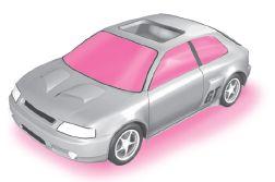
Chapter 11 EXTERNAL FLOW: DRAG AND LIFT
|
|
|
- Phoebe James
- 6 years ago
- Views:
Transcription
1 Fluid Mechanics: Fundamentals and Applications, 2nd Edition Yunus A. Cengel, John M. Cimbala McGraw-Hill, 2010 Lecture slides by Mehmet Kanoglu Copyright The McGraw-Hill Companies, Inc. Permission required for reproduction or display. Chapter 11 EXTERNAL FLOW: DRAG AND LIFT Lecturer: Prof. Dong Jin Cha, PhD Department of Building and Plant Engineering Hanbat National University


2 The wake of a Boeing 767 disrupts the top of a cumulus cloud and clearly shows the counter-rotating trailing vortices. 2
3 Objectives Have an intuitive understanding of the various physical phenomena associated with external flow such as drag, friction and pressure drag, drag reduction, and lift Calculate the drag force associated with flow over common geometries Understand the effects of flow regime on the drag coefficients associated with flow over cylinders and spheres Understand the fundamentals of flow over airfoils, and calculate the drag and lift forces acting on airfoils 3
4 11 1 INTRODUCTION Fluid flow over solid bodies frequently occurs in practice, and it is responsible for numerous physical phenomena such as the drag force acting on automobiles, power lines, trees, and underwater pipelines; the lift developed by airplane wings; upward draft of rain, snow, hail, and dust particles in high winds; the transportation of red blood cells by blood flow; the entrainment and disbursement of liquid droplets by sprays; the vibration and noise generated by bodies moving in a fluid; and the power generated by wind turbines. A fluid moving over a stationary body (such as the wind blowing over a building), and a body moving through a quiescent fluid (such as a car moving through air) are referred to as flow over bodies or external flow. 4

5 Flow over bodies is commonly encountered in practice. 5
6 6
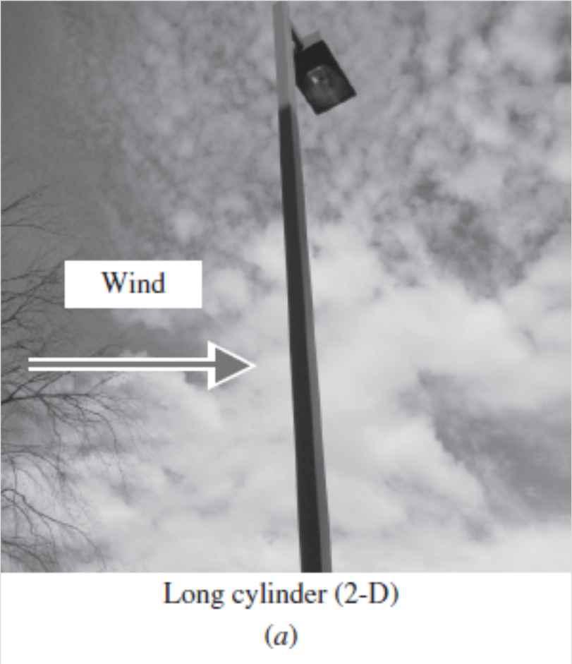
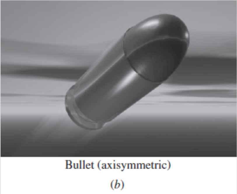
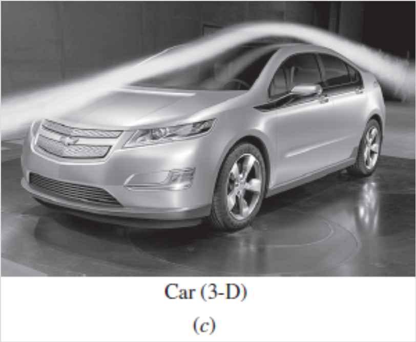
7 The flow fields and geometries for most external flow problems are too complicated and we have to rely on correlations based on experimental data. Free-stream velocity: The velocity of the fluid approaching a body (V or u or U ) Two-dimensional flow: When the body is very long and of constant cross section and the flow is normal to the body. Axisymmetric flow: When the body possesses rotational symmetry about an axis in the flow direction. The flow in this case is also two-dimensional. Three-dimensional flow: Flow over a body that cannot be modeled as twodimensional or axisymmetric such as flow over a car. Incompressible flows: (e.g., flows over automobiles, submarines, and buildings) Compressible flows: (e.g., flows over high-speed aircraft, rockets, and missiles). Compressibility effects are negligible at low velocities (flows with Ma < 0.3). Streamlined body: If a conscious effort is made to align its shape with the anticipated streamlines in the flow. Streamlined bodies such as race cars and airplanes appear to be contoured and sleek. Bluff or blunt body: If a body (such as a building) tends to block the flow. Usually it is much easier to force a streamlined body through a fluid. 7
8 Two-dimensional, axisymmetric, and threedimensional flows. 8


9 It is much easier to force a streamlined body than a blunt body through a fluid. 9

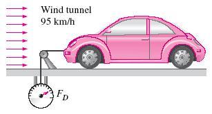
10 11 2 DRAG AND LIFT A body meets some resistance when it is forced to move through a fluid, especially a liquid. A fluid may exert forces and moments on a body in and about various directions. Drag: The force a flowing fluid exerts on a body in the flow direction. The drag force can be measured directly by simply attaching the body subjected to fluid flow to a calibrated spring and measuring the displacement in the flow direction. Drag is usually an undesirable effect, like friction, and we do our best to minimize it. But in some cases drag produces a very beneficial effect and we try to maximize it (e.g., automobile brakes). High winds knock down trees, power lines, and even people as a result of the drag force. 10
11 Lift: The components of the pressure and wall shear forces in the direction normal to the flow tend to move the body in that direction, and their sum is called lift. The fluid forces may generate moments and cause the body to rotate. Rolling moment: The moment about the flow direction. Yawing moment: The moment about the lift direction. Pitching moment: The moment about the side force direction. The pressure and viscous forces acting on a two-dimensional body and the resultant lift and drag forces. 11

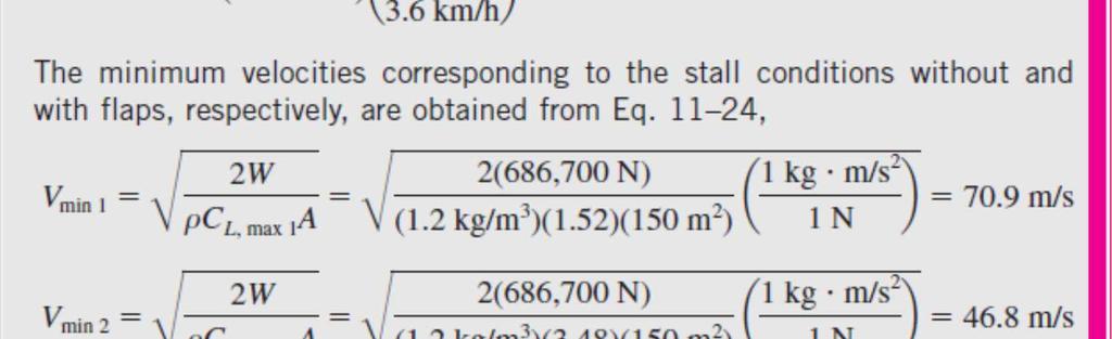
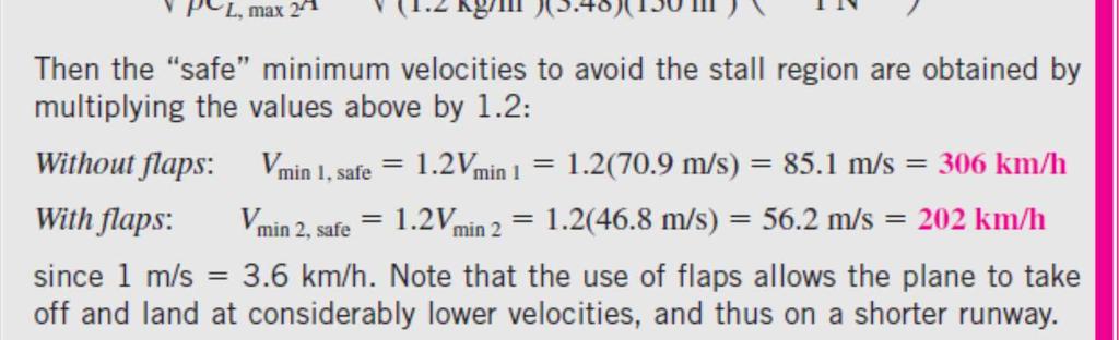
 Drag force acting on a flat plate normal to the flow depends on the pressure only and is independent of the wall")
12 Airplane wings are shaped and positioned to generate sufficient lift during flight while keeping drag at a minimum. Pressures above and below atmospheric pressure are indicated by plus and minus signs, respectively. (a) Drag force acting on a flat plate parallel to the flow depends on wall shear only. (b) Drag force acting on a flat plate normal to the flow depends on the pressure only and is independent of the wall shear, which acts normal to the free-stream flow. 12

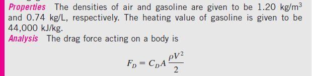
13 The drag and lift forces depend on the density of the fluid, the upstream velocity, and the size, shape, and orientation of the body. It is more convenient to work with appropriate dimensionless numbers that represent the drag and lift characteristics of the body. These numbers are the drag coefficient C D, and the lift coefficient C L. A frontal area dynamic pressure In lift and drag calculations of some thin bodies, such as airfoils, A is taken to be the planform area, which is the area seen by a person looking at the body from above in a direction normal to the body. During a free fall, a body reaches its terminal velocity when the drag force equals the weight of the body minus the buoyant force. 13
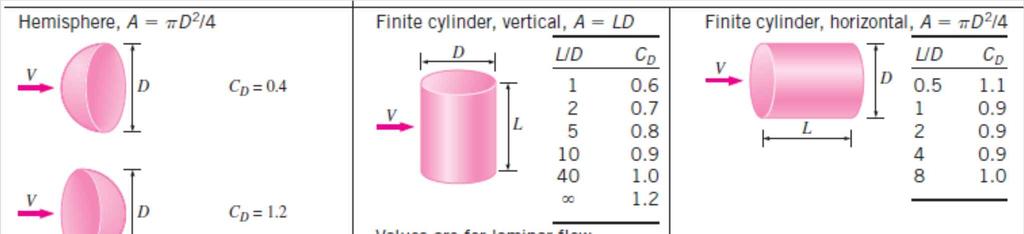
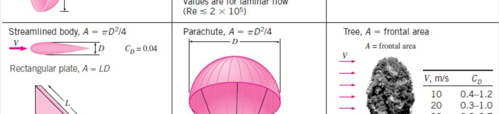
14 14
15 11 3 FRICTION AND PRESSURE DRAG The drag force is the net force exerted by a fluid on a body in the direction of flow due to the combined effects of wall shear and pressure forces. The part of drag that is due directly to wall shear stress is called the skin friction drag (or just friction drag) since it is caused by frictional effects, and the part that is due directly to pressure is called the pressure drag (also called the form drag because of its strong dependence on the form or shape of the body). The friction drag is the component of the wall shear force in the direction of flow, and thus it depends on the orientation of the body as well as the magnitude of the wall shear stress. For parallel flow over a flat surface, the drag coefficient is equal to the friction drag coefficient. Friction drag is a strong function of viscosity, and increases with increasing viscosity. 15


16 Drag is due entirely to friction drag for a flat plate parallel to the flow; it is due entirely to pressure drag for a flat plate normal to the flow; and it is due to both (but mostly pressure drag) for a cylinder normal to the flow. The total drag coefficient C D is lowest for a parallel flat plate, highest for a vertical flat plate, and in between (but close to that of a vertical flat plate) for a cylinder. 16
17 Reducing Drag by Streamlining Streamlining decreases pressure drag by delaying boundary layer separation and thus reducing the pressure difference between the front and back of the body but increases the friction drag by increasing the surface area. The end result depends on which effect dominates. The variation of friction, pressure, and total drag coefficients of a streamlined strut with thickness-to-chord length ratio for Re = Note that C D for airfoils and other thin bodies is based on planform area rather than frontal area. 17
18 The variation of the drag coefficient of a long elliptical cylinder with aspect ratio. Here C D is based on the frontal area bd where b is the width of the body. The drag coefficient decreases drastically as the ellipse becomes slimmer. The reduction in the drag coefficient at high aspect ratios is primarily due to the boundary layer staying attached to the surface longer and the resulting pressure recovery. Streamlining has the added benefit of reducing vibration and noise. Streamlining should be considered only for blunt bodies that are subjected to highvelocity fluid flow (and thus high Reynolds numbers) for which flow separation is a real possibility. Streamlining is not necessary for bodies that typically involve low Reynolds number flows. 18


19 Flow Separation Flow separation: At sufficiently high velocities, the fluid stream detaches itself from the surface of the body. The location of the separation point depends on several factors such as the Reynolds number, the surface roughness, and the level of fluctuations in the free stream, and it is usually difficult to predict exactly where separation will occur. Flow separation over a backwardfacing step along a wall. Flow separation in a waterfall. 19

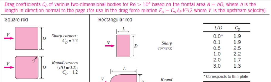
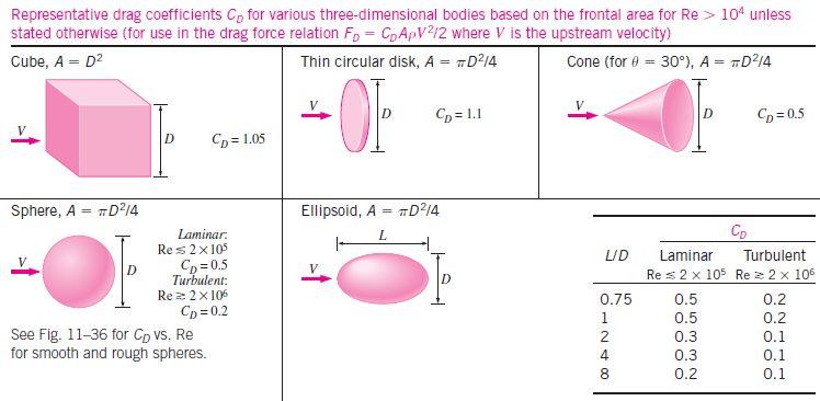
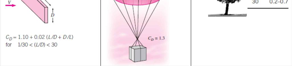
20 Separated region: When a fluid separates from a body, it forms a separated region between the body and the fluid stream. This is a low-pressure region behind the body where recirculating and backflows occur. The larger the separated region, the larger the pressure drag. The effects of flow separation are felt far downstream in the form of reduced velocity (relative to the upstream velocity). Wake: The region of flow trailing the body where the effects of the body on velocity are felt. Viscous and rotational effects are the most significant in the boundary layer, the separated region, and the wake. Flow separation and the wake region during flow over a tennis ball. 20


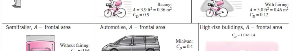
21 At large angles of attack (usually larger than 15 ), flow may separate completely from the top surface of an airfoil, reducing lift drastically and causing the airfoil to stall. An important consequence of flow separation is the formation and shedding of circulating fluid structures, called vortices, in the wake region. The periodic generation of these vortices downstream is referred to as vortex shedding. The vibrations generated by vortices near the body may cause the body to resonate to dangerous levels. 21
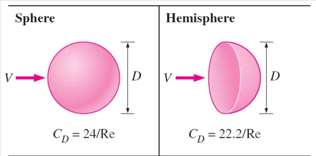
22 11 4 DRAG COEFFICIENTS OF COMMON GEOMETRIES The drag behavior of various natural and human-made bodies is characterized by their drag coefficients measured under typical operating conditions. Usually the total (friction+pressure) drag coefficient is reported. The drag coefficient exhibits different behavior in the low (creeping), moderate (laminar), and high (turbulent) regions of the Reynolds number. The inertia effects are negligible in low Reynolds number flows (Re < 1), called creeping flows, and the fluid wraps around the body smoothly. Creeping flow, sphere The drag coefficient for many (but not all) geometries remains essentially constant at Reynolds numbers above about Stokes law Stokes law is often applicable to dust particles in the air and suspended solid particles in water. 22
23 23
24 24
25 25
26 26
27 27
28 Observations from the drag coefficient tables The orientation of the body relative to the direction of flow has a major influence on the drag coefficient. For blunt bodies with sharp corners, such as flow over a rectangular block or a flat plate normal to flow, separation occurs at the edges of the front and back surfaces, with no significant change in the character of flow. Therefore, the drag coefficient of such bodies is nearly independent of the Reynolds number. The drag coefficient of a long rectangular rod can be reduced almost by half from 2.2 to 1.2 by rounding the corners. The drag coefficient of a body may change drastically by changing the body s orientation (and thus shape) relative to the direction of flow. 28
, are highly streamlined to minimize drag (the drag coefficient of dolphins based on the wetted skin area")
29 Biological Systems and Drag The concept of drag also has important consequences for biological systems. The bodies of fish, especially the ones that swim fast for long distances (such as dolphins), are highly streamlined to minimize drag (the drag coefficient of dolphins based on the wetted skin area is about , comparable to the value for a flat plate in turbulent flow). Airplanes, which look somewhat like big birds, retract their wheels after takeoff in order to reduce drag and thus fuel consumption. The flexible structure of plants enables them to reduce drag at high winds by changing their shapes. Large flat leaves, for example, curl into a low-drag conical shape at high wind speeds, while tree branches cluster to reduce drag. Flexible trunks bend under the influence of the wind to reduce drag, and the bending moment is lowered by reducing frontal area. Horse and bicycle riders lean forward as much as they can to reduce drag. Birds teach us a lesson on drag reduction by extending their beak forward and folding their feet backward during flight. 29


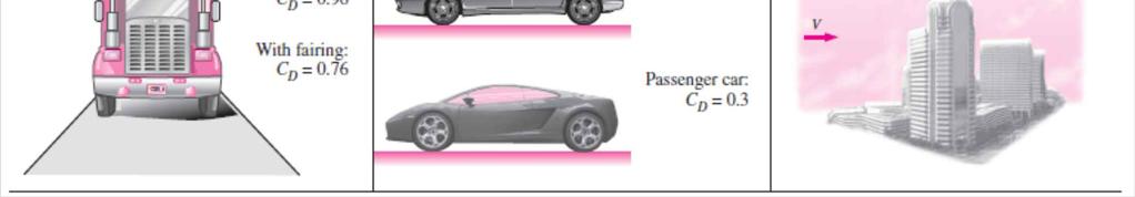
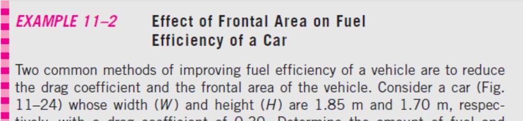
30 Drag Coefficients of Vehicles The drag coefficients of vehicles range from about 1.0 for large semitrailers to 0.4 for minivans, 0.3 for passenger cars, and 0.2 for race cars. The theoretical lower limit is about 0.1. In general, the more blunt the vehicle, the higher the drag coefficient. Installing a fairing reduces the drag coefficient of tractor-trailer rigs by about 20 percent by making the frontal surface more streamlined. As a rule of thumb, the percentage of fuel savings due to reduced drag is about half the percentage of drag reduction at highway speeds. This sleek-looking Toyota Prius has a drag coefficient of 0.26 one of the lowest for a passenger car. Streamlines around an aerodynamically designed modern car closely resemble the streamlines around the car in the ideal potential flow (assumes negligible friction), except near the rear end, resulting in a low drag coefficient. 30

31 The aerodynamic drag is negligible at low speeds, but becomes significant at speeds above about 50 km/h. At highway speeds, a driver can often save fuel in hot weather by running the air conditioner instead of driving with the windows rolled down. The turbulence and additional drag generated by open windows consume more fuel than does the air conditioner. The drag coefficients of bodies following other moving bodies closely can be reduced considerably due to drafting (i.e., falling into the low pressure region created by the body in front). Superposition The shapes of many bodies encountered in practice are not simple. But such bodies can be treated conveniently in drag force calculations by considering them to be composed of two or more simple bodies. A satellite dish mounted on a roof with a cylindrical bar, for example, can be considered to be a combination of a hemispherical body and a cylinder. Then the drag coefficient of the body can be determined approximately by using superposition. 31
32 32
33 33
34 34

35 11 5 PARALLEL FLOW OVER FLAT PLATES Velocity boundary layer: The region of the flow above the plate bounded by d in which the effects of the viscous shearing forces caused by fluid viscosity are felt. The boundary layer thickness d is typically defined as the distance y from the surface at which u = 0.99V. The hypothetical curve of u = 0.99V divides the flow into two regions: Boundary layer region: The viscous effects and the velocity changes are significant. Irotational flow region: The frictional effects are negligible and the velocity remains essentially constant. The development of the boundary layer for flow over a flat plate, and the different flow regimes. Not to scale. 35

36 The turbulent boundary layer can be considered to consist of four regions, characterized by the distance from the wall: viscous sublayer buffer layer overlap layer turbulent layer Friction coefficient on a flat plate Friction force on a flat plate The development of a boundary layer on a surface is due to the noslip condition and friction. For parallel flow over a flat plate, the pressure drag is zero, and thus the drag coefficient is equal to the friction coefficient and the drag force is equal to the friction force. 36
37 The transition from laminar to turbulent flow depends on the surface geometry, surface roughness, upstream velocity, surface temperature, and the type of fluid, among other things, and is best characterized by the Reynolds number. The Reynolds number at a distance x from the leading edge of a flat plate is expressed as V upstream velocity x characteristic length of the geometry (for a flat plate, it is the length of the plate in the flow direction) For flow over a smooth flat plate, transition from laminar to turbulent begins at about Re» , but does not become fully turbulent before the Reynolds number reaches much higher values, typically around In engineering analysis, a generally accepted value for the critical Reynolds number is The actual value of the engineering critical Reynolds number for a flat plate may vary somewhat from about 10 5 to depending on the surface roughness, the turbulence level, and the variation of pressure along the surface. 37

38 Friction Coefficient The friction coefficient for laminar flow over a flat plate can be determined theoretically by solving the conservation of mass and momentum equations numerically. For turbulent flow, it must be determined experimentally and expressed by empirical correlations. The variation of the local friction coefficient for flow over a flat plate. Note that the vertical scale of the boundary layer is greatly exaggerated in this sketch. 38
39 Average friction coefficient over the entire plate When the laminar flow region is not disregarded The average friction coefficient over a surface is determined by integrating the local friction coefficient over the entire surface. The values shown here are for a laminar flat plate boundary layer. 39

40 For laminar flow, the friction coefficient depends only on the Reynolds number, and the surface roughness has no effect. For turbulent flow, surface roughness causes the friction coefficient to increase severalfold, to the point that in the fully rough turbulent regime the friction coefficient is a function of surface roughness alone and is independent of the Reynolds number. e the surface roughness L the length of the plate in the flow direction. This relation can be used for turbulent flow on rough surfaces for Re > 10 6, especially when e/l > For turbulent flow, surface roughness may cause the friction coefficient to increase severalfold. 40
41 C f increases severalfold with roughness in turbulent flow. C f is independent of the Reynolds number in the fully rough region. This chart is the flatplate analog of the Moody chart for pipe flows. Friction coefficient for parallel flow over smooth and rough flat plates for both laminar and turbulent flows. 41
42 42
43 43


44 11 6 FLOW OVER CYLINDERS AND SPHERES Flow over cylinders and spheres is frequently encountered in practice. The tubes in a shell-and-tube heat exchanger involve both internal flow through the tubes and external flow over the tubes. Many sports such as soccer, tennis, and golf involve flow over spherical balls. At very low velocities, the fluid completely wraps around the cylinder. Flow in the wake region is characterized by periodic vortex formation and low pressures. Laminar boundary layer separation with a turbulent wake; flow over a circular cylinder at Re=

 and to pressure drag at high Reynolds numbers (Re>5000).")
45 For flow over cylinder or sphere, both the friction drag and the pressure drag can be significant. The high pressure in the vicinity of the stagnation point and the low pressure on the opposite side in the wake produce a net force on the body in the direction of flow. The drag force is primarily due to friction drag at low Reynolds numbers (Re<10) and to pressure drag at high Reynolds numbers (Re>5000). Both effects are significant at intermediate Reynolds numbers. Average drag coefficient for cross-flow over a smooth circular cylinder and a smooth sphere. 45
46 Observations from C D curves For Re<1, we have creeping flow, and the drag coefficient decreases with increasing Reynolds number. For a sphere, it is C D =24/Re. There is no flow separation in this regime. At about Re=10, separation starts occurring on the rear of the body with vortex shedding starting at about Re=90. The region of separation increases with increasing Reynolds number up to about Re=10 3. At this point, the drag is mostly (about 95 percent) due to pressure drag. The drag coefficient continues to decrease with increasing Reynolds number in this range of 10<Re<10 3. In the moderate range of 10 3 <Re<10 5, the drag coefficient remains relatively constant. This behavior is characteristic of bluff bodies. The flow in the boundary layer is laminar in this range, but the flow in the separated region past the cylinder or sphere is highly turbulent with a wide turbulent wake. There is a sudden drop in the drag coefficient somewhere in the range of 10 5 <Re<10 6 (usually, at about ). This large reduction in C D is due to the flow in the boundary layer becoming turbulent, which moves the separation point further on the rear of the body, reducing the size of the wake and thus the magnitude of the pressure drag. This is in contrast to streamlined bodies, which experience an increase in the drag coefficient (mostly due to friction drag) when the boundary layer becomes turbulent. There is a transitional regime for <Re<2 10 6, in which C D dips to a minimum value and then slowly rises to its final turbulent value. 46


47 Flow separation occurs at about q = 80 (measured from the front stagnation point of a cylinder) when the boundary layer is laminar and at about q = 140 when it is turbulent. The delay of separation in turbulent flow is caused by the rapid fluctuations of the fluid in the transverse direction, which enables the turbulent boundary layer to travel farther along the surface before separation occurs, resulting in a narrower wake and a smaller pressure drag. Flow visualization of flow over (a) a smooth sphere at Re = 15,000, and (b) a sphere at Re = 30,000 with a trip wire. The delay of boundary layer separation is clearly seen by comparing the two photographs. 47
48 Effect of Surface Roughness Surface roughness, in general, increases the drag coefficient in turbulent flow. This is especially the case for streamlined bodies. For blunt bodies such as a circular cylinder or sphere, however, an increase in the surface roughness may increase or decrease the drag coefficient depending on Reynolds number. The effect of surface roughness on the drag coefficient of a sphere. 48

.")
49 Surface roughness may increase or decrease the drag coefficient of a spherical object, depending on the value of the Reynolds number. Roughening the surface can be used to great advantage in reducing drag. Golf balls are intentionally roughened to induce turbulence at a lower Reynolds number to take advantage of the sharp drop in the drag coefficient at the onset of turbulence in the boundary layer (the typical velocity range of golf balls is 15 to 150 m/s, and the Reynolds number is less than ). The occurrence of turbulent flow at this Reynolds number reduces the drag coefficient of a golf ball by about half. For a given hit, this means a longer distance for the ball. For a table tennis ball, however, the speeds are slower and the ball is smaller it never reaches speeds in the turbulent range. Therefore, the surfaces of table tennis balls are made smooth. Drag force relation Frontal area for a cylinder and sphere 49
50 50
51 51

52 11 7 LIFT Lift: The component of the net force (due to viscous and pressure forces) that is perpendicular to the flow direction. Lift coefficient A planform area: the area that would be seen by a person looking at the body from above in a direction normal to the body Definition of various terms associated with an airfoil. For an aircraft, the wingspan is the total distance between the tips of the two wings, which includes the width of the fuselage between the wings. The average lift per unit planform area F L /A is called the wing loading, which is simply the ratio of the weight of the aircraft to the planform area of the wings (since lift equals the weight during flying at constant altitude). 52
53 Airfoils are designed to generate lift while keeping the drag at a minimum. Some devices such as the spoilers and inverted airfoils on racing cars are designed for avoiding lift or generating negative lift to improve traction and control. Lift in practice can be taken to be due entirely to the pressure distribution on the surfaces of the body, and thus the shape of the body has the primary influence on lift. Then the primary consideration in the design of airfoils is minimizing the average pressure at the upper surface while maximizing it at the lower surface. Pressure is low at locations where the flow velocity is high, and pressure is high at locations where the flow velocity is low. Lift at moderate angles of attack is practically independent of the surface roughness since roughness affects the wall shear, not the pressure. For airfoils, the contribution of viscous effects to lift is usually negligible since wall shear is parallel to the surfaces and thus nearly normal to the direction of lift. 53


54 Shortly after a sudden increase in angle of attack, a counterclockwise starting vortex is shed from the airfoil, while clockwise circulation appears around the airfoil, causing lift to be generated. Irrotational and actual flow past symmetrical and nonsymmetrical twodimensional airfoils. 54
55 It is desirable for airfoils to generate the most lift while producing the least drag. Therefore, a measure of performance for airfoils is the lift-to-drag ratio, which is equivalent to the ratio of the lift-to-drag coefficients C L /C D. The C L /C D ratio increases with the angle of attack until the airfoil stalls, and the value of the lift-to-drag ratio can be of the order of 100 for a twodimensional airfoil. The variation of the liftto-drag ratio with angle of attack for a twodimensional airfoil. 55

56 One way to change the lift and drag characteristics of an airfoil is to change the angle of attack. On an airplane, the entire plane is pitched up to increase lift, since the wings are fixed relative to the fuselage. Another approach is to change the shape of the airfoil by the use of movable leading edge and trailing edge flaps. The flaps are used to alter the shape of the wings during takeoff and landing to maximize lift at low speeds. Once at cruising altitude, the flaps are retracted, and the wing is returned to its normal shape with minimal drag coefficient and adequate lift coefficient to minimize fuel consumption while cruising at a constant altitude. Note that even a small lift coefficient can generate a large lift force during normal operation because of the large cruising velocities of aircraft and the proportionality of lift to the square of flow velocity. The lift and drag characteristics of an airfoil during takeoff and landing can be changed by changing the shape of the airfoil by the use of movable flaps. 56
57 Effect of flaps on the lift and drag coefficients of an airfoil. The maximum lift coefficient increases from about 1.5 for the airfoil with no flaps to 3.5 for the double-slotted flap case. The maximum drag coefficient increases from about 0.06 for the airfoil with no flaps to about 0.3 for the double-slotted flap case. The angle of attack of the flaps can be increased to maximize the lift coefficient. 57

58 The minimum flight velocity can be determined from the requirement that the total weight W of the aircraft be equal to lift and C L = C L, max : For a given weight, the landing or takeoff speed can be minimized by maximizing the product of the lift coefficient and the wing area, C L, max A. One way of doing that is to use flaps. Another way is to control the boundary layer, which can be accomplished simply by leaving flow sections (slots) between the flaps. Slots are used to prevent the separation of the boundary layer from the upper surface of the wings and the flaps. This is done by allowing air to move from the high-pressure region under the wing into the low-pressure region at the top surface. A flapped airfoil with a slot to prevent the separation of the boundary layer from the upper surface and to increase the lift coefficient. 58
59 The variation of the lift coefficient with the angle of attack for a symmetrical and a nonsymmetrical airfoil. C L increases almost linearly with the angle of attack a, reaches a maximum at about a=16, and then starts to decrease sharply. This decrease of lift with further increase in the angle of attack is called stall, and it is caused by flow separation and the formation of a wide wake region over the top surface of the airfoil. Stall is highly undesirable since it also increases drag. At zero angle of attack (a = 0 ), the lift coefficient is zero for symmetrical airfoils but nonzero for nonsymmetrical ones with greater curvature at the top surface. Therefore, planes with symmetrical wing sections must fly with their wings at higher angles of attack in order to produce the same lift. The lift coefficient can be increased severalfold by adjusting the angle of attack (from 0.25 at a =0 for the nonsymmetrical airfoil to 1.25 at a =10 ). 59
60 The drag coefficient increases with the angle of attack, often exponentially. Therefore, large angles of attack should be used sparingly for short periods of time for fuel efficiency. The variation of the drag coefficient of an airfoil with the angle of attack. 60
61 Finite-Span Wings and Induced Drag For airplane wings and other airfoils of finite span, the end effects at the tips become important because of the fluid leakage between the lower and upper surfaces. The pressure difference between the lower surface (highpressure region) and the upper surface (low-pressure region) drives the fluid at the tips upward while the fluid is swept toward the back because of the relative motion between the fluid and the wing. This results in a swirling motion that spirals along the flow, called the tip vortex, at the tips of both wings. Vortices are also formed along the airfoil between the tips of the wings. These distributed vortices collect toward the edges after being shed from the trailing edges of the wings and combine with the tip vortices to form two streaks of powerful trailing vortices along the tips of the wings 61
")


62 Trailing vortices visualized in various ways: (a) Smoke streaklines in a wind tunnel show vortex cores leaving the trailing edge of a rectangular wing; (b) Four contrails initially formed by condensation of water vapor in the low pressure region behind the jet engines eventually merge into the two counter-rotating trailing vortices that persist very far downstream; (c) A crop duster flies through smoky air which swirls around in one of the tip vortices from the aircraft's wing. 62
 Geese flying in their characteristic V-formation to save energy. (b) Military jets imitating nature.")
63 It has been determined that the birds in a typical flock can fly to their destination in V-formation with onethird less energy (by utilizing the updraft generated by the bird in front). Military jets also occasionally fly in V- formation for the same reason (a) Geese flying in their characteristic V-formation to save energy. (b) Military jets imitating nature. Tip vortices that interact with the free stream impose forces on the wing tips in all directions, including the flow direction. The component of the force in the flow direction adds to drag and is called induced drag. The total drag of a wing is then the sum of the induced drag (3-D effects) and the drag of the airfoil section (2-D effects). 63


64 Aspect ratio: The ratio of the square of the average span of an airfoil to the planform area. For an airfoil with a rectangular planform of chord c and span b, The aspect ratio is a measure of how narrow an airfoil is in the flow direction. The lift coefficient of wings, in general, increases while the drag coefficient decreases with increasing aspect ratio. Bodies with large aspect ratios fly more efficiently, but they are less maneuverable because of their larger moment of inertia (owing to the greater distance from the center). Induced drag is reduced by (a) wing tip feathers on bird wings and (b) endplates or other disruptions on airplane wings. 64


65 Lift Generated by Spinning Magnus effect: The phenomenon of producing lift by the rotation of a solid body. When the ball is not spinning, the lift is zero because of top bottom symmetry. But when the cylinder is rotated about its axis, the cylinder drags some fluid around because of the no-slip condition and the flow field reflects the superposition of the spinning and nonspinning flows. Generation of lift on a rotating circular cylinder for the case of idealized potential flow (the actual flow involves flow separation in the wake region). 65

66 Note that the lift coefficient strongly depends on the rate of rotation, especially at low angular velocities. The effect of the rate of rotation on the drag coefficient is small. Roughness also affects the drag and lift coefficients. In a certain range of Reynolds number, roughness produces the desirable effect of increasing the lift coefficient while decreasing the drag coefficient. Therefore, golf balls with the right amount of roughness travel higher and farther than smooth balls for the same hit. 66
67 67
68 68
69 69
70 70
71 71

72 The Wright Brothers are truly the most impressive engineering team of all time. Self-taught, they were well informed of the contemporary theory and practice in aeronautics. They both corresponded with other leaders in the field and published in technical journals. While they cannot be credited with developing the concepts of lift and drag, they used them to achieve the first powered, manned, heavierthan-air, controlled flight. They succeeded, while so many before them failed, because they evaluated and designed parts separately. Before the Wrights, experimenters were building and testing whole airplanes. The Wright Brothers take flight at Kitty Hawk. 72
73 Summary Introduction Drag and Lift Friction and Pressure Drag ü Reducing Drag by Streamlining ü Flow Separation Drag Coefficients of Common Geometries ü Biological Systems and Drag ü Drag Coefficients of Vehicles ü Superposition Parallel Flow Over Flat Plates ü Friction Coefficient Flow Over Cylinders and Spheres ü Effect of Surface Roughness Lift ü Finite-Span Wings and Induced Drag ü Lift Generated by Spinning 73
Flow Over Bodies: Drag and Lift
 Fluid Mechanics (0905241) Flow Over Bodies: Drag and Lift Dr.-Eng. Zayed dal-hamamre 1 Content Overview Drag and Lift Flow Past Objects Boundary Layers Laminar Boundary Layers Transitional and Turbulent
The effect of back spin on a table tennis ball moving in a viscous fluid.
 How can planes fly? The phenomenon of lift can be produced in an ideal (non-viscous) fluid by the addition of a free vortex (circulation) around a cylinder in a rectilinear flow stream. This is known as
AE Dept., KFUPM. Dr. Abdullah M. Al-Garni. Fuel Economy. Emissions Maximum Speed Acceleration Directional Stability Stability.
 Aerodynamics: Introduction Aerodynamics deals with the motion of objects in air. These objects can be airplanes, missiles or road vehicles. The Table below summarizes the aspects of vehicle performance
Basic Fluid Mechanics
 Basic Fluid Mechanics Chapter 7B: Forces on Submerged Bodies 7/26/2018 C7B: Forces on Submerged Bodies 1 Forces on Submerged Bodies Lift and Drag are forces exerted on an immersed body by the surrounding
THE BRIDGE COLLAPSED IN NOVEMBER 1940 AFTER 4 MONTHS OF ITS OPENING TO TRAFFIC!
 OUTLINE TACOMA NARROWS BRIDGE FLOW REGIME PAST A CYLINDER VORTEX SHEDDING MODES OF VORTEX SHEDDING PARALLEL & OBLIQUE FLOW PAST A SPHERE AND A CUBE SUMMARY TACOMA NARROWS BRIDGE, USA THE BRIDGE COLLAPSED
AERODYNAMICS I LECTURE 7 SELECTED TOPICS IN THE LOW-SPEED AERODYNAMICS
 LECTURE 7 SELECTED TOPICS IN THE LOW-SPEED AERODYNAMICS The sources of a graphical material used in this lecture are: [UA] D. McLean, Understanding Aerodynamics. Arguing from the Real Physics. Wiley, 2013.
Parasite Drag. by David F. Rogers Copyright c 2005 David F. Rogers. All rights reserved.
 Parasite Drag by David F. Rogers http://www.nar-associates.com Copyright c 2005 David F. Rogers. All rights reserved. How many of you still have a Grimes rotating beacon on both the top and bottom of the
Lift for a Finite Wing. all real wings are finite in span (airfoils are considered as infinite in the span)
") Lift for a Finite Wing all real wings are finite in span (airfoils are considered as infinite in the span) The lift coefficient differs from that of an airfoil because there are strong vortices produced
Lift for a Finite Wing all real wings are finite in span (airfoils are considered as infinite in the span) The lift coefficient differs from that of an airfoil because there are strong vortices produced
AERODYNAMIC CHARACTERISTICS OF NACA 0012 AIRFOIL SECTION AT DIFFERENT ANGLES OF ATTACK
 AERODYNAMIC CHARACTERISTICS OF NACA 0012 AIRFOIL SECTION AT DIFFERENT ANGLES OF ATTACK SUPREETH NARASIMHAMURTHY GRADUATE STUDENT 1327291 Table of Contents 1) Introduction...1 2) Methodology.3 3) Results...5
Aerodynamic Terms. Angle of attack is the angle between the relative wind and the wing chord line. [Figure 2-2] Leading edge. Upper camber.
![Aerodynamic Terms. Angle of attack is the angle between the relative wind and the wing chord line. [Figure 2-2] Leading edge. Upper camber.](/thumbs/82/86661300.jpg "Aerodynamic Terms. Angle of attack is the angle between the relative wind and the wing chord line. [Figure 2-2] Leading edge. Upper camber.") Chapters 2 and 3 of the Pilot s Handbook of Aeronautical Knowledge (FAA-H-8083-25) apply to powered parachutes and are a prerequisite to reading this book. This chapter will focus on the aerodynamic fundamentals
Chapters 2 and 3 of the Pilot s Handbook of Aeronautical Knowledge (FAA-H-8083-25) apply to powered parachutes and are a prerequisite to reading this book. This chapter will focus on the aerodynamic fundamentals
Welcome to Aerospace Engineering
 Welcome to Aerospace Engineering DESIGN-CENTERED INTRODUCTION TO AEROSPACE ENGINEERING Notes 4 Topics 1. Course Organization 2. Today's Dreams in Various Speed Ranges 3. Designing a Flight Vehicle: Route
AF101 to AF109. Subsonic Wind Tunnel Models AERODYNAMICS. A selection of optional models for use with TecQuipment s Subsonic Wind Tunnel (AF100)
") Page 1 of 4 A selection of optional models for use with TecQuipment s Subsonic Wind Tunnel (AF100) Dimpled Sphere Drag Model (from AF109) shown inside the TecQuipment AF100 Wind Tunnel. Cylinder, aerofoils,
Page 1 of 4 A selection of optional models for use with TecQuipment s Subsonic Wind Tunnel (AF100) Dimpled Sphere Drag Model (from AF109) shown inside the TecQuipment AF100 Wind Tunnel. Cylinder, aerofoils,
Jet Propulsion. Lecture-17. Ujjwal K Saha, Ph. D. Department of Mechanical Engineering Indian Institute of Technology Guwahati
 Lecture-17 Prepared under QIP-CD Cell Project Jet Propulsion Ujjwal K Saha, Ph. D. Department of Mechanical Engineering Indian Institute of Technology Guwahati 1 Lift: is used to support the weight of
Principles of glider flight
 Principles of glider flight [ Lecture 1: Lift, drag & glide performance ] Richard Lancaster Email: Richard@RJPLancaster.net Twitter: @RJPLancaster ASK-21 illustrations Copyright 1983 Alexander Schleicher
Reduction of Skin Friction Drag in Wings by Employing Riblets
 Reduction of Skin Friction Drag in Wings by Employing Riblets Kousik Kumaar. R 1 Assistant Professor Department of Aeronautical Engineering Nehru Institute of Engineering and Technology Coimbatore, India
POWERED FLIGHT HOVERING FLIGHT
 Once a helicopter leaves the ground, it is acted upon by the four aerodynamic forces. In this chapter, we will examine these forces as they relate to flight maneuvers. POWERED FLIGHT In powered flight
Exploration Series. AIRPLANE Interactive Physics Simulation Page 01
 AIRPLANE ------- Interactive Physics Simulation ------- Page 01 What makes an airplane "stall"? An airplane changes its state of motion thanks to an imbalance in the four main forces acting on it: lift,
It should be noted that the symmetrical airfoil at zero lift has no pitching moment about the aerodynamic center because the upper and
 NAVWEPS -81-8 and high power, the dynamic pressure in the shaded area can be much greater than the free stream and this causes considerably greater lift than at zero thrust. At high power conditions the
Influence of rounding corners on unsteady flow and heat transfer around a square cylinder
 Influence of rounding corners on unsteady flow and heat transfer around a square cylinder S. K. Singh Deptt. of Mech. Engg., M. B. M. Engg. College / J. N. V. University, Jodhpur, Rajasthan, India Abstract
Subsonic wind tunnel models
 aerodynamics AF1300a to AF1300l A selection of optional models for use with TecQuipment s Subsonic Wind Tunnel (AF1300) Dimpled Sphere Drag Model (from AF1300j) shown inside the TecQuipment AF1300 Wind
Low Speed Wind Tunnel Wing Performance
 Low Speed Wind Tunnel Wing Performance ARO 101L Introduction to Aeronautics Section 01 Group 13 20 November 2015 Aerospace Engineering Department California Polytechnic University, Pomona Team Leader:
Effect of Co-Flow Jet over an Airfoil: Numerical Approach
 Contemporary Engineering Sciences, Vol. 7, 2014, no. 17, 845-851 HIKARI Ltd, www.m-hikari.com http://dx.doi.org/10.12988/ces.2014.4655 Effect of Co-Flow Jet over an Airfoil: Numerical Approach Md. Riajun
ROAD MAP... D-1: Aerodynamics of 3-D Wings D-2: Boundary Layer and Viscous Effects D-3: XFLR (Aerodynamics Analysis Tool)
") Unit D-1: Aerodynamics of 3-D Wings Page 1 of 5 AE301 Aerodynamics I UNIT D: Applied Aerodynamics ROAD MAP... D-1: Aerodynamics of 3-D Wings D-: Boundary Layer and Viscous Effects D-3: XFLR (Aerodynamics
Unit D-1: Aerodynamics of 3-D Wings Page 1 of 5 AE301 Aerodynamics I UNIT D: Applied Aerodynamics ROAD MAP... D-1: Aerodynamics of 3-D Wings D-: Boundary Layer and Viscous Effects D-3: XFLR (Aerodynamics
SEMI-SPAN TESTING IN WIND TUNNELS
 25 TH INTERNATIONAL CONGRESS OF THE AERONAUTICAL SCIENCES SEMI-SPAN TESTING IN WIND TUNNELS S. Eder, K. Hufnagel, C. Tropea Chair of Fluid Mechanics and Aerodynamics, Darmstadt University of Technology
Incompressible Flow over Airfoils
 Road map for Chap. 4 Incompressible Flow over Airfoils Aerodynamics 2015 fall - 1 - < 4.1 Introduction > Incompressible Flow over Airfoils Incompressible flow over airfoils Prandtl (20C 초 ) Airfoil (2D)
8d. Aquatic & Aerial Locomotion. Zoology 430: Animal Physiology
 8d. Aquatic & Aerial Locomotion 1 Newton s Laws of Motion First Law of Motion The law of inertia: a body retains its state of rest or motion unless acted on by an external force. Second Law of Motion F
Lecture # 08: Boundary Layer Flows and Controls
 AerE 344 Lecture Notes Lecture # 8: Boundary Layer Flows and Controls Dr. Hui Hu Department of Aerospace Engineering Iowa State University Ames, Iowa 511, U.S.A Flow Separation on an Airfoil Quantification
Uncontrolled copy not subject to amendment. Principles of Flight
 Uncontrolled copy not subject to amendment Principles of Flight Principles of Flight Learning Outcome 1: Know the principles of lift, weight, thrust and drag and how a balance of forces affects an aeroplane
Lecture # 08: Boundary Layer Flows and Drag
 AerE 311L & AerE343L Lecture Notes Lecture # 8: Boundary Layer Flows and Drag Dr. Hui H Hu Department of Aerospace Engineering Iowa State University Ames, Iowa 511, U.S.A y AerE343L #4: Hot wire measurements
Experimental Investigation Of Flow Past A Rough Surfaced Cylinder
 (AET- 29th March 214) RESEARCH ARTICLE OPEN ACCESS Experimental Investigation Of Flow Past A Rough Surfaced Cylinder Monalisa Mallick 1, A. Kumar 2 1 (Department of Civil Engineering, National Institute
Aerodynamics Principles
 Aerodynamics Principles Stage 1 Ground Lesson 3 Chapter 3 / Pages 2-18 3:00 Hrs Harold E. Calderon AGI, CFI, CFII, and MEI Lesson Objectives Become familiar with the four forces of flight, aerodynamic
Wing-Body Combinations
 Wing-Body Combinations even a pencil at an angle of attack will generate lift, albeit small. Hence, lift is produced by the fuselage of an airplane as well as the wing. The mating of a wing with a fuselage
Aerodynamic Analysis of a Symmetric Aerofoil
 214 IJEDR Volume 2, Issue 4 ISSN: 2321-9939 Aerodynamic Analysis of a Symmetric Aerofoil Narayan U Rathod Department of Mechanical Engineering, BMS college of Engineering, Bangalore, India Abstract - The
A COMPUTATIONAL STUDY ON THE DESIGN OF AIRFOILS FOR A FIXED WING MAV AND THE AERODYNAMIC CHARACTERISTIC OF THE VEHICLE
 28 TH INTERNATIONAL CONGRESS OF THE AERONAUTICAL SCIENCES A COMPUTATIONAL STUDY ON THE DESIGN OF AIRFOILS FOR A FIXED WING MAV AND THE AERODYNAMIC CHARACTERISTIC OF THE VEHICLE Jung-Hyun Kim*, Kyu-Hong
COMPUTATIONAL FLOW MODEL OF WESTFALL'S LEADING TAB FLOW CONDITIONER AGM-09-R-08 Rev. B. By Kimbal A. Hall, PE
 COMPUTATIONAL FLOW MODEL OF WESTFALL'S LEADING TAB FLOW CONDITIONER AGM-09-R-08 Rev. B By Kimbal A. Hall, PE Submitted to: WESTFALL MANUFACTURING COMPANY September 2009 ALDEN RESEARCH LABORATORY, INC.
Aerodynamic Analysis of Blended Winglet for Low Speed Aircraft
 , July 1-3, 2015, London, U.K. Aerodynamic Analysis of Blended Winglet for Low Speed Aircraft Pooja Pragati, Sudarsan Baskar Abstract This paper provides a practical design of a new concept of massive
PRINCIPLES OF FLIGHT
 CHAPTER 3 PRINCIPLES OF FLIGHT INTRODUCTION Man has always wanted to fly. Legends from the very earliest times bear witness to this wish. Perhaps the most famous of these legends is the Greek myth about
BUILD AND TEST A WIND TUNNEL
 LAUNCHING INTO AVIATION 9 2018 Aircraft Owners and Pilots Association. All Rights Reserved. UNIT 2 SECTION D LESSON 2 PRESENTATION BUILD AND TEST A WIND TUNNEL LEARNING OBJECTIVES By the end of this lesson,
PRE-TEST Module 2 The Principles of Flight Units /60 points
 PRE-TEST Module 2 The Principles of Flight Units 1-2-3.../60 points 1 Answer the following questions. (20 p.) moving the plane (4) upward / forward. Opposed to that is 1. What are the names of the four
Preliminary design of a high-altitude kite. A flexible membrane kite section at various wind speeds
 Preliminary design of a high-altitude kite A flexible membrane kite section at various wind speeds This is the third paper in a series that began with one titled A flexible membrane kite section at high
No Description Direction Source 1. Thrust
 AERODYNAMICS FORCES 1. WORKING TOGETHER Actually Lift Force is not the only force working on the aircraft, during aircraft moving through the air. There are several aerodynamics forces working together
AERODYNAMIC CHARACTERISTICS OF SPIN PHENOMENON FOR DELTA WING
 ICAS 2002 CONGRESS AERODYNAMIC CHARACTERISTICS OF SPIN PHENOMENON FOR DELTA WING Yoshiaki NAKAMURA (nakamura@nuae.nagoya-u.ac.jp) Takafumi YAMADA (yamada@nuae.nagoya-u.ac.jp) Department of Aerospace Engineering,
 et al. [25], Noack et al. [26] for circular cylinder flows, Van Oudheusden [27] for square cylinder and Durgesh [28] for a flat plate model. The first two modes appear as phase-shifted versions of each
Computational Analysis of the S Airfoil Aerodynamic Performance
 Computational Analysis of the 245-3S Airfoil Aerodynamic Performance Luis Velazquez-Araque and Jiří Nožička 2 Department of Mechanical Engineering National University of Táchira, San Cristóbal 5, Venezuela
ME 239: Rocket Propulsion. Forces Acting on a Vehicle in an Atmosphere (Follows Section 4.2) J. M. Meyers, PhD
 J. M. Meyers, PhD") ME 239: Rocket Propulsion Forces Acting on a Vehicle in an Atmosphere (Follows Section 4.2) J. M. Meyers, PhD 1 Commonly acting forces on a vehicle flying in a planetary atmosphere: Thrust Aerodynamic
ME 239: Rocket Propulsion Forces Acting on a Vehicle in an Atmosphere (Follows Section 4.2) J. M. Meyers, PhD 1 Commonly acting forces on a vehicle flying in a planetary atmosphere: Thrust Aerodynamic
The Fly Higher Tutorial IV
 The Fly Higher Tutorial IV THE SCIENCE OF FLIGHT In order for an aircraft to fly we must have two things: 1) Thrust 2) Lift Aerodynamics The Basics Representation of the balance of forces These act against
WIND-INDUCED LOADS OVER DOUBLE CANTILEVER BRIDGES UNDER CONSTRUCTION
 WIND-INDUCED LOADS OVER DOUBLE CANTILEVER BRIDGES UNDER CONSTRUCTION S. Pindado, J. Meseguer, J. M. Perales, A. Sanz-Andres and A. Martinez Key words: Wind loads, bridge construction, yawing moment. Abstract.
Aero Club. Introduction to Flight
 Aero Club Presents Introduction to RC Modeling Module 1 Introduction to Flight Centre For Innovation IIT Madras Page2 Table of Contents Introduction:... 3 How planes fly How is lift generated?... 3 Forces
DEFINITIONS. Aerofoil
 Aerofoil DEFINITIONS An aerofoil is a device designed to produce more lift (or thrust) than drag when air flows over it. Angle of Attack This is the angle between the chord line of the aerofoil and the
Aerodynamics. A study guide on aerodynamics for the Piper Archer
 Aerodynamics A study guide on aerodynamics for the Piper Archer Aerodynamics The purpose of this pilot briefing is to discuss the simple and complex aerodynamics of the Piper Archer. Please use the following
CHAPTER 9 PROPELLERS
 CHAPTER 9 CHAPTER 9 PROPELLERS CONTENTS PAGE How Lift is Generated 02 Helix Angle 04 Blade Angle of Attack and Helix Angle Changes 06 Variable Blade Angle Mechanism 08 Blade Angles 10 Blade Twist 12 PROPELLERS
HEFAT th International Conference on Heat Transfer, Fluid Mechanics and Thermodynamics July 2012 Malta
 HEFAT212 9 th International Conference on Heat Transfer, Fluid Mechanics and Thermodynamics 16 18 July 212 Malta AN EXPERIMENTAL STUDY OF SWEEP ANGLE EFFECTS ON THE TRANSITION POINT ON A 2D WING BY USING
Computational Analysis of Cavity Effect over Aircraft Wing
 World Engineering & Applied Sciences Journal 8 (): 104-110, 017 ISSN 079-04 IDOSI Publications, 017 DOI: 10.589/idosi.weasj.017.104.110 Computational Analysis of Cavity Effect over Aircraft Wing 1 P. Booma
CHAPTER-1 INTRODUCTION
 CHAPTER-1 INTRODUCTION 1 1.1 Introduction This investigation documents the aerodynamic characteristics of four profiles, as cylinder, sphere, symmetrical aerofoil (NACA 0015) and cambered aerofoil (NACA
Why does a golf ball have dimples?
 Página 1 de 5 Why does a golf ball have dimples? page 1 A golf ball can be driven great distances down the fairway. How is this possible? Is the drive only dependent on the strength of the golfer or are
Figure 1 Figure 1 shows the involved forces that must be taken into consideration for rudder design. Among the most widely known profiles, the most su
 THE RUDDER starting from the requirements supplied by the customer, the designer must obtain the rudder's characteristics that satisfy such requirements. Subsequently, from such characteristics he must
THE CURVE OF THE CRICKET BALL SWING AND REVERSE SWING
 Parabola Volume 32, Issue 2 (1996) THE CURVE OF THE CRICKET BALL SWING AND REVERSE SWING Frank Reid 1 It is a well known fact in cricket that the new ball when bowled by a fast bowler will often swing
The Metric Glider. By Steven A. Bachmeyer. Aerospace Technology Education Series
 The Metric Glider By Steven A. Bachmeyer Aerospace Technology Education Series 10002 Photographs and Illustrations The author wishes to acknowledge the following individuals and organizations for the photographs
Related Careers: Aircraft Instrument Repairer Aircraft Designer Aircraft Engineer Aircraft Electronics Specialist Aircraft Mechanic Pilot US Military
 Airplane Design and Flight Fascination with Flight Objective: 1. You will be able to define the basic terms related to airplane flight. 2. You will test fly your airplane and make adjustments to improve
THEORY OF WINGS AND WIND TUNNEL TESTING OF A NACA 2415 AIRFOIL. By Mehrdad Ghods
 THEORY OF WINGS AND WIND TUNNEL TESTING OF A NACA 2415 AIRFOIL By Mehrdad Ghods Technical Communication for Engineers The University of British Columbia July 23, 2001 ABSTRACT Theory of Wings and Wind
Research on Small Wind Power System Based on H-type Vertical Wind Turbine Rong-Qiang GUAN a, Jing YU b
 06 International Conference on Mechanics Design, Manufacturing and Automation (MDM 06) ISBN: 978--60595-354-0 Research on Small Wind Power System Based on H-type Vertical Wind Turbine Rong-Qiang GUAN a,
Comparing GU & Savier airfoil equipped half canard In S4 wind tunnel (France)
") Some notes about Comparing GU & Savier airfoil equipped half canard In S4 wind tunnel (France) Matthieu Scherrer Adapted from Charlie Pujo & Nicolas Gorius work Contents Test conditions 3. S-4 Wind-tunnel.............................................
Some notes about Comparing GU & Savier airfoil equipped half canard In S4 wind tunnel (France) Matthieu Scherrer Adapted from Charlie Pujo & Nicolas Gorius work Contents Test conditions 3. S-4 Wind-tunnel.............................................
Science of Flight. Introduction to Aerodynamics for the Science Student By Pat Morgan
 Science of Flight Introduction to Aerodynamics for the Science Student By Pat Morgan Why does a Paper Airplane Fly? A paper airplane flies because of the scientific properties of gases, which make up our
Tim Lee s journal publications
 Tim Lee s journal publications 82. Lee, T., and Tremblay-Dionne, V., (2018) Impact of wavelength and amplitude of a wavy ground on a static NACA 0012 airfoil submitted to Journal of Aircraft (paper in
J. Szantyr Lecture No. 21 Aerodynamics of the lifting foils Lifting foils are important parts of many products of contemporary technology.
 J. Szantyr Lecture No. 21 Aerodynamics of the lifting foils Lifting foils are important parts of many products of contemporary technology. < Helicopters Aircraft Gliders Sails > < Keels and rudders Hydrofoils
Australian Journal of Basic and Applied Sciences. Pressure Distribution of Fluid Flow through Triangular and Square Cylinders
 AENSI Journals Australian Journal of Basic and Applied Sciences ISSN:1991-8178 Journal home page: www.ajbasweb.com Pressure Distribution of Fluid Flow through Triangular and Square Cylinders 1 Nasaruddin
Volume 2, Issue 5, May- 2015, Impact Factor: Structural Analysis of Formula One Racing Car
 Structural Analysis of Formula One Racing Car Triya Nanalal Vadgama 1, Mr. Arpit Patel 2, Dr. Dipali Thakkar 3, Mr. Jignesh Vala 4 Department of Aeronautical Engineering, Sardar Vallabhbhai Patel Institute
II.E. Airplane Flight Controls
 References: FAA-H-8083-3; FAA-8083-3-25 Objectives Key Elements Elements Schedule Equipment IP s Actions SP s Actions Completion Standards The student should develop knowledge of the elements related to
JOURNAL PUBLICATIONS
 1 JOURNAL PUBLICATIONS 71. Lee, T., Mageed, A., Siddiqui, B. and Ko, L.S., (2016) Impact of ground proximity on aerodynamic properties of an unsteady NACA 0012 airfoil, submitted to Journal of Aerospace
The subsonic compressibility effect is added by replacing. with
 Swept Wings The main function of a swept wing is to reduce wave drag at transonic and supersonic speeds. Consider a straight wing and a swept wing in a flow with a free-stream velocity V. Assume that the
External Tank- Drag Reduction Methods and Flow Analysis
 External Tank- Drag Reduction Methods and Flow Analysis Shaik Mohammed Anis M.Tech Student, MLR Institute of Technology, Hyderabad, India. G. Parthasarathy Associate Professor, MLR Institute of Technology,
CFD AND EXPERIMENTAL STUDY OF AERODYNAMIC DEGRADATION OF ICED AIRFOILS
 Colloquium FLUID DYNAMICS 2008 Institute of Thermomechanics AS CR, v.v.i., Prague, October 22-24, 2008 p.1 CFD AND EXPERIMENTAL STUDY OF AERODYNAMIC DEGRADATION OF ICED AIRFOILS Vladimír Horák 1, Dalibor
SOARING AND GLIDING FLIGHT OF THE BLACK VULTURE
 [ 280 ] SOARING AND GLIDING FLIGHT OF THE BLACK VULTURE BY B. G. NEWMAN* Department of Engineering, University of Cambridge {Received 10 September 1957) INTRODUCTION In 1950 Raspet published an interesting
Static Fluids. **All simulations and videos required for this package can be found on my website, here:
 DP Physics HL Static Fluids **All simulations and videos required for this package can be found on my website, here: http://ismackinsey.weebly.com/fluids-hl.html Fluids are substances that can flow, so
Numerical Simulations of a Train of Air Bubbles Rising Through Stagnant Water
 Numerical Simulations of a Train of Air Bubbles Rising Through Stagnant Water Hong Xu, Chokri Guetari ANSYS INC. Abstract Transient numerical simulations of the rise of a train of gas bubbles in a liquid
Quantification of the Effects of Turbulence in Wind on the Flutter Stability of Suspension Bridges
 Quantification of the Effects of Turbulence in Wind on the Flutter Stability of Suspension Bridges T. Abbas 1 and G. Morgenthal 2 1 PhD candidate, Graduate College 1462, Department of Civil Engineering,
ANALYSIS OF AERODYNAMIC CHARACTERISTICS OF A SUPERCRITICAL AIRFOIL FOR LOW SPEED AIRCRAFT
 ANALYSIS OF AERODYNAMIC CHARACTERISTICS OF A SUPERCRITICAL AIRFOIL FOR LOW SPEED AIRCRAFT P.Sethunathan 1, M.Niventhran 2, V.Siva 2, R.Sadhan Kumar 2 1 Asst.Professor, Department of Aeronautical Engineering,
EXPERIMENTAL ANALYSIS OF FLOW OVER SYMMETRICAL AEROFOIL Mayank Pawar 1, Zankhan Sonara 2 1,2
 EXPERIMENTAL ANALYSIS OF FLOW OVER SYMMETRICAL AEROFOIL Mayank Pawar 1, Zankhan Sonara 2 1,2 Assistant Professor,Chandubhai S. Patel Institute of Technology, CHARUSAT, Changa, Gujarat, India Abstract The
Aerodynamic behavior of a discus
 Available online at www.sciencedirect.com Procedia Engineering 34 (2012 ) 92 97 9 th Conference of the International Sports Engineering Association (ISEA) Aerodynamic behavior of a discus Kazuya Seo a*,
CFD Study of Solid Wind Tunnel Wall Effects on Wing Characteristics
 Indian Journal of Science and Technology, Vol 9(45), DOI :10.17485/ijst/2016/v9i45/104585, December 2016 ISSN (Print) : 0974-6846 ISSN (Online) : 0974-5645 CFD Study of Solid Wind Tunnel Wall Effects on
Reynolds Number Effects on Leading Edge Vortices
 Reynolds Number Effects on Leading Edge Vortices Taken From AIAA-2002-2839 Paper Reynolds Numbers Considerations for Supersonic Flight Brenda M. Kulfan 32nd AIAA Fluid Dynamics Conference and Exhibit St.
Homework #14, due Wednesday, Nov. 28 before class. Quiz #14, Wednesday November 28 at the beginning of class
 ANNOUNCEMENTS Homework #14, due Wednesday, Nov. 28 before class Conceptual questions: Chapter 14, #8 and #16 Problems: Chapter 14, #58, #66 Study Chapter 14 by Wednesday Quiz #14, Wednesday November 28
XI.C. Power-Off Stalls
 References: FAA-H-8083-3; POH/AFM Objectives Key Elements Elements Schedule Equipment IP s Actions SP s Actions Completion Standards The student should develop knowledge of stalls regarding aerodynamics,
Bioreactor System ERT 314. Sidang /2011
 Bioreactor System ERT 314 Sidang 1 2010/2011 Chapter 2:Types of Bioreactors Week 4 Flow Patterns in Agitated Tanks The flow pattern in an agitated tank depends on the impeller design, the properties of
Flight Corridor. The speed-altitude band where flight sustained by aerodynamic forces is technically possible is called the flight corridor.
 Flight Corridor The speed-altitude band where flight sustained by aerodynamic forces is technically possible is called the flight corridor. The subsonic Boeing 747 and supersonic Concorde have flight corridors
Avai 193 Fall 2016 Laboratory Greensheet
 Avai 193 Fall 2016 Laboratory Greensheet Lab Report 1 Title: Instrumentation Test Technique Research Process: Break into groups of 4 people. These groups will be the same for all of the experiments performed
Figure 1. Curtis 1911 model D type IV pusher
 This material can be found in more detail in Understanding Flight 1 st and 2 nd editions by David Anderson and Scott Eberhardt, McGraw-Hill, 2001, and 2009 A Physical Description of Flight; Revisited David
FLOW VISUALIZATION TUNNEL
 FLOW VISUALIZATION TUNNEL AEROLAB LLC 8291 Patuxent Range Road Suite 1200 Jessup, MD 20794 Phone: 301.776.6585 Fax: 301.776.2892 contact@aerolab.com www.aerolab.com TABLE OF CONTENTS Introduction 3 Description
Applications of Bernoulli s principle. Principle states that areas with faster moving fluids will experience less pressure
 Applications of Bernoulli s principle Principle states that areas with faster moving fluids will experience less pressure Artery o When blood flows through narrower regions of arteries, the speed increases
A103 AERODYNAMIC PRINCIPLES
 A103 AERODYNAMIC PRINCIPLES References: FAA-H-8083-25A, Pilot s Handbook of Aeronautical Knowledge, Chapter 3 (pgs 4-10) and Chapter 4 (pgs 1-39) OBJECTIVE: Students will understand the fundamental aerodynamic
Detailed study 3.4 Topic Test Investigations: Flight
 Name: Billanook College Detailed study 3.4 Topic Test Investigations: Flight Ivanhoe Girls Grammar School Questions 1 and 2 relate to the information shown in the diagram in Figure 1. z Question 1 y Figure
Flow and Mixing in the Liquid between Bubbles
 Excerpt from the Proceedings of the COMSOL Conference 2009 Boston Flow and Mixing in the Liquid between Bubbles Bruce A. Finlayson, Professor Emeritus of Chemical Engineering Department of Chemical Engineering,
XI.B. Power-On Stalls
 XI.B. Power-On Stalls References: AC 61-67; FAA-H-8083-3; POH/AFM Objectives Key Elements Elements Schedule Equipment IP s Actions SP s Actions Completion Standards The student should develop knowledge
EXPERIMENTAL INVESTIGATION OF WAKE SURVEY OVER A CYLINDER WITH DIFFERENT SURFACE PROFILES
 EXPERIMENTAL INVESTIGATION OF WAKE SURVEY OVER A CYLINDER WITH DIFFERENT SURFACE PROFILES Abdul Ahad Khan 1, Abhishek M. B 2, Tresa Harsha P George 3 1 Under Graduate student, Department of Aeronautical
A Different Approach to Teaching Engine-Out Glides
 A ifferent Approach to Teaching Engine-Out Glides es Glatt, Ph., ATP/CFI-AI, AGI/IGI When student pilots begin to learn about emergency procedures, the concept of the engine-out glide is introduced. The
Experimental and Theoretical Investigation for the Improvement of the Aerodynamic Characteristic of NACA 0012 airfoil
 International Journal of Mining, Metallurgy & Mechanical Engineering (IJMMME) Volume 2, Issue 1 (214) ISSN 232 46 (Online) Experimental and Theoretical Investigation for the Improvement of the Aerodynamic
Winnipeg Headingley Aero Modellers. Things About Airplanes.
 Winnipeg Headingley Aero Modellers Things About Airplanes. Table of Contents Introduction...2 The Airplane...2 How the Airplane is Controlled...3 How the Airplane Flies...6 Lift...6 Weight...8 Thrust...9
CFD ANALYSIS AND COMPARISON USING ANSYS AND STAR-CCM+ OF MODEL AEROFOIL SELIG 1223
 International Journal of Mechanical Engineering and Technology (IJMET) Volume 8, Issue 11, November 2017, pp. 312 318, Article ID: IJMET_08_11_034 Available online at http://www.iaeme.com/ijmet/issues.asp?jtype=ijmet&vtype=8&itype=11
CASE STUDY FOR USE WITH SECTION B
 GCE A level 135/01-B PHYSICS ASSESSMENT UNIT PH5 A.M. THURSDAY, 0 June 013 CASE STUDY FOR USE WITH SECTION B Examination copy To be given out at the start of the examination. The pre-release copy must
Applied Fluid Mechanics
 Applied Fluid Mechanics 1. The Nature of Fluid and the Study of Fluid Mechanics 2. Viscosity of Fluid 3. Pressure Measurement 4. Forces Due to Static Fluid 5. Buoyancy and Stability 6. Flow of Fluid and