APPLICATION NOTES. WIND MEASURING SYSTEMS using XDi-N indicators. Document no.: B
|
|
|
- Denis Whitehead
- 5 years ago
- Views:
Transcription

1 APPLICATION NOTES WIND MEASURING SYSTEMS using XDi-N indicators Document no.: B
2 Table of contents GENERAL INFORMATION... 4 WARNINGS, LEGAL INFORMATION AND SAFETY... 4 LEGAL INFORMATION AND DISCLAIMER... 4 DISCLAIMER... 4 SAFETY ISSUES... 4 ELECTROSTATIC DISCHARGE AWARENESS... 4 FACTORY SETTINGS... 4 ABOUT THE APPLICATION NOTES... 5 GENERAL PURPOSE... 5 INTENDED USERS... 5 CONTENTS/OVERALL STRUCTURE... 5 DATA SHEETS AND OTHER DOCUMENTS... 6 PRODUCT INSTALLATION DETAILS... 7 XDI-N CONNECTIONS... 7 XDI-N CONNECTIONS ON MAIN UNIT... 8 NX2 NMEA EXTENSION MODULE CONNECTIONS... 8 WSS 750 WIND SENSOR CABLE CONNECTIONS WIND SYSTEM ACCESSORIES OTHER MANUFACTURER S WIND SENSORS SYSTEM APPLICATIONS SYSTEM 1 - RELATIVE WIND INDICATOR SYSTEM SYSTEM 2 - DUAL RELATIVE WIND INDICATION SYSTEM 3 - RELATIVE AND TRUE WIND INDICATION SYSTEM 4 - RELATIVE, TRUE AND GEOGRAPHIC TRUE WIND INDICATION SYSTEM 5 - DUAL RELATIVE, TRUE AND GEOGRAPHICAL WIND INDICATION SYSTEM 6 - WIND SYSTEM FOR BI-DIRECTIONAL FERRY (RO-RO) OUTPUT NMEA TO OTHER SYSTEMS CONFIGURE THE NMEA OUTPUT PORT APPENDIX 1 - XDI-N SETUP WIZARD AND NMEA SETUP XDI-N SETUP DURING INSTALLATION CHANGE NMEA SETUP ADJUST WIND DIRECTION INPUT TO CORRECT SENSOR MISALIGNMENT CHANGING FILTER SETTINGS THE OTHER INPUT CONFIGURATION PARAMETERS EDIT THE INDICATOR HEADLINE APPENDIX 2 NORMAL OPERATION OF XDI-N TOGGLE BETWEEN SCREENS DIMMER UP/DOWN CHANGE THE WIND SPEED UNIT QUICK MENU APPENDIX 3 - TROUBLESHOOTING NMEA MONITOR APPENDIX 4 - EXTERNAL DIMMING DIMMING FROM EXTERNAL PUSH-BUTTONS DIMMING FROM EXTERNAL POTENTIOMETER (AX1) DIMMING FROM ANALOGUE VOLTAGE INPUT (AX1) DEIF A/S Page 2 of 66
3 DIMMING FROM A CENTRAL SYSTEM USING NMEA APPENDIX 5 - INSTALLING A CAN BUS SYSTEM XDI CAN BUS PORTS CAN BUS SYSTEM WIRING CAN BACKBONE AND TERMINATION SHIELDING AND GROUNDING OF THE CAN BUS CABLES APPENDIX 6 DEFINITION OF RELATIVE AND TRUE WIND RELATIVE WIND TRUE WIND GEOGRAPHIC TRUE WIND CALCULATING TRUE WIND GEOGRAPHIC WIND APPENDIX 7 STANDARD WIND LIBRARY OVERVIEW APPENDIX 8 ORDERING A WIND SYSTEM ORDER SHEET SYSTEM 1, 3 OR 4 SINGLE INDICATOR SYSTEM ORDER SHEET SYSTEM 2, 5 - DOUBLE INDICATOR SYSTEM ORDER SHEET SYSTEM 6 - DOUBLE INDICATOR SYSTEM FOR RO-RO FERRIES ACCESSORIES DEIF A/S Page 3 of 66
4 General information Warnings, legal information and safety Warnings and notes Throughout this document, a number of notes with helpful user information will be presented. To ensure that these are noticed, they will be highlighted as follows in order to separate them from the general text. Notes The notes provide general information which will be helpful for the reader to bear in mind. Legal information and disclaimer DEIF takes no responsibility for installation or operation of the product. If there is any doubt about how to install or operate the product, the company responsible for the installation or the operation must be contacted. The units are not to be opened by unauthorised personnel. If opened anyway, the warranty will be lost. Disclaimer DEIF A/S reserves the right to change any of the contents of this document without prior notice. The English version of this document always contains the most recent and up-to-date information about the product. DEIF does not take responsibility for the accuracy of translations, and translations might not be updated at the same time as the English document. If there is a discrepancy, the English version prevails. Safety issues Installing and operating the product may imply work with dangerous currents and voltages. Therefore, the installation should only be carried out by authorised personnel who understand the risks involved in working with live electrical equipment. Electrostatic discharge awareness Sufficient care must be taken to protect the terminals against static discharges during the installation. Once the unit is installed and connected, these precautions are no longer necessary. Factory settings The product is delivered from factory with certain factory settings. These are based on average values and are not necessarily the correct settings for matching the product in question. Precautions must be taken to check the settings before running the product. DEIF A/S Page 4 of 66
5 About the application notes General purpose This document includes application notes for DEIF s wind sensors type WSS 500, WSS 550 and WSS 750 in system solution with one or more XDi-N display-based wind indicators. XDi-N is available in three sizes: XDi 96 N, XDi 144 N and XDi 192 N. The DEIF XDi-N Wind version is delivered with a pre-installed indicator library with a selection of standard wind indicators to choose from during installation. The setup guidance in this application note refers to the DEIF standard wind indicator library: Library owner: Library no. 001 for XDi 144 N and XDi 192 N. A similar library is available for XDi 96 N with the same owner and library number. In this document, you can find typical application examples for different types of vessels. In the application examples, the DEIF standard heated wind sensor WSS 550 is used. For demanding applications, the WSS 550 can be directly replaced by the DEIF high performance WSS 750 sensor. In the warm regions of the world or in applications where occasional dropouts due to snow or ice is acceptable, the unheated WSS 500 can replace the WSS 550. It is also possible to use another manufacturer s wind sensor providing a standard NMEA wind data output. The general purpose of the application notes is to provide the necessary design information about typical wind measuring systems. Intended users The document is mainly intended for the person responsible for the technical designing of wind indicator systems for ships. In most cases, this would be a system integrator or bridge panel designer. Naturally, other users might also find useful information in this document. It is important to read the user and installation documentation in addition to the information you get in this application note. Contents/overall structure The document is divided into chapters and in order to make the structure of the document simple and easy to use, each chapter will begin from the top of a new page. DEIF A/S Page 5 of 66
6 Data sheets and other documents From the DEIF website additional documentation such as data sheets, installation manuals, type approval certificates and additional application notes are available for download, this document included. In the below listed documents, further information about the components in the DEIF wind indication system can be found: - XDi data sheet UK - XDi-Standard virtual indicator library UK - XDi designer s handbook UK - XDi-net CANopen reference manual UK - WSS 500 series data sheet UK - WSS 500 series user s manual and installation note UK - WSS 700 series data sheet UK - WSS 700 series user s manual and installation note UK DEIF A/S Page 6 of 66


7 Product installation details XDi-N connections In the following, the term XDi-N represents any of the three sizes: XDi 96 N, XDi 144 N or XDi 192 N. To present wind data from a wind sensor, an NX2 NMEA i/o extension module must be mounted to the rear of the XDi housing. The 3 NMEA inputs on the NX2 module enable the XDi-N to receive NMEA data from a wind sensor, true wind data from another system or speed and heading data to enable internal calculation of true wind data. When the XDi-N is used as a second or third wind indicator in a system, it can receive wind data directly from the CAN bus using the XDi-net protocol. In this case, no NX2 NMEA extension module is required. Which type of input data to be used depends much on the application as you will see in the different application examples later in this document. To make the installation setup of the XDi-N, please see appendix 1 where you will find a detailed description of how to select the right setup for dimmer, selection of virtual indicator and input setup. The XDi setup wizard will guide you through these selections. DEIF A/S Page 7 of 66
 2 CAN 1 LOW 3 CAN 1 HIGH 4 Supply +24 V DC Standard power input 1 5 voltage 0 V Dill switch 1 - ON/OFF CAN 1 Term.")
8 XDi-N connections on main unit Overview for the two connectors on the main XDi unit. Type Terminal no. Signal Marking Remark Connector 1 1 CAN 1 CAN 1 GND Common (do not connect) 2 CAN 1 LOW 3 CAN 1 HIGH 4 Supply +24 V DC Standard power input 1 5 voltage 0 V Dill switch 1 - ON/OFF CAN 1 Term. 120 Ω termination Dill switch 2 - On/OFF CAN 2 Term. 120 Ω termination Connector 2 6 CAN 2 CAN 2 GND Common (do not connect) 7 CAN 2 LOW 8 CAN 2 HIGH 9 Supply +24 V DC Standard power input 2 10 voltage 0 V Note 1: By default, the CAN bus termination switch is set to OFF. NX2 NMEA extension module connections NX2 is the extension module enabling the XDi-N to receive and transmit NMEA 0183 serial data (in accordance with IEC and -2). When NX2 module is mounted in the extension slot, several input/output ports are available for the serial NMEA 0183 data. The different ports and terminal connections are shown in the table below. Term. no. Signal NX2 Remark Label 1 COM 3 input RX3 B Opto-insulated serial input 2 NMEA 0183 RX3 A RS-422 (IEC and -2) 3 COM 1 input RX1 B Opto-insulated serial input 4 NMEA 0183 RX1 A RS-422 (IEC and -2) 5 Contact input 1 C-IN 1 Push-button input 1 with internal pull-up to +5 V 6 Contact input 2 C-IN 2 Push-button input 2 with internal pull-up to +5 V 7 COM 1 TX1 A RS-422 Differential output 8 output TX1 B (IEC ) NMEA Common COMMON Note1 GND 10 COM 2 in/out RX/TX2 B RS-485 configured as input or output. 11 NMEA 0183 RX/TX2 A Dill switch (red) RS-485 termination See picture above 120 Ω termination resistor, default OFF. The red dill switch is located above term. 10. Note1: Common (Reference GND) for RS-485 COM port, COM 1 output and contact input. DEIF A/S Page 8 of 66

9 WSS 500/550 Wind sensor cable connections WSS 500/550 Extension cable Note cable colour Function wire colour Black Supply voltage - Black DC supply voltage for the wind sensor Red + Red Orange RS-485 com A Orange Wind speed and direction data output Brown B Brown Shield Electrical shielding of data signal Shield must be connected to shield in the sensor cable. Shield is internally connected to the stainless-steel mounting rod on the wind sensor and must have a good ground connection in the mast. The cable shield is not to be connected to any other ground or common terminal. DEIF A/S Page 9 of 66
 RS-485 com A Orange Wind speed and direction data output Brown (B) B Brown Shield Electrical shielding of data signal Shield must be connected")
10 WSS 750 Wind sensor cable connections WSS 750 Extension cable Note cable colour Function wire colour Grey/Pink and Supply voltage - Black DC supply voltage for the wind sensor [Blue, Black, Red, Yellow] White and + Red [Grey, Green Pink] Red/blue (A) RS-485 com A Orange Wind speed and direction data output Brown (B) B Brown Shield Electrical shielding of data signal Shield must be connected to shield in the sensor cable. Shield is internally connected to the stainless-steel housing of the wind sensor and must have a good ground connection in the mast. The cable shield is not to be connected to any other ground or common terminal. Wind system accessories Different length of extension cable for the sensor and a connection box is available as accessories. When using extension cable, it is important to read the installation guidelines in the wind sensor documentation. Other manufacturer s wind sensors The DEIF wind sensors shown in all the system applications in this document may be replaced with a similar wind sensor from another manufacturer. The sensor must have either RS-422 or RS-485 output, and it must output relative wind data sent in the NMEA 0183 MWV sentence. The wind speed can be either m/s or knots. If the sensor has an RS-422 output, it is recommended to connect it to one of the standard NMEA inputs (input RX1 or RX3) on the NX2 module. If the interface is RS-485, use the same input as the DEIF sensor (RX/TX2, RS-485). DEIF A/S Page 10 of 66

11 System applications System 1 - Relative wind indicator system This application describes the basic wind indicator system presenting only the relative (apparent) wind speed and direction. The XDi-N wind indicator receives the relative wind data via the RS-485 NMEA input from any of the DEIF wind sensors, either the WSS 500 series or WSS 750. Connecting a WSS 500/550 standard wind system Function WSS 500/550 cable colour Extension cable wire colour XDi term. NX2 term. Power supply Supply voltage - Black Black 5-0 V + Red Red V DC RS-485 com A Orange Orange - 11 B Brown Brown - 10 Electrical shielding of data signal Shield Shield No connection RS-485 termination - ON Connecting a WSS 750 high performance wind system Function WSS 750 cable colour Extension cable wire colour XDi term. NX2 term. Power supply Supply voltage - Grey/Pink and [Blue, Black 5-0 V Black, Red, Yellow] + White and Red V DC [Grey, Green, Pink] RS-485 com A Red/blue (A) Orange - 11 Electrical shielding of data signal B Brown (B) Brown - 10 Shield Shield No connection RS-485 termination - ON DEIF A/S Page 11 of 66

12 Terminate the RS-485 line from the sensor by shifting the red dill switch on the NX2 module to ON. See picture. It is also possible to replace the DEIF wind sensor with another manufacturer s wind sensor connected to the XDi-N, see section Other manufacturer s wind sensors. Installation setting Using the DEIF standard wind library 001, different wind indicators can be selected during setup. The library contains a design suitable for installation on a normal forward-looking bridge (forward) as well as a design for mounting on an aft bridge. Relative wind indicator forward bridge (VI001) Relative wind indicator aft bridge (VI002) Dimming Standard dimming of an XDi-N is done via the two centre buttons on the front of the XDi-N unit. Alternatively, the XDi can be set up for external dimming control from either push-buttons or potentiometer, please see appendix 4 for details. Installation wizard When the XDi-N has not yet been set up, it will automatically start the start-up wizard. The selections to be made in the start-up wizard to activate dimming from front buttons and select the relative wind indicator for a forward bridge location is shown in the table below. Select a CAN NodeID. In this system, CAN/XDi-net is not used, so just press OK to select the default CAN NodeID = 40. Select virtual indicator and profiles Product Profile Virtual indicator VI setup NMEA setup PP01 Front dimmer VI 001 Wind indicator FWD, Relative wind VS02 NMEA1 Make an auto scan to set up NMEA correctly Please find the detailed first-time setup procedure in Appendix 1. DEIF A/S Page 12 of 66

13 System 2 - Dual relative wind indication This application is used on ships where there is a need for an extra wind indicator. The extra indicator can be a normal forward type or the version for aft bridge. The first XDi-N, called the main unit, receives relative wind data via the RS-485 NMEA input from any of the DEIF wind sensors, either the WSS 500 series or WSS 750. The received wind data is shared on XDi-net. The second XDi-N receives wind data via XDi-net (CAN bus 1). This means that no NX2 module is needed on this unit. It is possible to extend this system with additional XDi-N indicators. They must be set up as XDi-N no. 2 in the described system, but only the last XDi-N on the CAN bus is to be terminated. Connecting a WSS 500/550 standard wind system Function WSS 500/550 Extension cable XDi 1 XDi 2 Power cable colour wire colour Main NX2 Main supply term. term. term. Supply voltage - Black Black V + Red Red V DC RS-485 com A Orange Orange B Brown Brown Cable shield Shield Shield CAN 1 Low 1-1 CAN 1 High 2-2 CAN cable shield - - CAN 1 termination ON - ON RS-485 termination - ON - DEIF A/S Page 13 of 66
![Connecting a WSS 750 high performance wind system Function WSS 750 cable colour Supply voltage - Grey/Pink and [Blue, Black, Red, Yellow] + White and Extension XDi 1 XDi 2 Power cable Main NX2 Main](/docs-images/81/84751087/images/14-0.jpg "supply wire colour term.")

14 Connecting a WSS 750 high performance wind system Function WSS 750 cable colour Supply voltage - Grey/Pink and [Blue, Black, Red, Yellow] + White and Extension XDi 1 XDi 2 Power cable Main NX2 Main supply wire colour term. term. term. Black V Red V DC [Grey, Green, Pink] RS-485 com A Orange Orange B Brown Brown Cable shield Shield Shield CAN 1 Low 1-1 CAN 1 High 2-2 CAN cable shield - - CAN 1 termination ON - ON RS-485 termination - ON - Please see appendix 5 for more information of correct installation of a CAN bus/xdi-net system. Use a twisted pair shielded cable for the CAN bus connection. The built-in termination switch must be set to ON in both XDi indicators in this installation. You find the small switch between the two connectors on the XDi unit. Terminate the RS-485 line from the sensor by shifting the red dill switch on the NX2 module to ON. See picture. It is also possible to replace the DEIF wind sensor with another manufacturer s wind sensor connected to the XDi-N, see section Other manufacturer s wind sensors. DEIF A/S Page 14 of 66
15 Installation setting Using the DEIF standard wind library 001, different wind indicators can be selected during setup. The library contains a design suitable for installation on a normal forward-looking bridge (forward) and a design for mounting on an aft bridge. Relative wind indicator forward bridge (VI001) Relative wind indicator aft bridge (VI002) Dimming Dimming from the front buttons is selected in this application for both indicators. Since they are connected via XDi-Net (CAN), the dimmer level will be synchronised between the two indicators, since by default, they are assigned to dimmer group 1. See other dimmer alternatives in Appendix 4. Installation wizard When the XDi-N has not yet been set up, it will automatically start the start-up wizard. In the table below, you find the correct wizard setup for this system with either two forward wind indicators or one forward and one aft indicator. Select a CAN NodeID. In this application, XDi-net (on CAN bus) is used to share data with other wind indicators in the system. The two indicators must have different CAN NodeID. It is not important which ID you select for the two as long as they are different. Select for example 40 (default) and 41. Select virtual indicator and profiles Indicator 1 Product Profile Virtual indicator VI setup NMEA setup PP01 Front dimmer Group 1* VI001 Forward relative wind VS02 NMEA1 Make an auto scan to set up NMEA correct Indicator 2 Product Profile Virtual indicator VI setup NMEA setup PP01 Front dimmer Group 1* VS01 XDi-net VI001 or VI002 Forward or AFT indicator can be selected No NMEA setup is possible. Select Finish to complete the setup. *) Select PP03 Local Dimmer instead of PP01, to have individual dimmer on the two XDi indicators. Please find the detailed first-time setup procedure in Appendix 1. DEIF A/S Page 15 of 66
.")

16 System 3 - Relative and true wind indication In this application, the XDi-N indicator is able to present both the relative (apparent) wind speed and direction and in addition, the true wind speed and direction relative to the bow of the ship (see Appendix 6 for definitions of true wind). The XDi-N wind indicator receives the relative wind data via the RS-485 NMEA input from any of the DEIF wind sensors, either the WSS 500 series or WSS 750. XDi-N can calculate the true wind data if the ship s speed data is available from the speed log or navigation system. Both speed over ground and speed through water can be used for the calculation. XDi-N can receive speed data if an NMEA output providing the speed data is connected to one of the two standard NMEA inputs on the NX2 module (RX1 or RX3). The following NMEA sentences may contain the ship s speed and can be used as input to the true wind calculation: VHW, VBW, VTG, RMC. Connecting a WSS 500/550 standard wind system WSS 500/550 Extension cable XDi 1 XDi 2 Power Function cable colour wire colour Main NX2 Main supply term. term. term. Supply voltage - Black Black V + Red Red V DC RS-485 com A Orange Orange B Brown Brown Cable shield Shield Shield RX1 (COM1) A NMEA input 1 B 1 RX3 (COM3) A NMEA input 1 B 3 NMEA cable shield RS-485 termination - ON - DEIF A/S Page 16 of 66
![Connecting a WSS 750 high performance wind system Function WSS 750 cable colour Supply voltage - Grey/Pink and [Blue, Black, Red, Yellow] + White and Extension XDi 1 XDi 2 Power cable Main NX2 Main](/docs-images/81/84751087/images/17-1.jpg "supply wire colour term.")
17 Connecting a WSS 750 high performance wind system Function WSS 750 cable colour Supply voltage - Grey/Pink and [Blue, Black, Red, Yellow] + White and Extension XDi 1 XDi 2 Power cable Main NX2 Main supply wire colour term. term. term. Black V Red V DC [Grey, Green, Pink] RS-485 com A Orange Orange B Brown Brown Cable shield Shield Shield RX1 (COM1) A NMEA input 1 B 1 RX3 (COM3) A NMEA input 1 B 3 NMEA cable shield RS-485 termination - ON - It is also possible to replace the DEIF wind sensor with another manufacturer s wind sensor connected to the XDi-N, see section Other manufacturer s wind sensors. Installation and setting Using the DEIF standard wind library 001, different wind indicators can be selected during setup. The library contains a design suitable for installation on a normal forward-looking bridge (forward) and a design for mounting on an aft bridge. A standard indicator for this application can be VI003 wind relative and true FWD. This indicator has 3 screens that can be toggled between using the left push-button on the front of the XDi-N. (Toggle between the screens is also possible from an external push-button). Toggle between the three screens showing: relative wind, true wind and a combination of relative and true wind. Dimming Standard dimming of the XDi-N is done via the two centre buttons on the front of the XDi-N unit. Alternatively, the XDi can be set up for external dimming control from either push-buttons or potentiometer, please see Appendix 4 for details. Installation wizard When the XDi-N has not yet been set up, it will automatically start the start-up wizard. Settings to be selected in the start-up wizard to show the relative and true wind indication for a forward bridge with dimming controlled using front buttons is seen in the table below. Select a CAN NodeID. In this system, CAN/XDi-net is not used, so just press OK to select the default CAN NodeID = 40. DEIF A/S Page 17 of 66
18 Select virtual indicator and profiles Product Profile Virtual indicator VI-Setup NMEA Setup PP01 Front dimmer VI 003 Relative and true wind, FWD VS03 NMEA 2 calculate Make an auto scan to set up NMEA correctly. Some manual selections might be needed. Please find the detailed first-time setup procedure in Appendix 1. DEIF A/S Page 18 of 66
19 System 4 - relative, true and geographic true wind indication In this application, the three XDi screens from system 3 are extended with one screen more presenting geographic true wind (see Appendix 6 for definitions of true wind). The XDi-N wind indicator receives the relative wind data via the RS-485 NMEA input from any of the DEIF wind sensors, either the WSS 500 series or WSS 750. The XDi-N can calculate the true wind data if the ship s speed and heading data is available from the speed log, heading compass or navigation system. Both speed over ground and speed through water can be used for the calculation. To be able to calculate true wind, the XDi-N must receive speed and heading data from the ship s systems connected to the standard NMEA inputs on the NX2 module (RX1 and/or RX3). The following NMEA sentences contain the ship s speed and heading information used as input to the true and geographic true wind calculation. Speed: VHW, VBW, VTG, RMC Heading: HMR, THS, HTD, VHW, HDT, HDG Magnetic variation: HMR, RMC, HDG (this parameter is used to calculate between magnetic and true heading) Instead of calculating true and geographic true wind, the XDi-N can also receive those data directly from another system connected to one of the NMEA inputs. The NMEA sentence must be MWD (geographic) and MWV (true). Connecting a WSS 500/550 standard wind system WSS 500/550 Extension cable XDi 1 XDi 2 Power Function cable colour wire colour Main NX2 Main supply term. term. term. Supply voltage - Black Black V + Red Red V DC RS-485 com A Orange Orange B Brown Brown Cable shield Shield Shield RX1 (COM1) A NMEA input 1 B 1 RX3 (COM3) NMEA input 1 A B 3 NMEA cable shield RS-485 termination - ON - DEIF A/S Page 19 of 66
20 Connecting a WSS 750 high performance wind system Function WSS 750 cable colour Supply voltage - Grey/Pink and [Blue, Black, Red, Yellow] + White and Extension XDi 1 XDi 2 Power cable Main NX2 Main supply wire colour term. term. term. Black V Red V DC [Grey, Green, Pink] RS-485 com A Orange Orange B Brown Brown Cable shield Shield Shield RX1 (COM1) A NMEA input 1 B 1 RX3 (COM3) A NMEA input 1 B 3 NMEA cable shield RS-485 termination - ON - It is also possible to replace the DEIF wind sensor with another manufacturer s wind sensor connected to the XDi-N, see section Other manufacturer s wind sensors. Installation and setting Using the DEIF standard wind library 001, different wind indicators can be selected during setup. The library contains a design suitable for installation on a normal forward-looking bridge (forward) and a design for mounting on an aft bridge. A standard indicator for this application can be VI005 wind relative and true FWD. This indicator has 4 screens that can be toggled between using the left push-button on the front of the XDi-N. (Toggle between the screens is also possible from an external push-button). Use the left button on the front to toggle between the four screens showing: relative wind, true wind, geographic true wind and a combination of relative and true wind. DEIF A/S Page 20 of 66
21 Dimming Standard dimming of the XDi-N is done via the two centre buttons on the front of the XDi-N unit. Alternatively, the XDi can be set up for external dimming control from either push-buttons or potentiometer, please see Appendix 4 for details. Installation wizard When the XDi-N has not yet been set up, it will automatically start the start-up wizard. Settings to be selected in the start-up wizard to show a wind system presenting relative, true and geographical wind for a forward bridge with dimming controlled using front buttons is seen in the tables below. Select a CAN NodeID. In this system, CAN/XDi-net is not used, so just press OK to select the default CAN NodeID = 40. Select virtual indicator and profiles For a wind system where, geographic wind is presented relative to true north, select: Product Profile Virtual indicator VI setup NMEA setup PP01 Front dimmer VI 007 Relative and true wind, FWD (XDi 96 N use VI05) VS03 NMEA 2 Calculate Make an auto scan to set up NMEA correctly. Some manual selections might be needed. For a wind indicator system where geographic wind is presented relative to both true north and magnetic north, select: Product Profile Virtual indicator VI-Setup NMEA Setup PP01 Front dimmer VI 005 Relative and true wind, FWD VS03 NMEA 2 Calculate Make an auto scan to set up NMEA correctly. Some manual selections might be needed. This selection is not available for XDi 96 N. Please find the detailed first-time setup procedure in Appendix 1. DEIF A/S Page 21 of 66
.")
22 System 5 - dual relative, true and geographical wind indication This application is a double indicator version of system 4 presenting relative, true and geographic true wind on two XDi-N indicators (see Appendix 6 for definitions of true wind). The XDi-N wind indicator receives the relative wind data via the RS-485 NMEA input from any of the DEIF wind sensors, either the WSS 500 series or WSS 750. The XDi-N can calculate the true wind data if the ship s speed and heading data is available from the speed log, heading compass or navigation system. Both speed over ground and speed through water can be used for the calculation. To be able to calculate true wind, the XDi-N must receive speed and heading data from the ship s systems connected to the standard NMEA inputs on the NX2 module (RX1 and/or RX3). The following NMEA sentences contain the ship s speed and heading information used as input to the true and geographic true wind calculation. Speed: VHW, VBW, VTG, RMC Heading: HMR, THS, HTD, VHW, HDT, HDG Magnetic variation: HMR, RMC, HDG (this parameter is used to calculate between magnetic and true heading). The relative wind data inclusive sensor direction alignments and the calculated wind data is shared on the XDi-net to make the system integration easy. It is possible to extend this system with additional XDi-N indicators. They must be set up as XDi-N no. 2 in the described system, but only the last XDi-N on the CAN bus is to be terminated. DEIF A/S Page 22 of 66
23 Connecting a WSS 500/550 standard wind system WSS 500/550 Extension cable XDi 1 XDi 2 Power Function cable colour wire colour Main NX2 Main supply term. term. term. Supply voltage - Black Black V + Red Red V DC RS-485 com A Orange Orange B Brown Brown Cable shield Shield Shield RX1 (COM1) A NMEA input 1 B 1 RX3 (COM3) A NMEA input 1 B 3 NMEA cable shield CAN 1 termination ON - ON RS-485 termination - ON - Connecting a WSS 750 high performance wind system Function WSS 750 cable colour Supply voltage - Grey/Pink and [Blue, Black, Red, Yellow] + White and Extension XDi 1 XDi 2 Power cable Main NX2 Main supply wire colour term. term. term. Black V Red V DC [Grey, Green, Pink] RS-485 com A Orange Orange B Brown Brown Cable shield Shield Shield RX1 (COM1) A NMEA input 1 B 1 RX3 (COM3) A NMEA input 1 B 3 NMEA cable shield CAN 1 termination ON - ON RS-485 termination - ON - It is also possible to replace the DEIF wind sensor with another manufacturer s wind sensor connected to the XDi-N, see section Other manufacturer s wind sensors. Installation and setting Using the DEIF standard wind library 001, different wind indicators can be selected during setup. The library contains a design suitable for installation on a normal forward-looking bridge (forward) and a design for mounting on an aft bridge. A standard indicator for this application can be VI005 wind relative and true FWD. This indicator has 4 screens that can be toggled between using the left push-button on the front of the XDi-N. (Toggle between the screens is also possible from an external push-button). DEIF A/S Page 23 of 66
24 Toggle between the four screens showing: relative wind, true wind, geographic true wind and a combination of relative and true wind. Dimming Standard dimming of XDi-N is done via the two centre buttons on the front of the XDi-N unit. Alternatively, the XDi can be set up for external dimming control from either push-buttons or potentiometer, please see Appendix 4 for details. Installation wizard When the XDi-N has not yet been set up, it will automatically start the start-up wizard. Settings to be selected in the start-up wizard to show a dual relative true and geographical wind indication system for a forward bridge with dimming controlled using front buttons is seen the tables below. Select a CAN NodeID. In this application, XDi-net (on CAN bus) is used to share data with other wind indicators in the system. The two indicators must have different CAN NodeID. It is not important which ID you select for the two as long as they are different. Select for example 40 (default) and 41. For a wind system, where geographic wind is presented relative to true north, select: Indicator 1 Product Profile Virtual indicator VI setup NMEA setup PP01 Front dimmer VI 007 Relative and true wind, FWD (For XDi 96 N, use VI05) VS03 NMEA 2 Calculate Make an auto scan to set up NMEA correctly. Some manual selection might be needed Indicator 2 Product Profile Virtual indicator VI setup NMEA setup PP01 Front dimmer Group 1* VS01 XDi-net VI007 Forward or VI008 Aft indicator can be selected (For XDi 96 N, use VI05 or VI06) No NMEA setup is possible. Select Finish to complete the setup. DEIF A/S Page 24 of 66
25 For a wind indicator system, where geographic wind is presented relative to both true north and magnetic north, select: Indicator 1 Product Profile Virtual indicator VI setup NMEA setup PP01 Front dimmer VI 005 Relative and true wind, FWD VS03 NMEA 2 Calculate Make an auto scan to set up NMEA correctly. Some manual selections might be needed. This selection is not available for XDi 96 N. Indicator 2 Product Profile Virtual indicator VI setup NMEA setup PP01 Front dimmer Group 1* VS01 XDi-net VI005 Forward or VI006 Aft indicator can be selected Please find the detailed first-time setup procedure in Appendix 1. No NMEA setup is possible. Select Finish to complete the setup. DEIF A/S Page 25 of 66


26 System 6 - Wind system for bi-directional ferry (Ro-Ro) When having a bi-directional ferry, the application below can be used. Here two forward XDi-N indicators are used to show the relative wind. The sketch shows a ro-ro ferry with two main indicators placed on the two bridge locations. When the ferry is sailing in direction A, main indicator 1 is used for wind indication. When the ferry is sailing in direction B, which is now becoming the bow, main indicator 2 is used to show the wind direction. One of the indicators must be set up so that the wind direction input has an offset of 180. System description The two XDi-N indicators must both be mounted with an NX2 module. On Ro-Ro ferries, you can say that the bow and stern shifts place depending on the actual sailing direction. There are two manoeuvring consoles; one pointing one way and the other pointing the opposite way. Both consoles have an overhead panel where the XDi-N is showing the correct wind speed and direction. Only the relevant XDi-N indicator is used at a given time depending on the actual sailing direction. DEIF A/S Page 26 of 66
27 Connecting a WSS 500/550 standard wind system WSS 500/550 Extension XDi 1 XDi 2 Power Function cable colour cable supply wire colour Main term. NX2 term. Main term. NX2 term. Supply voltage - Black Black V + Red Red V DC RS-485 com A Orange Orange B Brown Brown Cable shield Shield Shield RS-485 termination ON Connecting a WSS 750 high performance wind system Function Supply voltage WSS 750 cable colour - Grey/Pink and [Blue, Black, Red, Yellow] + White and [Grey, Green, Pink] Extension XDi 1 XDi 2 Power cable Main NX2 Main NX2 supply wire colour term. term. term. term. Black V Red V DC RS-485 com A Orange Orange B Brown Brown Cable shield Shield Shield RS-485 termination ON It is also possible to replace the DEIF wind sensor with another manufacturer s wind sensor connected to the XDi-N, see section Other manufacturer s wind sensors. Do not connect the CAN bus between the two XDi-N indicators. Due to the data sharing on XDi-net, the wind direction will fluctuate on both indicators. If you want to use the CAN bus for network dimming of both XDi-N units, you must disable XDi-net sharing of relative wind speed and direction data on both XDi-N units. Installation setting Using the DEIF standard wind library 001, different wind indicators can be selected during setup. Both XDi-N units should in this application use the forward wind indicator VI001. Relative wind indicator forward bridge (VI001) DEIF A/S Page 27 of 66
28 Dimming Standard dimming of XDi-N is done via the two centre buttons on the front of the XDi-N unit. Alternatively, the XDi can be set up for external dimming control from either push-buttons or potentiometer, please see Appendix 4 for details. Installation wizard When the XDi-N has not yet been set up, it will automatically start the start-up wizard. Settings to be selected in the start-up wizard to show the relative wind indicator for a ro-ro ferry bridge installation with dimming controlled using front buttons is seen in the tables below. Select a CAN NodeID. In this system, CAN/XDi-net is not used, so just press OK to select the default CAN NodeID = 40 Select virtual indicator and profiles XDi No. 1 Product Profile Virtual indicator VI setup NMEA setup PP01 Front dimmer VI 001 wind indicator FWD, relative wind VS02 NMEA1 Make an auto scan to set up NMEA correctly. XDi No. 2 Product Profile Virtual indicator VI setup NMEA setup PP01 Front dimmer VI 001 wind indicator FWD, relative wind VS02 NMEA1 Make an auto scan to set up NMEA correctly. Please find the detailed first-time setup procedure in Appendix 1. When the NMEA setup is completed, the relative wind direction input to XDi no.2 must be set up with an offset of 180. To set up the offset, follow the description below. Adding offset to the wind direction When you return from automatic NMEA setup to the menu NMEA input setup, select Manual input configuration In this menu, select which one of the listed groups should be edited. In this case, select the WIND group. DEIF A/S Page 28 of 66

29 Note: No NMEA data for dimmer, speed and compass (heading) is needed in this configuration so it is quite okay that the indications are red. Select the input where the offset must be added. Select Wind direction R 1. Pressing OK will open the NMEA input config menu. Select Offset to type in a value. DEIF A/S Page 29 of 66

30 Enter the offset value. The resolution of wind direction is 0.1 degree, so the resolution of the offset is also 0.1 degree. This means that the +180 offset must be inserted as This completes the installation. To return to normal indicator mode, use the back button. DEIF A/S Page 30 of 66

31 Output NMEA to other systems When there is a requirement to send NMEA data to another system, for example VDR or navigation system, this is easily done using the output port on the NX2 module. In the NMEA output menu, there is a list of predefined output sentences to choose from. When the wind direction is sent to the NMEA output on the NX2 module as described below, the wind direction sent via NMEA will include the offset you may have inserted to correct for a misaligned sensor. The example below is used to explain the setup of the NMEA output function. Here data is received from the wind sensor as relative wind and sent via NMEA to a VDR and navigation system via the NX2 COM 1 output port (TX1). Configure the NMEA output port To select which NMEA sentence should be transmitted, the following steps need to be performed. NMEA output setup The NMEA output menu is located in the NMEA setup menu in the install menu. To select which NMEA sentence to be transmitted start by selecting NMEA output setup DEIF A/S Page 31 of 66

32 NMEA to be sent to output port In the example, the data sentence MWV Wind Speed and angle 1 (= instance 1) will be selected and turned ON. One MWV sentence will be sent containing the relative wind speed and direction. If true wind is available in the configuration, then another MWV sentence will be sent containing true wind speed and direction. Please note that geographic true wind is contained in MWD not MWV. If geographic true wind speed and direction is to be transmitted on the NMEA output, select MWD-Wind direction and speed 1 (instance 1). Setting up the output port The selection above will open the NMEA Source setup. Select Slot 2 Port 1 to be set to ON. NMEA data will now be transmitted on TX1 output (COM 1) with the default 1000 ms transmit interval. If multiple NMEA sentences are set to ON, these will be transmitted on the COM port as individual sentences with the respective sentence identifier. DEIF A/S Page 32 of 66


33 Appendix 1 - XDi-N setup wizard and NMEA setup XDi-N setup during installation When the XDi is new and has not yet been set up, it will automatically start the setup wizard when it is powered up. This wizard will guide you through the simple setup process. The library owner number, type and number are indicated in the second line where you will also find the library version number. The library used in this example is the DEIF standard wind indicator library no To continue making the setup, press the soft key button below the text OK. Select CAN node ID If the CAN bus/xdi-net is not used in your installation, please just press OK on the default CAN NodeID to continue. In a wind system with multiple XDi-N wind indicators, you can use XDi-net (on CAN) to make a cost-effective and easy to install, plug and play system solution. In XDi-net, the CAN NodeIDs are not important as long as they are different for each unit. The first XDi unit to be set up during installation can be assigned the default CAN NodeID=40, the next XDi can be assigned 41 and so on. If by accident you select the same NodeID for two XDi units on the same CAN bus, you will see the warning CAN NodeID conflict on the display, and the CAN port will not function until you have selected a different CAN NodeID for each unit on the bus. DEIF A/S Page 33 of 66

 The next step is to select a virtual indicator (VI) from the library. The short description and thumbnail picture helps you select the right one.")
34 Select Product Profile (PP) The product profile (PP) in an XDi-N library contains the setup parameters for all data types supported by NMEA. It also contains all the default CAN bus setup parameters, default dimmer and day/night shift setup parameters. For each PP in the library, there is a description in the left side of the screen to help you make the right choice. Select the product profile that fits your system and press OK. Select virtual indicator (VI) The next step is to select a virtual indicator (VI) from the library. The short description and thumbnail picture helps you select the right one. If the indicator contains more than one screen, the thumbnail picture will toggle between the available screens. Select the VI by pushing the OK soft key. Select virtual indicator setup (VS) The VI setup (VS) defines the actual input setup for all pointers and digital readouts in the selected virtual indicator, but also outputs from the indicator to other systems. The selected virtual indicator VI007 has three VI-setup profiles, VS01, VS02 and VS03 to choose from during installation. VS01 profile is intended for use in a system where input data are received via XDi-net (CAN bus). DEIF A/S Page 34 of 66
35 XDi-net data can come from the main XDi-N unit that is equipped with an NX2 NMEA extension module, where wind sensor data and other NMEA data are received and then distributed via XDinet (CAN bus) to other XDi units on the same CAN bus. This VS profile shall be used for the extra wind indicators in a wind indicator system with a main indicator and one or several additional indicators. An XDi-N unit that is set up to use the VS01 profile must not have an NMEA module attached. Saving the NX2 module is what makes the XDi-net concept a cost-effective solution in wind systems with two or more indicators. In VS02, the inputs are default set up to receive the relative wind data from a wind sensor on S2.2 (Slot 2 port 2 RS-485) and receive calculated wind data from another system via one of the standard NMEA inputs, S2.1 or S2.3. When using this profile, NMEA wind data can be retransmitted to the NMEA output (S2.1). From the XDi installation menu, a relative wind direction offset can later be inserted to compensate for a sensor misalignment. The corrected wind direction will be presented on the indication and when used for retransmission on the NMEA output. Retransmission to the NMEA output must be set up in the XDi installation menu. An XDi wind indicator setup to use this type of NMEA input profile will act as the main indicator unit in a wind indicator system, where it shares all relevant NMEA input data via XDinet, for other XDi units to use. In VS03, the inputs are set up to receive wind data from a wind sensor connected to input S2.2 (Slot 2 port 2). Based on this, the XDi will calculate true wind speed and direction based on the ship s speed and heading data received via NMEA on either S2.1 or S2.3. Speed and heading can also be received via XDi-net instead of via NMEA. DEIF A/S Page 35 of 66


36 When using this profile, NMEA wind data can be retransmitted to the NMEA output (S2.1). From the XDi installation menu, a relative wind direction offset can later be inserted to compensate for a sensor misalignment. The corrected wind direction will be presented on the indication and when used for retransmission on the NMEA output. Retransmission to the NMEA output must be activated in the XDi installation menu. An XDi wind indicator setup to use this type of NMEA input profile will act as the main indicator unit in a wind indicator system, and it will share all relevant NMEA input data and the calculated true wind data via XDi-net, for other XDi units to use. When the desired VS profile is highlighted, press OK to continue. Finish or run NMEA setup When the XDi is set up as an additional indicator without any NX2 NMEA extension module, the wizard will not show the menu line NMEA setup, but instead highlight Finish wizard. Press OK, and the selected virtual indicator will start and receive data from XDi-net. Instead of finalising the setup, you may also access the user and installation menu directly from this step, if additional setup or parameter adjustments are needed. NMEA setup on a main XDi indicator If the XDi is a main unit with an NX2 NMEA extension module mounted, the wizard will suggest you to make an NMEA setup as the next task: Before you push OK, it is a good idea to make sure that all relevant NMEA sensors and system devices are connected to the relevant NMEA inputs on NX2 and that they are powered up and transmitting data. Then press OK to select the NMEA setup menu. DEIF A/S Page 36 of 66

37 NMEA auto scan and input selection The next step is to select the highlighted Auto scan and input selection by pressing OK. This function will now scan all input channels and look for all relevant NMEA sentences. The Manual input selection should first be used after the auto scan routine is performed. Manual input configuration can be used to configure an NMEA input where no sentence is available when the input scanning is performed. If the sensor and other data sources are connected to the correct inputs on the NX2 module, and if there is only one data source for every relevant data type, then the auto scan function will automatically detect and select them as source. NMEA auto setup example This example is for a main XDi-N wind indicator used in an application where relative wind data is received from the wind sensor, and the true and geographic true wind data is calculated by the XDi-N. The XDi-N setup is: NodeID=40, PP01, VI007, VS03. The wind data is coming from a DEIF WSS 550 wind sensor connected to RX/RTX 2 (RS-485) on the NX2 mounted in slot 2 (in XDi, this input is presented as 2.2). To calculate the true wind data, speed and heading information is required. In this example speed and heading data is available on one NMEA output from the ship s integrated navigation system. This output is connected to the RX1 input on the NX2 module in slot 2 (in XDi presented as 2.1). XDi/NX2: NMEA input S2.2 (sensor data): Wind speed: $WIMWV,220.0,R,028.0,N,A*29 XDi/NX2: NMEA input S2.1 (Nav. data): Speed data: $VDVBW,06.0,00.0,A,05.0,00.0,A,00.0,V,00.0,A*45 Heading: $HEHDT,194.2,T*21 We select auto scan by pushing the OK button, and the automatic NMEA input scanning is performed. DEIF A/S Page 37 of 66


38 After a short period of time, the numbers in the right side will be stable. This means that no new data sources are detected. Supported data sources are all the sources that can be set up for NMEA in the selected product profile. Normally it covers all data types that the different indicators in the library will use. It also includes the dimmer groups that can be controlled by NMEA. Normally, this figure is more than what is needed for the selected indicator. In this case, we have selected one of the most complex wind indicators that is able to present relative wind and calculated true wind data, and it has found 8 usable data sources and autoselected all 8. Active inputs (Slot.RX) show the ports that NMEA data is currently receiving from. Stop scan - manual select To see what is actually selected, highlight Stop scan manual select and press OK. You will then get this picture: RED dot means that no external sources are available, in this case for the dimmer data group. YELLOW dot means that sources are available for some data in the group, but it should be checked. Some data types may need manual selection or some may be missing. GREEN dot means that all data types in this group have been assigned a source. We can now look through the automatic selection and check that needed data has a source assigned: DEIF A/S Page 38 of 66

39 DIMMER The dimmer group is red on the above display. That is because the XDi-N does not receive any NMEA DDC sentences to control the dimmer. If we press OK on the dimmer group, it will open and we can see that no NMEA sources are available. In this case, it doesn t matter since we have chosen a PP where dimming is controlled by the front buttons. SPEED The speed group is green, so everything is good. Speed data is needed to be able to calculate the true wind data. If we open this group, we can see which port and sentence is used to provide data. In this case, Speed through water (STW) instance 1 and Speed over ground (SOG) instance 1, are received from input port 2.1, provided by talker VD, and sent in sentence VBW. The XDi only needs one of the speed data to be able to calculate true wind. If STW is available, it will by default be used. If not, SOG is used. Please note that the default selection can be changed via the installation menu. DEIF A/S Page 39 of 66
40 WIND This data group is yellow, so not all data is selected or manual setup is needed: Relative wind speed and direction are received from the wind sensor connected to input port S2.2 and contained in the MWV sentence with talker WI. The selection is made automatically and needs no further attention. The Wind speed T 1 and Wind direction T1 (T= true) are marked in the menu as XDi-net. The reason for this marking is that the internal wind calculator is active and delivers calculated data as XDi-net data, for presentation on the indicator as well as transmitted on CAN bus using the XDi-net protocol. In this way, other XDi-N indicators on the CAN bus that are set up to receive XDi-net data will present the same calculated wind data. The geographic wind direction can be calculated both relative to the magnetic north pole and/or to the geographic true north pole. In this example, VI007 is selected and this indicator only presents the geographic true wind direction relative to true north, therefore only Wind direction GT 1 is calculated by the XDi-N. The Wind direction GM 1 which references to magnetic north is not used and therefore No NMEA is indicated. Please note that there is only one true wind speed parameter. It is the same independently of the reference point used for the wind direction (ship s heading or the north poles. COMPASS Compass data is used to calculate geographic true wind inside the XDi. The compass group is also yellow and should therefore be checked: DEIF A/S Page 40 of 66
41 The magnetic heading of the ship, Heading M1, is not available on NMEA, but it is not needed in the actual configuration. The true heading, Heading T1 is received from the navigation system connected to input port S2.1, provided by talker HE and contained in sentence HDT. When the magnetic variation, Mag. Var. 1 parameter is available on NMEA, the XDi is able to calculate the magnetic compass heading based on the true heading (Heading T1) or the other way around. If for example magnetic heading was calculated based on the HDT data available, it will be shown as HE HDTcc (cc for calculated). Finish the installation The NMEA setup has now been verified and all data needed to show relative wind data and to calculate true wind data is available, and all left to do is to press the return arrow until the wind indicator is shown on the display and presents wind data. When you leave the menu, the NMEA settings will be stored and locked. This means that only the selected sources will be used by the XDi. Change NMEA setup If you make changes in your installation or want to change to another data source, you can always access the installation menu and make changes. How to access the installation menu To access the installation menu, you must first enter the user menu. Press button 4 shortly and go down to the last point in the quick menu to access the user menu. You can also press button 1 and 4 simultaneously for approximately 5 seconds to open the user menu. When the user menu is open, you must push the secret buttons 2 and 3 for more than 5 seconds to open the installation menu. The installation menu contains the following points: Restart Setup Wizard Edit virtual indicator Adjust Input Adjust Output NMEA setup CAN bus setup Service DEIF A/S Page 41 of 66
42 To change the NMEA setup, you must highlight NMEA setup and press OK: Select NMEA setup. If a new NMEA source is added or a source is moved to another input port, you must run the auto scan again to update the list of available data sources. Please note that the XDi is not allowed to make source changes automatically, even if it is no longer available. The XDi will keep the locked source selection until you change it manually. To change a source, you must enter the manual input selection menu, open the data group where you want to make a change and then open the actual data type to select another source. If you cannot find the NMEA source in the list and you know it is active on an input port, you can run the auto scan function again. If it is still not showing up, you can check if the NMEA data is actually received or not. For this, use the NMEA monitor function in the service menu. See Appendix 3. When is it necessary to make a manual setup? It is necessary to scan the NMEA inputs again and make a manual setup: if you move the data source to another input port if you change the unit sending NMEA data with a device that has a different talker ID If a new device provides NEMA data in a different NMEA sentence type Master reset By pushing button 1 and 3 simultaneously for more than 5 seconds, you can make a master reset and bring the unit back to the factory default settings. It may be a good idea to make a master reset and start from the beginning: I If you have made big changes in the NMEA installation Moved the XDi from one system to another Master reset is the only way to completely clear the source selections and start over from scratch. DEIF A/S Page 42 of 66

43 Adjust wind direction input to correct sensor misalignment If the wind sensor was incorrectly aligned when it was mounted in the mast top, it is easier to make an angle correction in the XDi instead of climbing the mast again. Enter the installation menu and select NMEA input setup : Select Manual input configuration Select the WIND data group To correct the angle, select the Wind direction R 1 (it is the relative wind direction instance 1). DEIF A/S Page 43 of 66

44 Select the Offset: line and insert the angle correction. Be aware that the XDi is using 0.1 resolution of the angle, so a positive angle correction of degrees must be entered as 100. The offset is added to the received wind angle. If the received wind angle is +70 degrees, then the correction of 100 (=10.0 degree) is added and the wind indicator will show a relative wind direction of degrees. The corrected wind angle is distributed on CAN using the XDi-net protocol, and all XDi wind indicators on the CAN bus will automatically present the correct wind angle. The corrected wind angle will also be used if the XDi is set up to output relative wind on one of the NMEA outputs. However, if the NMEA routing function is used to distribute the relative wind data, this angle correction will not be included. The received wind sentence will just be routed directly to the output without any change. It is possible to make an offset on all normal data types, but be aware of the resolution. It can be different from data type to data type. You can find the resolution in the XDi-net CANopen reference manual UK.pdf. Changing filter settings All standard parameters can be filtered to reduce fluctuations. The filter function is calculating the average of the latest received input values, and the filter value indicates the number of values used to calculate the average value. DEIF A/S Page 44 of 66

45 When the wind direction is received every second from the wind sensor, the filter value 8 means that data is averaged over the last 8 measurements or over 8 seconds. Please note that relative wind speed and wind direction both have a filter value. It often makes sense to filter harder on the wind direction than on wind speed. The other input configuration parameters In this input configuration menu it is also possible to manually set up the input channel, the talker ID and the sentence. You should only set up or change those parameters if you know what you are doing. It can however be useful in the situation where an NMEA sentence is not available when the auto scan and setup process is performed during installation. Maybe the sensor is not added until later, but the sentence and input port is known. The hex value 0x39F1:0x02 in the top line is the data index and sub-index used to distribute data on XDi-net. In the last menu line, you can change or stop the distribution of this data type on XDi-net (CAN). Edit the indicator headline The headline of the indicator can be changed from the XDi installation menu. DEIF A/S Page 45 of 66


46 Select the menu Edit virtual indicator and then select menu points: - Text and units - Headlines You will now see: Press OK to select a new headline text from the list of predefined headlines: Alternatively, select Add new text to enter a new headline using the virtual keyboard. It is also possible to make the headline invisible. DEIF A/S Page 46 of 66

47 Appendix 2 Normal operation of XDi-N Toggle between screens The XDi can have up to 4 screen modes for a virtual indicator and some of the standard wind indicators have 2, 3 or 4 screens presenting different wind data types or combinations. By default, each mode has one screen assigned. This means that when you toggle between the modes, the screen will shift. Press the left button (1) shortly to highlight the help menu bar and then press again to toggle to the next screen. Pushing several times when the help menu is visible will toggle you through all the available screens. Using mode shift in system integration Normally the mode function is set up as local, which means that only the XDi where you have pushed the button will shift screen. In CAN bus systems, the mode function can be grouped much like the dimmer function and this means that all indictors in a mode group will shift screen simultaneously. In a wind system, this function can be used to shift all indicators to show the right wind indicator screen in a given work situation. For example steaming mode, work mode 1, work mode 2 and harbour mode. For each XDi in a mode group, each mode can have a screen assigned via menu. The same screen can even be used in more than one mode if needed. This mode grouping function can be used to make quite advanced systems where a combination of different XDi-N indicators form an information system where the right data are presented for the actual work situation. Mode can be shifted using the front buttons on any XDi in the mode group, via the external connector inputs on the NX2 (or NX1) modules or as a CAN bus command from a central system. It is even possible to define a custom profile so that the mode can be set from the digital inputs on the DX1 module as a binary value from 0 to 3. DEIF A/S Page 47 of 66
48 Dimmer up/down Use the push-buttons below the symbols to dimmer up or down: Press shortly to adjust the dimmer level one step at a time or keep pushing the button to make larger adjustmets. The actual dimmer level is shown in the right side of the menu bar: Level 100 is maximum backlight and 0 is the minimum level. Change the wind speed unit The XDi-N supports different selectable data units. The default presentation units are predefined in the three unit profiles. In the standard wind indicators it is the wind speed unit that is selectable via the unit profiles. Each unit profile contains default setup for all selectable data units that the XDi-N supports. The default setup for the wind indicator is: Profile 1: Wind speed in m/s Profile 2: Wind speed in knots Profile 3: Wind speed in Beaufort The default profile when the XDi-N wind indicator is installed is unit profile 1. This means that wind speed is presented in m/s. To shift to knots, you must select unit profile 2. To do that press the right button shortly once to have the soft key menu presented, and push the right button menu. again to open the quick To toggle to Profile 2, push the OK button shortly and push the left button to go back to normal operation. Change unit in a unit profile Wind speed can be presented in the following units: m/s, knot, Beaufort, km/h, MPH. To change the wind speed unit in one of the unit profiles, select Unit profile in the quick menu, and highlight the profile that you want to edit. Press OK to open the profile for editing. DEIF A/S Page 48 of 66
.")

49 The active profile can also be changed from this menu. Profile mode can be Local or Global. In local mode, only this indicator is affected by a profile shift. In global mode, this indicator is synchronised with other indicators on the CAN bus (see description in the next chapter). Highlight and press OK on Profile 2 to open it for editing: The profile name can be edited by highlighting and pressing OK. The virtual keyboard will appear, and a more informative name for the unit profile can be typed in. Highlight Wind speed unit and press OK: It is now possible to select another unit from the list. Change unit profile in a CAN bus system The advanced XDi-net functions allow all indicators connected via CAN to make a simultaneous shift of unit profile. XDi-N indicators where the unit profile selection and setup are to be synchronised must have their profile mode changed from Local to Global in the UNIT PROFILES menu above. If the unit profile is changed for one unit on CAN, then all other global units will follow. Change of presentation unit in one profile will also be synchronised to all other global units on the CAN bus. This feature can also be quite useful in a wind indicator system with several XDi-N indicators. DEIF A/S Page 49 of 66
50 Quick menu The quick menu opens for the basic user setup functions: - Unit profile toggle, - Unit profile setup - VI mode setup - Time and date setup - User menu (gives access to dimmer, warning and sound setup) The two first menu points are described above, and the last three points are covered in details in the XDi designers handbook UK.pdf. DEIF A/S Page 50 of 66

51 Appendix 3 - Troubleshooting NMEA monitor XDi has a built-in monitor function that can present all NMEA sentences received (RX) from devices connected to one of the NMEA inputs on an NX2 module. The monitor will also present NMEA sentences sent out on one of the NMEA outputs. The NMEA monitor is available in the service menu located in the install menu. When you open the monitor, you can decide if you only want to see data from one of the com ports or you want to see communication on all com ports. When two NX2 extension modules are mounted on the XDi, there can be up to 6 active ports. In a fault situation, the NMEA monitor can be a great help determining whether a given NMEA sentence is available or not. If you know the structure of an NMEA sentence, you can also see if data is valid or invalid. The NMEA monitor presentation is explained in the table below. Count Time COM Sentence Number of received/transmitted sentences since the logging started Interval between sentences (in seconds) COM port on NX2 module receiving/transmitting data RX: received TX: transmitted NMEA sentence content For easy analyse of the NMEA sentence content, it is possible to freeze the screen on the NMEA monitor. Press the OK button once to freeze and once more to return to normal mode showing every received sentence. In the upper right corner, you find the total number of received sentences and the error counter that shows the number of faulty sentences that have been received since the monitor was started. Errors can occur if the NMEA line is connected and disconnected in a running system, or it can be caused by a faulty NMEA transmitter. If the received data on one of the NMEA input ports looks very strange, it can be due to wrong polarisation of the A and B input terminals. Try to swap the A and B wires around. Strange looking sentences can also be caused by input data with an incorrect bit rate. The default bit rate on all NMEA inputs are 4800 bps, but it can be changed via the comport setup located in the INSTALL/NMEA setup menu. Example The wind sensor is connected to the XDi, but relative wind speed or direction is flashing, and the data lost pop-up is shown on the indicator. Enter the service menu and select the NMEA monitor to see the received NMEA sentences. The NMEA monitor shows: RX $WIMWV,70,R,14.6,N,V*2E DEIF A/S Page 51 of 66
52 This means that 46 sentences are received since you started the monitor, and the MWV wind data sentence is received (RX) every second from COM port 2.2 (Slot 2, NMEA input 2). $ is the start sign of the NMEA sentence WI is the talker ID for a weather system. MWV is the weather sentence 70 is the wind angle (wind angle can be from 0 to 359 degrees) R means that it is relative wind, it can also be T=true wind 14.6 is the wind speed N means that wind speed is in knots (other valid units: K=km/h and M=m/s) V is the data status flag, V = data is invalid and A = data is valid. *2E is the termination and checksum In this example, the missing wind data is caused by the status flag V indicating that the wind sensor is not able to calculate valid data. The data sent is invalid. Typical NMEA faults No. Situation Result on the XDi indicator Cause of problem 1 The NMEA wind sentence looks fine and is coming from port Wind type in the MWV sentence is T = True (Not R = relative) 3 The status flag in the MWV sentence is V (not A = valid) 4 Data on port 2.2 is shown as a string of random letters, and the error counter is increasing 5 Data sentence is OK, but sometimes the indicated time jumps from 1 to 5 seconds. 6 The time jumps from 1.0 to 2.0 seconds and the error counter increases. 7 The wind sentence looks OK, but the talker ID is WA (not WI) 8 Wind indication is dropping out periodically The NMEA data from the wind sensor is not auto selected, so the indicator shows data lost. Data is not accepted as source for relative wind The NMEA sentence is selected as source, but the indicator shows data lost. No NMEA wind source is detected, and the indicator shows data lost. Periodic data lost pop-up The wind indicator seems to work OK No source is indicated, and wind data are missing. Data lost is indicated. The pointer and digital readout is flashing. The standard library expects the DEIF wind sensor to be connected to RS-485 port 2.2 or 2.1. In this case, it is 2.3 so you must manually select this input port. Wind data from the sensor is not available, but true wind data from a connected system that is detected. The wind sensor is not able to calculate correct wind data and is sending data marked invalid. The A and B wire is most likely incorrectly connected. Check that it is the NMEA wires and try to swap them around. Bad connection, in which case errors and an incorrect sentence from this slot/port will also often be registered. The time jump indicates that data are lost. It may be due to a bad connection or electrical interference. Make sure the termination resistor in NX2 module is set to ON. WA is not a valid talker ID and the sentence is therefore rejected. If you know the sentence is OK, you can manually set the talker ID to don t care and the sentence will be accepted. Bad interface cable connection. Missing termination of RS-485 in the NX2 module. Bad cable shield connection or grounding of the wind sensor. DEIF A/S Page 52 of 66
53 Appendix 4 - External dimming XDi-N offers a number of different ways to control the dimmer level and day/night colour shift. Dimmer data from external inputs will also by default be shared on XDi-net (CAN), but it is also possible to set up the XDi to send the dimmer value periodically in a DDC command on the NMEA output. This can be used to control other devices in the systems. Dimming from external push-buttons Connect a push-button from each of the two contact inputs on the NX2 module to common and set them up to work similarly to front button 2 and 3. This is done in the installation menu: NMEA setup \ NX button setup. The external push-buttons will now dimmer up and down exactly as the two push-buttons on the front. This function will work with any Product Profile setup for dimming via front push-buttons. The dimmer buttons on the XDi front will still work, and the dimmer setting for the active dimmer group is shared on XDi-net. Dimming from external potentiometer (AX1) In the standard library, product profile PP04 supports dimming from a connected potentiometer. This requires an AX1 analogue extension module mounted on slot 1 on the XDi-N. Only XDi 144 N and XDi 192 N have two extension slots allowing for installation of both AX1 and NX2 extension modules at the same time. XDi 96 N can have an AX1 module installed when it is receiving data via XDi-net, and in this case, it can control other XDi 96 indicators in the same dimmer group via XDi-net. The dimmer potentiometer must be connected to the AX1 module like this: AX1 terminal AX1 name Potentiometer 1 AGND Left (min) 2 HV3+/DIMM Wiper 3 REF* Right (max) *) The REF terminal is a reference voltage output (+7.5 V DC). An external voltage >+7.5 V can be connected between REF(3) and AGND(1) and overwrite the ref. voltage. The dimmer level will be scaled correctly relative to the new higher reference voltage. The analogue dimmer value is shared via XDi-net to all XDi units in dimmer group 1 (default, it can be changed to any group between 1 and 9). Please note that the front button dimmer will not work when the AX1 module is controlling the dimmer level. Dimming from analogue voltage input (AX1) The product profile PP04 mentioned above can be reconfigured from the user menu to act as a normal voltage input (range 0 to max. 30 V), and the min and max dimmer input voltage must be set up to be scaled to respectively 0 % and 100 % dimmer level. Dimming from a central system using NMEA To have an XDi dimmer group controlled via an NMEA command from another system, PP05 must be selected, and one of the standard NMEA inputs must be connected to the NMEA output that transmits a DDC dimmer control sentence. By default, PP05 controls dimmer group 1, but it can be reconfigured to control dimmer group 1 to 6. If more than one dimmer group is controlled via NMEA, the DDC either must have a separate talker ID or be sent on separate input ports. The front button dimmer may still work in this mode if DDC command is only sent when a dimmer level is changed. If the DDC command is sent periodically, it will overrule the front button control. DEIF A/S Page 53 of 66
54 Appendix 5 - Installing a CAN bus system XDi CAN bus ports The XDi-N base unit is equipped with two CAN bus ports, and CANopen is the standard interface protocol. The unique DEIF XDi-net plug and play extension to the CANopen protocol is used in all DEIF standard libraries for easy data sharing, and it is also used in many custom specific libraries, to make system setup and integration easy. The following section describes the basic CAN installation information. For more detailed information, please consult the XDi-net CANopen reference manual UK which can be found on under the XDi documentation. CAN bus system wiring The XDi-N unit can be connected to the CAN bus either by a short drop cable to the backbone or by daisy-chaining the backbone from unit to unit (see drawing). The standard terminal block, with a single row of 5 screw terminals, supplied as standard for the XDi-N, is most appropriate for drop cable connection. Daisy chaining will require two wires to be mounted in each terminal location. Recommendation: If daisy chain is the preferred installation form, we recommend that you order the XDi-N unit with either the double screw terminal option or the double spring terminal option (see the XDi data sheet for ordering information). CAN backbone and termination Termination The CAN bus must be terminated in each end of the CAN bus cable line by a 120 Ω resistor. To make termination easy, the XDi has a built-in 120 Ω termination resistor. Set the switch to ON (see drawing) to activate the termination. Each of the two CAN ports has a separate built-in termination resistor and ON/OFF switch. DEIF A/S Page 54 of 66
55 Only two termination resistors can be connected in a CAN bus network. Adding more terminations will overload the CAN drivers, disturb communication and in the long run maybe damage the CAN driver circuit. Termination example This example shows a system where it can be considered where to insert the termination. If the cable from the CAN angle transmitter exceeds the max allowed drop cable length (10 kbps), then a 120 Ω termination resistor should be installed in the connection box. If the cable from the CAN angle transmitter is less than the max allowed drop cable length (10 kbps), then the CAN bus can be terminated using the internal termination in XDi 1 (left side), and the other termination can be made using the internal termination in XDi 3 (right side). Backbone and drop-cable The CAN bus backbone is the CAN bus cable between the two end-point terminations. In a practical installation, terminations should be inserted in a way so that the most cable length will be serially connected between the two terminations. This cable will then be defined as the backbone. A cable section connected to the backbone in one end and to a product in the other end (without termination), is called a drop-cable. Drop-cables are not part of the backbone, but the length of all drop-cables must be included in the total allowed CAN bus cable length. DEIF A/S Page 55 of 66
56 Gage Characteristic impedance Cable loss Propagation delay Not less than AWG24/0.205 mm 2 (approx. 90 mω/meter), thicker cable is recommended as long as the entity parameters are considered 120 Ω +/-10 % up to at least 500 khz The AC signal attenuation must be less than 24 db/100 m up to 16 MHz Maximum 5 ns/meter Specifications of the data wire pair (twisted pair): Gage Not less than AWG20/0.5 mm 2 (approx. 33 mω/meter). Where long supply cables are used, thicker wire is recommended and worst case calculations of supply voltage drop in the cable should be performed Guidelines for selecting CAN bus cable can also be found in ISO If redundant CAN bus is used, the 2 CAN bus cables should be routed separately and in a safe distance from each other to reduce the risk of a single event damaging both CAN bus cables. Shielding and grounding of the CAN bus cables Cable shield Where CAN cables are connected, the cable shield must be interconnected. The cable shield must not be connected to the CAN GND terminal on the XDi. CAN GND is a common terminal that must only be used if there is an extra common mode wire included in the CAN cable (that is the twisted pair for data + one common wire). This extra wire reduces common mode voltage between CAN devices on the bus, but it is only rarely used in marine applications. Grounding of the CAN bus cable It is recommended only to connect the shield, of the total CAN bus network, to the ship s ground in one single location. It is important that the ground connection used is free from noise and transients from other devises using the same ground connection. If a good and noiseless ground connection is not available, it is normally better not to connect the CAN bus cable shield to ground at all. Using multiple ground connections on the CAN bus cable may create electrical noise loops disturbing the CAN bus communication. DEIF A/S Page 56 of 66
 and the actual wind blowing over the sea (green arrow in fig. A1). The wind sensor is fixed on the ship and aligned with the bow of the ship.")

57 Appendix 6 Definition of relative and true wind Relative wind The wind sensor on a ship measures the relative wind speed and direction where the sensor is located. This measured relative wind is the combination of the wind created by the movement of the ship (red arrow in fig. A1) and the actual wind blowing over the sea (green arrow in fig. A1). The wind sensor is fixed on the ship and aligned with the bow of the ship. Therefore the relative wind direction is measured with the bow as the zero-direction reference. The measured wind is called the relative or apparent wind (yellow arrow in fig. A1). It is simply how the wind appears to be when you are standing on top of the moving ship. This means that on a calm day with absolutely no wind blowing, the relative wind speed will be equal to the ship s speed, and the wind seems to come directly from the bow of the ship (red arrow on fig. A1). On the other hand, if the ship is moored in the harbour and therefore not moving, the measured wind will be the same as the actual wind blowing (green arrow). Figure A1 True wind The true wind is the same as the actual wind blowing (green vector in fig. A1). The direction of the actual wind blowing can be indicated with the ship s bow as the zero-degree reference, in which case we call it true wind. On the XDi, the ship s bow is the zero-degree reference for relative as well as true wind. Geographic true wind When the actual wind direction is calculated with the geographic north pole as the zerodegree reference, we call it geographic true wind. The geographic true wind direction can be presented with either the magnetic or the true North Pole as reference. DEIF A/S Page 57 of 66
58 Calculating true wind As explained above, the wind sensor measures the relative wind speed and direction (yellow vector). If the ship s speed (blue vector) is known, the effect on the wind measurement is the speed wind (red vector). The true wind (green vector) is calculated using the vector difference: True wind = Relative wind - Speed wind To calculate true wind, the ship s speed data must be available from the ship s system on NMEA 0183 serial data format (IEC or -2). Speed normally comes from the ships doppler log, speed log or the GPS navigation system. The XDi will accept either the speed through water or speed over ground. Note that if both types of speed are available, the XDi will automatically use the speed through water for the true wind calculation. This can be changed from the installation menu. Geographic wind As stated above, the geographic wind direction has the North Pole as the zero reference. To be able to calculate geographic wind, it is therefore necessary to have the ship s speed and heading. This heading may come from the ship s gyrocompass or GPS compass (or even the magnetic compass) sent via an NMEA output to one of the NMEA inputs on the XDi. To find the geographic wind direction, the XDi is adding the true wind direction angle (calculated above) to the ship s heading. In the example in fig. A1, the true wind direction is 90 degrees onto the centerline of the ship, the ship is heading 315 degrees, and the geographic wind direction is then: 315 deg deg deg. = 45 deg. From the explanation above, it should be obvious that the true wind speed and the geographic wind speed are exactly the same. Only the wind angle is different. DEIF A/S Page 58 of 66
59 Appendix 7 Standard wind library overview At present, the standard wind library consists of 8 different virtual indicators. The range of indicators will be expanded over time. During setup, you can select the indicator that you want and the setup profiles that best fit your installation. Below, you will find an overview of the indicators in the XDi 144/192 N standard wind library. Virtual indicator 1, 2, 3, 4, 7 and 8 are also available in the standard wind library for XDi 96 N wind. You can find the latest content of DEIF standard libraries and a detailed description of indicators and setup profiles via In the XDi documents folder, open Other technical documents and the document: XDi-Standard virtual indicator library pdf Link: In the document, you will find useful information and a link to the DEIF FTP server where the detailed library documentation and the DEIF standard library installation packages can be downloaded. The standard wind library has library owner number and library number 001. The XDi 144/192 N library contains the following virtual indicators: Virtual Indicator - 1 Relative wind forward Virtual Indicator - 2 Relative wind aft DEIF A/S Page 59 of 66


60 Virtual Indicator - 3 Relative and true wind forward, 3 screens Screen 1 Screen 2 Screen 3 Virtual Indicator - 4 Relative and true wind aft, 3 screens Screen 1 Screen 2 Screen 3 DEIF A/S Page 60 of 66


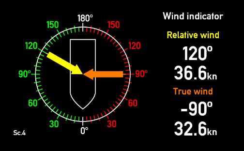
61 Virtual Indicator - 5 Relative, true and geographical wind forward, 4 screens Screen 1 Screen 2 Screen 3 Screen 4 Virtual Indicator - 6 Relative, true and geographical wind aft, 4 screens Screen 1 Screen 2 Screen 3 Screen 4 DEIF A/S Page 61 of 66


62 Virtual Indicator - 7 Relative, true and geographical wind forward, 4 screens Screen 1 Screen 2 Screen 3 Screen 4 Virtual Indicator - 8 Relative, true and geographical wind aft, 4 screens Screen 1 Screen 2 Screen 3 Screen 4 DEIF A/S Page 62 of 66
INSTALLATION INSTRUCTIONS AND REFERENCE HANDBOOK
 INSTALLATION INSTRUCTIONS AND REFERENCE HANDBOOK APPLICATION NOTES WIND MEASURING SYSTEMS Document no.: 4189340577BC SW version AGC 3.4X0.X0 or later and AGC 4.00.0 or later Document no.: 4189350050A Table
TECNAUTIC_GmbH. Display Functions with the PB100/200 connected: -- GND Speed -- GND Course -- Heading (Gyro option is recommended) 2 m
 2 m") PB100/200 Sonic Wind Wind, GPS, Compass Display Config: SE=12 di=00 df=20,91,30,34,(61) 35,36,81 Gr=01 n0=00 n1=07 n2=07**) n3=00 Display Functions with the PB100/200 connected: -- Apparent Wind -- True
PB100/200 Sonic Wind Wind, GPS, Compass Display Config: SE=12 di=00 df=20,91,30,34,(61) 35,36,81 Gr=01 n0=00 n1=07 n2=07**) n3=00 Display Functions with the PB100/200 connected: -- Apparent Wind -- True
APPLICATION NOTES DELOMATIC 4, DM-4 GAS
 APPLICATION NOTES DELOMATIC 4, DM-4 GAS Emission control Lambda sensor p/t regulation Combustion chamber temperature regulation Emission control configuration Emission control curve Document no.: 4189340653C
PART 5 - OPTIONS CONTENTS 5.1 SYSTEM EXPANSION 5-3
 PART 5 - OPTIONS CONTENTS Para Page 5.1 SYSTEM EXPANSION 5-3 5.2 SENSORS 5-3 5.2.1 Trim Angle Sensor 5-3 5.2.2 Mast Rotation Sensor 5-3 5.2.3 Heel Angle Sensor 5-3 5.2.4 Barometric Pressure Sensor 5-3
GNX 20/21. Owner s Manual
 GNX 20/21 Owner s Manual Table of Contents Introduction...1 Device Overview... 1 Using the Race Timer... 1 Profiles... 1 Selecting a Profile... 1 Restoring Profiles to their Default Settings... 1 Instrument
Manual Weighingblock VB2 series and Uniscale
 Manual Weighingblock VB2 series and Uniscale Note: At page 8 in this manual you will find a short form instruction. Normally the only instruction shipped together with the Scale. Overview different ranges.
Oxygen Meter User Manual
 Oxygen Meter User Manual Monday, July 23, 2007 1. Outline...2 2. Program...3 2.1. Environment for program execution...3 2.2. Installation...3 2.3. Un installation...3 2.4. USB driver installation...3 2.5.
GNX 20/21. Owner s Manual
 GNX 20/21 Owner s Manual March 2016 190-01659-00_0C All rights reserved. Under the copyright laws, this manual may not be copied, in whole or in part, without the written consent of Garmin. Garmin reserves
iregatta User Manual
 iregatta User Manual iregatta User Manual This manual may not always be up to date with the latest version of iregatta available in Apples App Store, as minor additions or bug fixes may be published without
OMC-140 Multifunctional NMEA display. Operators Manual. Version Author: Observator Instruments
 OMC-140 Multifunctional NMEA display Operators Manual Version 1.04-2015 Author: Observator Instruments Revisions: 1.01 July 2014 First issue 1.02 Oct 2014 Preliminary edition 1.03 April 2015 Test Manual
LX Compass module 3 Electronic compass device User manual
 LX Compass module 3 Electronic compass device User manual LX navigation d.o.o., Tkalska 10 SLO 3000 Celje, tel: + 386 3 490 46 70, fax: + 386 3 490 46 71 info@lxnavigation.si, http://www.lxnavigation.com
Domino DUEMMEGI. Domino. Communication Interface DFTS User s Manual. Release September 2007
 Domino Domino Communication Interface DFTS User s Manual Release 2.3 - September 2007 srl Via Longhena 4-20139 MILANO Tel. 02/57300377 - FAX 02/55213686 Domino - DFTS: User s Manual R.2.3 Index 1- INTRODUCTION...3
BUYER S GUIDE AQUAlogger 530WTD
 OCEAN & ENVIRONMENTAL BUYER S GUIDE AQUAlogger 530WTD Wireless Temperature and Depth Logger AQUAlogger 530WTD The AQUAlogger 530WTD has an innovative design that includes the ability to transfer stored
INTRODUCTION TO NETWORK WIND 3 MOUNTING THE UNIT 14 SELECTING THE DISPLAY MODE 5 ABBREVIATIONS AND DEFINITIONS 17
 CONTENTS CONTENTS 1 INSTALLATION 14 GENERAL INTRODUCTION TO B&G NETWORK 2 SITING THE UNIT 14 INTRODUCTION TO NETWORK WIND 3 MOUNTING THE UNIT 14 EXAMPLE SYSTEMS USING NETWORK WIND 4 SPECIFICATION 16 SELECTING
GNX 120/130. Owner s Manual
 GNX 120/130 Owner s Manual March 2016 190-01846-00_0B All rights reserved. Under the copyright laws, this manual may not be copied, in whole or in part, without the written consent of Garmin. Garmin reserves
Pneumatic high-pressure controller Model CPC7000
 Calibration technology Pneumatic high-pressure controller Model CPC7000 WIKA data sheet CT 27.63 Applications Healthcare and avionics industry Industry (laboratory, workshop and production) Transmitter
USER MANUAL. Intelligent Diagnostic Controller IDC24-A IDC24-AF IDC24-AFL IDC24-F IDP24-A * IDP24-AF * IDP24-AFL * IDP24-F * 1/73
 USER MANUAL Intelligent Diagnostic Controller IDC24-A IDC24-AF IDC24-AFL IDC24-F IDP24-A * IDP24-AF * IDP24-AFL * IDP24-F * *) Require software ID: DID-SW-001 1/73 Table of contents 1 General... 3 1.1
Remote Control Bait Boat
 CARPIO 2.0 User Manual All pictures shown are for illustration purpose only. Actual product may vary due to product enhancement Remote Control Bait Boat (Smart Remote Control at 868 MHz) 1 Table of Contents
BUBBLER CONTROL SYSTEM
 BUBBLER CONTROL SYSTEM Description: The HDBCS is a fully automatic bubbler system, which does liquid level measurements in water and wastewater applications. It is a dual air compressor system with, air
GNX 20/21 Owner s Manual
 GNX 20/21 Owner s Manual February 2014 190-01659-00_0B Printed in Taiwan All rights reserved. Under the copyright laws, this manual may not be copied, in whole or in part, without the written consent of
Product Overview. Product Description CHAPTER
 CHAPTER 1 This chapter provides a functional overview of the Cisco Redundant Power System 2300 and covers these topics: Product Description, page 1-1 Features, page 1-3 Supported Devices, page 1-4 Deployment
Autopilot setup. VRF (Virtual Rudder Feedback) calibration. Software setup NSS evo2 Installation Manual
 calibration. Software setup NSS evo2 Installation Manual") Autopilot setup Verifying the autopilot connection When an AC12N, AC42N, or SG05 is connected to the NSS evo2 system, the NSS evo2 will automatically detect the autopilot and an Autopilot menu icon will
Autopilot setup Verifying the autopilot connection When an AC12N, AC42N, or SG05 is connected to the NSS evo2 system, the NSS evo2 will automatically detect the autopilot and an Autopilot menu icon will
GasSense NDIR User Manual
 INDEX INDEX... 1 1. OVERVIEW... 2 2. TECHNICAL DATA... 3 3. SPECIFICATIONS... 4 4. PRODUCT DESCRIPTION... 5 4.1 Mechanical details... 5 4.2 Piping... 7 4.3 Connections... 7 5. INSTALLATION... 10 6. CALIBRATION
FTC130 Transmitter. Operating Manual
 Seite 1 von 11 FTC130 Transmitter Fast Thermal Conductivity Analyzer Operating Manual 1.09KD180724CWI1V05 Messkonzept GmbH Seite 2 von 11 1. Intended Use... 3 2. Description... 4 3. Measuring gases and
Introduction. The Shearwater Petrel is an advanced technical diving computer for open and closed circuit divers.
 Introduction The Shearwater Petrel is an advanced technical diving computer for open and closed circuit divers. Although we strive to make the Petrel easy enough to use without reading the manual, please
SCIENTIFIC DATA SYSTEMS, INC. Depth Tension Line Speed Panel. DTLS Manual
 SCIENTIFIC DATA SYSTEMS, INC. Depth Tension Line Speed Panel DTLS Manual This document contains proprietary information. Copyright 2015 Scientific Data Systems, Inc. All rights reserved. 1 Depth Tension
CONSOLE-320 ENGLISH. 230A: CONSOLE-320 with cable data output Item 230B: CONSOLE-320 with cable + wireless radio data output
 CONSOLE-320 Item 230A: CONSOLE-320 with cable data output Item 230B: CONSOLE-320 with cable + wireless radio data output Table of contents 1. INTRODUCTION...2 1.1 Power supply...2 1.2 Connections...2 1.3
Sail Racing Instruments. Aspect 40
 Sail Racing Instruments www.nexusmarine.se Presentation Nexus Marine is a leading manufacturer of navigation instrumentation for racing and cruising yachts. Nexus brings with it seventy years of experience
Stand-Alone Bubble Detection System
 Instruction Sheet P/N Stand-Alone Bubble Detection System 1. Introduction The Bubble Detection system is designed to detect air-bubble induced gaps in a bead of material as it is being dispensed. When
WMB-160F Multi-beam Fishing System
 WMB-160F Multi-beam Fishing System Take away the guess work and see what s REALLY below your boat! Seven Systems in One 2 WMB-160F WMB-160F Screen Shots The WMB-160F is a multi-beam sonar that has been
Doppler current meter
 JLN-652 Doppler current meter JRC's new 240 khz Doppler current meter: the smartest way to increase your catch Unique 3D twist mode presentation Measuring up and down current 50 independent measuring layers
TOP BLEED Position for SeaTalk 2 colour logo ST 30. COMPASS Operation and Installation
 Distributed by Any reference to Raytheon or RTN in this manual should be interpreted as Raymarine. The names Raytheon and RTN are owned by the Raytheon Company. TOP BLEED Position for SeaTalk 2 colour
Steer to Wind angle, Wind Mode, when connected to the h1000 Wind Interface
 h1000 pilot introduction overview Congratulations on your purchase of the h1000 Pilot from B&G. The h1000 Pilot is the latest in autopilots from B&G and represents B&G s commitment to providing our customers
SC 110 Autopilot Installation and Operations Manual _A
 SC 110 Autopilot Installation and Operations Manual 531760-3_A Thank You Thank you for choosing Humminbird, the #1 name in Fishfinders. Humminbird has built its reputation by designing and manufacturing
AP48. Operator Manual. ENGLISH
 AP48 Operator Manual ENGLISH www.simrad-yachting.com Preface Disclaimer As Navico is continuously improving this product, we retain the right to make changes to the product at any time which may not be
OMNISPORT 2000 SWIMMING QUICK REFERENCE
 Before During After OMNISPORT 2000 SWIMMING QUICK REFERENCE 1. Confirm that the timer is reset. 2. Set the timer to the correct event and heat. The right LCD, line 2 displays E:(event) H:(heat) R:(round)
BI-680 Online Dissolved Oxygen Controller Instruction Manual
 BI-680 Online Dissolved Oxygen Controller Instruction Manual BANTE INSTRUMENTS CO., LTD BI-680 Online Dissolved Oxygen Controller 1 Introduction Thank you for selecting the BI-680 online dissolved oxygen
Helium Level Measurement Unit
 Helium Level Measurement Unit HLMU User Manual Version 002 The information in this manual may be altered without notice. BRUKER BIOSPIN accepts no responsibility for actions taken as a result of use of
Air Bubbler Depth Gauge DG2200 Installation and Reference Manual
 Air Bubbler Depth Gauge DG2200 Installation and Reference Manual Rev. 3.2.2 06/2011 Installation and Reference Manual Page 2 Contents Chapter 1: Installation and Overview... 3 1.1 DG2200 Location Diagram...
Ultrasonic Wind Sensor
 CV7-L Ultrasonic Wind Sensor Page 1 of 8 1. Installation Prepare the mast head for the mechanical installation. Use the template for the bracket s screwing. Align the bracket in order to have the CV7-L
A TECHNICAL REFERENCE
 A TECHNICAL REFERENCE FOR CAREL DCM CONTROLLERS DIGITAL COMPRESSOR MODULE CANADIAN HEAD OFFICE AND FACTORY USA HEAD OFFICE AND FACTORY CANADIAN EASTERN FACTORY 1401 HASTINGS CRES. SE CALGARY, ALBERTA T2G
Optical Dissolved Oxygen Meter
 Optical Dissolved Oxygen Meter HI764113 Rugged Optical Dissolved Oxygen Probe for Fresh and Saltwater Applications Digital, weighted probe No membranes No electrolytes No oxygen consumption No flow dependence
955730_1 4/17/18. FlowSense Operator s Guide For Gen2 20/20 SeedSense Displays
 955730_1 4/17/18 FlowSense Operator s Guide For Gen2 20/20 SeedSense Displays Contents System Setup and Operation...3 Configuring Monitor for FlowSense...3 FlowSense Setup...4 Liquid Alerts...8 Monitoring
Explorer AP380 Autopilot Installation and Operation Manual
 Explorer AP380 Autopilot Installation and Operation Manual www.northstarnav.com IMPORTANT SAFETY INFORMATION Please read carefully before installation and use. DANGER! WARNING! CAUTION CAUTION This is
Ultrasonic Wind Sensor
 CV7-EL Ultrasonic Wind Sensor Page 1 of 8 1. Installation Prepare the mast head for the mechanical installation. Use the template for the bracket s screwing. Align the bracket in order to have the CV7-EL
TEL/jlRE" Introduction. Display Features and Modes. Startup Procedure. Power-Up Procedure. Adjustment Modes
 TEL/jlRE" Introduction The Telaire 7001 CO 2 /T emperature monitor (shown in Fi gt u e 1 below) is an easy to use hand-held instnunent, which provides stable and highly accurate readings due to Telaire
Sensoric 4-20 ma Transmitter Board Operation Manual
 Sensoric 4-20 ma Transmitter Board Operation Manual 1 Content Features Operation Manual Technical Data Mechanical Dimensions Remarks & Contact information 2 Features Soldered sensor cell (non replaceable)
UBEC 1AT. AUTO TANK Fill System Installation, Operation, & Setup Instructions
 Document Number: XE-ATA5PM-R1A UBEC 1AT AUTO TANK Fill System 08899155 Installation, Operation, & Setup Instructions Rev170906-EB-FRC PHYSICAL: 1302 WEST BEARDSLEY AVE ELKHART, IN 46514 WWW.ELKHARTBRASS.COM
ECL Comfort 110, application 131 (valid as of software version 2.00)
") Operating Guide ECL Comfort 110, application 131 (valid as of software version 2.00) English version www.danfoss.com How to navigate? Adjust temperatures and values. Switch between menu lines. Select /
Operating Guide ECL Comfort 110, application 131 (valid as of software version 2.00) English version www.danfoss.com How to navigate? Adjust temperatures and values. Switch between menu lines. Select /
STARLOG. Capacitive Water Depth Probe
 STARLOG Capacitive Water Depth Probe Model 6521 User Manual Supplement 6219 Revision D July 10. 1998 Copyright Notice Copyright Unidata Australia 1998. All rights reserved. No part of this publication
Temperature Controller CC24-7 ULTRA USER S MANUAL Legion Dr. Mason, MI USA October 2010 Ph. (517) Fax (517)
 Fax (517)") Temperature Controller USER S MANUAL Aerotech, Inc. FORM: QM1387 4215 Legion Dr. Mason, MI 48854-1036 USA October 2010 Ph. (517) 676-7070 Fax (517) 676-7078 FOR CUSTOMER USE Enter the serial number located
Temperature Controller USER S MANUAL Aerotech, Inc. FORM: QM1387 4215 Legion Dr. Mason, MI 48854-1036 USA October 2010 Ph. (517) 676-7070 Fax (517) 676-7078 FOR CUSTOMER USE Enter the serial number located
SP-110 Autopilot OPERATION
 SP-110 Autopilot OPERATION www.si-tex.com Warning! WHEN USING THE AUTOPILOT AN ADEQUATE WATCH SHOULD BE MAINTAINED AT ALL TIMES. THE AUTOPILOT MUST BE PLACED IN MANUAL MODE WHEN EVER THE VESSEL IS STATIONARY
OC508 Programmable mv Calibrator
 OC508_GBM_201609 OC508 Programmable mv Calibrator Owner s Manual Orbit Controls AG Zürcherstrasse 137 CH8952 Schlieren - ZH orbitcontrols.ch OC508 Programmable mv Calibrator Selection of DIN Thermocouples
Operating Manual. SUPREMA Calibration. Software for Fire and Gas Warning Units. Order No.: /01. MSAsafety.com
 Operating Manual Software for Fire and Gas Warning Units Order No.: 10154656/01 MSAsafety.com MSA Europe GmbH Schlüsselstrasse 12 8645 Rapperswil-Jona Switzerland info.ch@msasafety.com www.msasafety.com
Electronic gas volume corrector model DGVC-04
 Electronic gas volume corrector model DGVC-04 1. Introduction The following user s manual gives information about the installation, configuration, usage and storage of the electronic gas volume corrector
ELIMINATOR COMPETITION DRAG RACE Program Manual Firm Ver 4.11
 ELIMINATOR COMPETITION DRAG RACE Program Manual Firm Ver 4.11 The Portatree Eliminator Super 2000 Competition Track Timer can be used with an IBM Compatible Personal Computer connected through Com Port
BUBBLER CONTROL SYSTEM
 BUBBLER CONTROL SYSTEM Description: The LDBCS is a fully automatic bubbler system, which does liquid level measurements in water and wastewater applications. It is a dual air compressor system with, air
GHC 20. Owner s Manual
 GHC 20 Owner s Manual 2013 Garmin Ltd. or its subsidiaries All rights reserved. Under the copyright laws, this manual may not be copied, in whole or in part, without the written consent of Garmin. Garmin
2. USER INSTRUCTION. Table of contents: Pg.1/14 N:\FAP-2000: LWP
 Pg.1/14 2. USER INSTRUCTION. Table of contents: 2.1 SHORT PANEL DESCRIPTION...... Pg.2 2.2 AUTOPILOT TAKE-OVER & MODE SELECTION....... Pg.3 2.3 AUTOPILOT FUNCTIONS....... Pg.3 2.4 THE SPECIAL FUNCTION
WeatherStation Powerboat Model PB100 Owner s Guide
 WeatherStation Powerboat Model PB100 Owner s Guide Record the serial number found on the WeatherStation for future reference. Serial No. Date of Purchase 17-426-01 r01 02/01/06 Copyright 2005, 2006 Airmar
WELCOME TO THE REVOLUTION
 USER GUIDE WELCOME TO THE REVOLUTION THANK YOU FOR CHOOSING THE GCQUAD We listened to what you wanted - and created the most accurate, versatile and game-enhancing ball and club analysis solution available
GNX Wind. Owner s Manual
 GNX Wind Owner s Manual February 2016 190-02003-00_0A All rights reserved. Under the copyright laws, this manual may not be copied, in whole or in part, without the written consent of Garmin. Garmin reserves
Mass Flow Controller (MFC) for Gases
 for Gases") Mass Flow Controller (MFC) for Gases Type 8713 can be combined with... Direct flow measurement by MEMS- Technology for nominal flow rates from 1 ml N /min to 8 l N /min (N 2 ) High accuracy and repeatability
Mass Flow Controller (MFC) for Gases Type 8713 can be combined with... Direct flow measurement by MEMS- Technology for nominal flow rates from 1 ml N /min to 8 l N /min (N 2 ) High accuracy and repeatability
MANUAL. P C - C E N T E R Version Copyright by Dinand van het Reve CONTENTS
 P C - C E N T E R Version 4.00 Copyright 1995-2004 by Dinand van het Reve CONTENTS 1. Introduction 2. Installing PC-CENTER 3. Licence 4. Using PC-CENTER 5. Description of 'Small Windows' 6. Main Menu Description
Pneumatic high-pressure controller Model CPC7000
 Calibration technology Pneumatic high-pressure controller Model CPC7000 WIKA data sheet CT 27.63 Applications Automotive and avionics industry Industry (laboratory, workshop and production) Transmitter
Operating instructions Safety Rope Emergency Stop Switches ZB0052 / ZB0053 ZB0072 / ZB0073
 Operating instructions Safety Rope Emergency Stop Switches UK ZB0052 / ZB0053 ZB0072 / ZB0073 7390878 / 02 03 / 2011 Contents 1 Safety instructions...3 2 Installation / set-up...4 2.1 Applications...4
Digi Connect ME 9210 Linux: 2 nd serial over FIM
 Digi Connect ME 9210 Linux: 2 nd serial over FIM Document History Date Version Change Description 09/04/2009 Initial entry/outline Table of Contents Document History... 2 Table of Contents... 2 1 Problem
MANUAL. Simrad AP26 and AP27 Autopilots
 MANUAL Simrad AP26 and AP27 Autopilots This page is intentionally left blank Instruction manual Instruction Manual This manual is intended as a reference guide for operating and correctly installing the
Pilot 3380 A U T O P I L O T. Operation Manual NAVMAN
 Pilot 3380 A U T O P I L O T Operation Manual w w w. n a v m a n. c o m NAVMAN FCC Statement Note: This equipment has been tested and found to comply with the limits for a Class B digital device, pursuant
MP15 Jockey Pump Controller
 Setup and Operating Instructions MP15 Jockey Pump Controller This manual provides general information, installation, operation, maintenance, and system setup information for Metron Model MP15 Jockey Pump
mn100 Analog Display
 mn100 Analog Display uu040 rev. 8 mn100 Analog Display EMC Conformance All Tacktick equipment is designed to the best industry standards for use in the recreational marine environment. The design and manufacture
Napa Technology Trouble Shooting. For Premier & Premier PLUS Models
 Napa Technology Trouble Shooting For Premier & Premier PLUS Models Before contacting Napa Technology for support, please check if the problem and solution are found below: Machine Is Off & All LCD s are
OPERATION AND INSTALLATION MANUAL
 AP46 Autopilot OPERATION AND INSTALLATION MANUAL www.tmq.com.au TMQ AP46 Autopilot Page 1 of 34 Ver1.0 07/03/2007 This page is Blank TMQ AP46 Autopilot Page 2 of 34 Ver1.0 07/03/2007 WARNING!...4 INTRODUCTION...5
Optical Dissolved Oxygen Meter
 Optical Dissolved Oxygen Meter HI764113 Rugged Optical Dissolved Oxygen Probe for Fresh and Saltwater Applications Digital probe Fast and stable readings No membranes Not affected by sunlight No electrolytes
WATER CONTROL SYSTEM QUICK START
 SETTINGS MENU SYSTEM OPTIONS WATER LEVEL BAR GRAPH 3 DS SPRAY ON/OFF CS SPRAY ON/OFF BEACON WATER CONTROL SYSTEM QUICK START WWW.GFWORLDWIDE.COM +1 (208) 664-9291 SERVICE@GFWORLDWIDE.COM DISPLAY SCREEN
Model GFC 7000T CO 2 Analyzer (Addendum to GFC 7000TA Manual, PN 07272)
") Manual Addendum Model GFC 7000T CO 2 Analyzer (Addendum to GFC 7000TA Manual, PN 07272) P/N M07273 DATE 06/11/13 TELEDYNE ELECTRONIC TECHNOLOGIES Analytical Instruments 16830 Chestnut Street City of Industry,
Manual Addendum Model GFC 7000T CO 2 Analyzer (Addendum to GFC 7000TA Manual, PN 07272) P/N M07273 DATE 06/11/13 TELEDYNE ELECTRONIC TECHNOLOGIES Analytical Instruments 16830 Chestnut Street City of Industry,
Quickstart Installation Checklist (Please refer to operation manual for complete installation instructions)
") Quickstart Installation Checklist (Please refer to operation manual for complete installation instructions) 1. Uncrate blender from packaging. 2. Lift the blender and position over machine throat or floor
Quickstart Installation Checklist (Please refer to operation manual for complete installation instructions) 1. Uncrate blender from packaging. 2. Lift the blender and position over machine throat or floor
USER GUIDE FOR DATALINE-X SDX. Stowe Marine Ltd. Tel +44(0)
") USER GUIDE FOR DATALINE-X SDX Stowe Marine Ltd. www.stowemarine.com Tel +44(0)1590 610071 Dataline-X SDX Manual, Part Number 05707SM, Issue 2, Dec 1995. Warning The equipment to which this manual applies
USER GUIDE FOR DATALINE-X SDX Stowe Marine Ltd. www.stowemarine.com Tel +44(0)1590 610071 Dataline-X SDX Manual, Part Number 05707SM, Issue 2, Dec 1995. Warning The equipment to which this manual applies
Race Screen: Figure 2: Race Screen. Figure 3: Race Screen with Top Bulb Lock
 Eliminator Competition Stand Alone Mode - Instruction Manual Main Menu: After startup, the Eliminator Competition will enter the Main Menu. Press the right/left arrow buttons to move through the menu.
AP44. Operator Manual. ENGLISH
 AP44 Operator Manual ENGLISH www.simrad-yachting.com Preface Disclaimer As Navico is continuously improving this product, we retain the right to make changes to the product at any time which may not be
APA software instruction manual
 1. Starting the program In order to start the control software for the APA device press APAxx shortcut located on the desktop of the supplied computer. XX corresponds to the current software version. When
Navico. Software Release Notes H5000 RTM 2018 SOFTWARE RELEASE JULY Photo: Rich Edwards/Volvo Ocean Race H5000 INSTRUMENTS AUTOPILOT
 Software Release Notes H5000 RTM 2018 SOFTWARE RELEASE JULY 2018 Photo: Rich Edwards/Volvo Ocean Race H5000 INSTRUMENTS AUTOPILOT Overview The latest H5000 developments provide a system-wide package of
h1000 system user manual
 h1000 system user manual HB-1000D Issue: 0001 h1000 introduction overview Congratulations on your purchase of the h1000 System from B&G. The h1000 navigation system combines clever thinking with incredibly
WIND CLIPPER KTS ILLUM SCALE INC DEC CLIPPER WIND SYSTEM
 CLIPPER WIND KTS ILLUM SCALE DEC INC CLIPPER WIND SYSTEM TABLE OF CONTENTS INTRODUCTION PRE-TEST OF INSTRUMENT INSTALLING THE MASTHEAD SENSOR UNIT INSTALLING THE DISPLAY NORMAL OPERATION CHANGING THE
Scoreboard Operator s Instructions MPC Control
 Scoreboard Operator s Instructions MPC Control Some features on the keyboard overlay may not be included on the particular model being operated. Since 1934 Retain this manual in your permanent files 1/21/2011
Technical Data Sheet MF010-O-LC
 Technical Data Sheet MF010-O-LC - 1 - 1. Properties The oxygen measuring system MF010-O-LC determines the oxygen content in gas mixtures up to a temperature of 250 C. It is particularly suitable for the
AP60 Operator Manual ENGLISH
 AP60 Operator Manual ENGLISH Preface Disclaimer As Navico is continuously improving this product, we retain the right to make changes to the product at any time which may not be reflected in this version
FireHawk M7 Interface Module Software Instructions OPERATION AND INSTRUCTIONS
 FireHawk M7 Interface Module Software Instructions OPERATION AND INSTRUCTIONS WARNING THE WARRANTIES MADE BY MSA WITH RESPECT TO THE PRODUCT ARE VOIDED IF THE PRODUCT IS NOT USED AND MAINTAINED IN ACCORDANCE
REASONS FOR THE DEVELOPMENT
 7 Series 7 Series +24VDC VDC OUTPUT MICROPROCESS. E P IN EXH OUT 7 Series 7 ø,8 8 7 Series 9 5 8 9 7 Series Display features The proportional regulator has a 3 /2 digit display and a three-pushbutton
D-Opto Dissolved Oxygen Sensor Operation Manual for the D-Opto 4-20mA
 D-Opto Dissolved Oxygen Sensor Operation Manual for the D-Opto 4-20mA Software version 2.6 Table of contents 1 Introduction...3 1.1 Optical Sensor Technology...3 1.2 Installation...4 1.3 Operation...5
RG2 Gripper Datasheet Version 1.6
 RG2 Gripper Datasheet Version 1.6 The RG2 gripper is a flexible electric gripper specially designed for robots from Universal Robots. The long stroke allows the gripper to handle a variety of object sizes.
IBU3 Manual Addendum 1
 This addendum covers the follow items. Connection of airsoft micro switch Connection of Taigen airsoft recoil units Selecting airsoft mode Settings for clutch style gearboxes Motor enable selection Confirmation
GHC 20 Owner s Manual
 GHC 20 Owner s Manual Introduction See the Important Safety and Product Information guide in the product box for product warnings and other important information. You are responsible for the safe and prudent
PTG100 Precision Test Gauge
 PTG100 Precision Test Gauge User Manual PD1007 Rev B 03/28/2014 Palmer Instruments Inc. 234 Old Weaverville Road Asheville, NC 28804 Toll Free: 800-421-2853 Phone: 828-658-3131 Fax: 828-658-0728 Email:
Do Not Print This Page.
 Do Not Print This Page. Load 1 sheet of cardstock paper. Print Page 2 - the cover For the body of the text, load 3 sheets of 28lb matte finish paper into the printer. Print pages 3, 5, 7 (Sheet 1, 2, 3)
The HumiSys. RH Generator. Operation. Applications. Designed, built, and supported by InstruQuest Inc.
 The HumiSys RH Generator Designed, built, and supported by InstruQuest Inc. Versatile Relative Humidity Generation and Multi-Sensor System The new HumiSys with single or dual RH probes capabilities is
Mass Flow Controller (MFC) for Gases
 for Gases") Mass Flow Controller (MFC) for Gases Direct flow measurement with CMOSens technology for nominal flow rates from 0 ml N to 0 l N High accuracy and reproducibility Ingress protection IP Type can be combined
Mass Flow Controller (MFC) for Gases Direct flow measurement with CMOSens technology for nominal flow rates from 0 ml N to 0 l N High accuracy and reproducibility Ingress protection IP Type can be combined
Basic Nitriding Sampling System Hydrogen Analyzer with Calculated % DA, % NH 3, and K N Values. Operations Manual
 Basic Nitriding Sampling System Hydrogen Analyzer with Calculated % DA, % NH 3, and K N Values Operations Manual Please read, understand, and follow these instructions before operating this equipment.
Additel 761 Automated Pressure Calibrators Selection Guide
 / Process Calibration Equipment Automated Calibrators Selection Guide Model Features Range Module 1 761-LLP 761-D 761-L 761-LA 761-M 761-MA 761-H 761-HA 761-BP -2.5 to 2.5 mbar (-1 to 1 inh 2 O) -0.95
Hydro-Control V User Guide
 Hydro-Control V User Guide Hydronix Part no: HD0193 Version 2.3.0 Revision date: July 2006 1 COPYRIGHT Neither the whole or any part of the information contained in nor the product described in this documentation