Step 1: Block sand the transom to remove the seam joint. The end result should be a flat transom without a ledge where the seam joint is.
|
|
|
- Hollie Kelley
- 5 years ago
- Views:
Transcription


1 WhiplashGV Instruction Manual Phone: Step 1: Block sand the transom to remove the seam joint. The end result should be a flat transom without a ledge where the seam joint is. Step 2: Place the boat on a flat surface and draw a perpendicular line from the flat surface at the middle of the transom. DO NOT make the line perpendicular to the bottom of the boat.


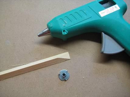
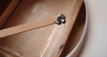
2 Step 2 continued Turn the boat upside down, place a straight edge from sponson to sponson and draw a perpendicular line on the outside of the sponson. DO NOT make the line perpendicular to the bottom of the boat. Step 3: Line up the turnfin bracket angle to the line you just made on the sponson. Place the angle 3/16 above the bottom of the sponson and drill one hole only. Glue a #10 blind nut to the end of a stick with a hot glue gun and feed the nut to the hole. From the outside of the boat, use a #10 screw to pull the blind nut into the interior wood backing. Once the first blind nut is installed, secure the angle to the boat, and then match drill the other hole, making sure the angle is parallel with the line drawn in step 2. Secure the second #10 blind nut.
3


4 After both holes are drilled and both blind nuts are installed, remove the bracket and slot the upper hole. The upper slot will enable the bracket to rotate about the bottom pivot point. A good starting angle for the fin is a difference of 1/8 measured from the bottom of the sponson. The more you angle the fin in, the more responsive the boat will be in the turns, but the more likelihood of a blow over if a left turn is made. Angle the fin to suit your driving style. Step 4: Mount the Speedmaster VM4R Round Bottom Strut in the center of the transom. Mount the Speedmaster Rudder on the left side or right side of the strut. Step 5: Engine placement is 26-3/4 measured from the transom to the center of the spark plug. Place a ¼ shim under the cullet side of the engine, and 1/8 shim under the pull start side of the engine. Use blind nuts on the outside of the engine walls to secure the mounts. You may find it necessary to sand away the fiberglass tape which secures the engine walls to the hull in order to fit the engine.


5 Step 6: Estimate where the shaft would go thru the stuffing box and drill an 11/32 diameter hole at this location. Place a 4 long piece of 11/32 diameter tubing over a long piece of 5/16 dia tubing which goes from the cullet thru the strut. Bend the 5/16 dia tubing so it matches up perfectly with the angle of the engine. Once the alignment is perfect, seal any gaps between the stuffing box and the 11/32 diameter tube using a hot glue gun. Turn the boat upside down and fill the stuffing box with epoxy. Be sure to roughen up the 11/32 diameter tube and the inside of the stuffing box so the epoxy sticks.

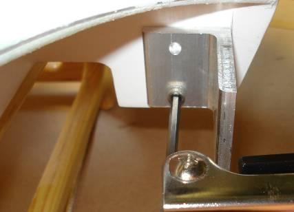
6 Step 7: Use a high torque standard size servo for the steering, and a standard torque servo for the throttle. You can either make wood blocks to screw the servos down, or use servo mounts as shown to mount the servos. The servos must be flat on the bottom of the radio box so the servo arms clear the top of the lid.

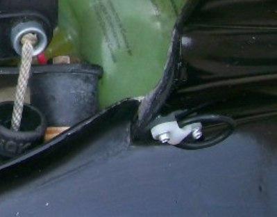
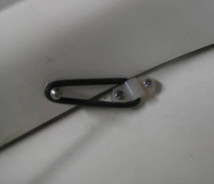
7 Step 8: Use a 90 degree header coming off the engine. The pipe should be secured to the deck using an angle and a hose clamp. There is a block of wood glued under the deck to mount the angle. Use bolts and nuts to secure the bracket to the deck. Step 9: To secure the cowl to the hull, use two nylon straps in the front, and one in the rear. Screw the nylon straps to the hull, and bolt steel ball links to the cowl. The front two ball links should be placed on the cowl so they pull the cowl forward and down at the same time. The rear ball link should pull the cowl forward and down. Position the rear nylon strap next to the cowl so it aligns the cowl in the center of the boat.
8 .


9 Step 10: Cut an opening in the cowl for the sparkplug and the header. Cut an air intake hole in the cowling towards the rear of the carburetor to ensure fresh air goes into the engine. Setup: Rudder Length o Cut the rudder length so it measures 3 from the leading tip of the rudder to the bottom of the transom. Cut the rudder so it tapers up in the back to decrease lift caused by the rudder.
 Turnfin Adjustment o o The bottom of the turnfin should be 2-3/8 from the bottom of the fin to the bottom of the sponson.")
10 Strut Depth o Position the round bottom strut flat, measuring 1 from the bottom of the boat to the bottom of the strut. Strut should be flat, or a touch positive (to raise the bow) Turnfin Adjustment o o The bottom of the turnfin should be 2-3/8 from the bottom of the fin to the bottom of the sponson. Place a straight edge on the inside of the turnfin. The straight edge should be parallel with the inside sponson. Add a shim between the turnfin bracket and the hull to make adjustments if necessary. A good starting point for the turnfin angle (front to back) is to make it parallel with the bottom of the boat. In testing, we had to angle the fin about 1/8 forward to get the nose to carry. If the boat is too tight on the water, push the fin forward. If the boat is too loose on the water, pull the fin back. Fuel Tank Placement o Fuel tank should be placed in the nose. I personally use a 500cc IV bag. Props o We have tested numerous props, and 3 have stood out. Regardless what prop you end up using, the prop should have the LEAST amount of lift possible. Propshop 7018/2 #445 from Bob Austin Propshop 6719/3, #567 from Bob Austin Propshop 6719/3, from Chris Hoffman
Blazer Marine, Whiplash Sport Hydro
 Blazer Marine, Whiplash Sport Hydro Thank you for choosing to build the Whiplash Sport Hydro. We have spent over 12 years perfecting this design, and finally we are making it available to the world. We
SEADUCER BOATS GAS SPORT HYDRO
 SEADUCER BOATS GAS SPORT HYDRO COME VISIT US ON THE WEB AT WWW.SEADUCERBOATS.COM 2 - Pkg. Of 440 push rod ends 2 - Pkg. of solder-on rod ends 2 -water outlet fitting 1-1/4" prop nut 1 -.250" x 30" flex
Blazer Marine, Whiplash Sport 40
 Blazer Marine, Whiplash Sport 40 Thank you for choosing to build the Whiplash 40. We have spent over 12 years perfecting this design, and finally we are making it available to the world. We are excited
SEADUCER BOATS GAS MONO COME VISIT US ON THE WEB AT
 SEADUCER BOATS GAS MONO COME VISIT US ON THE WEB AT WWW.SEADUCERBOATS.COM 1 - Pkg. Of 440 push rod ends 1 - Pkg. of solder-on rod ends 2 -water outlet fitting 1-1/4" prop nut 1 -.250" x 24" flex shaft
1/10 th Scale 1956 Ted Jones Classic Hydroplane
 1/10 th Scale 1956 Ted Jones Classic Hydroplane Preparation These plans show outside sheeting of 3/32 balsa laminated with 1/64 birch ply. This makes a light and strong skin for this boat. Optionally you
Riviera Draft Shaft Hole Boring
 Riviera Draft Shaft Hole Boring a. Height from bottom of hull thru the hull to the center of the drive shaft. This will be calculated. b. Height of drop of strut. The strut for the Riviera is 7.5 c. Distance
BUILDING INSTRUCTIONS
 Z I P P M A N U FA C T U R I N G A Zippkits R/C Boat BUILDING INSTRUCTIONS 2010 Zipp Manufacturing Frankfort, New York 13340 www.zippkits.com Table of Contents Introduction 1 Engine Mounting 30 S E C T
PAY N PAK, 1/12 th Scale, Limited Sport Hydro P Sport Hydro
 1980 82 PAY N PAK, 1/12 th Scale, Limited Sport Hydro P Sport Hydro Introduction: The 1980 turbine Pay N Pak is a good subject for a model race boat. It has a low profile, mild pickle-fork setback, long
SLR Missile Thunderboat
 J M P H O B B Y G R O U P L L C SLR Missile Thunderboat Zippkits R/C Boats BUILDING INSTRUCTIONS 2017 JMP Hobby Group LLC Indiana USA 1 Introduction Thank you for purchasing this kit. We are sure that
Constitution Instructions
 Constitution Instructions This kit will build a 1:48 scale hull for the USS Constitution frigate. The kit contains the following parts. 1/8 deck with laser etched deck lines 1/8 railing Ribs Center keel
Tugster. Tug Boat. Competition or Sport Tug Kit. A Zippkits R/C Boat. Building Instructions
 Z I P P M A N U FA C T U R I N G Tugster Tug Boat Competition or Sport Tug Kit A Zippkits R/C Boat Building Instructions 2016 JMP Hobby Group St. Paul, Indiana 47272 www.zippkits.com Toll Free (866) 922-ZIPP
AVA Building Instructions
 Suggested Assembly Sequence: AVA Building Instructions 1. Insert fittings in rudder and trial fit rudder on boom 2. Attach stab to v-mount and position ahead of rudder ¼, sanding the v-mount as needed.
Akcent-2 - Building Instructions
 Akcent-2 Home Pictures Building Instructions Ordering Akcent-2 - Building Instructions Note! The pictures show older kits with "diser" wings. The new kits come with nicer D-box wings. Servo locations are
Miss Mayflower. Build Manual
 Miss Mayflower Build Manual Thank you for the purchase of the Miss Mayflower, this new exciting craft will give you fun on many types of terrain including snow, gravel, pavement, grass, water, and when
Trogear Bowsprit Through Hull Installation Manual
 Trogear Marine Products, LLC www.trogear.com info@trogear.com 866-616-2978 Trogear Bowsprit Through Hull Installation Manual Congratulations on your purchase of the Trogear Bowsprit which can be installed
CARL GOLDBERG PRODUCTS, LTD. P.O. Box 818 Oakwood GA Phone # Fax #
 Superfloats 36 ARF WARNING A radio-controlled model is not a toy and is not intended for persons under 16 years old. Keep this kit out of the reach of younger children, as it contains parts that could
Super Sport. Building Instructions Z I P P M A N U FA C T U R I N G. A Zippkits RC Boat. 46 inch Gas Mono Hull
 SS Z I P P M A N U FA C T U R I N G Super Sport 46 inch Gas Mono Hull A Zippkits RC Boat Building Instructions 2018 JMP Hobby Group LLC Indiana USA (866) 922-9477 www.zippkits.com 1 D E S I G N C U S T
INSTALLING THE PROWLER 13 RUDDER
 INSTALLING THE PROWLER 13 RUDDER Parts Included: Steering Parts: Foot Rail Parts: Rudder Parts: Retraction Parts: 4 Rubber 2 Rail Assemblies Rudder Body 1 Rudder Retraction Grommets (includes steering
SECTION 2 RING MOUNT
 SECTION 2 RING MOUNT Rotax aircraft engines are manufactured and supported by Rotax GmbH of Austria. Read and understand the Rotax manuals completely before starting with the engine installation, as they
Dornier Do R 4 Super-Wal
 Dornier Do R 4 Super-Wal Model Aviation Laddie Mikulasko s Dornier Do R 4 Super-Wal Build the multiengine, record-setting seaplane. Article, plans, instructions, and photos by Laddie Mikulasko. Complete
We hope you ll enjoy the Drifter as much as we have! Scott DeTray Model Aero Specifications:
 We are excited to bring you the Drifter RC airboat. You re probably thinking it doesn t fly so what is Model Aero thinking??? We have always liked RC vehicles of all types and have had a fondness for airboats
Rudder Kit Assembly Instructions for Quest 13
 Rudder Kit Assembly Instructions for Quest 13 Revised 4/2/2015 78501 Rudder System The Hobie Quest is designed for the addition of an optional rudder system. Rudder systems in boats like this allow you
Star 45 Short Kit Build by Bob Szczepanski
 Star 45 Short Kit Build by Bob Szczepanski An old used Star 45 showed up at our pond one day last Fall. Nostalgia struck and I was hooked! A flood of memories sailing an International Star boat on Lake
Fiber Optic Lighted Bubbler Spillway Pot (DLP-45) Installation Manual
 Installation Manual") Fiber Optic Lighted Bubbler Spillway Pot (DLP-45) Installation Manual 27.75 23.75 25.50 20.75 Specifications: 8-13 GPM 100 strand fiber - Bubbler 75 strand fiber - Spillway Light Bar 45 ft. fiber tail
Fiber Optic Lighted Bubbler Spillway Pot (DLP-45) Installation Manual 27.75 23.75 25.50 20.75 Specifications: 8-13 GPM 100 strand fiber - Bubbler 75 strand fiber - Spillway Light Bar 45 ft. fiber tail
CONSTRUCTION OF A GUNBOAT A CLASS YACHT by Brian Dill
 CONSTRUCTION OF A GUNBOAT A CLASS YACHT by Brian Dill The Gunboat design is the latest Radio A class from Graham Bantock, optimised to provide the best boat speed below 4 knots and to be as good as possible
INSTALLING THE TRIDENT 11, 13 OR 15 RUDDER
 INSTALLING THE TRIDENT 11, 13 OR 15 RUDDER Parts Included: Steering Parts: Foot Rail Parts: Rudder Parts: Retraction Parts: 4 - Rubber 2 - Rail Assemblies 1 - Rudder Body 1 - Rudder Retraction Grommets
Soling Building Tips II
 Soling Building Tips II Prepared: Arthur Deane Jan 20, 2002 adeane@ic.net Introduction The following are some lessons learned and experience gained in building a Soling kit. The plan developed is based
INSTALLING YOUR CLC RUDDER
 INSTALLING YOUR CLC RUDDER These instructions are written to help you install the CLC rudder kit on your wooden kayak. The rudder can be fitted to your boat during construction or after completion. Please
400/488 Rotating Davit Installation Instructions
 400/488 Rotating Davit Installation Instructions These instructions were written with the owner in mind. If you are the installer make sure these instructions are passed along to the owner of the boat.
Methylethycetone (MEC) - PMS 60 polyurethane glue - Grease - White silicone
 - PMS 60 polyurethane glue - Grease - White silicone") CHAPTER PLAN page : 1/8 SAILING BOAT SUSPENDED WITHOUT DECK BEARING SAILING BOAT SUSPENDED WITH DECK BEARING SAILING BOAT SUSPENDED WITH AUTOMATIC BEARING ALIGNMENT RUDDER SYSTEM FOR ANTARES MOTOR BOAT
CHAPTER PLAN page : 1/8 SAILING BOAT SUSPENDED WITHOUT DECK BEARING SAILING BOAT SUSPENDED WITH DECK BEARING SAILING BOAT SUSPENDED WITH AUTOMATIC BEARING ALIGNMENT RUDDER SYSTEM FOR ANTARES MOTOR BOAT
How to Set-Up an 18-Cell Monohull for 4 Minute Offshore & Sprint Oval Racing Using the FDM Turbo Transmission
 How to Set-Up an 18-Cell Monohull for 4 Minute Offshore & Sprint Oval Racing Using the FDM Turbo Transmission By Ralph von Eppinghoven Metro Marine Modelers Toronto, Canada Offshore style, Fast Electric
ODOM CLASS SPECIFICATIONS
 ODOM CLASS SPECIFICATIONS Effective March 1, 2004 1. GENERAL 1.1 Purpose of the Measurement Rules 1.1.1 The ODOM is a One-Design Class as defined by the American Model Yachting Association (AMYA). However,
Parts Manual. Scraper Hitches PH:
 Parts Manual Scraper Hitches 12-18 1 Table of Contents A123299 Swivel Hitch 3 A1063527 Super Swivel Hitch 4 A125056 Yoke Hitch 5 A125057 Super Capacity Hitch 6 A125223 MDU Hitch 7 A123224 360 Swivel Hitch
RUDDER KIT INSTRUCTIONS
 C I N S T R U C T I O N S RUDDER KIT INSTRUCTIONS PAMLICOS-0,0,T, T, 60T, Excel Rotomolded Pamlico 0, 0, T, T, 60T, Excel The addition of a rudder to a kayak results in additional control and efficiency,
Bladerider X8 Assembly Help Notes
 2.1 Remove All Parts & Have Some Tools Handy Remove all items from the box and identify each part as per the packing sheet and check that nothing is missing. If there is something missing, please email
Annex E(M) - Final inspection checklist - monowheel
 - Final inspection checklist - monowheel") Annex E(M) - Final inspection checklist - monowheel A/C Reg... Owner...Kit S/N...Date... (U.K. Only) L.A.A No...Inspector...Insp. No... Note: This check list only covers specific items for inspection of
Annex E(M) - Final inspection checklist - monowheel A/C Reg... Owner...Kit S/N...Date... (U.K. Only) L.A.A No...Inspector...Insp. No... Note: This check list only covers specific items for inspection of
RUDDER KIT INSTRUCTIONS
 A I N S T R U C T I O N S RUDDER KIT INSTRUCTIONS TARPON 0/40/60/60i The Tarpon series is designed as a high performance sit-on-top kayak tailored for the sport paddler. Our rudder system is designed to
Horizontal Fuselage. Top Vertical Fuselage 1. Lay out the Top Vertical Fuse Front(1), Top Vertical Fuse Back(2), and Vertical Stabilizer(3).
, Top Vertical Fuse Back(2), and Vertical Stabilizer(3).") Rumbuilder 71 B-17 Congrats on your Rumbuilder B-17! We re glad you chose to fly with us! If you have any problems, or missing/broken kit pieces, please contact us. We d be happy to replace any damaged
Rumbuilder 71 B-17 Congrats on your Rumbuilder B-17! We re glad you chose to fly with us! If you have any problems, or missing/broken kit pieces, please contact us. We d be happy to replace any damaged
CARL GOLDBERG PRODUCTS LTD.
 CARL GOLDBERG PRODUCTS LTD. P.O. Box 818, Oakwood, GA 30566 678-450-0085 Fax: 770-532-2163 www.carlgoldbergproducts.com copyright 2003 Carl Goldberg Products, Ltd. WARNING! THIS IS NOT A TOY! THIS IS NOT
FIRST TEAM SPORTS, INC Storm Portable Series Assembly Instructions
 FIRST TEAM SPORTS, INC Storm Portable Series Assembly Instructions WARNING! WARNING! WARNING! THIS BASKETBALL SYSTEM IS SPRING LOADED AND SHIPPED UNDER TENSION. ATTEMPTING TO ASSEMBLE OR DISASSEMBLE ANY
aero naut Electric Model Aeroplane Quido Order-No. 1303/00
 aero naut Electric Model Aeroplane Quido Order-No. 1303/00 Quido is a small model that accompanies you wherever you go. The prefabricated parts are mostly balsa and just need to be assembled according
Pitts Model 12 Wing Leading edge Installation
 Pitts Model 12 Wing Leading edge Installation This procedure is used to install molded plywood leading edges included in the Pitts Model 12 kit. Nine (9) molded leading edge section are require per aircraft;
Stand-N-Fish FULL DETAIL INSTALLATION INSTRUCTIONS
 1 Stand-N-Fish FULL DETAIL INSTALLATION INSTRUCTIONS Thank you for purchasing the incredible new Stand-N-Fish Kayak Fishing System. Once installed on your kayak the Stand-N-Fish will take your kayak fishing
BRONZE BUSHING REPLACEMENT PROCEDURE DN345 & NL450C
 1 BRONZE BUSHING REPLACEMENT PROCEDURE V.2 12/3/2014 DN345 & NL450C 2 Safety Instructions Removing Walking Beams 3 1. Position spreader on a flat concrete surface capable of supporting weight of spreader
ATV 90 Y-12 YOUTH 2-STROKE RED (A2004ATB2BUSR) Page 1 of 52 A-ARM, FLOOR PANEL, AND BUMPER ASSEMBLY
 Page 1 of 52 A-ARM, FLOOR PANEL, AND BUMPER ASSEMBLY") 2004 ATV 90 Y-12 YOUTH 2-STROKE RED (A2004ATB2BUSR) Page 1 of 52 A-ARM, FLOOR PANEL, AND BUMPER ASSEMBLY 2004 ATV 90 Y-12 YOUTH 2-STROKE RED (A2004ATB2BUSR) Page 2 of 52 A-ARM, FLOOR PANEL, AND BUMPER
2004 ATV 90 Y-12 YOUTH 2-STROKE RED (A2004ATB2BUSR) Page 1 of 52 A-ARM, FLOOR PANEL, AND BUMPER ASSEMBLY 2004 ATV 90 Y-12 YOUTH 2-STROKE RED (A2004ATB2BUSR) Page 2 of 52 A-ARM, FLOOR PANEL, AND BUMPER
The following is a walk-around that should be done on each day of use before starting the airboat.
 Do not enter the cage area for any reason unless the key switch and battery switch are both in the off position. Audibly alert and visually check for people in the cage area, path of the propellers or
Pre-Paint>Fuselage>Empennage>Fit vertical tail fin. Objectives of this task: Materials and equipment required: Fit the spar extender
 Pre-Paint>Fuselage>Empennage>Fit vertical tail fin Objectives of this task: To fit the vertical tail fin to the fuselage, including fitting the static probe, static tube, optional strobe light wiring and
WHITE WOLF. X-ray View MID POWER MODEL ROCKET KIT BUILDING INSTRUCTIONS KIT SPECIFICATIONS:
 WHITEWOLF-38 PARTS LIST 1 - Nose Cone 1-17" Airframe 1-6" Motor Tube 3 - Aft Fins 3 - Forward Fins 2 - Centering Rings 1-15" Parachute 2 - launch lugs 1-12 Kevlar Shock Cord 1 - Motor Retention >>(screw/washer)
Supplementary Operation, Assembly, Maintenance Manual for F3-42 model and optional attachments
 FERMENATOR TM Supplementary Operation, Assembly, Maintenance Manual for F3-42 model and optional attachments Congratulations on your purchase, and thank you for selecting the Fermenator TM stainless conical
Here's the comparison of the stock rock shaft vs. a 3pt rock shaft.
 This documents a build of a Category 0 3 point hitch for the John Deere 316 Onan, 318, 322, 330, 332, 420 and 430 tractors. This is Neil Koch's build for his 318. Here's the comparison of the stock rock
instructions submersible edition Nov.ʼ2 N O R B E R T B R Ü G G E N Mönchengladbach
 instructions submersible D E L T A edition Nov.ʼ2 N O R B E R T B R Ü G G E N Entwicklung und Vertrieb von elektronischen und mechanischen Bauteilen B e n d e r s t r a ß e 3 9 41065 Mönchengladbach T
MICRO - DLG. This kit should only take 30 minutes to compile, very simple and quick.
 MICRO - DLG This kit should only take 30 minutes to compile, very simple and quick. You will need: Hot Glue ( small tip preferably ) Sharp razor blade Ruler a strip of strong fiber tape Thin nose Pliers
AGM 33 PIKE ALL FIBERGLASS. Specifications Length: 92 Diameter 5.5 Weight: 24 lbs Motor Mount: 75mm Fins: 6-3/16 G10 CP: 68 from nose tip Parts List
 ALL FIBERGLASS AGM 33 PIKE Specifications Length: 92 Diameter 5.5 Weight: 24 lbs Motor Mount: 75mm Fins: 6-3/16 G10 CP: 68 from nose tip Parts List (1) Filament Wound Nose Cone w/ Metal Tip (1) Nose Cone
Sideshift SS230 Installation on a 2006 Bayliner 265SB
 The Sideshift SS230 was packaged very well and all parts were clearly labelled and documented. The overall quality seems far more durable than I expected... I was somewhat concerned that the unit may become
TRANSDUCER RESOURCE GUIDE EN_A
 TRANSDUCER RESOURCE GUIDE 532651-1EN_A THANK YOU! Thank you for choosing Humminbird, the #1 name in marine electronics. Humminbird has built its reputation by designing and manufacturing top quality, thoroughly
Seamax Boat Bimini Top User Manual
 Seamax Boat Bimini Top User Manual Size A / B / C 3 BOW Size D / E / F 4 BOW Thanks for your purchase. Seamax Bimini Top has built-in the aluminum eye-end fitting to install on standard oar lock pin (diameter
[ ] 10 YEAR HULL WARRANTY [ ] GEL COAT: [ ] RESIN: [ ] FIBERGLASS [ ] VACUUM BAGGING:
![[ ] 10 YEAR HULL WARRANTY [ ] GEL COAT: [ ] RESIN: [ ] FIBERGLASS [ ] VACUUM BAGGING:](/thumbs/96/127756955.jpg "[ ] 10 YEAR HULL WARRANTY [ ] GEL COAT: [ ] RESIN: [ ] FIBERGLASS [ ] VACUUM BAGGING:") Progression 22 This list is provided to help you to evaluate the many advantages that come STANDARD with a PROGRESSION 22. As you compare Progression s many superior features to the competition, it will
Progression 22 This list is provided to help you to evaluate the many advantages that come STANDARD with a PROGRESSION 22. As you compare Progression s many superior features to the competition, it will
aero naut Order No. 3009/00
 aero naut Order No. 3009/00 Introduction: The model should be assembled following the sequence of the stages of construction described in these instructions. The laser-cut components are individually numbered.
THE OWNER'S MANUAL IS IN TWO VOLUMES: VOLUME 2 TECHNICAL SPECIFICATIONS - ASSEMBLY PROCEDURE ZODIAC
 CAUTION NOTICE: CAREFULLY READ THIS MANUAL BEFORE OPERATING YOUR BOAT. THIS OWNER S MANUAL IS IN TWO VOLUMES THAT MUST BE KEPT TOGETHER. THE OWNER'S MANUAL IS IN TWO VOLUMES: - VOLUME 1 DEALS WITH OPERATING
In each step, the needed parts are shown the number right below. Locate all parts for the step.
 Tools Required for Assembly Phillips Screwdriver, Med Needle Nose Pliers Sandpaper (#400 grit) Hobby Knife Scissors CA Instant Glue Rubbing Alcohol Drill Bit 1/16", 1.6mm 5/64, 2mm 1/8, 3mm 5/32, 4mm Before
(PLEASE CONTACT YOUR LOCAL DEALER or CUSTOMER SERVICE FOR WARRANTY INFORMATION)
") RUDDER KIT SOLO KAYAKS IMPORTANT: Tandem models will require the Wildy Supplemental kit in addition to this kit. The Supplemental kit provides extension straps and extra footbraces that allow rudder positioning
RUDDER KIT SOLO KAYAKS IMPORTANT: Tandem models will require the Wildy Supplemental kit in addition to this kit. The Supplemental kit provides extension straps and extra footbraces that allow rudder positioning
Mount the actuator in the bracket provided and install a 24-foot EFTC cable to the actuator.
 . Mount the actuator in the bracket provided and install a 4-foot EFTC cable to the actuator. Route the cable through left stanchions,, and 4. Be sure that the cable does not contact any spring or push
Installation Instructions MODEL VSTI-A020 Tank Indicator Installation Model: VSTI-A020, Stainless Reverse Read System Versa Steel Inc. Guide Cables No
 Tank Indicator Installation Model: VSTI-A020, Stainless Reverse Read System Guide Cables No Guide Cables 1 August 4, 2011 Assembly Instructions: (Shown with a 2 board, 12 ft kit) ITEM NO. PART NUMBER DESCRIPTION
FDR CHRYSLER 16' CATAMARAN (MUSKETEER) The initial rigging of a sailboat is not difficult, but if the boat is strange
 The initial rigging of a sailboat is not difficult, but if the boat is strange") Page of 6 Revised 2/0/76 RIGGING INSTRUCTIONS FDR CHRYSLER 6' CATAMARAN (MUSKETEER) The initial rigging of a sailboat is not difficult, but if the boat is strange to the new owner, or the new owner is
Page of 6 Revised 2/0/76 RIGGING INSTRUCTIONS FDR CHRYSLER 6' CATAMARAN (MUSKETEER) The initial rigging of a sailboat is not difficult, but if the boat is strange to the new owner, or the new owner is
SpeciÞcations. Engine Dimensions Dimensions in millimeters. Inch equivalents shown in [].
![SpeciÞcations. Engine Dimensions Dimensions in millimeters. Inch equivalents shown in [].](/thumbs/77/75006228.jpg "SpeciÞcations. Engine Dimensions Dimensions in millimeters. Inch equivalents shown in [].") SpeciÞcations Engine Dimensions Dimensions in millimeters. Inch equivalents shown in []. Ê ßÔ Ê ÛÝ Ñ Ê Û ÎÊ Û É 5 ENGINE IDENTIFICATION NUMBERS Kohler engine identiþcation numbers (model, speciþcation
SpeciÞcations Engine Dimensions Dimensions in millimeters. Inch equivalents shown in []. Ê ßÔ Ê ÛÝ Ñ Ê Û ÎÊ Û É 5 ENGINE IDENTIFICATION NUMBERS Kohler engine identiþcation numbers (model, speciþcation
Kari-Tek. Kari-Tek. Hydro Skeg Retro-Fitting Instructions. Instructions for retro-fitting of Hydro Skeg
 Kari-Tek Instructions for retro-fitting of Hydro Skeg A good knowledge of fibreglassing will be required to fit the Hydro Skeg successfully. When working with fibreglass and cutting the holes, safety glasses,
Ref Part Part # Qty Letter A Rudder Catcher B X 1/2 PH Bolts C Rudder Bracket
 Ref Part Part # Qty A Rudder Catcher 07.2694.0000 1 J B Q A B 10-32 X 1/2 PH Bolts 07.2136.0000 10 C Rudder Bracket 07.2689.0000 1 D Kayak Pad Eye 01.1315.0430 2 E Cherry Rivets 01.1315.0459 4 H T N P
VK/VP SERIES : Sealless Vertical Pump. Assembling Instructions 2010
 VK/VP SERIES : Sealless Vertical Pump Assembling Instructions 2010 20610 Manhattan Place Suite 116 Torrance, CA 90501 Phone: 310-328-9114 Fax: 310-328-9441 1. Motor Shaft and Pump Base (1) (2) Place a
ANGEL 2000 glider ARF ASSEMBLY MANUAL. Specifications: MS: 129
 WWW.SEAGULLMODELS.COM ASSEMBLY MANUAL ANGEL 2000 glider Graphics and specifications may change without notice. MS: 129 ARF Specifications: Wingspan---------------78.7 in ( 200cm). Wing area---------------582.8sq.in
K Page 1 of 48 Air Intake - Pg. 17
 K532-53168 Page 1 of 48 Air Intake - Pg. 17 Ref # Part Number Qty Description 24 25 041 06-S 1 Gasket, elbow 25 48 054 09 1 Elbow, air cleaner Discontinued not available at Kohler Co. 35 277116-S 1 Brace,
How to Replace Ball Joints
 How to Replace Ball Joints This is a big write up with a lot of pictures but I thought it would help some people. I know a lot of people have been having problems with ball joints so when I did mine I
Vac Bagger Wheelhorse 42 and 48 Mowers for Classic Garden Tractors
 Form No. -80 Vac Bagger Wheelhorse and 8 Mowers for Classic Garden Tractors Model No. 790 000000 & Up Operator s Manual Domestic English (EN) Contents Page Introduction................................
ANGEL INSTRUCTIONS ALMOST READY TO SAIL MODEL YACHT
 ANGEL INSTRUCTIONS ALMOST READY TO SAIL MODEL YACHT Long: 920mm High:1840mm Toatl sail area: 0.4 m2 1 MODEL YACHT ASSEMBLY INSTRUCTIONS & SAILING HINTS Thank you for purchasing one of our range of model
Your kit contains the following items. Additional Items You May Need. Pre- cut parts Propeller rigging and rubber Sandpaper Covering sheet
 Your kit contains the following items Pre- cut parts Propeller rigging and rubber Sandpaper Covering sheet The SkyFox offers great glide performance in a rubber powered plane due to its built up wing.
w w w.ro swellmarine. com Part 1 Installation Part # C # C
 w w w.ro swellmarine. com Pro Bimini Part 1 Installation Part # C915-119151 # C915-119152 Information: info@roswellmarine.com If you have any questions please call : 1-321-638-1331 REV 16-JUL-18 Moomba
MANDATORY BULLETIN No.: SAFETY RELATED. EV a SR. Appendix 1 Bulletin Flow Chart
 Appendix 1 Bulletin Flow Chart Form No.: QS-406/F-03A Issue: Date of Issue: Page: 2 APPENDIX 2 Inspection of Nicopress Pressing Tooling: Vernier calliper or Nicopress check gauge Felt-tip pen to mark clamps
BASIC COROPLAST HULLS FOUR HULLS, all single occupant designs. Choose the one that suites your needs.
 BASIC COROPLAST HULLS FOUR HULLS, all single occupant designs. Choose the one that suites your needs. The build notes for one hull 5 type should 8 apply to all hull types. 1 CUT these 2 lines First 20
QUALITY ALUMINUM BOAT LIFTS, INC. INSTRUCTIONS. Dominator Lake Lift
 INSTRUCTIONS Dominator Lake Lift PHONE:251-986-3882 * FAX:251-986-3136 QABLDOMINATORINST.2014 P a g e 1 Quality Aluminum Boat Lifts, INC. Installation Instructions: Dominator Lake Lift Thank you for your
The slots for 7V4-5 have two predrilled holes. Locate them and connect them with a line. These will be at rib #1,3,4,6.
 7V7-1 Nose Skin The slots for 7V4-5 have two predrilled holes. Locate them and connect them with a line. These will be at rib #1,3,4,6. 7V7-1 Nose Skin The best way to cut the slot is by drilling a series
OWNER'S MANUAL LOCK-N-LOAD BULLET FEEDER (PISTOL)
") OWNER'S MANUAL LOCK-N-LOAD BULLET FEEDER (PISTOL) Table of Contents ASSEMBLY ASSEMBLY Pistol Bullet Feeder... Page 3 CHANGE-OVERS The Hornady Lock-N-Load Pistol Bullet Feeder is capable of feeding most
OWNER'S MANUAL LOCK-N-LOAD BULLET FEEDER (PISTOL) Table of Contents ASSEMBLY ASSEMBLY Pistol Bullet Feeder... Page 3 CHANGE-OVERS The Hornady Lock-N-Load Pistol Bullet Feeder is capable of feeding most
INSTRUCTIONS 360 Y-DROP HAGIE STS 2015
 INSTRUCTIONS 60 Y-DROP HAGIE STS 05 INSTRUCTIONS 60 Y-DROP HAGIE STS 05 INTRODUCTION Before beginning, it s important to know where each mounting bracket fits relative to the row spacing involved. The
Boat Boat Loader Fitting Instructions
 Aerodynamic & Heavy Duty Roof Rack Systems Australian Made - Australian Owned www.rhinorack.com Boat Boat Loader Fitting Instructions CONTROLLED Balance point 3 Front eye nuts position 3 Transom eye nut
Stromberg Fuel Tee Replacement Michael Hartman Version 1.1 February 14, 2017
 Stromberg Fuel Tee Replacement Michael Hartman Version 1.1 February 14, 2017 The plastic fuel tee supplying fuel to the twin Stromberg 150CDs on my Sunbeam Alpine Series V had cracked and was spewing gas
INSTALLATION INSTRUCTIONS
 INSTALLATION INSTRUCTIONS Accessory P/N 08L07-E09-100 Application 2013 ODYSSEY Publications No. AII 13265 Issue Date AUG 2012 Put this information in the glove box with the vehicle owner s manual. PARTS
GREENLAND II OWNER S GUIDE.
 GREENLAND II OWNER S GUIDE www.folbot.com Page 2 of 12 FOLBOT OWNER S TIPS ADDING YEARS TO YOUR FOLBOT S LIFE 1. As you become familiar with the assembly of the boat, pieces will fall into place naturally.
2012-June-12 SECOND DRAFT Hobie Getaway Spinnaker Installation Instructions
 SECTION A: INTRODUCTION This unofficial set of installation instructions was written for a 2009 Hobie Getaway, using a 2012 Hobie Spinnaker Kit 20999020. Note from the Author: I had never seen this kit
CIRRUS AIRPLANE MAINTENANCE MANUAL
 RUDDER 1. GENERAL The rudder provides airplane directional (yaw) control and includes a rudder trim tab used for yaw trim adjustment. The rudder is of conventional design with skin, spar and ribs manufactured
Construction Chapters Index
 Construction Chapters Index 9 7 8 Chapters Index c. c. c. c. c. c. c7. c8. c9. c0. c. c. c. c. c. c. c7. Balsa Wood Skeleton Strip Planking Hull Fairing Keel Bulb Mould Lead Bulb Casting Keel Construction
Assembling your 90B, 90KT, 110B & 110KT Gokart
 Assembling your 90B, 90KT, 110B & 110KT Gokart NOTE TO USER: Fully read all instructions prior to first use or start up of your Gokart. 1) Generally most of the gokart batteries will need to have battery
Row Marker OEM /
 IMPORTANT: Your new row marker is designed to attach to the Troy-Bilt Hiller-Furrower attachment. If you don t have Hiller- Furrower, call us or visit www.troybilt.com to place an order: OEM-290-250 for
Stevenson Projects Building the Hull Top Deck and Bulkheads
 Stevenson Projects Building the Hull 1. Print out both piece sheets. 2. Cut out one keel piece and glue it to a piece of balsa wood or dense cardboard. Cut out the second keel piece and glue it to the
OPPI Rigging Guide 3/2008
 OPPI Rigging Guide 3/2008 McLaughlin Boat Works optistuff.com Thanks for purchasing OPPI, the most durable and F-U-N sailboat available. Rigging your OPPI is easy and the following pictures make it a breeze
RAVE SUP STAND UP PADDLE BOARD User Guide/Owner s Manual
 RAVE SUP STAND UP PADDLE BOARD User Guide/Owner s Manual ! W A R N I N G This product is not a lifesaving device. Always wear a nationally approved personal floatation device when using this product. Not
Troyer s Gourd Rack 8 unit F R H O P
 B E A D I M-N L Vertical Parts F R H O P Horizontal Parts C G J Updated 11/16 Parts List A: Top of Pole B: Bottom of Pole C: 48 Ground Stake D: Top Perch rods 48 long E: Hub F: Rope Winder w/ attached
SERIES 2 RAMP OWNER S MANUAL TOOLS REQUIRED: BEFORE YOU BEGIN... Read and understand these instructions before beginning a ramp setup.
 SERIES 2 RAMP OWNER S MANUAL BEFORE YOU BEGIN... Read and understand these instructions before beginning a ramp setup. Use caution and care for your back when lifting, pushing, pulling, folding or unfolding
Item # in1 Rotating Table. Inch BILLIARDS AIR HOCKEY TABLE TENNIS
 Item # 45-6066 3-in1 Rotating Table 3 BILLIARDS AIR HOCKEY TABLE TENNIS 84 Inch ! WARNING: Rotating game should be done under adult supervision. Rotating table may cause a pinching hazard for young children
INTERNATIONAL SUNFISH CLASS ORGANIZATION CLASS RULES
 INTERNATIONAL SUNFISH CLASS ORGANIZATION November 2017 CLASS RULES 1. GENERAL The design and development of the Sunfish sailboat was directed to the creation of a one-design class where the true test is
THUNDER INSTRUCTIONS A LMOST READY TO SAIL MODEL YACHT
 THUNDER INSTRUCTIONS A LMOST READY TO SAIL MODEL YACHT Long: 1000mm High:1890mm Toatl sail area: 0.4 m2 1 MODEL YACHT ASSEMBLY INSTRUCTIONS & SAILING HINTS Thank you for purchasing one of our range of
i NOTE: This installation manual contains important information related to system
 TRx Pivot Plus Manual Elevating Legrests (ELR) Installation and Set-Up Manual i NOTE: This installation manual contains important information related to system set-up and adjustments. Please forward to
Aegea Assembly Notes:
 Aegea Assembly Notes: The Aegea model is a thermal Duration (TD) model made up of components from Phil Barnes 1 (bagged wing and tail group) and Terry Luckenback 2 (Pretty Mantis fuse). Due to its construction