Bob's Card Models and [Resources]
|
|
|
- Edmund Malone
- 5 years ago
- Views:
Transcription
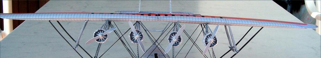
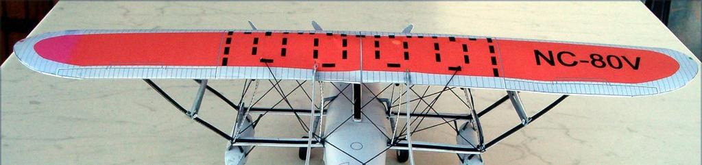
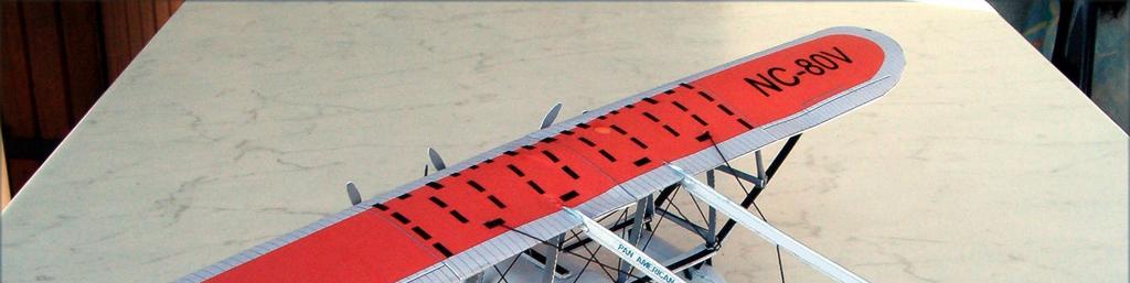
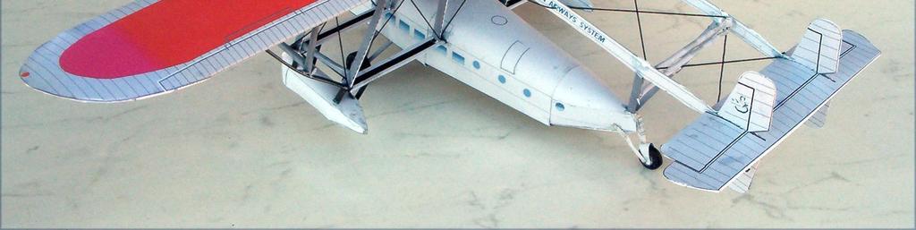
 The Sikorsky S-40 was an American amphibious flying boat built by Sikorsky in the early 1930s for Pan American World Airways.")

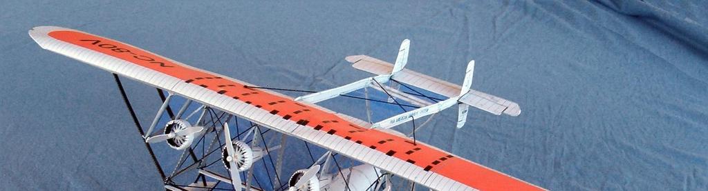
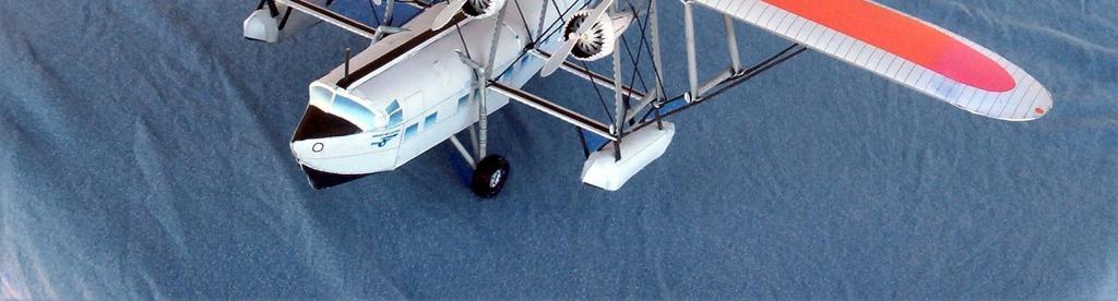
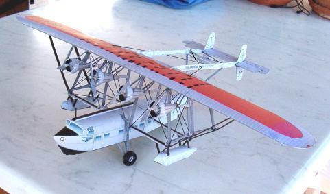
1 + Bob's Card Models and [Resources] Sikorsky S-40 (1:72) The Sikorsky S-40 was an American amphibious flying boat built by Sikorsky in the early 1930s for Pan American World Airways. It was the largest commercial airliner of its time. A total of three aircraft were built by the Vought-Sikorsky Aircraft Division of the United Aircraft Corporation in Stratford, Connecticut. All three were retired from service during World War II. The first passenger carrying service was on the November 19, 1931 and was piloted by Charles Lindbergh from Miami, Florida to the Panama Canal Zone. The S-40 was the first of many aircraft known as Flying Clipper and Pan Am Clipper. The S-40 was nicknamed the "Flying Forest" for its maze of support struts. Specifications General characteristics Crew: four Capacity: 40 passengers Length: 76 ft 8 in (23.37 m) Wingspan: 114 ft 0 in (34.76 m) Height: 23 ft 10 in (7.27 m) Wing area: 1,875 ft² (174.3 m²) Empty: 24,748 lb (11,249 kg) Loaded: 34,000 lb (15,455 kg) Maximum takeoff: lb ( kg) Powerplant: 4x Pratt & Whitney R-1690 radial engines, 575 hp (429 kw) each Performance Maximum speed: 135 mph (217 km/h) Range: 875 miles (1,408 km) Service ceiling: 13,000 ft (3,963 m) Rate of climb: ft/min ( m/min) 1
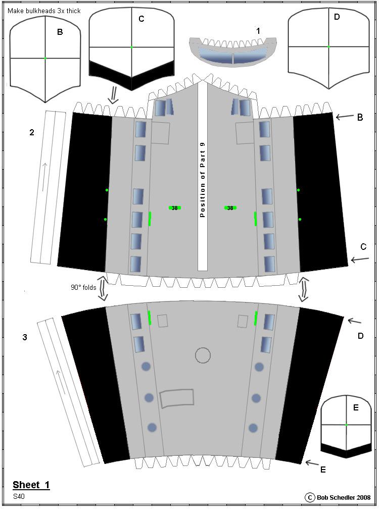
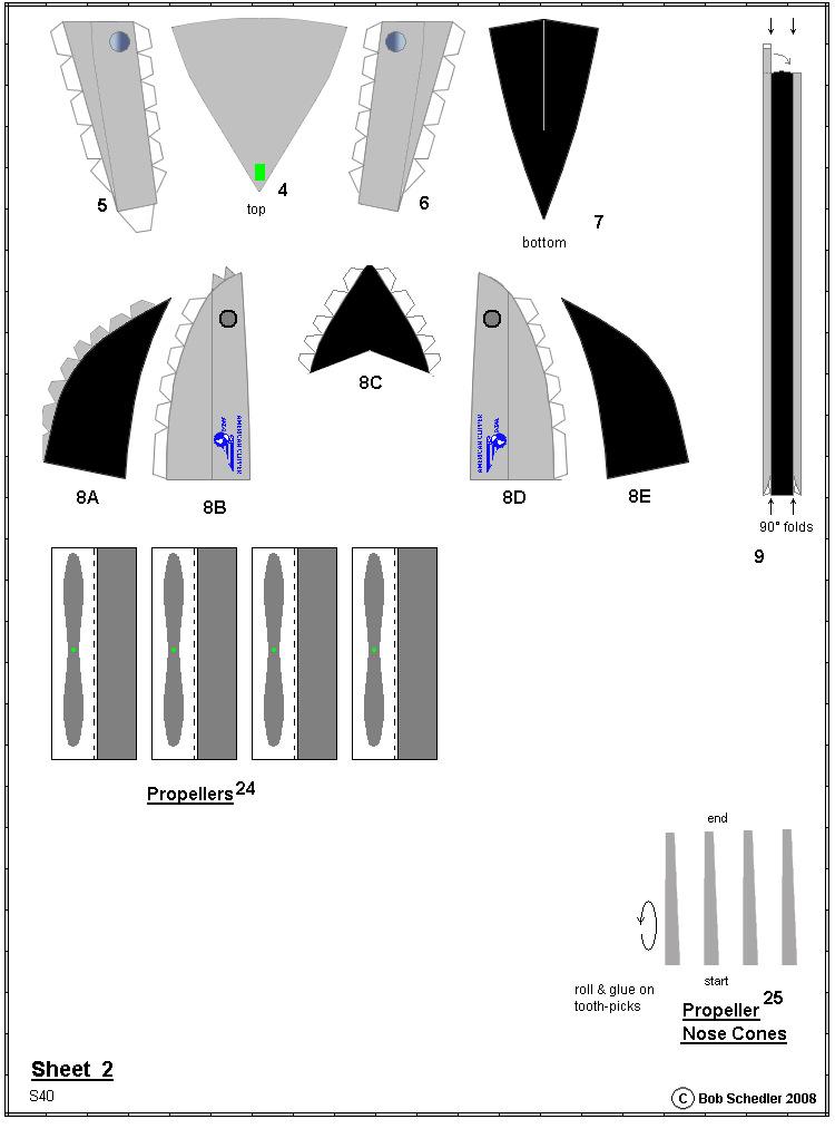
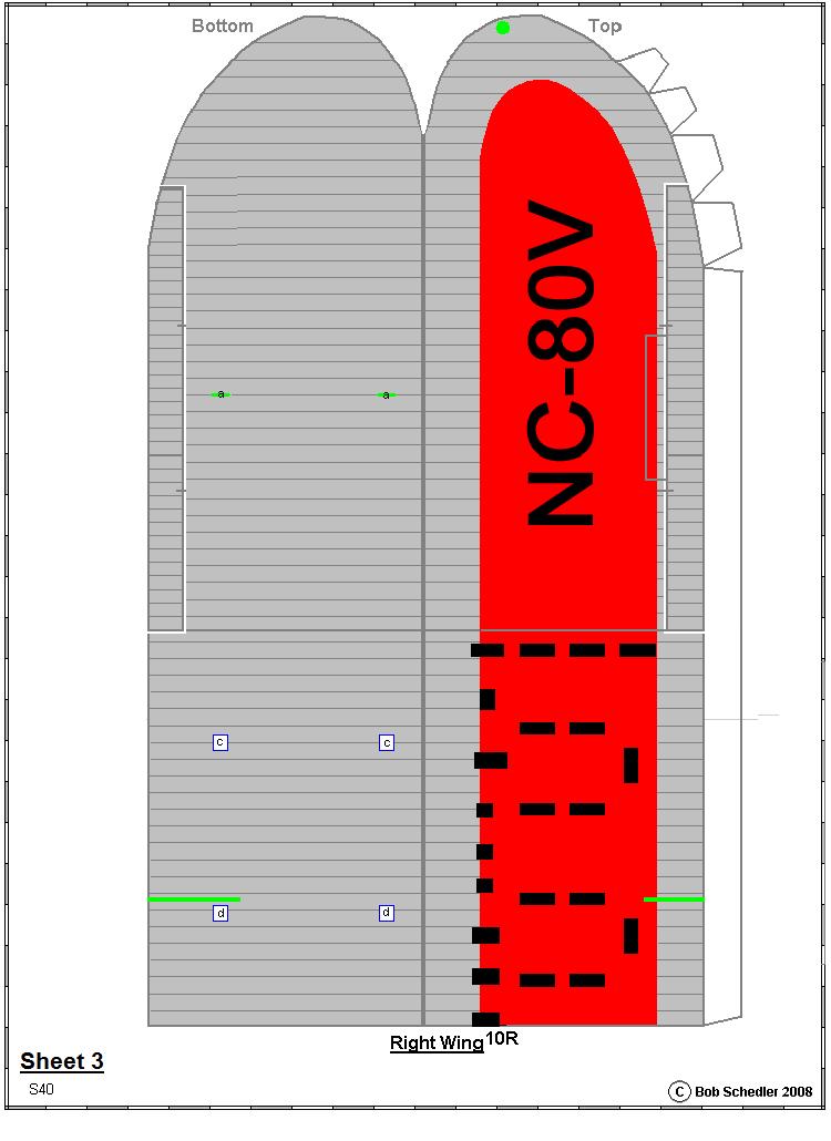
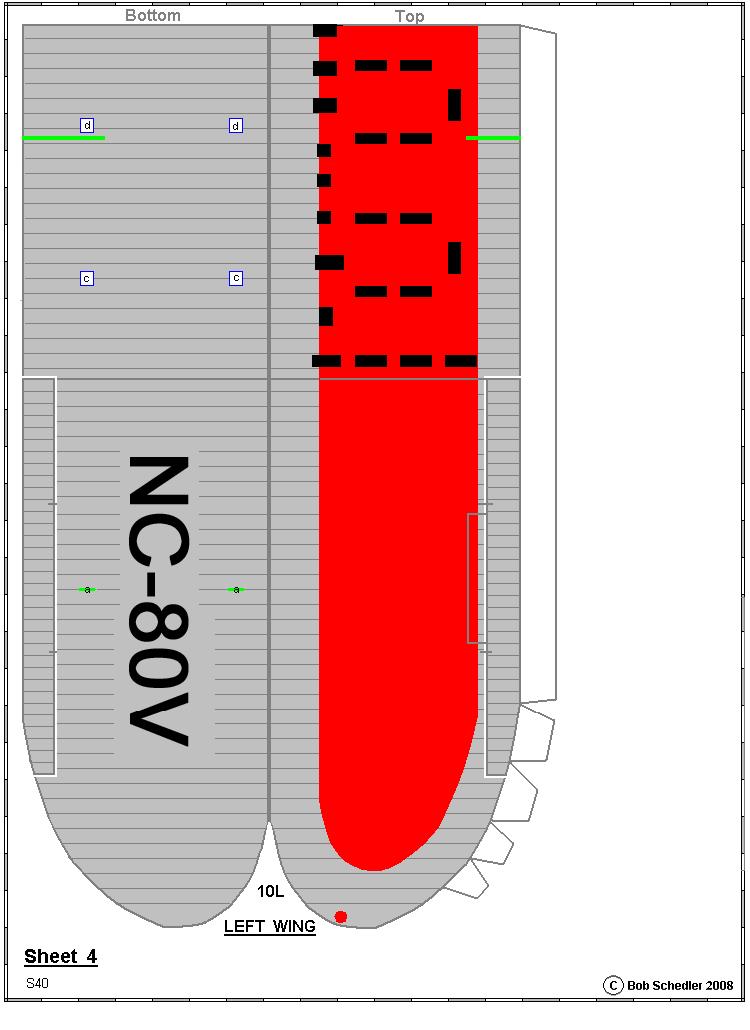
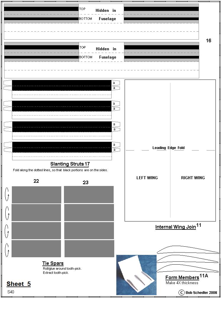
2 Wing loading: 18 lb/ft² (89 kg/m²) Power/Mass: 0.07 hp/lb (0.11 kw/kg) Building Instructions Print all sheets on between 160 and 230g card, except Instructions and Sheets 10 and 11 which should be printed on 80-90g Paper. Always carefully fit parts together before gluing, and make minor adjustments if necessary. Bright Green areas must be cut out, BUT only after gluing any folds. The Instructions will tell you when! Although the model is relatively small, bulkheads have also been used to keep the correct cross-sectional form of the fuselage. Thanks, for providing the excellent 3-D views, to : "l'encyclopédie illustrée de l'aviation" No. 127, and to for their free solid model plans. NOTE: When gluing on wings, tailplane and part 5A, make sure that they are exactly in line with the cockpit. Use elastic bands until the glue is dry. Fuselage 1. Cut out 3, bend the 2 sides (hull) to give the correct cross-section, round the form and especially the hull, glue on the long tab (which has been bent longitudinally to a V-form), and when dry, close/glue the form. 2. Insert bulkhead E (with centre pierced) through the front of 3 (side with black area facing to the rear), all the way through until flush with the rear, snipping off bits of E to a accommodate if necessary, and tack/glue. 3. In part 3, cut out the 2 slits above the foremost windows, and insert a waste piece of card as a stop when inserting bulkhead D Insert/glue-tack D (with centre pierced) in the front of 3. Push so far as it comes in contact with the card waste strips. When dry, remove the waste strips. 5. Cut out 2, bend the 2 sides (hull) to give the correct cross-section, round the form and especially the hull, glue on the long tab (which has been bent longitudinally to a V-form), and when dry, glue around the tabs of 3 as well as the long tab to close form. 6. At the rear end of 2, insert/glue-tack C (with centre pierced) in place so that it is flush (black portion pointing to the rear). 7. Insert bulkhead B (with centre pierced) through the front of 2 at about 5-10mm depth from the front of the part (do not force bulkhead, must sit loosely), tack/glue in place. 8. Glue together 2 and 3. If the tabs on 2 are a bit too long (pressing on bulkhead D), shorten. 9. Cut out 4-7. Round 4 to give the correct profile, add on 5 and 6 after bending their tabs 45, and end tab of 5 to Slight fold/round 7 and glue onto 4/5/6 (first one side, when glue dry, then the other side), and glue the unit onto the tabs of 3, noting the step in the hull. 11. Cut out 8A-E, bend tabs 45 excepting the grey-coloured tabs which are bent Glue 8B onto 8C. Glue 8A onto 8E, 8D to 8C, 8A to 8B so that the rear of 8A is flush with the rear of 8B. 13. Close/glue form. 14. Cut out windows 1, bend in the middle, bend tabs upwards except the side tabs (coloured grey). 15. Glue the tabs of 1 onto the inside of 8C. 16. Glue the unit 8A-E / 1 in place on the front of Cut out, fold, glue 9 on the top of the fuselage, starting from just above the cockpit windows. 18. Cut out green area on top and rear of 4. Wings 19. Cut out both wings 10, fold, bend tabs, glue each, then join Cut out the Wing Join 11, fold (round) the leading edge, then glue on the 3 Form Members 11A as shown in the photo, glue the top edge of each member, close form. 21. Glue one half of the Wing Join and insert in one of the wings; when dry, glue the other half and insert in the other wing. NOTE: the lower edge of the Form Members is curved - whilst the glue dries, hold in place gently with the fingers. 22. Cut out the 2 green slits in the wing (upper and lower sides) - ready for insertion later of the horizontal stabilisers 29. 2
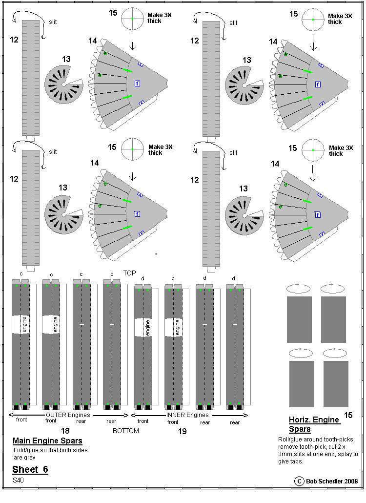
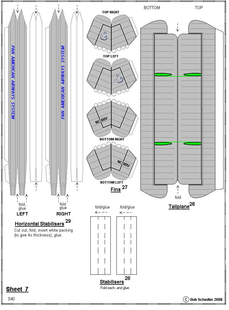
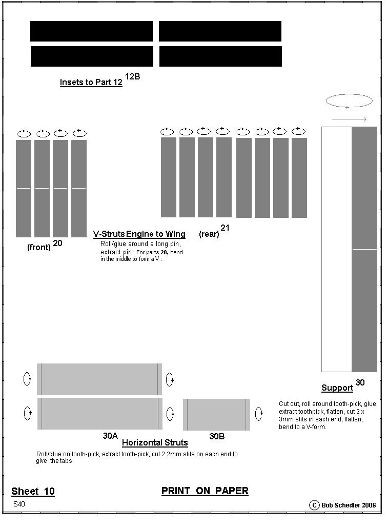
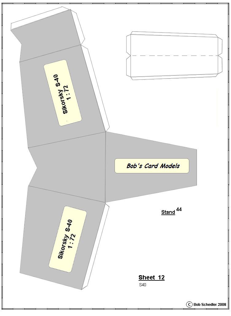
3 Engines (4) 23. Cut out 12, close form by gluing tab. Cut out a paper black strip 12B and glue on the inside of 12. Snip both sides along tiny lines (even better, cut out a tiny wedge in each case). 24. Cut out 13, form to a flat pyramid, glue tab. 25. Cut out 14, round and close/glue form. 26. Cut out 15, make 3x thick by gluing on waste card, pierce centre to accommodate a tooth-pick, then Insert in 14 as far as it will go, with glue on the rim. 27. Glue 13 in place, on Part 12: bend down the 'sniplets of one side, glue on the inside. When dry, insert from the rear of 13/14, bend down the front 'sniplets, glue. 29. Pierce the 2 green dots 'e' on each engine, enlarge with a tooth-pick to about 1-2mm diameter, cut out the 2 green slits. Struts (all green dots must be pierced before mounting, ready to receive the cotton cables ) 30. Cut out the 2 main horizontal struts 16, fold length-wise along the 3 dotted lines to give 4x thickness, glue - but only the rear of the grey strips, so that a space remains for later insertion of the tabs of the slanting struts. Press on a flat surface with a ruler, to ensure good adhesion, and a straight strut. 31. Insert the 2 horizontal struts in place, through the 2 green slits (cut out) above the 4 th and 7 th windows of the fuselage and glue in place. 32. Cut out the 4 slanting struts 17 and fold/glue as in 29. above; this time, all the inside surfaces can be glued. 33. Put a dab of glue on the tabs at one end of a slanting strut, and insert IN the end of a main horizontal strut; whilst the glue dries, bend up to an angle of ABOUT 45 and glue on position marked "a" on wing underside. Repeat with the 3 remaining slanting struts. 34. Cut, fold, bend all tabs outwards, and glue the 4 Main Engine Spars 18 (outer, front and rear), in 2 of them insert the engines (glue in the marked place on the spars with the 2 green dots 'e' UPPERMOST), and glue in blue rectangle position marked "c". 35. Likewise the 4 Main Engine Spars 19 (inner), and glue in blue rectangle position marked "d". 36. Cut out, roll the V- Struts for the engines 20, roll/glue around a long pin, extract pin. Bend in the middle to a V, and glue the 2 arms in place in the engine housing at positions "e" (pierce beforehand), and the V-bend at position "c". 37. The rear struts 21 are only half-length as otherwise they would be too long to roll around a pin. Cut them out, roll around a pin, glue, extract pin, flatten each end about 5mm, then glue in position on the engine housings at positions marked "f", and to the top of the rear vertical struts 18 and Cut out the 4 Tie Spars 23, roll around a tooth-pick and glue. Snip each (after flattening the tube a bit) end about 2mm to give 2 tabs at each end - bend these back 90, and glue in place joining the middle of 17 to the wing. Make sure the spars are parallel to the struts Cut out the 4 Tie Spars 22, roll around a tooth-pick and glue. Extract tooth-pick, flatten each end about 5mm. Glue 2 of the spars in position joining the extremities of the main horizontal struts 16, and the other 2 to join the base of the front and rear Tie Spars 23. Propellers 40. Cut out, fold, glue, cut out the propellers 24 and their respective Nose Cones 25. Glue the props each on a tooth-pick, glue on the Nose Cones. Insert in the engine after cutting the tooth-pick to an adequate length. (NOTE: Best to insert the propeller units during the last stage of construction, otherwise they will get in the way, and perhaps become damages). Tailplane 40. Cut out tailplane 26, fold main tab and the 2 halves, and cut out the green areas. Do not glue yet! 41. Cut out the 4 fins 27. Fold the 2 halves and the main tab, and fold UP the small tabs. Glue the main tab and close the form. Do not yet glue the tops of each fin together. 42. Insert the 4 fins in their positions in 26, and glue their small tabs to the inside of the tailplane. 43. Glue/close the 2 wing halves. 44. Through the top of one set of fins, insert the stabiliser 28, but it is not necessary to glue it in place. Close/glue the tops of each fin. 45. Repeat for the other set of fins. 46. Cut out the 2 horizontal stabilisers 29, fold, insert packing (or better: insert a thin barbecue stick in each), close/glue. 47. Glue onto horizontal stabiliser of tailplane in the 2 green slits previously cut out. Cut out support 30, roll/glue around long toothpick or rod of 2-3mm diameter, extract toothpick, flatten, cut 2 x 3mm long slits in each end, bend to a V-form, and glue in place (the V in the green cut-out slit at the rear of 4, and the 2 other ends on the underside of each part 29, so that the stabilisers 29 are parallel to the middle- 3
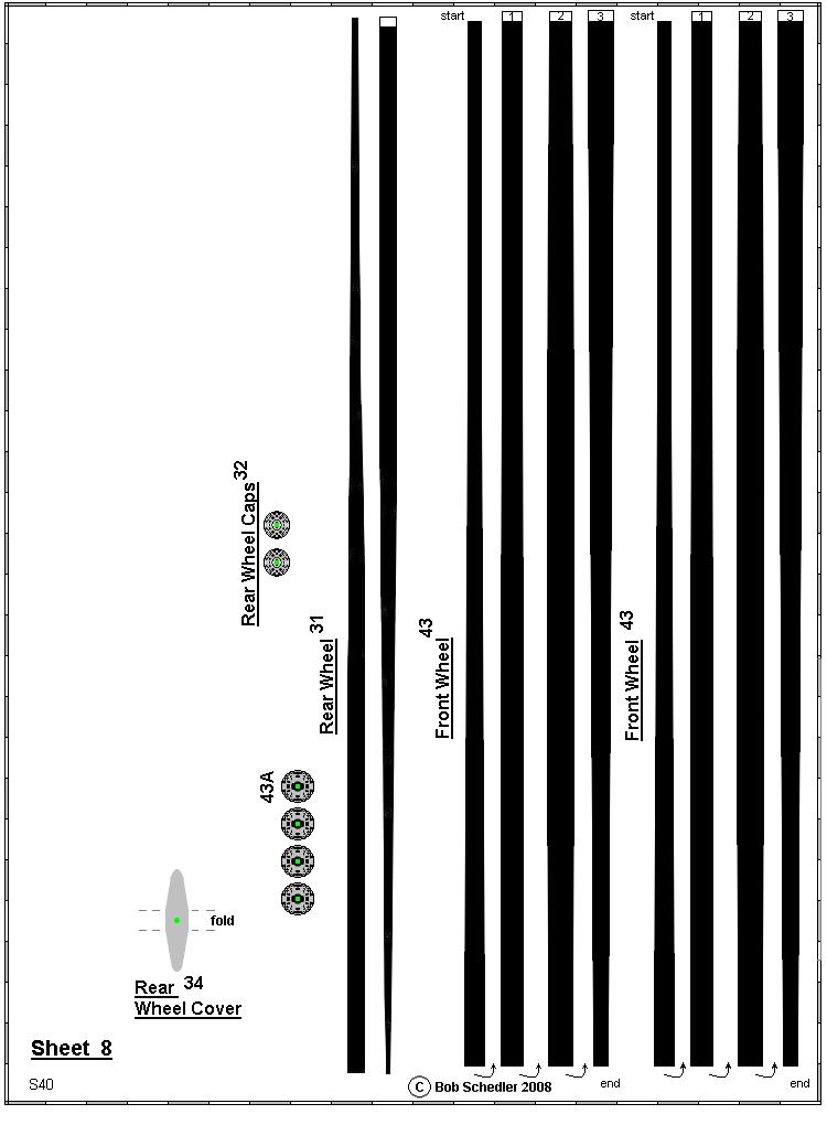
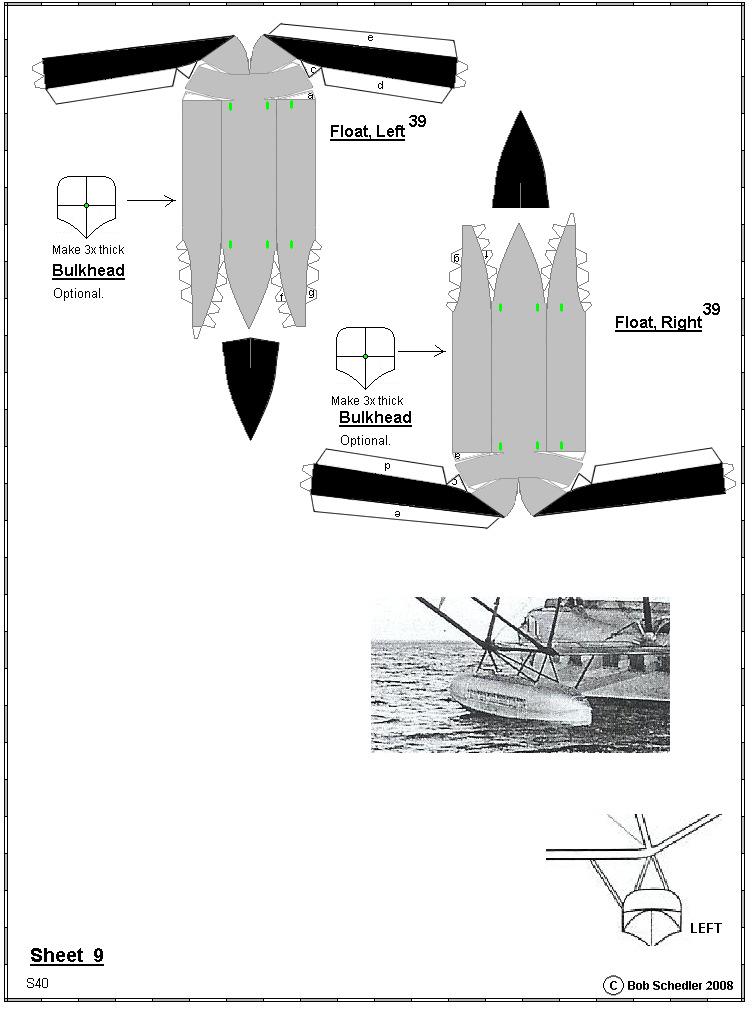
4 line of the fuselage). Glue the tabs of horizontal stabiliser 30A to join the 2 V-ends of part 30, and 30B half-way down, inside the V-strut. NOTE: There are actually 2 parts 30A - place one exactly above the other, with about 3-5mm space between the Glue the front ends of the horizontal stabilisers 29 to the cut-out positions of the main wing. Undercarriage 49. Rear Wheels: cut out and roll/glue tyre 31. Pierce centre. Glue a wheel cap 32 on each side. Pierce centre. 50. Cut out and roll/glue vertical strut 33 so that about 5mm of the tooth-pick point protrudes. Cut the other end so that 1mm protrudes. 51. Cut out rear wheel cover 34, pierce centre, fold, insert in pointed end of 33 and insert/glue pointed end in the rim of the wheel in which a small hole has been drilled/cut. 52. Glue the ends of 34 to the centre of the wheel caps. Glue the other end of the toothpick on the rear of the fuselage (part 7). 53. Add left and right of the fuselage, parts 35. Glue in position on the fuselage and on the wheel covers Main undercarriage: form a V with 2 toothpicks, and glue the join (see Sheet 11 diagram). When glue is hard, add 2 sleeves 36 to the Wheel Main Struts 37. Repeat for the other side. Insert each in the positions marked (green, cut out) and glue in place. The necessary angles are shown on Sheet Cut out the 2 (left and right) vertical supports 38 to the undercarriage, glue around a toothpick, and when dry, bend ca by cracking the tooth pick at the white line. Glue in place - top end inside the slit marked "38" on top of the fuselage, bottom ends on the inside of the Wheel covers, joining part Add the wheels 43 and glue these in place with a dob of glue. Add the wheel caps 43A. Floats 57. Cut out the 2 floats 39. Bend to form. Slightly bend all tabs, then glue tabs in the following order - a, b, c, d, e. Insert the 3x thickness bulkhead to preserve profile. Cut out all green slits (for the spars). Option: omit the Bulkhead if no difficulty is encountered in forming the correct cross-section of the floats. 58. Add the struts: Cut out 2 of the struts 40 and roll/glue each around a tooth-pick. Remove toothpick, flatten. Bend in the middle to a V-form, insert/glue in position (inverted V) on top of the float in the positions marked on the top of the float at the front, and at the rear. Repeat for the other float. Add a dob of glue on the top of the inverted V, and hold in position until dry. Add the inclined struts 41, insert the tabbed end into the float, and when dry, put a dob of glue on the other end and glue to the underside end of the main struts 16. Aerial 59. Add aerial 42 just above cockpit. 60. Assemble the Stand 44 if desired. Rigging Some of the rigging (cables) has been attached and purists may say that some or other cable is missing.i have absolutely no objection to additional rigging, but I added only the main ones. I use cotton-coated rubber to give an elasticity. Use under minimal tension, just enough to prevent sag. ---ooooooo--- 4


5 5
6 6
7 7
8
9
10
11
12
13
14
15
16
17
18
19
Bob's Card Models and [Resources]
![Bob's Card Models and [Resources]](/thumbs/78/77827598.jpg "Bob's Card Models and [Resources]") Bob's Card Models www.bobscardmodels.altervista.org and www.zealot.com [Resources] Mitsubishi A5M4 1:30 The Mitsubishi A6M Zero was a lightweight fighter aircraft operated by the Imperial Japanese Navy
Bob's Card Models www.bobscardmodels.altervista.org and www.zealot.com [Resources] Mitsubishi A5M4 1:30 The Mitsubishi A6M Zero was a lightweight fighter aircraft operated by the Imperial Japanese Navy
Bob's Card Models and [Resources]
![Bob's Card Models and [Resources]](/thumbs/90/103692932.jpg "Bob's Card Models and [Resources]") Bob's Card Models www.bobscardmodels.altervista.org and www.zealot.com [Resources] Robin DR400-140B Major 1:25 The Robin sport monoplane, conceived by Pierre Robin and Jean Délémontez. The Robin DR400
Bob's Card Models www.bobscardmodels.altervista.org and www.zealot.com [Resources] Robin DR400-140B Major 1:25 The Robin sport monoplane, conceived by Pierre Robin and Jean Délémontez. The Robin DR400
Bob's Card Models
 Bob's Card Models www.bobscardmodels.com 1 Airbus A300-600ST, "Beluga" The Airbus A300-600ST (Super Transporter) or Beluga is a version of the standard A300-600 wide-body airliner modified to carry aircraft
Bob's Card Models and [Resources]
![Bob's Card Models and [Resources]](/thumbs/74/69776662.jpg "Bob's Card Models and [Resources]") Bob's Card Models http://www.bobscardmodels.altervista.org/ and www.zealot.com [Resources] Savoia-Marchetti S.55 1:72 The Savoia-Marchetti S.55 was a double-hulled flying boat produced in Italy beginning
Bob's Card Models http://www.bobscardmodels.altervista.org/ and www.zealot.com [Resources] Savoia-Marchetti S.55 1:72 The Savoia-Marchetti S.55 was a double-hulled flying boat produced in Italy beginning
Bob's Card Models and [Resources]
![Bob's Card Models and [Resources]](/thumbs/88/114672887.jpg "Bob's Card Models and [Resources]") Bob's Card Models www.bobscardmodels.altervista.org and www.zealot.com [Resources] DC-3 / C-47 According to www.airliners.net, EC-AHA is a DC3 which had been abandoned on a glacier in Iceland in 1950,
Bob's Card Models www.bobscardmodels.altervista.org and www.zealot.com [Resources] DC-3 / C-47 According to www.airliners.net, EC-AHA is a DC3 which had been abandoned on a glacier in Iceland in 1950,
Your kit contains the following items. Additional Items You May Need. Pre- cut parts Propeller rigging and rubber Sandpaper Covering sheet
 Your kit contains the following items Pre- cut parts Propeller rigging and rubber Sandpaper Covering sheet The SkyFox offers great glide performance in a rubber powered plane due to its built up wing.
Stevenson Projects Building the Hull Top Deck and Bulkheads
 Stevenson Projects Building the Hull 1. Print out both piece sheets. 2. Cut out one keel piece and glue it to a piece of balsa wood or dense cardboard. Cut out the second keel piece and glue it to the
Dornier Do R 4 Super-Wal
 Dornier Do R 4 Super-Wal Model Aviation Laddie Mikulasko s Dornier Do R 4 Super-Wal Build the multiengine, record-setting seaplane. Article, plans, instructions, and photos by Laddie Mikulasko. Complete
aero naut Electric Model Aeroplane Quido Order-No. 1303/00
 aero naut Electric Model Aeroplane Quido Order-No. 1303/00 Quido is a small model that accompanies you wherever you go. The prefabricated parts are mostly balsa and just need to be assembled according
Cleopatra British Obelisk Transport Barge. Kartonbau.de Exclusive Edition
 Cleopatra 188 British Obelisk Transport Barge Kartonbau.de Exclusive Edition Copyright 2006 Oliver Weiss / The Walden Font Co. P. O. Box 81, Winchester, MA 01890 www.waldenfont.com Historical Notes The
Build This World Record Fuselage Model
 Build This World Record Fuselage Model Here You Have Complete Instructions and Plans to Build a Plane of Sure-fire Performance that Established a World Record at the 1932 National Airplane Model Competition
8-GUN CORVETTE ASSEMBLY INSTRUCTIONS
 8-GUN CORVETTE ASSEMBLY INSTRUCTIONS THE HULL STEP 1 Fasten the Deck to the Hull. Find the hull. This is a large, pink, ship-shaped piece of insulating foam board. This will form the base of your model
Samurai Armor Set: Step by Step
 Samurai Armor Set: Step by Step Pack 3 Stages 9-12 1 Contents Stage 9 Pages 29-31 The cuirass side and tassets Stage 10 Pages 32-37 The shoulder plate and tassets Stage 11 Pages 39-41 The shoulder plate
Bladerider X8 Assembly Help Notes
 2.1 Remove All Parts & Have Some Tools Handy Remove all items from the box and identify each part as per the packing sheet and check that nothing is missing. If there is something missing, please email
Constitution Instructions
 Constitution Instructions This kit will build a 1:48 scale hull for the USS Constitution frigate. The kit contains the following parts. 1/8 deck with laser etched deck lines 1/8 railing Ribs Center keel
PAY N PAK, 1/12 th Scale, Limited Sport Hydro P Sport Hydro
 1980 82 PAY N PAK, 1/12 th Scale, Limited Sport Hydro P Sport Hydro Introduction: The 1980 turbine Pay N Pak is a good subject for a model race boat. It has a low profile, mild pickle-fork setback, long
Model Aero Sportster Indroduction
 1 Model Aero Sportster Indroduction We are excited to introduce the Model Aero Sportster! Inspired by classic designs of the past, the Sportster is a relaxing slow flyer, equally at home indoors or outside
1/10 th Scale 1956 Ted Jones Classic Hydroplane
 1/10 th Scale 1956 Ted Jones Classic Hydroplane Preparation These plans show outside sheeting of 3/32 balsa laminated with 1/64 birch ply. This makes a light and strong skin for this boat. Optionally you
Samurai Armor Set: Step by Step
 Samurai Armor Set: Step by Step Pack 6 Stages -5 Contents Stage Pages 7-76 The tasset plates and shoulder pad Stage Pages 77-8 The tassets, helmet and helmet lining Stage Pages 8-86 The tasset plates and
Pre-Paint>Fuselage>Empennage>Fit vertical tail fin. Objectives of this task: Materials and equipment required: Fit the spar extender
 Pre-Paint>Fuselage>Empennage>Fit vertical tail fin Objectives of this task: To fit the vertical tail fin to the fuselage, including fitting the static probe, static tube, optional strobe light wiring and
The author's TD Coupe, used as a towplane, and the Airhopper. The gas model is equipped with an automatic towline release.
 THE AIRHOPPER BY STANLEY ORZECK PLANS BY PAUL PLECAN An eight-foot sailplane either towed by a gas model or launched by hand tow. The author's TD Coupe, used as a towplane, and the Airhopper. The gas model
Annex E(M) - Final inspection checklist - monowheel
 - Final inspection checklist - monowheel") Annex E(M) - Final inspection checklist - monowheel A/C Reg... Owner...Kit S/N...Date... (U.K. Only) L.A.A No...Inspector...Insp. No... Note: This check list only covers specific items for inspection of
Annex E(M) - Final inspection checklist - monowheel A/C Reg... Owner...Kit S/N...Date... (U.K. Only) L.A.A No...Inspector...Insp. No... Note: This check list only covers specific items for inspection of
1939 STOUT TROPHY WINNER
 1939 STOUT TROPHY WINNER This model's 36-minute flight won the Stout Trophy and qualified the builder as captain of the American Moffett team. Bob Toft. Has won a second in gas, first in rubber at Nationals.
Darling Downs Soaring Club Inc
 Darling Downs Soaring Club Inc Rigging and De-Rigging Instructions LS7 XOW Overview Page 2 Rigging page 3 De-Rigging page 19 Overview It is the pilot s responsibility to make sure that the trailer is fully
Bottle Rocket Launcher P4-2000
 WWW.ARBORSCI.COM Bottle Rocket Launcher P4-2000 BACKGROUND: The Bottle Rocket Launcher allows for the exploration of launching rockets using commonly available materials such as plastic soda bottles and
Model Aero AT-6 Texan Introduction
 1 Model Aero AT-6 Texan Introduction We are excited to introduce the Model Aero AT-6 Texan! Originally used as an advanced trainer by the U.S. Armed Forces, the AT-6 is a relaxing slow flyer, equally at
Assembly instructions nortik scubi 2 Recreational kayak
 Assembly instructions nortik scubi 2 Recreational kayak QR-Code assembly video: Assembly instructions nortik scubi 2 Dear Customer, You have purchased a nortik scubi 2, an innovative hybrid kayak for recreational
Parkzone Vapor Repair tutorials
 Propeller replacement The propeller is held on by the threaded shaft. You will need to grip the shaft/cog with your fingers or some pliers and rotate the propeller anticlockwise when viewed from the front.
Foam Plate Glider: Sonic Silhouette
 Designed by: Ritchie Kinmont Project #40 Page 1/25 Foam Plate Glider: Sonic Silhouette About this project: The Foam Plate Glider Sonic Silhouette is the first in a series of flying glider projects made
Horizontal Fuselage. Top Vertical Fuselage 1. Lay out the Top Vertical Fuse Front(1), Top Vertical Fuse Back(2), and Vertical Stabilizer(3).
, Top Vertical Fuse Back(2), and Vertical Stabilizer(3).") Rumbuilder 71 B-17 Congrats on your Rumbuilder B-17! We re glad you chose to fly with us! If you have any problems, or missing/broken kit pieces, please contact us. We d be happy to replace any damaged
Rumbuilder 71 B-17 Congrats on your Rumbuilder B-17! We re glad you chose to fly with us! If you have any problems, or missing/broken kit pieces, please contact us. We d be happy to replace any damaged
THE AMERICAN BARN DOOR KITE
 THE AMERICAN BARN DOOR KITE Oregon Kitemaker s Retreat January 2007 Rod Beamguard 4104 NW 112 th Way Vancouver, WA 98685-3578 (360) 574-8050 home (360) 750-9833 office kytfevr@wa-net.com PLANFORM BARN
aero naut Order No. 3009/00
 aero naut Order No. 3009/00 Introduction: The model should be assembled following the sequence of the stages of construction described in these instructions. The laser-cut components are individually numbered.
PART 1 Rocket Assembly
 PART 1 Rocket Assembly Please understand that there are many ways for you to do this. Here is one way Bottle Rocket Lab Activity Student Edition OBJECTIVE: The Student will design, construct, assemble,
Boat Boat Loader Fitting Instructions
 Aerodynamic & Heavy Duty Roof Rack Systems Australian Made - Australian Owned www.rhinorack.com Boat Boat Loader Fitting Instructions CONTROLLED Balance point 3 Front eye nuts position 3 Transom eye nut
We hope you ll enjoy the Drifter as much as we have! Scott DeTray Model Aero Specifications:
 We are excited to bring you the Drifter RC airboat. You re probably thinking it doesn t fly so what is Model Aero thinking??? We have always liked RC vehicles of all types and have had a fondness for airboats
Learning to Fly: The Wright Brothers Adventure EG GRC 39
 Learning to Fly: The Wright Brothers Adventure EG 2002 12 007 GRC 39 The Wright Brothers 1900 aircraft was flown repeatedly at Kitty Hawk, North Carolina, during the fall of 1900, mostly as a kite but
Soling Building Tips II
 Soling Building Tips II Prepared: Arthur Deane Jan 20, 2002 adeane@ic.net Introduction The following are some lessons learned and experience gained in building a Soling kit. The plan developed is based
Blazer Marine, Whiplash Sport 40
 Blazer Marine, Whiplash Sport 40 Thank you for choosing to build the Whiplash 40. We have spent over 12 years perfecting this design, and finally we are making it available to the world. We are excited
Troyer s Gourd Rack 8 unit F R H O P
 B E A D I M-N L Vertical Parts F R H O P Horizontal Parts C G J Updated 11/16 Parts List A: Top of Pole B: Bottom of Pole C: 48 Ground Stake D: Top Perch rods 48 long E: Hub F: Rope Winder w/ attached
INSTRUCTIONS FOR GLUING ON THE BUMPER FOR PORT TOWNSEND WATERCRAFT S NESTING DINGIES. (Or requires a 1 surface to adhere to.)
") INSTRUCTIONS FOR GLUING ON THE BUMPER FOR PORT TOWNSEND WATERCRAFT S NESTING DINGIES. (Or requires a 1 surface to adhere to.) The PT 11 bumper is made from a high quality, non marking EPDM rubber. This
INSTRUCTIONS FOR GLUING ON THE BUMPER FOR PORT TOWNSEND WATERCRAFT S NESTING DINGIES. (Or requires a 1 surface to adhere to.) The PT 11 bumper is made from a high quality, non marking EPDM rubber. This
BOYLE S / CHARLES LAW APPARATUS - 1m long
 BOYLE S / CHARLES LAW APPARATUS - 1m long Cat: MF0340-101 (combination Boyle s and Charles without mercury) DESCRIPTION: The IEC Boyle's & Charles Law apparatus is a high quality instrument designed to
1 General. 1.1 Introduction
 1 General 1.1 Introduction The contents of this book will focus on the anatomy of the aeroplane and the various systems that enable it to operate both on the ground and in the air. Flight controls Landing
PUT TING SCIENCE TO FLIGHT T E A C H E R S G U I D E
 PUT TING SCIENCE TO FLIGHT T E A C H E R S G U I D E Rocco Fer rario Teacher, American Canyon Middle School Napa, CA 55747 TECH TIPS Building Tips for the Raven Broken wings are a bummer. Unless the dihedral
TOPLESS OWNER S MANUAL
 LA MOUETTE GLIDERS TOPLESS OWNER S MANUAL CONTENTS 1. Description of design--------------------------------------------- 2 2. Specifications ----------------------------------------------------- 2 3. Operating
STOL CH rd Edition Drawings, dated April 16, 2012 Summary of changes from Edition 2 Revision 1 to Edition 3.
 STOL CH 750 3 rd Edition Drawings, dated April 16, 2012 Summary of changes from Edition 2 Revision 1 to Edition 3. Page Date Drawing Title 75-G-0 04/12 Three View Drawing 1. Edition 3 75-G-1 04/12 Drawings
!""#$%!!!!!!!!!!!!!!! "#$%!&'()*!$%!*(%+!,-!.-'/!()/!.'$*%!%,0($1#,!()/!%2--,#3!!4//!(!%2(''!(2-5),!-.!5&! *'*6(,-0!.-0!'-)1!'*6*'!.'$1#,%3!!!!!!!!
*!$%!*(%+!,-!.-'/!()/!.'$*%!%,0($1#,!()/!%2--,#3!!4//!(!%2(''!(2-5),!-.!5&! *'*6(,-0!.-0!'-)1!'*6*'!.'$1#,%3!!!!!!!!") ""#$% "#$%&'()*$%*(%+,-.-'/()/.'$*%%,0($1#,()/%2--,#34//(%2(''(2-5),-.5& *'*6(,-0.-0'-)1'*6*'.'$1#,%3 70$*),,#*,*2&'(,*8$,#,#*9:;
""#$% "#$%&'()*$%*(%+,-.-'/()/.'$*%%,0($1#,()/%2--,#34//(%2(''(2-5),-.5& *'*6(,-0.-0'-)1'*6*'.'$1#,%3 70$*),,#*,*2&'(,*8$,#,#*9:;
SAFETY WARNING. WARNING.
 EXPERIMENT MANUAL 1ST EDITION 2014 2014 THAMES & KOSMOS, LLC, PROVIDENCE, RI, USA THAMES & KOSMOS IS A REGISTERED TRADEMARK OF THAMES & KOSMOS, LLC. PROTECTED BY LAW. ALL RIGHTS RESERVED. WE RESERVE THE
Building a Rocket (Advanced) Before you build a rocket try the bottle on the launcher to test if it holds pressure and fits correctly.
 Before you build a rocket try the bottle on the launcher to test if it holds pressure and fits correctly.") You Will Need 3X 2ltr Bottles 1X Paper lip 1X Glue/Double Sided Tape 1X ardboard 1X Bin Liner 1X Roll of Fishing Line or Thin s Sheets of Paper Side A of Fin 1X Hot Glue Gun 1X Pair of Scissors 1X Fine
You Will Need 3X 2ltr Bottles 1X Paper lip 1X Glue/Double Sided Tape 1X ardboard 1X Bin Liner 1X Roll of Fishing Line or Thin s Sheets of Paper Side A of Fin 1X Hot Glue Gun 1X Pair of Scissors 1X Fine
Fauvel AV36 tailless glider Scale 1:16
 Fauvel AV36 tailless glider Scale 1:16 F11 (Page 1) Original colours: RAL 2009 RAL 6017 (Page 2) F9 F10 RAL 3020 RAL 7047 F4 F5 F8 F1 Abbreviations used for numbering parts: A = wings ( ailes ) D = empennage
Assembly Instruction - Triton Vuoksa 2 advanced Touring kayak
 Assembly Instruction - Triton Vuoksa 2 advanced Touring kayak QR-Code assembly video: You can find many assembling videos to our boats on our YouTube channel: https://www.youtube.com/c/faltbootde Assembly
18. Tailplane torque-tube
 18. Tailplane torque-tube Step 1 Fu se lage rear bulkhead Remove the three part templates of the rear bulkhead: an A4 size sheet from Annex A (page 5) and two A3 size sheets from Annex F of the manual,
Introduction. Have Fun Pat Morgan patsplanes.com. The cool paper airplane site!
 Folded Designs Introduction Since at least 1909 paper planes have been folded and flown and become addictive to the true fan. I have been folding paper airplanes for over 45 years and designing them for
ASSEMBLING INSTRUCTION - TRITON LADOGA 2 ADVANCED
 ASSEMBLING INSTRUCTION - TRITON LADOGA 2 ADVANCED Touring and sea kayak Assembly video: Assembling Instruction - Triton Ladoga 2 advanced Dear Customer, At first: please do not be alarmed by the extent
Southern Eagles Soaring
 Southern Eagles Soaring N56LS Standard Cirrus Disassembly / Assembly Procedure. Version 2, 2017 You landed out so what now? First, hopefully you made arrangements with someone who has a hitch on their
Lesson Plan: Bernoulli s Lift
 Lesson Plan: Bernoulli s Lift Grade Level: 5-6 Subject Area: Time Required: Science Preparation: 30 minutes Activity: 3 40-minute classes National Standards Correlation: Science (grades 5-8) Physical Science
WHITE ENSIGN MODELS. 7. Etched parts 20 are the netted sections of railing that fit to the edges of the mid gun deck extensions, kit parts D25.
 WHITE ENSIGN MODELS RN Littorio-Class Battleships Photoetched Metal details to fit the Trumpeter kits in 1/00 Scale Instructions for working with Photoetched Metal 1. Do not remove the etched parts from
Instruction Manual. Features. Specification: Length: 730mm Width: 500mm Height: 1000mm Sail Area: 0.15m 2. Weight: 692g (w/o battery & receiver)
") AN UNBELIEVABLE SPEED MACHINE Instruction Manual Features Specification: Length: 730mm Width: 500mm Height: 1000mm Sail Area: 0.15m 2 Weight: 692g (w/o battery & receiver) Thank you for purchasing your
AN UNBELIEVABLE SPEED MACHINE Instruction Manual Features Specification: Length: 730mm Width: 500mm Height: 1000mm Sail Area: 0.15m 2 Weight: 692g (w/o battery & receiver) Thank you for purchasing your
A Table Top Wind Tunnel You Can Build
 A Table Top Wind Tunnel You Can Build Basic principles of aerodynamics can be studied in the classroom with this simple, inexpensive wind tunnel. All you need to build it is some cardboard boxes, glue,
Protected Microducts, Overview and Current Trends
 Draka Comteq Netherlands / Comparison of Microduct Types for optical cables installation Protected Microducts, Overview and Current Trends W. Griffioen 1, W. Greven 2 1 Draka Comteq Cable Solutions, Amsterdam,
MANDATORY BULLETIN No.: SAFETY RELATED. EV a SR. Appendix 1 Bulletin Flow Chart
 Appendix 1 Bulletin Flow Chart Form No.: QS-406/F-03A Issue: Date of Issue: Page: 2 APPENDIX 2 Inspection of Nicopress Pressing Tooling: Vernier calliper or Nicopress check gauge Felt-tip pen to mark clamps
Sails. Sails: extract from 'Super-detailing the Cutter Sherbourne' page 1 George Bandurek
 Sails There are many arguments for adding or omitting the sails on a model ship. There is no right answer and I decided to have a combination of set and furled sails on my model of HM cutter Sherbourne
BUILDING INSTRUCTION Glider TASER unplugged. Taser unplugged Building instruction September
 Wingspan [mm]: 2000 Takeoff weight [g]: From 400 Airfoil: AG 455ct-02f AG47ct-02f by Mark Drela BUILDING INSTRUCTION Glider TASER unplugged www.pcm.at 1 CONTENTS DATA 1. Kit contents 2. What else do you
Pitts Model 12 Wing Leading edge Installation
 Pitts Model 12 Wing Leading edge Installation This procedure is used to install molded plywood leading edges included in the Pitts Model 12 kit. Nine (9) molded leading edge section are require per aircraft;
Instructions for Fun Foam Critter 4/25/2007 BP Hobbies LLC 140 Ethel Road W Suite J Piscataway NJ,
 Instructions for Fun Foam Critter 4/25/2007 BP Hobbies LLC 140 Ethel Road W Suite J Piscataway NJ, 08854 http://www.bphobbies.com Specifications: Wing Span: 20" Length: 20" Flying Weight: 5.5-7.0 oz Controls:
AVA Building Instructions
 Suggested Assembly Sequence: AVA Building Instructions 1. Insert fittings in rudder and trial fit rudder on boom 2. Attach stab to v-mount and position ahead of rudder ¼, sanding the v-mount as needed.
BASIC AIRCRAFT STRUCTURES
 Slide 1 BASIC AIRCRAFT STRUCTURES The basic aircraft structure serves multiple purposes. Such as aircraft aerodynamics; which indicates how smooth the aircraft flies thru the air (The Skelton of the aircraft
RATLINER Assembly Instructions.
 Model Shipways Inc. www.modelexpo-online.com RATLINER Assembly Instructions. Patent Pending 1. Remove center stands and braces from the main rigging frame. 2. The Stands and Braces should press release
Shrouds, dead-eyes and ratlines
 Shrouds, dead-eyes and ratlines On a real vessel the shrouds would be put up before the running rigging and many modellers follow this sequence. On Sherbourne I attached the stays and the running rigging
Wing assemblyfinal Master 4/29/04 11:20 PM Page 1. Issued January 1, Sabre Aircraft. Assembly Manual. Sabre 16ss Wing
 Wing assemblyfinal Master 4/29/04 11:20 PM Page 1 Issued January 1, 2002 Sabre Aircraft Assembly Manual Sabre 16ss Wing Wing assemblyfinal Master 4/29/04 11:20 PM Page 2 1. 2. 1. Unzip the cover and remove
Butler Parachute Systems, Inc
 Butler Parachute Systems, Inc A division of Butler Parachute Systems Group, Inc. TT-600 GEN 1 & 2 TETHERED TANDEM BUNDLE DELIVERY SYSTEM ASSEMBLY MANUAL 1 JUN 2010 INTRODUCTION This manual contains all
NAVIGATOR PROP BUILDING INSTRUCTIONS & PHOTOS
 NAVIGATOR PROP BUILDING INSTRUCTIONS & PHOTOS Science under the ice Ice sheet At regional competitions the ice is simulated by 8 ft x 4 ft ½-inch foam sheeting (Home Depot part #703990 [in store only],
SEADUCER BOATS GAS SPORT HYDRO
 SEADUCER BOATS GAS SPORT HYDRO COME VISIT US ON THE WEB AT WWW.SEADUCERBOATS.COM 2 - Pkg. Of 440 push rod ends 2 - Pkg. of solder-on rod ends 2 -water outlet fitting 1-1/4" prop nut 1 -.250" x 30" flex
Related Careers: Aircraft Instrument Repairer Aircraft Designer Aircraft Engineer Aircraft Electronics Specialist Aircraft Mechanic Pilot US Military
 Airplane Design and Flight Fascination with Flight Objective: 1. You will be able to define the basic terms related to airplane flight. 2. You will test fly your airplane and make adjustments to improve
Below are the instructions to build a roller-furling unit for under $10. Read the entire process before beginning the project.
 Greg Cowens' $10 PVC Roller Reefing for CP-16's by Greg Cowen Below are the instructions to build a roller-furling unit for under $10. Read the entire process before beginning the project. Materials: 2
Shiel e d Kite t By B y Sam & Ca C rir King Ore r g e o g n o Kite t m e aker e rs s Retr t e r a e t t2013
 Shield Kite By Sam & Cari King Oregon Kitemaker s Retreat 2013 SAIL ASSEMBLY Your pre-cut sail pieces include half-inch seam allowances. This provides enough material to complete a 1/4 inch double rolled
5. Tailplane assembly
 5. Tailplane assembly Overview This section covers the fitting of your completed tailplanes to the torque tube assembly. Included is the insertion of the TP13 bushes in the inboard rib and the fitting
robart HOW-TO Series Model Incidence Meter
 robart HOW-TO Series Model Incidence Meter The term incidence is something of a misnomer since this highly versatile tool is capable of measuring or comparing angles other than incidence of a wing or tail.
Tiger Moth basic handling notes
 Tiger Moth basic handling notes by David Phillips To move the aeroplane, lift the tail by the tailplane strut, gripping as close as possible to the fuselage. The aeroplane will be neutrally balanced when
Carving a Custom Seat
 Carving a Custom Seat Seat Carving your own seat from mini-cell, high-density foam is really quite simple and has proven to be more comfortable than any commercially produced seat and often more reasonably
Step 1: Block sand the transom to remove the seam joint. The end result should be a flat transom without a ledge where the seam joint is.
 WhiplashGV Instruction Manual Email: Brian@Blazermarine.com Phone: 513-598-1769 Step 1: Block sand the transom to remove the seam joint. The end result should be a flat transom without a ledge where the
SECTION 10iS: TAILCONE
 VAN'S AIRCRAFT, INC. F-1282-R BOTTOM RIGHT SKIN F-1283C J-STIFFENER F-1278 TOP SKIN F-00009-L ADAHRS BRACKET F-00009-R ADAHRS BRACKET F-1279-R UPPER RIGHT SKIN F-1280-R RIGHT SIDE SKIN SECTION 10iS: TAILCONE
Assembly Instructions. for. Puffin Saranac. ScanSport, Inc. P.O. Box 700 (234 May Street) Enfield, New Hampshire Phone: (603)
 Enfield, New Hampshire Phone: (603)") Assembly Instructions for Puffin Saranac ScanSport, Inc. P.O. Box 700 (234 May Street) Enfield, New Hampshire 03748 Phone: (603) 632 9500 Fax: (603) 632 5611 info@pakboats.com www.pakboats.com Assembling
Assembly Instructions for Puffin Saranac ScanSport, Inc. P.O. Box 700 (234 May Street) Enfield, New Hampshire 03748 Phone: (603) 632 9500 Fax: (603) 632 5611 info@pakboats.com www.pakboats.com Assembling
Building Instructions ME 163 B 1a M 1:5 Turbine
 Building Instructions ME 163 B 1a M 1:5 Turbine Thank you for choosing our kit of the Me-163B. We ask you to read the instruction once in advance before building this kit in order to avoid mistakes. Make
II.E. Airplane Flight Controls
 References: FAA-H-8083-3; FAA-8083-3-25 Objectives Key Elements Elements Schedule Equipment IP s Actions SP s Actions Completion Standards The student should develop knowledge of the elements related to
Rowing Terminology. The person at the starting dock who aligns the boats evenly for a fair start.
 Rowing Terminology ALIGNER BACK ARM BACK CHOCKS BLADE BOW BOW(MAN) BOW BALL BOW SIDE BUTTON CANVAS CATCH CHECK IT COCKPIT The person at the starting dock who aligns the boats evenly for a fair start. Supports
You can use a variety of materials for this kite, such as Tyvek, ripstop nylon, Orcon, paper, or mylar or mylar-like plastic gift wrap films.
 Woody's " Woodtick " Fighter Kite This kite is easy to make and easy to fly. It's performance will allow you to learn all fighter kite flying skills, plus put an ear to ear grin on your face. What more
Mining, Android, Geological, Prospecting, Ion-Engine If you are/were in the U.S. Military or govt. employee, the nomenclature makes complete sense!
 M.A.G.P.I.E. Mining, Android, Geological, Prospecting, Ion-Engine If you are/were in the U.S. Military or govt. employee, the nomenclature makes complete sense! The Story It s approximately the year 2161.
Paper Tiger Catamaran International Association MEASUREMENT FORM
 Paper Tiger Catamaran International Association MEASUREMENT FORM Amended June 2000: July 2002: April 2012 Name of boat: Sail No: Owner s name: Owner s address: Postcode: Phone: (H) (B) (Mob.) Email: Owner
Whisper 1400 Glider Operation Manual
 Whisper 1400 Glider Operation Manual Specifications: Wingspan: 55 (1400mm) Length: 32.5 (825mm) Wing area: 323 sq. in. Weight: 16 oz.(453g) Ace R/C Whisper 1400 Glider R/C Sailplane (4104-F) Distributed
L-23 Super Blanik Rigging (assembly/disassembly) Guide Maj Carl Kerns
 Guide Maj Carl Kerns") L-23 Super Blanik Rigging (assembly/disassembly) Guide Maj Carl Kerns The L-23 Blanik is a difficult Sailplane to rig (assemble). The wings are heavy and are secured via a single
L-23 Super Blanik Rigging (assembly/disassembly) Guide Maj Carl Kerns The L-23 Blanik is a difficult Sailplane to rig (assemble). The wings are heavy and are secured via a single
Brief Maintenance Manual DAR-Solo
 Brief Maintenance Manual DAR-Solo Sofia 2009 Page: 1 TABLE OF CONTENTS Introduction 3 Limitations and safety information 4 General view of DAR-Solo prototype 7 Technical Data 8 Inspection before and after
CONSTRUCTOPEDIA NXT Kit 9797
 CONSTRUCTOPEDIA NXT Kit 9797 Beta Version 2.0 August 17, 2007 Center for Engineering Educational Outreach Tufts University Table of Contents Simple Shapes and Structures. Page 3 Ways To Attach NXT Motors...
Read Instructions carefully before use. Rollator is designed for indoor & outdoor use. Do NOT use as a wheelchair or as a transport chair.
 Charcoal Red Seat Height 500-10191 500-10195 19 500-10211 500-10215 21 500-10241 500-10245 24 User Manual Read Instructions carefully before use. Rollator is designed for indoor & outdoor use. Do NOT use
LS7 WL, VH-XJB INFORMATION FOR PILOTS
 LS7 WL, VH-XJB INFORMATION FOR PILOTS John Hudson (Revised April 2017) TABLE OF CONTENTS 1. General Information/Specifications 2. Handling Notes 3. Technical Details 4. Daily Inspection 5. Water Ballast
Designed by Steve Shumate Adapted from the North Star design by Laddie Mikulasko. Polaris EX Introduction
 1 Model Aero Polaris Designed by Steve Shumate Adapted from the North Star design by Laddie Mikulasko Polaris EX Introduction We re excited to introduce the Polaris EX seaplane parkflyer! Based on the
An Australian Classic by spectre.com
 An Australian Classic by www.go spectre.com Your Bug! Welcome to the Balain Bug experience!!!!!! The Bug kit has been designed so as to be a modern version of the Traditional Bug now you can sail like
Gross Weight Increase to 1370lb (621kg)
") Gross Weight Increase to 1370lb (621kg) Classification: Applicability: Compliance: Optional All pre XS Europa aircraft N/A Introduction The Europa aircraft was originally designed to operate at a maximum
Gross Weight Increase to 1370lb (621kg) Classification: Applicability: Compliance: Optional All pre XS Europa aircraft N/A Introduction The Europa aircraft was originally designed to operate at a maximum
Fish Key Holder. Materials: - 18 gauge sheet steel - 1/4" steel rod ( 1.5 feet is enough ) - Rivets. Material cost: $8 ( with plenty of leftovers )
 - Rivets. Material cost: $8 ( with plenty of leftovers )") Fish Key Holder Materials: - 18 gauge sheet steel - 1/4" steel rod ( 1.5 feet is enough ) - Rivets Material cost: $8 ( with plenty of leftovers ) Safety Equipment: - Thick gloves - Goggles - Ear Protection
Fish Key Holder Materials: - 18 gauge sheet steel - 1/4" steel rod ( 1.5 feet is enough ) - Rivets Material cost: $8 ( with plenty of leftovers ) Safety Equipment: - Thick gloves - Goggles - Ear Protection
C75-RA-2 Rudder Skin
 C75-RA-2 Rudder Skin This manual has been prepared for assembly of the Rudder supplied with finished hole size, match drilled parts. This photo assembly manual is intended as a supplement to the drawings.
Wing Type ixess 15 and ixess Training
 INSTRUCTION AND MAINTENANCE HANDBOOK Wing Type ixess 15 and ixess Training I) Drawings II) Technical specifications - Performances III) Instructions for use IV) Maintenance Instruction and Maintenance