EF-140S and EF-140S/H 40 Meter Linear Loaded Dipole FREQUENCY COVERAGE: MHz (adjustable)
|
|
|
- Harold Boone
- 5 years ago
- Views:
Transcription
1 EF-140S and EF-140S/H 40 Meter Linear Loaded Dipole FREQUENCY COVERAGE: MHz (adjustable) Force 12 Legacy Manual 2014 RF Acquisitions International, Inc. 566 West Crete Circle, Unit 1, Grand Junction CO USA (888) The Force 12 EF-140S is a shortened 40 meter dipole. It is 37.8' long, which is 56% of full size. The EF- 140S utilizes a single linear loading system and is mounted either on the user's own 2 inch diameter mast, or added to the boom of another antenna, such as the C-3. The EF-140S antenna uses FORCE 12's efficient linear loading design, which provides the highest feed point impedance and broadest bandwidth of any shortened antenna to date. As of July, 1998, the standard element design has been strengthened using an additional inner liner of.750" and.875" at the point of maximum element compression. This increased the rating for both to 95 mph. The EF-140S/H is for 120 mph winds and assembly detail is on the "H" drawing. These instructions apply to all models of the EF-140S. A DXpedition model was previously manufacturer to fit into a 4' box, making it perfect for travel. This design has now been incorporated into all the EF-140S models. The /H models are larger and have additional internal reinforcement. The antenna is shipped in sub-assemblies and each assembly section is appropriately identified. Each element is divided into two (2) halves: "A" and "B". Assembly requires only that the element side identifications are matched and according to their tapers, with all the A pieces on one side and all B sections on the other. All the rivet holes are pre-drilled and will align exactly when the proper sections are matched. Sometimes the elements are built in large lots and are controlled with a consecutive manufacturing number. This number is left on the elements to enable matching the halves together (i.e. 2A and 2B; 5A and 5B; 9A and 9B; etc.) Any pair makes a full element. The expected 2:1 VSWR bandwidth of the antenna is more than 100 khz at the antenna, usually about 130 khz at the transmitter. The element can be set for lowest VSWR by moving the tuning jumpers on each side of the element equal amounts until the desired frequency/low VSWR is obtained. The input impedance at the feedpoint is less than 50 ohms and is stepped up to 50 ohms by using a hairpin match mounted across the feedpoint. This hairpin is in the form of a "helical hairpin", or coil, as a typical hairpin would be physically too large. The match to 50 ohms is adjusted by making the spacing on the coil wider or narrower. If the antenna is set for a VSWR of 2:1 at MHz, the 2:1 point on the high side should be about MHz. A tuner can be used with this antenna if desired. Since the antenna is balanced, a balun or RF choke is recommended for the connection from the coax to the antenna. This will prevent current from flowing on the shield of the coax due to the balanced ("bal" in balun) antenna being fed by the DW-Manual-EF140SN1-007 FORCE 12 EF-140S, 140S/H Assembly Instructions Page 1 of 26
2 unbalanced ("un" in balun) coax feed line. The antenna may also be used on other bands with a tuner, remembering that the loss in a non-resonant system (antenna plus line) will be the line loss with the higher VSWR at the load. This might be quite acceptable for operation on more bands. The reflected power due to the higher VSWR at the load is passed through the coax twice: once back to the tuner (or output circuit of the rig), where it is re-reflected back out to the antenna, through the coax the second time. The reflected power is not absorbed by the final amplifier of the transmitter! The EF-140S will not be efficient on 20 meters, as it is designed to be highly reactive on the even harmonics. This design feature enables interlacing of 40 meters with 20 meter antennas. If there are several antennas on the mast, this antenna might be best mounted parallel to the boom(s). It can be mounted parallel to 20 Meter elements within about four (4) feet without de-tuning them, which makes for a fine interlaced 20/40 antenna. On to the assembly... Tools required: A. Wrenches or ratchets, used for attaching the elements to the boom and the boom to the mast. 1. 7/16" 2. 1/2" 3. 9/16" B. A 3/8" nut driver, or small crescent wrench for the feedpoint nuts. C. A 5/16" nut driver for the cable clamps on the linear loading. D. Screwdriver to back-up the feedpoint machine screws. E. Hand riveter, also called a "POP ", or blind riveter. These are available from the company, a local hardware store, or possibly your dealer where this antenna was purchased. This is used to secure the element sections together. Use the smallest nozzle (tip) for the 1/8" rivets. F. A rope to hoist the antenna into position. G. Some patience and common sense - be careful, as antennas can come into contact with high voltage lines and they are lethal. Also, be careful installing, as towers and masts are also dangerous. Thanks Assembly Instructions: NOTES: 1) Although the entire antenna has already been pre-assembled, it might be a good idea to doublecheck the measurements, especially on the elements. Please let us know if there are any discrepancies. Thanks. 2) When using the hand riveter, please be sure the smallest nozzle is in the tool. Sometimes with a larger nozzle, the mandrel of the rivet can get crooked within the tool, which can result in breaking the mandrel before the rivet is "popped." The smaller nozzle also makes a smooth finish on the rivet head. 3) The "A" and "B" halves of the elements are arbitrarily marked, so they do not need to be matched DW-Manual-EF140SN1-007 FORCE 12 EF-140S, 140S/H Assembly Instructions Page 2 of 26
3 for a particular side (i.e. all half-side "A"'s on a certain side of the boom). The markings are simply for ease in assembly. I. ELEMENT ASSEMBLY 00) NOTE: this entire antenna has already been assembled at the factory. This is how the holes get drilled and how the sub-assemblies are made. This means that every piece will align properly, provided that they are being assembled in the right position. 00a) It should never be necessary to drill a hole for a rivet, or bolt. 00b) Each element is disassembled and separately bundled, so working with one element at a time is the best method. This will ensure that only the parts for a particular element are available for assembly at one time. 00c) Please check the measurements and the element positions to double check us at the factory. It is rare that a marking mistake is made, but it can happen. 0) Each element is tapered and the taper runs smaller towards the tip. Each section slides into another. 0a) 0b) If the rivet holes do not align, please check to be sure the section is oriented properly and that the correct side (A or B) is on the correct side. It should not be necessary to drill any holes. Thanks. 1) Lay out the element assembly sections. a) Side A b) Side B 2) Apply Noalox compound to each of the sections that will slip into another. This can be a thin coat, spread evenly along and around the portion that is inserted into the larger tubing. 3) Starting at the tip, slide the tip into the next larger section and align the rivet holes. a) Insert the supplied 1/8" rivets into all rivet holes. It is important to insert all the rivets before any are pulled; otherwise, there is a possibility that the other holes might not align properly. To lessen this possibility, the holes are drilled to the actual rivet size (1/8"), which makes for a tight alignment and snug hole. If at any time it becomes necessary to remove a rivet, use an 1/8" drill and use the hole at the center of the rivet as the hole guide. Even if the hole is enlarged, the closed-end rivets will fill in the hole when they are pulled. b) Pull each rivet with the hand riveter. The mandrel of the rivet (the "shaft") is inserted into the riveter and the handles of the riveter are squeezed. Sometimes, a complete squeeze of the riveter will not "pop" the rivet and release the mandrel. If this occurs, release the pressure on the riveter and push it back down over the mandrel (which will now be sticking out farther). c) Slip each section into the matching larger tubing, as in the prior step and secure with the rivets. By starting at the tip, managing the element is physically easier. DW-Manual-EF140SN1-007 FORCE 12 EF-140S, 140S/H Assembly Instructions Page 3 of 26
4 4) The entire tip section is joined to the inward, "trunk", section via a fiberglass insulator. The insulator is already attached to the largest diameter tip section using a ¼ stainless bolt and a ½ x 2 hex aluminum standoff. The insulator is attached to the smallest diameter section of the trunk section in a like manner. 5) Double check that both sides "A" and "B" have been fully assembled. 6) Remove the machine screw from the center section that does not have the fiberglass insulator. 7) Insert this section over the fiberglass insulator until it butts against the internal stop, or until the holes line up (tubing and fiberglass insulator). One end of the hole in the tubing has been filed. This indicates the side that from which the machine screw is inserted; thereby ensuring proper alignment of the holes. a) Re-insert the machine screw through the center tubing, which will now pass through the inserted fiberglass insulator. Secure as on the other element half, with a split lock washer and nut. The lock washers and nuts are used to secure the feed line. 8) The element is always installed with the rivets pointing down. This will prevent any water from sitting in the rivets, although there is no hole actually going through them. II. ATTACHMENT TO MAST or C-3 to C-4, C-3S to C-4S, or C-3SS to C-4SS CONVERSION 1) If this is a stand-alone dipole antenna mounted to a mast, please continue to STEP 3). 2) If this is an addition to a C-3, C-3S, or C-3SS trapless antenna for (plus 17 & 12), please proceed to SECTION III. 3) If you are here, the EF-140S is being used as a stand-alone and will be attached to a mast. 4) The center mounting plate is attached next. This is the aluminum plate with several holes for various mountings. The largest pair of holes are for the U-bolts and saddles (2") for the mast; the others are for the vertical support holding the center spreader and for the element itself. 5) The plate is secured to the element using two (2) U bolts, nuts and washers. The U's are placed over the PVC insulators on both sides of the element at the center. They are a very snug fit over the PVC. They will be placed over the element from the side. The bottom of element has the rivets and the slot in the PVC facing downward. a) Start the lock washers and nuts to the U's. b) Do not tighten the nuts yet. 6) With the nuts still loose on the plate, align the element so that: a) The rivets are pointing downward. b) The machine screws are at about a 45 degree angle (so that attachment can be made). Double check that the screws are pointing away from where the mast will be. c) The slots in the PVC insulators are downward. DW-Manual-EF140SN1-007 FORCE 12 EF-140S, 140S/H Assembly Instructions Page 4 of 26
5 d) The aluminum studs at the outer insulator are horizontal. 7) Now the nuts can be tightened. It is only necessary to tighten them until the element does not rotate with hand pressure, then about a half-turn more. a) Double check that the split lock washers under the nuts are compressed. 8) Proceed to SECTION IV, which is attaching the linear loading. III. CONVERSION OF C-3 to C-4, C-3S to C-4S or C-3SS to C-4SS. 1) This section details adding the EF-140S to the boom of a C-3, C-3S, or C-3SS Classic 3-band trapless Yagis. 2) If the C-series antenna is presently on the tower, this can be done without removing it; however, the procedure will be much easier if the antenna is removed. a) Removing the antenna is usually quite simple and quick. b) It is safer to add the EF-140S on the ground! 3) Locate the element-to-boom bracket, which is the formed aluminum piece that is 4"x8" and has an aluminum center support post welded to it. (It is like the ones on the C-series antenna that support the driver and 20 meter reflector, element #1). 4) Mark the location on the boom for the EF-140S, which is 20" ahead of the 15 meter reflector (element #2) towards the mast. a) Mark both sides of the bracket. b) The front edge (closest to the mast) of the EF-140S bracket should be 20" from the front edge of the 15 meter reflector bracket (element #2). 5) The EF-140S will actually be attached to the bracket BEFORE the bracket is secured to the boom. This helps in making sure the elements remain parallel to each other. 6) Place the bracket on the boom from the top side at its proper location. 7) The EF-140S element should already be assembled to full length, except for the linear loading. 8) Slide the EF-140S underneath the boom and center it under the mounting bracket. 9) Using the appropriate U-bolts, slide the U-bolts from the underside, over the EF-140S, over the PVC insulators and through the mounting bracket. a) Add split lock washers and nuts, but DO NOT TIGHTEN yet, thanks. b) Be sure that the slots in the PVC insulators are down. c) Be sure that the rivets are pointing down. d) Be sure that the studs in the outer insulators are approximately horizontal. e) Center the element on the bracket, with enough clearance between the PVC and feedpoint screws to enable easy access to the nuts. f) Check so that the feedpoint screws are about a 45 degree angle to the boom. DW-Manual-EF140SN1-007 FORCE 12 EF-140S, 140S/H Assembly Instructions Page 5 of 26
6 g) Now tighten the nuts on the U-bolts enough so that the element will not rotate, then about a turn more. 10) The bracket is now secured to the boom. The boom should be pre-drilled for the bracket. If it is not, follow the below instructions a) Carefully align the EF-140S with the existing elements on the C-series antenna so that they are in alignment (parallel). b) Double check the horizontal position (20" in front of the 15 meter reflector). c) Carefully drill the first hole through one of the four holes in one side of the bracket and through the side of the boom. c1) The drill size is 3/16". c2) As you drill the hole, check the alignment. ` c3) The center 1/4" hole is for a ¼ Stainless bolt with Nylock nut. d) Insert one of the 3/16 Pop rivets through the bracket and into the boom. f) Drill a (second) hole on the OTHER side of the bracket. g) Start another Pop rivet into the second hole. h) Check the alignment again and secure these first two Pop rivets. i) If the alignment is not as exact as you want, remove one of the Pop rivets and start another hole with the proper alignment. The hole not used can be filled in LAST, after the element and bracket are correct. j) Pull all rivets in the bracket and then install the ¼: bolt in the center hole. IV. LINEAR LOADING ATTACHMENT 1) The linear loading system is attached in a similar manner whether the EF-140S is a stand-alone dipole or used on a C-3, C-3S, or C-3SS (now a C-4, C-4S, C-4SS). 2) USE CAUTION WITH THIS WIRE. IT IS CALLED COPPER-WELD AND IS COPPER- CLAD STEEL. THE STEEL CORE MAKES THE WIRE HAVE A MIND OF ITS OWN. (IT IS ALSO VERY STRONG.) 3) USE EYE PROTECTION. USE EYE PROTECTION. USE EYE PROTECTION. 4) Select one of the linear loading cables (they are all the same length). a) Pass it through the aluminum stud closest to the tip by loosening the 1/4-20 hex bolt in the end of the stud. b) Leaving about 1/2" of the wire towards the tip, tighten the 1/4-20 hex bolt down on the wire to lightly "crunch" it, thereby holding it securely. c) Tighten down the nut towards the stud so that the lock washer is compressed. c1) If the stud rotates, a 7/16" open end wrench cab be used on the flat portion of the stud to re-align it and/or hold it in position. d) Select another cable and attach it in a like manner to the other end of the element. e) The other cables are likewise attached to the stud on the inward side of the outer insulator. DW-Manual-EF140SN1-007 FORCE 12 EF-140S, 140S/H Assembly Instructions Page 6 of 26
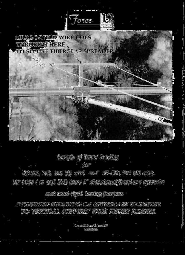
7 f) Check that the nuts are tight and that the cables are running towards the center of the antenna. 5) If the EF-140S is used as a stand-alone: a) Mount the vertical spreader support on the mast side of the mounting plate using U-bolts, lock washers and nuts. Align the support with the 1/2" hole lined up and so that the spreader, when passed through the hole, will be perpendicular to the element. 6) The center spreader is a composite design, which is a total of 48" (4 feet) long. It is designed so that it is strong, yet can be moved to one side to enable reaching the farthest tuning jumper point. a) Locate the spreader, which has fiberglass at both ends. b) Slide the spreader through the center support tube that is welded to the element-to-boom mounting plate. c) The securing pin through the support and spreader (also Copper-Weld wire) is added after tuning is completed. 7) Working on one side ("A" or "B") at a time: a) Slip two (2) 1/8" cable clamps over the free end of both cables and keep them on the outboard side of the spreader (towards the element tip). b) Slide one end of the linear loading cable through the hole at the end of the spreader (on the appropriate end of the spreader). c) Bring the free end downward and back under the spreader and apply enough tension to take up the slack in the cable. c1) The COPPER-WELD wire is quite stiff, so be careful. c2) It is not necessary to put a lot of tension on the wire. c3) Be careful not to distort the spreader with too much tension. d) Pass the free end through the cable clamp that is already on the cable, using the one closest to the spreader. d1) It might be wise to not fully secure the cable clamps on the linear loading cable wire at this time. This will allow adjustments to make the element nice and symmetrical. d2) The other clamp is used to secure the tuning jumper. d3) Position the clamp towards the end of the wire, making the tightest loop. e) IMPORTANT: e1) The wire from one side does not cross over to the other side. The two wires on each side, plus the tuning jumper make a single loop for that side - and that side only. e2) Crossing the wires across the spreader to the other side will not work! f) Position the cable clamp so that the body (not the "U") is on the cable going back out to the outer insulator and tighten the nuts on the cable clamp. It is not necessary to "crunch" these nuts. Tighten only enough so that the cable is visually compressed and physically secure. g) Follow this same procedure for the companion cable on this element half. NOTE: these elements should be installed with some droop still present (i.e. not straight). This is because to make the loading guys tight creates compression on the element and can actually cause it to be less strong than if there were no guys at all. DW-Manual-EF140SN1-007 FORCE 12 EF-140S, 140S/H Assembly Instructions Page 7 of 26
8 8) Attach the linear loading wires in a similar manner on the other side. a) Check for a nice, symmetrical look to the element. b) Secure the cable clamps on the linear loading. 9) Position and secure the tuning jumper as follows: a) Note that the tuning jumper is made of solid material and is bent into a "V" formation. The "V" goes UP. The bent ends go OUT. b) Measuring from the center spreader, 16" to the tuning jumper and cable clamp will center the antenna at about c) 18" will center higher, to about MHz d) 14" will center lower, to about MHz e) The actual setting will vary somewhat, due to actual location and tension in the loading wires. 10) 11) Attach the tuning jumper on the other side, as above. The antenna is now ready for mounting. V. MOUNTING TO THE MAST (stand-alone antenna) 1) If this is a conversion for a C-3 to a C-4, C-3S to C-4S, or C-3SS to C-4SS, proceed to VI. 2) If you are here, the EF-140S is going to be mounted to a mast. 3) Notice that the mast will actually pass through the linear loading. To accomplish this, one linear loading wire is removed from the spreader during installation. 4) Identify the loading wire that needs to be temporarily removed from the spreader. a) Loosen the cable clamp and carefully slide the wire back out of the center spreader. 5) The EF-140S can now be raised into the desired position and secured to the mast with the pair of 2" U-bolts and saddles. These will clamp on to smaller masts as well as 2". 6) Once in position, re-attach the linear loading wire temporarily removed. VI. MOUNTING to the C-3 boom, making a C-4; a C-3S into a C-4S; or a C-3SS to a C-4SS. 1) As an option, the matching coil, balun and feed line can be attached now or after reattachment to the mast (see next section). 2) Note that the balance has now changed. DW-Manual-EF140SN1-007 FORCE 12 EF-140S, 140S/H Assembly Instructions Page 8 of 26
9 3) Loosen the Easy-On plate attached to the boom and slide it towards the EF-140S antenna about a foot (12"), or until the antenna balances again. The antenna can be re-balanced again once it is on the mast. 4) Carefully re-attach the C-4, C-4S, or C-4SS (formerly C-3, C3S, C-3SS) to the mast as before. VII. TUNING 1) Place the helical hairpin match over the bolts, so that it is pointing away from the center of the antenna. Check to ensure that the coil turns are not touching each other (not shorting). 2) Attach the feed line to the two bolts at the center, with the lock washer and nut. The supplied round terminals should be used to make a good connection to the screws. a) If a balun is used, such as a Force 12 B-1, attach the leads to the screws as above and plug the feed line into the other end of the balun. b) If coax is used directly, split about 3" of the coax and solder the round terminals to the coax. Slip the terminals over the screws and secure with the ny-loc nuts. Wind the coax into an RF choke by making 8 turns of about 10" diameter and tape or otherwise bind the coil together so that it cannot come apart. c) Secure the coax feed line to the mast, making sure there is sufficient coax to coil around the mast if a rotator is used. 3) Using a VSWR meter, read the VSWR. If it is not less than 1.3:1 in the band, adjust the hairpin by spreading or pushing together the coil for the lowest VSWR in the band. 3a) The spreader can be moved closer through the center support for ease in reaching the farthest tuning connection. 3b) If the 1:1 point is higher than desired, move the jumpers on both sides of the driver element inward towards the center and test it again. If lower than desired, move the jumpers outward. A readjustment of the hairpin might be required. 3c) If adjusted at about 15' above ground, the antenna will shift less than 15 khz upward as it is raised. 3d) The VSWR will also change slightly, due to the impedance changing as the antenna is raised (this is not unique to this antenna - just a fact!). The hairpin can be re-adjusted once or twice as necessary to compensate, noting which direction it needs to go (turns wider or closer together). 4) After tuning is complete, insert the Copper-Weld wire through the center support and through the spreader. Bend down both sides. This will keep the spreader from moving. 5) Check the VSWR on other antennas in the area (i.e. on the mast) to be sure this antenna has not de-tuned them. If the VSWR has not changed, the interaction is minimal, but the front-toback ratio of the other antenna(s) might have been lessened. This antenna can be mounted parallel to the other booms for the least interaction potential. It has been DW-Manual-EF140SN1-007 FORCE 12 EF-140S, 140S/H Assembly Instructions Page 9 of 26
10 specifically designed for high reactance with other bands; however, coupling can still occur. VIII. FINAL CHECKOUT 1) Apply power and have fun. Notice... PLEASE BE CAREFUL AND DO NOT LET THIS ANTENNA COME INTO CONTACT WITH POWER LINES OR OTHER DANGERS. YOU CAN BE INJURED OR KILLED BY IMPROPER HANDLING OF THIS ANTENNA. Thank you for selecting our product. We hope you enjoy using it. Force 12 Warranty, Limitation of Liability Force 12 products are warranted for a period of one year from date of purchase. Warranty covers defects in manufacturing and workmanship. Force 12 has the discretion of honoring the warranty if the product appears to have been abused, used in a manner that exceeds the specifications of the unit, or a use for which the product was not designed. This warranty does not cover transportation, installation, punitive, or other costs that may be incurred from warranty repair, or installation. Force 12 must be notified and warranty repair authorized (only by Force 12 who issues an RMA) before the company will accept any product returns. Please advise the date of purchase, model number, serial number (if applicable) and a brief description of the problem. 30% restocking fee on products returned unused with RMA issued by Force 12 at the sole discretion of Force 12 The customer, installer and user of these products individually and collectively acknowledge that these products can cause injury or death and individually and collectively accept full responsibility and liability for any and all personal and property damage (direct, indirect and punitive) caused during installation and/or use of these products and hold Force 12 harmless for such damage. (warranty notice date 10/15/2004) DW-Manual-EF140SN1-007 FORCE 12 EF-140S, 140S/H Assembly Instructions Page 10 of 26

11 DW-Manual-EF140SN1-007 FORCE 12 EF-140S, 140S/H Assembly Instructions Page 11 of 26

12 DW-Manual-EF140SN1-007 FORCE 12 EF-140S, 140S/H Assembly Instructions Page 12 of 26

13 DW-Manual-EF140SN1-007 FORCE 12 EF-140S, 140S/H Assembly Instructions Page 13 of 26

14 DW-Manual-EF140SN1-007 FORCE 12 EF-140S, 140S/H Assembly Instructions Page 14 of 26

15 DW-Manual-EF140SN1-007 FORCE 12 EF-140S, 140S/H Assembly Instructions Page 15 of 26

16 DW-Manual-EF140SN1-007 FORCE 12 EF-140S, 140S/H Assembly Instructions Page 16 of 26

17 DW-Manual-EF140SN1-007 FORCE 12 EF-140S, 140S/H Assembly Instructions Page 17 of 26
18 DW-Manual-EF140SN1-007 FORCE 12 EF-140S, 140S/H Assembly Instructions Page 18 of 26
 INDIVIDUAL ELEMENT BUNDLES")


19 TYPICAL ELEMENT BUNDLE, ALL ELEMENTS (Model XR-5 shown) INDIVIDUAL ELEMENT BUNDLES (Model XR-5 shown) A and B MARKINGS ON ELEMENT PIECES A1 & B1 identify they are part of element #1. DW-Manual-EF140SN1-007 FORCE 12 EF-140S, 140S/H Assembly Instructions Page 19 of 26

20 DW-Manual-EF140SN1-007 FORCE 12 EF-140S, 140S/H Assembly Instructions Page 20 of 26

21 DW-Manual-EF140SN1-007 FORCE 12 EF-140S, 140S/H Assembly Instructions Page 21 of 26

22 DW-Manual-EF140SN1-007 FORCE 12 EF-140S, 140S/H Assembly Instructions Page 22 of 26

23 DW-Manual-EF140SN1-007 FORCE 12 EF-140S, 140S/H Assembly Instructions Page 23 of 26

24 DW-Manual-EF140SN1-007 FORCE 12 EF-140S, 140S/H Assembly Instructions Page 24 of 26

25 DW-Manual-EF140SN1-007 FORCE 12 EF-140S, 140S/H Assembly Instructions Page 25 of 26
26 NOTES....LAST PAGE. DW-Manual-EF140SN1-007 FORCE 12 EF-140S, 140S/H Assembly Instructions Page 26 of 26
M2 Antenna Systems, Inc. Model No: VLP16
 M2 Antenna Systems, Inc. Model No: 100-600VLP16 SPECIFICATIONS: Model... 100-600VLP16 Frequency Range... 100-600 MHz Cont. *Gain... 9.64 dbi Front to back... 12 db Typical Beamwidth... E=64 / H=70 Feed
Tripod Setup Guide (M-TPx)
") Items needed: 1/2 inch wrench, mast level (M-MLA), medium size wire cutters, crescent wrench, all-purpose grease, tape measure, tie wraps, redi-mix cement (optional), shovel (optional), sledge hammer (for
Items needed: 1/2 inch wrench, mast level (M-MLA), medium size wire cutters, crescent wrench, all-purpose grease, tape measure, tie wraps, redi-mix cement (optional), shovel (optional), sledge hammer (for
FIRST TEAM SPORTS, INC Storm Portable Series Assembly Instructions
 FIRST TEAM SPORTS, INC Storm Portable Series Assembly Instructions WARNING! WARNING! WARNING! THIS BASKETBALL SYSTEM IS SPRING LOADED AND SHIPPED UNDER TENSION. ATTEMPTING TO ASSEMBLE OR DISASSEMBLE ANY
QUALITY ALUMINUM BOAT LIFTS, INC. INSTRUCTIONS. Dominator Lake Lift
 INSTRUCTIONS Dominator Lake Lift PHONE:251-986-3882 * FAX:251-986-3136 QABLDOMINATORINST.2014 P a g e 1 Quality Aluminum Boat Lifts, INC. Installation Instructions: Dominator Lake Lift Thank you for your
2012-June-12 SECOND DRAFT Hobie Getaway Spinnaker Installation Instructions
 SECTION A: INTRODUCTION This unofficial set of installation instructions was written for a 2009 Hobie Getaway, using a 2012 Hobie Spinnaker Kit 20999020. Note from the Author: I had never seen this kit
Final Assembly Instructions Bikes with Quill Stems
 Final Assembly Instructions Bikes with Quill Stems Thank you for buying your new bicycle from L.L.Bean. Read these instructions carefully before beginning the final assembly. Prior to shipping, our expert
602 STRINGING MACHINE OWNER'S MANUAL
 PROGRESSION 602 STRINGING MACHINE OWNER'S MANUAL AL Issue 1- April 2000 Copyright 2000 GAMMA Sports - All Rights Reserved PROGRESSION 602 STRINGING MACHINE TABLE OF CONTENTS PAGE 1... WARRANTY PAGE 2...
TOWER INSPECTION REPORT
 3010 S. Hwy 77, Suite 600 Waxahachie, Texas 75165 http://ctctower.com Office: 972/923-9504 Fax: 972/923-9619 TOWER INSPECTION REPORT PREPARED FOR MR. CUSTOMER 1,563 GUYED TOWER NEAR CITY, STATE JANUARY
IMPORTANT: RECEIVING INSTRUCTIONS:
 Instruction Sheet Sidewinder Mechanical Bender IMPORTANT: RECEIVING INSTRUCTIONS: Visually inspect all components for shipping damage. If any shipping damage is found, notify carrier at once.shipping damage
SERIES 2 RAMP OWNER S MANUAL TOOLS REQUIRED: BEFORE YOU BEGIN... Read and understand these instructions before beginning a ramp setup.
 SERIES 2 RAMP OWNER S MANUAL BEFORE YOU BEGIN... Read and understand these instructions before beginning a ramp setup. Use caution and care for your back when lifting, pushing, pulling, folding or unfolding
DM-RD (English) Dealer s Manual. ROAD Rear Derailleur RD-9000 RD-6800 RD-5800 RD-4700
 Dealer s Manual. ROAD Rear Derailleur RD-9000 RD-6800 RD-5800 RD-4700") (English) DM-RD0003-09 ROAD Rear Derailleur Dealer s Manual RD-9000 RD-6800 RD-5800 RD-4700 CONTENTS IMPORTANT NOTICE...3 TO ENSURE SAFETY...4 LIST OF TOOLS TO BE USED...6 INSTALLATION...8 Chain length...
(English) DM-RD0003-09 ROAD Rear Derailleur Dealer s Manual RD-9000 RD-6800 RD-5800 RD-4700 CONTENTS IMPORTANT NOTICE...3 TO ENSURE SAFETY...4 LIST OF TOOLS TO BE USED...6 INSTALLATION...8 Chain length...
600 / 600FC OWNER'S MANUAL
 PROGRESSION 600 / 600FC OWNER'S MANUAL Issue 2 / Version E - Dec. 10, 1997 Copyright 1997 GAMMA Sports - All Rights Reserved PROGRESSION 600 / 600FC OWNER'S MANUAL TABLE OF CONTENTS PAGE 1... WARRANTY
Deluxe Gourd Racks I D E G A. Parts List. Shown above are parts for the two-level, Deluxe Gourd Rack (DGR 12V)with 12 arms for vertically hung gourds.
with 12 arms for vertically hung gourds.") Deluxe Gourd Racks H F K I D E J C G A Shown above are parts for the two-level, Deluxe Gourd Rack (DGR V)with arms for vertically hung gourds. Parts List Code Quantity A B C D E F G H I J 6, or 4 6, or
Deluxe Gourd Racks H F K I D E J C G A Shown above are parts for the two-level, Deluxe Gourd Rack (DGR V)with arms for vertically hung gourds. Parts List Code Quantity A B C D E F G H I J 6, or 4 6, or
Lock-N-Load. Bullet Feeder
 Lock-N-Load Bullet Feeder table of contents steps Overview... 2 List of required hand tools... 2 1: Mounting the Bullet Feeder to the Bench... 3 2: Mounting the Bullet Feed Hopper... 4 3: Bullet Feed Hopper
OWNER'S MANUAL. Copyright 1999 ATS - All Rights Reserved
 OWNER'S MANUAL AL Issue 2 - August 19, 1999 Copyright 1999 ATS - All Rights Reserved OWNER'S MANUAL TABLE OF CONTENTS PAGE 1... WARRANTY PAGE 2... ASSEMBLY INSTRUCTIONS PAGE 4... MOUNTING THE RACQUET PAGE
Front derailleur. Dealer's Manual SORA FD-R3000 FD-R3030 CLARIS FD-R2000 FD-R2030. ROAD MTB Trekking. City Touring/ Comfort Bike DM-RBFD001-01
 (English) DM-RBFD001-01 Dealer's Manual ROAD MTB Trekking City Touring/ Comfort Bike URBAN SPORT E-BIKE Front derailleur SORA FD-R3000 FD-R3030 CLARIS FD-R2000 FD-R2030 CONTENTS IMPORTANT NOTICE... 3 TO
Caliber Sled Wheels Assembly Instructions for PN and 13579
 Caliber Sled Wheels Assembly Instructions for PN 13576 and 13579 Caution: Read all instructions before assembling or using Sled Wheels. Follow the steps in order. Only use Sled Wheels as intended, following
Troyer s Gourd Rack 8 unit F R H O P
 B E A D I M-N L Vertical Parts F R H O P Horizontal Parts C G J Updated 11/16 Parts List A: Top of Pole B: Bottom of Pole C: 48 Ground Stake D: Top Perch rods 48 long E: Hub F: Rope Winder w/ attached
OWNER'S MANUAL. Copyright 2003 GAMMA - All Rights Reserved
 OWNER'S MANUAL AL Issue 1 - December 2003 Copyright 2003 GAMMA - All Rights Reserved OWNER'S MANUAL TABLE OF CONTENTS PAGE 1... WARRANTY PAGE 2... ASSEMBLY INSTRUCTIONS PAGE 4... MOUNTING THE RACQUET PAGE
Stand-N-Fish FULL DETAIL INSTALLATION INSTRUCTIONS
 1 Stand-N-Fish FULL DETAIL INSTALLATION INSTRUCTIONS Thank you for purchasing the incredible new Stand-N-Fish Kayak Fishing System. Once installed on your kayak the Stand-N-Fish will take your kayak fishing
Marine 6-Boat Free-Standing Racks SKU: Updated November 2011
 Marine 6-Boat Free-Standing Racks SKU: 30-061 Updated November 011 Contains: Marine -Boat Free-Standing Racks (SKU 1-003) Marine 3 rd Boat Expansion Racks (SKU 1-0303) Marine Back Legs (SKU -001) 3 Sets
Installation Instructions
 116-3027, 116-3017 X-Pando Adjustable Steel Protector Installation Instructions 1404 N. Marshall Ave. El Cajon CA. 92020 For technical support call us at (800) 368-3075 NB 6/28/10 607-0112 Step 1. Mounting
X-6 STRINGING MACHINE OWNER'S MANUAL. Issue 1 - May Copyright 2004 GAMMA Sports - All Rights Reserved
 X-6 STRINGING MACHINE OWNER'S MANUAL Issue 1 - May 2004 Copyright 2004 GAMMA Sports - All Rights Reserved OWNER'S MANUAL GAMMA X-6 TABLE OF CONTENTS PAGE 1... WARRANTY PAGE 2... FEATURES PAGE 3...ASSEMBLY
Final Assembly Instructions Bikes with 16 Wheel Size
 Final Assembly Instructions Bikes with 16 Wheel Size Thank you for buying your new bicycle from L.L.Bean. Read these instructions carefully before beginning the final assembly. Prior to shipping, our expert
Wellhead Mast. Installation and Operation Guide. Nanometrics Inc. Kanata, Ontario Canada
 Installation and Operation Guide Nanometrics Inc. Kanata, Ontario Canada 2001 2005 Nanometrics Inc. All Rights Reserved. Installation and Operation Guide The information in this document has been carefully
WINCH MOUNT KIT OWNER S MANUAL
 WINCH MOUNT KIT For KAWASAKI ATVs OWNER S MANUAL MODEL NUMBER: 25-2150 CUSTOMER MUST RECEIVE A COPY OF THIS OWNER S MANUAL AT TIME OF SALE 2005 Cycle Country Accessories Corp. 4/10/12 MAN0097 9 Please
Cable Replacement Instructions for R-Series Roust-A-Bout 100/150/250
 Cable Replacement Instructions for R-Series Roust-A-Bout 100/150/250 US 7514 Alabonson Road Houston, TX 77088 phone: 281-999-6900 fax: 281-999-6966 Canada 1721 Bishop St. Unit #4 Cambridge, ON N1T 1N5
Final Assembly Instructions Bikes with Threaded Headsets
 Final Assembly Instructions Bikes with Threaded Headsets Thank you for buying your new bicycle from L.L.Bean. Read these instructions carefully before beginning the final assembly. Prior to shipping, our
SECTION 2 RING MOUNT
 SECTION 2 RING MOUNT Rotax aircraft engines are manufactured and supported by Rotax GmbH of Austria. Read and understand the Rotax manuals completely before starting with the engine installation, as they
Side-of-Pole Mount for 1 Module (SPM1) For Module Types A & B
 For Module Types A & B") Side-of-Pole Mount for 1 Module (SPM1) For Module Types A & B ASSEMBLY INSTRUCTIONS step-by-step assembly and installation Version 1, Rev A PCN 080311-2 SP3363-1 Side-of-Pole Mount for 1 Module (SPM1)
Side-of-Pole Mount for 1 Module (SPM1) For Module Types A & B ASSEMBLY INSTRUCTIONS step-by-step assembly and installation Version 1, Rev A PCN 080311-2 SP3363-1 Side-of-Pole Mount for 1 Module (SPM1)
8MAY15 US RACK, Inc Falcon Drive, Madera, CA
 8MAY15 US RACK, Inc. - 2850 Falcon Drive, Madera, CA 93637-559-661-3050 INSTRUCTIONS for Bedrail-mounted MOTORCYCLE RACK, Model 2001-4TRA WARNING: Do NOT attempt to install or use this rack without following
DM-FD (English) Dealer's Manual. Front derailleur FD-M9000 FD-M9020 FD-M9025 FD-M8000 FD-M8020 FD-M8025 FD-M612 FD-M617 FD-M618 FD-M672
 Dealer's Manual. Front derailleur FD-M9000 FD-M9020 FD-M9025 FD-M8000 FD-M8020 FD-M8025 FD-M612 FD-M617 FD-M618 FD-M672") (English) DM-FD0003-04 Front derailleur Dealer's Manual FD-M9000 FD-M9020 FD-M9025 FD-M8000 FD-M8020 FD-M8025 FD-M612 FD-M617 FD-M618 FD-M672 FD-M677 CONTENTS IMPORTANT NOTICE... 3 TO ENSURE SAFETY...
(English) DM-FD0003-04 Front derailleur Dealer's Manual FD-M9000 FD-M9020 FD-M9025 FD-M8000 FD-M8020 FD-M8025 FD-M612 FD-M617 FD-M618 FD-M672 FD-M677 CONTENTS IMPORTANT NOTICE... 3 TO ENSURE SAFETY...
Front derailleur. Dealer's Manual FD-M9000 FD-M9020 FD-M9025 FD-M8000 FD-M8020 FD-M8025 FD-M612 FD-M617 FD-M618 FD-M672 FD-M677
 (English) DM-FD0003-05 Front derailleur Dealer's Manual FD-M9000 FD-M9020 FD-M9025 FD-M8000 FD-M8020 FD-M8025 FD-M612 FD-M617 FD-M618 FD-M672 FD-M677 CONTENTS IMPORTANT NOTICE... 4 TO ENSURE SAFETY...
This document to be used with Hurley traditional Davits
 ~ InstructIon Manual ~ This document to be used with Hurley traditional Davits WarnIngs WarnIng - Failure to install, maintain, protect, and operate the system properly can cause malfunction resulting
Hot Tapping Machine. OPERATIONS MANUAL and OPERATING INSTRUCTIONS
 262-2040 Hot Tapping Machine For performing 1/4 6 Hot taps 285 psi or less. Municipal Water, Sewage, & Building Services Use OPERATIONS MANUAL and OPERATING INSTRUCTIONS WARNING: These instructions are
Pre-Paint>Fuselage>Empennage>Fit vertical tail fin. Objectives of this task: Materials and equipment required: Fit the spar extender
 Pre-Paint>Fuselage>Empennage>Fit vertical tail fin Objectives of this task: To fit the vertical tail fin to the fuselage, including fitting the static probe, static tube, optional strobe light wiring and
TRI-POD SETUP. Guidelines for Typical Field Setup. Site Selection
 TRI-POD SETUP Guidelines for Typical Field Setup Site Selection Use the following guidelines to help you choose an appropriate site for setting up the Station and protecting against field hazards. When
Assembly Guide ST200 FUNCTIONAL TRAINER
 Assembly Guide ST200 FUNCTIONAL TRAINER Assembly Guide ST200 FUNCTIONAL TRAINER To avoid possible damage to this Functional Trainer, please follow these assembly steps in the correct order. Before proceeding,
OWNERS MANUAL. Model Shown with optional Primary Mooring Cleats. Portable Mooring System SAFETY OPERATION MAINTENANCE PARTS
 OWNERS MANUAL Model 2400 Shown with optional Primary Mooring Cleats. Portable Mooring System SAFETY OPERATION MAINTENANCE PARTS CAUTION: Before using your new Pier Tender, read rules for Safety, Operation,
C - SERIES. Height Adjustable Portable Goal Supports. Installation & Owner s Instructions C1000 C2000. Made in the USA
 C - SERIES Height Adjustable Portable Goal Supports C1000 C2000 Installation & Owner s Instructions Made in the USA This manual explains the proper installation, operation, and maintenance of your Schutt
Installation and Training Manual
 AirForce1 Tower Kit Installation and Training Manual FuturEnergy Limited Ettington Park Business Centre Stratford upon Avon CV37 8BT +44 (0)1789 451070 Table of Contents Safety Notes... 3 Parts Supplied
COASTAL IN-BOOM FURLING SYSTEM. Installation Manual
 COASTAL IN-BOOM FURLING SYSTEM Installation Manual 1 TABLE OF CONTENTS Page Number 3. Disclaimer 4. Components packing list & required tools 5. Gooseneck bracket location 6. Installation sail track 7.
Design Based Anchoring 2009 FORD F-150
 Design Based Anchoring OWNERS MANUAL USERS MANUAL 2008 Chief Automotive Technologies. CHIEF'S LIMITED ONE-YEAR WARRANTY & LIABILITY Chief Automotive Technologies warrants for one year from date of installation
VERSA BIKE RACK INSTRUCTIONS
 VERSA BIKE RACK INSTRUCTIONS Models #8, 8 Important This rack is designed for use with a or. receiver hitch. The rack is designed to hold a maximum of two bicycles. Do not use it for anything other than
#59114 Rola 2-Bike Rack Carrier (Shown Assembled) (A) (C) (B)
 (A) (C) (B)") Use for Parts: #59114 Rola -Bike Rack System #59115 Rola 1-Bike Add-On TOOLS REQUIRED 10mm or 13/3 Socket & Wrench #59114 Rola -Bike Rack Carrier (Shown Assembled) Tray Attachment Hardware: (3) Plastic
Use for Parts: #59114 Rola -Bike Rack System #59115 Rola 1-Bike Add-On TOOLS REQUIRED 10mm or 13/3 Socket & Wrench #59114 Rola -Bike Rack Carrier (Shown Assembled) Tray Attachment Hardware: (3) Plastic
How I Manage my Mast and Spiderbeam Antenna
 In this blog post, I will cover the basic process used to mount the Spiderbeam antenna onto the mast (by myself) and to raise the antenna with no assistance, other than my Easy Mast device. I like to name
Instruction and Practice Manual
 Instruction and Practice Manual Axiom Sports Manufacturing A Division of Fitec International 3525 Ridge Meadow Parkway Memphis, TN 38175 (901) 366-9144 www.axiomsports.com 1 Thank you for purchasing the
Falcon 3 145, 170, 195 and Tandem Owner / Service Manual
 Falcon 3 145, 170, 195 and Tandem Owner / Service Manual January 2007 - Second Edition Removing The Sail From The Airframe And Short Packing The Glider Many maintenance and repair procedures will require
Sanibel Owners Manual
 Sanibel 36-600 Owners Manual TM Specifications Length (Hull):... 36 inches Height (Mast):... 51.5 inches Height (Overall):... 69 inches Beam:... 7.5 inches Radio: JR Beat Gear w/sail winch servo Sail area:
Before you start! Is iwalk 2.0 right for you?
 Before you start! Is iwalk 2.0 right for you? Physical Abilities Requirements 1. Stair Test Before your injury, could you easily walk up and down stairs at normal speed, without using the hand rail? 2.
2019 MADONE ASSEMBLY MANUAL
 2019 MADONE ASSEMBLY MANUAL 2019 MADONE Rim brakes and Di2 drivetrain Rim brakes and mechanical drivetrain Disc brakes and Di2 drivetrain Disc brakes and mechanical drivetrain TABLE OF CONTENTS Common
Pressure Dump Valve Service Kit for Series 3000 Units
 Instruction Sheet Pressure Dump Valve Service Kit for Series 000 Units. Overview The Nordson pressure dump valve is used to relieve hydraulic pressure instantly in Series 00, 400, 500, and 700 applicator
CO V E R S TA R AU TO MAT I C S A F E T Y CO V E R INSTALLATION GUIDE
 CO V E R S TA R AU TO MAT I C S A F E T Y CO V E R DECKMOUNT SYSTEM INSTALLATION GUIDE SECTIONS System Parts Reference...3 Standard Top Track...4-6 Mechanism... 7-10 Cover Fabric...11-16 Home Owner & Builder
SKYBIRD TRAP OWNER S / OPERATOR S MANUAL PARTS AND ASSEMBLY INSTRUCTIONS
 SKYBIRD TRAP PART NO. 40903 OWNER S / OPERATOR S MANUAL PARTS AND ASSEMBLY INSTRUCTIONS WARNING: THIS MACHINE CAN CAUSE SERIOUS INJURY OR DEATH! THOROUGHLY READ INSTRUCTIONS AND SAFETY INFORMATION BEFORE
Front derailleur. Dealer's Manual XTR FD-M9000 FD-M9020 FD-M9025 DEORE XT FD-M8000 FD-M8020 FD-M8025 DEORE FD-M612 FD-M617 FD-M618 SLX FD-M672 FD-M677
 (English) DM-FD0003-06 Dealer's Manual ROAD MTB Trekking City Touring/ Comfort Bike URBAN SPORT E-BIKE Front derailleur XTR FD-M9000 FD-M9020 FD-M9025 DEORE XT FD-M8000 FD-M8020 FD-M8025 DEORE FD-M612
CONFER ABOVE GROUND CURVE STEP / ABOVE GROUND CURVE STEP SYSTEM ASSEMBLY AND INSTALLATION MANUAL
 SAVE THESE INSTRUCTIONS DEALER/INSTALLER: GIVE TO HOMEOWNER CONFER ABOVE GROUND CURVE STEP / ABOVE GROUND CURVE STEP SYSTEM ASSEMBLY AND INSTALLATION MANUAL Model CCX-AG Note: 40 lbs. of sand required!
Front derailleur. Dealer's Manual DURA-ACE FD-R9100 ULTEGRA FD-R FD ROAD MTB Trekking. City Touring/ Comfort Bike DM-RAFD001-03
 (English) DM-RAFD001-03 Dealer's Manual ROAD MTB Trekking City Touring/ Comfort Bike URBAN SPORT E-BIKE Front derailleur DURA-ACE FD-R9100 ULTEGRA FD-R8000 105 FD-5801 Procedures for cable tension adjustment
Pressure Dump Valve Service Kit for Series 2300 Units
 Instruction Sheet Pressure Dump Valve Service Kit for Series 00 Units. Overview The Nordson pressure dump valve is used to relieve hydraulic pressure instantly in Series 00 applicator tanks when the unit
CRUZBIKE Quest 2.0 Assembly
 CRUZBIKE Quest 2.0 Assembly CRUZBIKE Quest 2.0 Assembly... 1 General notes on assembly... 2 Un box and evaluate the frame and major parts... 2 Unfold the rear swing arm and arrange the frame... 3 Rear
Installation Instructions MODEL VSTI-A020 Tank Indicator Installation Model: VSTI-A020, Stainless Reverse Read System Versa Steel Inc. Guide Cables No
 Tank Indicator Installation Model: VSTI-A020, Stainless Reverse Read System Guide Cables No Guide Cables 1 August 4, 2011 Assembly Instructions: (Shown with a 2 board, 12 ft kit) ITEM NO. PART NUMBER DESCRIPTION
ST Shimano Total Integration. Technical Service Instructions. General Safety Information SI-6CT0B
 Technical Service Instructions SI-6CT0B t ST-4400 Shimano Total Integration Shimano Total Integration Features The Shimano Total Integration TIAGRA series features a dual action control lever which actuates
Tube-Line Accelerator Spinner Kit
 Tube-Line Accelerator Spinner Kit Operator's Manual PP-00799 (19/09/11) 2 TO THE OWNER This manual contains information concerning the adjustment, assembly and maintenance of your Tube-Line Spinner Kit.
Page 1. Single Scull Car Rack Assembly and User s Manual " "
 Page 1 Single Scull Car Rack Assembly and User s Manual Page 2 Items in the box: (2) V cradles (2) 4 rails (1) 1 3/4 X 18 rail coupler (4) 1/4-20 X 4 1/2 bolts (2) 1/4-20 X 2 1/2 bolts (12) 1/4 flat washers
comfort without compromising on performance and to fit your various needs on touring,
 Congratulations on your purchase of Goal-26X. Goal-26X is made to enhance comfort without compromising on performance and to fit your various needs on touring, shopping and communicating. Let s have fun
PROPORTIONING VALVE. Model 150 INSTRUCTION MANUAL. March 2017 IMS Company Stafford Road
 PROPORTIONING VALVE Model 150 INSTRUCTION MANUAL March 2017 IMS Company 10373 Stafford Road Telephone: (440) 543-1615 Fax: (440) 543-1069 Email: sales@imscompany.com 1 Introduction IMS Company reserves
Congratulations on your purchase of a JC Series Performer trike! The Performer JC Series is designed for everything from touring to commuting and
 Congratulations on your purchase of a JC Series Performer trike! The Performer JC Series is designed for everything from touring to commuting and shopping in the city. The JC Series frames are made of
INSTRUCTIONS 360 Y-DROP HAGIE STS 2015
 INSTRUCTIONS 60 Y-DROP HAGIE STS 05 INSTRUCTIONS 60 Y-DROP HAGIE STS 05 INTRODUCTION Before beginning, it s important to know where each mounting bracket fits relative to the row spacing involved. The
Final Assembly Instructions Bikes with Threaded Headsets
 Final Assembly Instructions Bikes with Threaded Headsets Thank you for buying your new bicycle from L.L.Bean. Read these instructions carefully before beginning the final assembly. Prior to shipping, our
A. TO PREPARE THE MACHINE FOR USE.
 INSTRUCTION MANUAL FOR THE ML120 STRINGING MACHINE. CONTENTS: A. TO PREPARE THE MACHINE FOR USE. 1. The assembly of frame with console and tooltray. 2. Fixing the lever of the tension unit. 3. Putting
CONFER IN-GROUND CURVE STEP / IN-GROUND CURVE STEP SYSTEM ASSEMBLY AND INSTALLATION MANUAL
 SAVE THESE INSTRUCTIONS DEALER/INSTALLER: GIVE TO HOMEOWNER CONFER IN-GROUND CURVE STEP / IN-GROUND CURVE STEP SYSTEM ASSEMBLY AND INSTALLATION MANUAL Model CCX-IG Note: 40 lbs. of sand required! SAND
Chapter 2 Rigging. Cutting Wire Rope. Anchoring Wire Rope to Drum. Winding Wire Rope Onto Drum
 Chapter 2 Rigging Cutting Wire Rope The wire rope must be tightly seized on both sides of the point where the wire rope will be cut, as shown in Figure 2-1. Seize the wire rope with either seizing wire
CHAPTER 5 REWIND STARTERS
 GENERAL INFORMATION CHAPTER 5 REWIND S Rewind starters used on vertical shaft Tecumseh engines are top mount horizontal pull style or side mount vertical pull style. Horizontal shaft engines use side mounted
Triple Tine Mechanical Grapple
 Attachment Solutions Triple Tine Mechanical Grapple Operators Manual KENCO Mechanical Grapple Operation Manual 1 TABLE OF CONTENTS 170 State Route 271 Section I. General Information.... 3 Section II. Safety...
INSTRUCTION MANUAL. January 23, 2003, Revision 0
 INSTRUCTION MANUAL Model 810A In-Vitro Test Apparatus for 310B Muscle Lever January 23, 2003, Revision 0 Copyright 2003 Aurora Scientific Inc. Aurora Scientific Inc. 360 Industrial Parkway S., Unit 4 Aurora,
WINSAFE Corp. Operating Instructions For Outrigger Davit. Winsafe Part # WSOR208
 WINSAFE Corp. Operating Instructions For Outrigger Davit Winsafe Part # WSOR208 These instructions must be read and understood by anyone installing or suspending equipment from Winsafe modular beams and
Dealer's Manual ROAD MTB Trekking City Touring/ URBAN SPORT E-BIKE Comfort Bike Front derailleur ALIVIO Non-Series
 (English) DM-MDFD001-02 Dealer's Manual ROAD MTB Trekking City Touring/ Comfort Bike URBAN SPORT E-BIKE Front derailleur ALIVIO FD-M4000 FD-M4020 Non-Series FD-MT400 CONTENTS IMPORTANT NOTICE... 3 TO ENSURE
Ladies Shopper Bike Assembly Manual 28C03
 Ladies Shopper Bike Assembly Manual 28C03 Ecosmo Ltd 1 Know your bike 1. Wheel 2. Rear Derailleur 3. Chain 4. Crank Set 5. Pedal 6. Seat Quick Lock 7. Saddle and Post 8. Frame 9. Front Light 10. Front
Below are the instructions to build a roller-furling unit for under $10. Read the entire process before beginning the project.
 Greg Cowens' $10 PVC Roller Reefing for CP-16's by Greg Cowen Below are the instructions to build a roller-furling unit for under $10. Read the entire process before beginning the project. Materials: 2
310 SERIES TILT-TO-LOAD ROTATOR. The Specialist In Drum Handling Equipment
 OPERATOR S MANUAL FOR MORSE TILT-TO-LOAD DRUM ROTATOR SAFETY INFORMATION: While Morse Manufacturing Co. drum handling equipment is engineered for safety and efficiency, a high degree of responsibility
Thumb Shifter Plus Thumb Shifter
 (English) DM-SL0004-01 Dealer's Manual Thumb Shifter Plus Thumb Shifter Thumb Shifter Plus SL-FT55 SL-TX50 SL-TX30 Thumb Shifter SL-TZ20 IMPORTANT NOTICE This dealer's manual is intended primarily for
Gurney Flap for WRX and STI w/low Profile Trunk Spoiler
 Gurney Flap for 2015+ WRX and STI w/low Profile Trunk Spoiler 2017-12-05 Thank you for purchasing this PERRIN product for your car! Installation of this product should only be performed by persons experienced
Retractable Hose Reel with 3/8" x 50' PVC Hose
 Retractable Hose Reel with 3/8" x 50' PVC Hose Item# 4816153 Owner s Manual Assembly and Operation Instructions MADE IN CHINA Read carefully and understand all ASSEMBLY AND OPERATION INSTRUCTIONS before
MASTER TRUING STAND TS-3. Optional Dial indicator set with brackets Dial indicator bracket set only
 MASTER TRUING STAND TS-3 3 2 1 3 8 9 4 10 7 6 5 12 13 Optional 1555-1 Dial indicator set with brackets 1556-1 Dial indicator bracket set only 49 11 16 14 15 48 32 31 37 38 20 19 17 18 34 39 21 36 22 33
Shifting Lever. Dealer's Manual. RAPIDFIRE Plus SL-M2000 SL-M3010 SL-M4010. Thumb Shifter SL-TZ500. ROAD MTB Trekking. City Touring/ Comfort Bike
 (English) DM-MDSL001-01 Dealer's Manual ROAD MTB Trekking City Touring/ Comfort Bike URBAN SPORT E-BIKE Shifting Lever RAPIDFIRE Plus SL-M2000 SL-M3010 SL-M4010 Thumb Shifter SL-TZ500 CONTENTS IMPORTANT
Santa Fe Cycles Assembly Guide Introduction
 Santa Fe Cycles Assembly Guide Introduction Congratulations on your purchase of your new Santa Fe bicycle. You have purchased a bicycle that has many features and qualities. Please take a few minutes and
LJ1-25 LouieJRtm Tapping Machine
 1/21/08 WARNING: Before using this product, read owners manual and follow all Safety Rules and Operating Instructions. LJ1-25 LouieJRtm Tapping Machine OPERATIONS MANUAL & OPERATING INSTRUCTIONS 30230
Lectric Cycles Mid-Drive Electric Motor Installation
 Lectric Cycles Mid-Drive Electric Motor Installation This write-up describes the installation of a Lectric Cycles electric motor. The model is the e-rad Mid-Drive 750 Watt conversion kit, installed on
M32 CATAMARAN ASSEMBLY MANUAL
 M32 CATAMARAN ASSEMBLY MANUAL 1 M32 CATAMARAN ASSEMBLY MANUAL MANUAL SUMMARY M32 ASSEMBLY Parts and tools Instructions MAST PLATFORM Parts and tools Instructions MAST STEPPING Instructions MAIN HALYARD
E. Test, and if needed, adjust tips of antenna. 1. Mark will test antennas with meter at ground end of feedline bundle. Will take 10 minutes.
 Project Steps Overview: A. Prepare: B. Raise up small antenna. C. Raise up large antenna. D. Connect to new bundle of 4-feedlines pulled up from ground. E. Test, and if needed, adjust tips of large antenna.
Array Solutions 350 Gloria Rd Sunnyvale, TX Phone FAX
 Array Solutions 350 Gloria Rd Sunnyvale, TX 75182 Phone 972-203 2008 FAX 972-203 8811 E-mail: info@arraysolutions.com Installation Instructions AS-AYL-4 WM Array Solutions K9AY Loop Wire/Mast Kit Thank
MODEL CCX-AG CURVE STEP / CURVE STEP SYSTEM
 To reduce the risk of drowning, entrapment, falls, paralysis, electrocution, or other serious injury or death: Dealer/Installer: Give manual to homeowner. Installer: Read "Safe Installation" on p. 2 and
Side-of-Pole Mount for 1 Module (SPM1) For Module Type C
 For Module Type C") Module Type Width Length C 22-27 56-63 Side-of-Pole Mount for 1 Module (SPM1) For Module Type C ASSEMBLY INSTRUCTIONS step-by-step assembly and installation Version 1, Rev A PCN 022212-1 Side-of-Pole Mount
Module Type Width Length C 22-27 56-63 Side-of-Pole Mount for 1 Module (SPM1) For Module Type C ASSEMBLY INSTRUCTIONS step-by-step assembly and installation Version 1, Rev A PCN 022212-1 Side-of-Pole Mount
SAMPLE PAGE. Section 2... Wire Rope
 Section 2...................................................... Wire Rope Never use any kind of clip to directly connect two straight lengths of wire rope to form a continuous piece. Do not make up slings
Road Chain Catcher Installation Instructions (K13-001, K13-006, K SL1, K SL2)
") Road Chain Catcher Installation Instructions (K13-001, K13-006, K13-001-SL1, K13-001-SL2) Description: The K-Edge Road Chain Catcher series is designed to eliminate chain drop on the lowest chainring due
Road Chain Catcher Installation Instructions (K13-001, K13-006, K13-001-SL1, K13-001-SL2) Description: The K-Edge Road Chain Catcher series is designed to eliminate chain drop on the lowest chainring due
Changing Out the Rear Hub and Sprocket on a 2012 Morgan Three Wheeler Calum Fraser 17/07/2015
 Intro The early Three Wheelers had the rear sprocket in a stepped arrangement relative to the front sprocket with the belt overhanging the sprocket on the outside face. While this is probably less of a
White Industries Crank Installation Instructions
 White Industries Crank Installation Instructions Follow these instructions to install both ENO and VBC crank arms and chain rings. When the ENO crank is installed on a 113x68mm bottom bracket, the Q factor
OWNER'S MANUAL LOCK-N-LOAD BULLET FEEDER (PISTOL)
") OWNER'S MANUAL LOCK-N-LOAD BULLET FEEDER (PISTOL) Table of Contents ASSEMBLY ASSEMBLY Pistol Bullet Feeder... Page 3 CHANGE-OVERS The Hornady Lock-N-Load Pistol Bullet Feeder is capable of feeding most
OWNER'S MANUAL LOCK-N-LOAD BULLET FEEDER (PISTOL) Table of Contents ASSEMBLY ASSEMBLY Pistol Bullet Feeder... Page 3 CHANGE-OVERS The Hornady Lock-N-Load Pistol Bullet Feeder is capable of feeding most
Table of content Introduction 5 1. Part 1. Assembly Tools needed for Assembly Glossary Hulls Mounting the beams 7
 Table of content Introduction 5 1. Part 1. Assembly 6 1.1. Tools needed for Assembly 6 1.2. Glossary 6 1.3. Hulls 7 1.3.1. Mounting the beams 7 1.3.2. Fixing the mast rotation cleats 8 1.3.3. Placing the
OPERATING and MAINTENANCE INSTRUCTIONS MAXIS 6K Puller (M6K-M)
") OPERATING and MAINTENANCE INSTRUCTIONS MAXIS 6K Puller (M6K-M) READ AND UNDERSTAND ALL OF THE INSTRUCTIONS AND SAFETY INFORMATION IN THIS MANUAL BEFORE OPERATING OR 04/17 (M6K-M) SERVICING THIS TOOL TABLE
OPERATING and MAINTENANCE INSTRUCTIONS MAXIS 6K Puller (M6K-M) READ AND UNDERSTAND ALL OF THE INSTRUCTIONS AND SAFETY INFORMATION IN THIS MANUAL BEFORE OPERATING OR 04/17 (M6K-M) SERVICING THIS TOOL TABLE
RADROVER REAR RACK INSTALLATION MANUAL
 RADROVER REAR RACK INSTALLATION MANUAL WWW.RADPOWERBIKES.COM We are here to help! Please contact us at SUPPORT@RADPOWERBIKES.COM or 1-800-939-0310 if you have questions. REV022216 Welcome Thanks you for