LEAK TROUBLESHOOTING
|
|
|
- Toby Ezra Walton
- 5 years ago
- Views:
Transcription


1 LEAK TROUBLESHOOTING If you suspect that your TMC isolation system is leaking (most often evidenced by going through air/nitrogen tanks too quickly), this guide will help you to find and fix the problem. Illustrated photos are of a CleanBench Lab Table, but items shown are common for all TMC isolation systems. As with any troubleshooting exercise, the objective is to start with the easiest and most obvious potential leak points, and work towards the hardest. So we suggest you use this order: 1. All fittings. 2. Air filter. 3. Height control valves. 4. The isolation modules. 5. Plumbing schematic. 1. All fittings The fittings you ll find on your system are shown in Figure 1 below: Male Connector, Part Number: KQ2H 07-34AS This fitting has a male 1/8 NPT (National Pipe Thread) on one end and a press-lock connection (red or orange plastic) for ¼ OD flexible tubing on the other end. It is provided as one of two fittings supplied to connect to your air source and at the INPUT port of the supplied air filter & the three height control valves. 1/4x1/8 Brass Reducing Bushing, Part Number: This fitting is supplied in case the 1/8 NPT thread on the Male Connector is too small for the output fitting of your air source. It has a female 1/8 NPT thread on one end and a male 1/4 NPT on the other end. Male Elbow, Part Number: KQ2L 07-34AS Male 1/8 NPT on one end, and the press-lock on the other. This is found at the OUTPUT ports of the air filter and the three height control valves. Union Tee, Part Number: KQ2T 07-00A There are three T s in a 4 isolator system, two coming from the output side of the filter to distribute the air to the input ports of the three height control valves, and one more to distribute the air from Leak Troubleshooting Rev. Dec. 2013
2 the output port of the Master valve (one of the three valves will be controlling two legs) to its own leg and to its Slave leg. All three ends of the Tee are press-lock. Connector (Straight Union), Part Number: KQ2H 07-00A This fitting is a splice for ¼ OD flexible tubing. It is used to connect the short length of special tubing that goes into each leg (at TMC, we call this short length of tubing a pigtail ) to the tubing coming from the output port of its controlling height control valve. Press-lock fittings at each end. Extended Male Elbow, Part Number: KQ2W 07-34AS This fitting is the input at each leg, the tubing connecting to it comes from the output side of its controlling height control valve. It is extended to allow it to reach through the outer post of the leg to the isolation module inside. It has a male 1/8 NPT thread where it goes into the module and a press-lock at the outer end to accept the tubing. FINDING THE LEAK: The most reliable method is by using a commercially available (Home Depot, Lowes, any industrial supply retailer, etc.) leak detection fluid. You simply coat the connections with the fluid (make sure you coat both ends of the fitting). Any leak will result in visible bubbling of the fluid. A solution of soapy water can also work, though not as dependably. FIXING LEAKS AT THE FITTINGS: If you detect a leak at the threaded end of the fitting, first try just tightening the fitting in its threaded connection. If that doesn t work, then remove the fitting (after de-pressurizing the system), clean the threads, and reapply sealing tape (commonly called Teflon tape) to the male threads, and re-install the fitting. If the leak is at a press-lock coupling, remove the tube from the coupling. This is done (again, in a de-pressurized system) by pushing the outer red button in (towards the fitting). This will release the grip the fitting has on the tube. Then you can pull the tube from the fitting. Inspect the end. It should be reasonably square and smooth (including the outside diameter). If necessary, cut it back to meet these conditions, and re-install the tube into the fitting. The method of doing this is to push the tube into the red button until you feel it bottom out, the give the tube a light pull outward. This will seat the internal seal of the fitting. Re-pressurize and re-test with the leak detection fluid. If there is still a leak, then you will have to replace the fitting. You can order the fitting(s) from TMC, using the part numbers mentioned above. Call ( ) or (service@techmfg.com) for prices. NOTE: Make sure you check the fittings at your source (tank, compressor, building air) 2

3 2. Air Filter Part Number The Air Filter you ll find on your system is shown in Figure 2: Using the leak detection fluid described above, check the joint where the clear collection bowl joins the main body of the filter, and around the release valve at the bottom of the bowl. If either area is leaking, there is no fix, and you will have to replace the filter. Call ( ) or for prices. 3

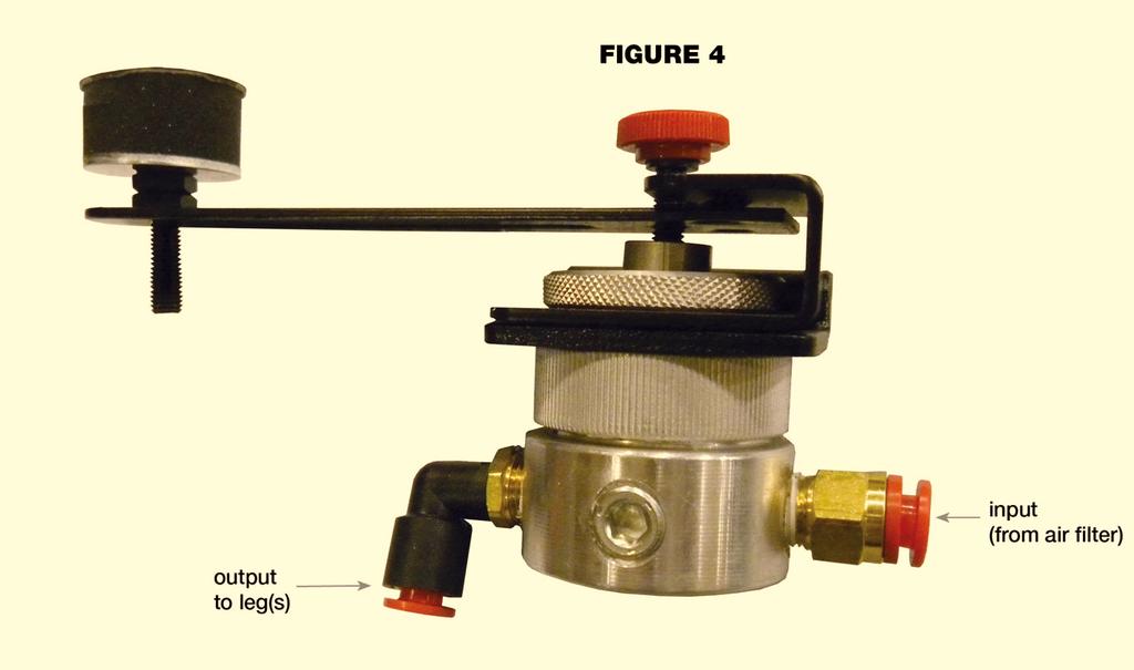
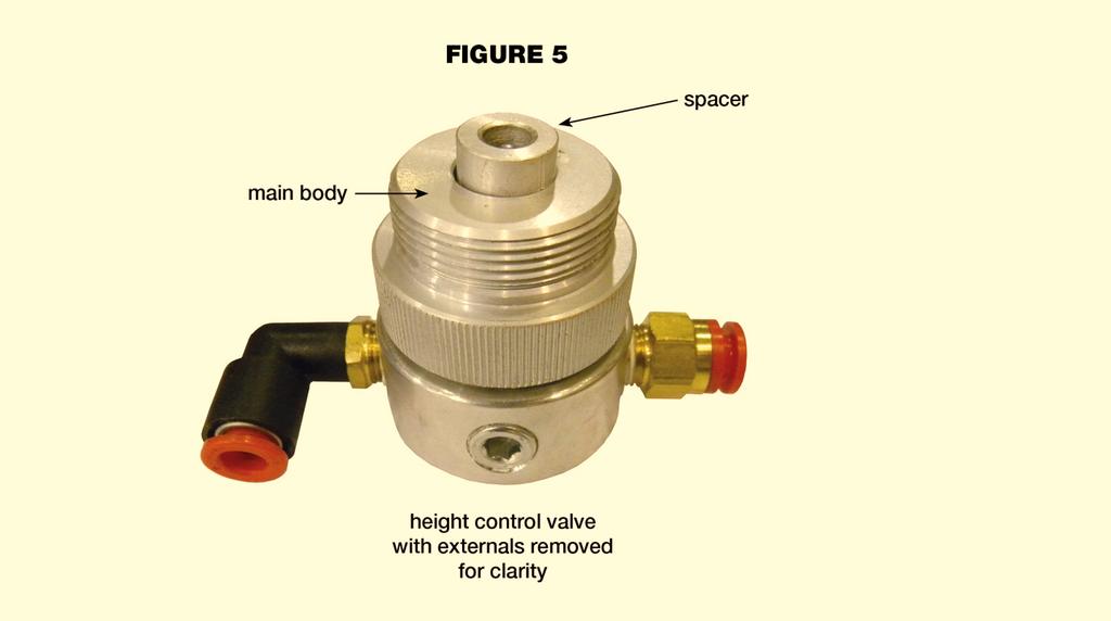
4 3. Height Control Valves Part Number: The Height Control Valves you ll find on your system are shown in Figures 4 and 5): If the leak is at one of the height control valves or an isolation module, the leak can be narrowed down to the specific leg as follows: Make sure that the top is floating correctly, then shut off the air supply at the source and carefully watch to see which isolator deflates the soonest. Now you know which leg has the leak, and you just need to determine whether it is the height control valve or the isolation module. This will be described below: 4
5 5
 to the input of the leg itself ( Extended Male Elbow, see above).")
6 4. Isolation Modules Isolation Module, Part Number: Isolation Module on your system is shown in Figures 3, 6, & 7: Pressurize the system and make sure the table is floating correctly. Go to the leg that deflated the soonest. You ll notice a tube going from the output port of the valve ( Male Elbow, see Figure 6) to the input of the leg itself ( Extended Male Elbow, see above). Find a point in that tube where you can bend it enough to crimp it: NOTE: If there is not be enough slack in the line to accomplish this, you could temporarily replace this tube with a longer piece (you ll have to re-install the original one, as it is necessary for the proper operation of the system) in order to perform this test. Shut off the air supply again, and see if this leg is still the first to deflate. If it does not, then the problem is in the valve. Apply the leak detection fluid at all 4 ports on the periphery of the valve (one input port, marked IN and 3 output port, no marking). One output port will be going to a leg (or legs), and the other 2 will either have plugs or a pressure gage. These are all 1/8 NPT threads, and leaks can be fixed as described earlier. If there is an obvious leak coming from where the valve spacer protrudes though the main body of the valve, or if no leaks are detected, then the problem is internal to the valve. And the recommended fix, at this point, is to replace the valve assembly. Contact TMC for pricing. If this leg is still the first one to deflate, then the problem is in the module. There is one more thing you can try. Un-crimp the tube and use the leak detection fluid you used on the fittings to coat the outside of the diaphragm where the clamp ring seals it against the module. See Figure 7. 6

7 If the fluid bubbles here, then you may still be able to fix the leak by tightening the Allen Head screws that attach the clamp ring to the module. They may have loosened slightly over time, and tightening them could fix the leak. HINT: You will need to adjust the height control valve higher to get enough clearance to get at these screws. We recommend that before you do this, you adjust the supply pressure to no more than 10 psi above the pressure in the leg (the reading on the pressure gage). If there is no leak here, or if tightening the screws does not seal the leak, then you will have to replace the module. You will have to get the top out of the way (because the module comes straight up to remove it), but once you do, the rest of the replacement process is straight-forward. Call ( ) or for prices. Other background information and hints: A. Each valve & isolator is fully tested for leaks before shipping, but it s important to note that a properly functioning system is not completely closed, and will use air. Even ideally, an isolation system will use air at the following rates. Standard Valves: CFM per psi of isolator (valve gage) pressure. Precision Valves: CFM per psi of isolator pressure. As you can see, the air usage for precision valves is 10 times higher than for standard valves. For this reason, we recommend that only house air be used for systems with precision valves. B. Make sure none of the height control valves are plumbed backwards. As stated earlier, the input port of the valve is engraved with the letters IN, and will have the Male Connector straight fitting. The output port will have the Male Elbow fitting and will not be marked. C. Make sure that all three valve lever arms are set at a nominally horizontal position. An arm angled upward may indicate that the red pressurizing screw has been turned too far and the valve is jammed open. 7

8 5. Plumbing schematic 8
Technical Bulletin. Parts and Service News. LPG Lock-Off valve replacement procedures for 4.2 Liter Ford V6
 Equipment Affected Technical Bulletin LPG Lock-Off valve replacement procedures for 4.2 Liter Ford V6 Ford 4.2L V-6 powered tractors with LPG fuel systems. Part Description Discrepancy Fuel Pressure Lock-off
Installation Instructions
 Installation Instructions S65-135 (Circular) S65-136 (Semi-Circular) Air Valve Retrofit For Non-Sectional Classic Washfountain Table of Contents.......................2-6 Metering Air Valve Parts List....................6
SIMPLAIR PIPING TOOL. JXT Company
 SIMPLAIR PIPING INGERSOLL-RAND SIMPLAIR PIPING With push-in fittings and lightweight anodized aluminum pipe, a SimplAir system provides ideal connection throughout your entire air distribution system.
Pressure Dump Valve Service Kit for Series 3000 Units
 Instruction Sheet Pressure Dump Valve Service Kit for Series 000 Units. Overview The Nordson pressure dump valve is used to relieve hydraulic pressure instantly in Series 00, 400, 500, and 700 applicator
INSERT FITTINGS INSERT FITTINGS
 Insert Tee Insert x Female Tee Insert Elbow Insert x Male Elbow Insert Coupling Insert x Male Adapter Insert x Female Adapter Insert Plug POLY and NYLON FITTINGS For use with Poly Tubing Fitting 1/2 3/4
FITTINGS THREAD LUBRICANTS. Fittings 20,000 PSI
 Jetstream offers a wide variety of fittings with various connection types to fit your 20,000 psi application needs. The standard connection types, Type M, MP, and MP Tube lance, are available in standard
PROCEDURE TWO-PLY TESTABLE BELLOWS D 1 OF 5 TWO PLY BELLOWS TEST PROCEDURE
 PROCEDURE TWO-PLY TESTABLE BELLOWS D 1 OF 5 TWO PLY BELLOWS TEST PROCEDURE Prepared by: Pathway Piping Solutions Daniel L. Edgar, PE Pine Valley, Ca 91962 Phone: (619) 473-8248 FAX: (619) 473-8148 Pathway
FOR INSTALLING CO 2 BLENDER KIT (P/N IN BEER SYSTEM
 IMI CORNELIUS INC One Cornelius Place Anoka, MN 55303-623 Telephone (800) 238-3600 Facsimile (612) 22-326 INSTALLATION INSTRUCTIONS FOR INSTALLING CO 2 BLENDER KIT (P/N 111612000 IN BEER SYSTEM SECONDARY
The P-Rod Double by The Airgun Lab Installation Instructions Revision F 08/01/2016 page 1 of 18
 Installation Instructions Revision F 08/01/2016 page 1 of 18 Safety Warning, Terms and Conditions: Each P-Rod Double kit has been designed, manufactured, and tested to function with a standard Benjamin
HPIC D Hydrostatic Test Pump PRODUCT INFORMATION AND OPERATING INSTRUCTIONS
 WIDDER TOOLS HPIC-10000-D Hydrostatic Test Pump PRODUCT INFORMATION AND OPERATING INSTRUCTIONS Description: The WIDDER Hydrostatic Test Systems C Series is a portable, selfcontained, air driven hydrostatic
! WARNING. Model PFC-1-G (direct acting) PFC-1-GR (reverse acting) Modulating Pneumatic Liquid Level Controls INSTRUCTION MANUAL MM-110B
 PFC-1-GR (reverse acting) Modulating Pneumatic Liquid Level Controls INSTRUCTION MANUAL MM-110B") INSTRUCTION MANUAL MM-110B Model PFC-1-G (direct acting) PFC-1-GR (reverse acting) Modulating Pneumatic Liquid Level Controls APPLICATIONS: Use with other pneumatic devices, for liquid level sensing in
INSTRUCTION MANUAL MM-110B Model PFC-1-G (direct acting) PFC-1-GR (reverse acting) Modulating Pneumatic Liquid Level Controls APPLICATIONS: Use with other pneumatic devices, for liquid level sensing in
Installation, Operation, and Maintenance Manual
 Installation, Operation, and Maintenance Manual Welker The information in this manual has been carefully checked for accuracy and is intended to be used as a guide for the installation, operation, and
AKIT1901LM (Metal levers) AKIT1901XM (Cross Handles)
 AKIT1901XM (Cross Handles)") PALLADIAN EXPOSED TUB SET WITH HANDSHOWER AKIT1901LM (Metal levers) AKIT1901XM (Cross Handles) COLORS/FINISHES WARRANTY FEATURES Palladian metal levers or cross handles Floor mounted exposed two handle
PALLADIAN EXPOSED TUB SET WITH HANDSHOWER AKIT1901LM (Metal levers) AKIT1901XM (Cross Handles) COLORS/FINISHES WARRANTY FEATURES Palladian metal levers or cross handles Floor mounted exposed two handle
Pressure Dump Valve Service Kit for Series 2300 Units
 Instruction Sheet Pressure Dump Valve Service Kit for Series 00 Units. Overview The Nordson pressure dump valve is used to relieve hydraulic pressure instantly in Series 00 applicator tanks when the unit
Float Operated Level Controllers
 CONTENTS Float Operated Level Controllers IM0015 Nov. 2014 PAGE Introduction 1 Scope 1 Description 1 Specification 1 Control Installation 2 INTRODUCTION Side Mount Back Mount Prior to installing, the instructions
CAST IRON VALVES FLOAT VALVE
 CAST IRON VALVES FLOAT VALVE NETAFIM CAST IRON VALVES FLOAT VALVE INLINE 25-400MM ANGLE 50-100MM SPECIFICATIONS Manufactured to ISO 9001 Available Valve sizes INLINE Flanged 50mm to 600mm & Threaded 19mm
Installation/Care/Use Manual
 Installation/Care/Use Manual EMASM Surface Mount Bottle Filling Station IMPORTANT THIS IS AN INDOOR APPLICATION ONLY! ALL SERVICE TO BE PERFORMED BY AN AUTHORIZED SERVICE PERSONNEL. TOOLS/ITEMS REQUIRED
INSTRUCTION MANUAL. January 23, 2003, Revision 0
 INSTRUCTION MANUAL Model 810A In-Vitro Test Apparatus for 310B Muscle Lever January 23, 2003, Revision 0 Copyright 2003 Aurora Scientific Inc. Aurora Scientific Inc. 360 Industrial Parkway S., Unit 4 Aurora,
PN LINE. Technical remarks PN 11 PN 13 PN 14 PN 15 PN 17 PN 18 PN 20 PN 23 PN 25 PN 26 PN 27 PN 28 PN 29 PN 37 PN 38 PN 39 PN 40 PN 43 PN 10 8_9 10_12
 PN LINE PN 11 PN 13 PN 14 PN 15 PN 17 PN 18 PN 20 PN 23 PN 25 PN 26 PN 27 PN 28 PN 29 PN 37 PN 38 PN 39 PN 40 PN 43 PN 10 Technical remarks PN 11 PN 13 PN 14 PN 15 PN 17 PN 18 PN 20 PN 23 PN 25 PN 26 PN
BS2000 MOTOR ELECTRONICS, INC. PROTECTION INSTRUCTION MANUAL. (407) Phone: Website:
 Phone: Website:") BS2000 INSTRUCTION MANUAL MOTOR PROTECTION ELECTRONICS, INC. 2464 Vulcan Road Apopka, Florida 32703 Phone: Website: (407) 299-3825 www.mpelectronics.com Revision Date: 6-23-14 RECOMMENDED REPLACEMENT
BS2000 INSTRUCTION MANUAL MOTOR PROTECTION ELECTRONICS, INC. 2464 Vulcan Road Apopka, Florida 32703 Phone: Website: (407) 299-3825 www.mpelectronics.com Revision Date: 6-23-14 RECOMMENDED REPLACEMENT
BASIN AND WALL MIXER INSTALLATION INSTRUCTIONS
 BASIN AND WALL MIXER INSTALLATION INSTRUCTIONS IMPORTANT INFORMATION IMPORTANT All tapware and showers to be installed by a licensed plumber and to Australian Standards. Fit tempering and pressure reduction
GEN-1e CO2 Generator OVERVIEW INSTALLATION PROPANE GENERATORS ONLY NATURAL GAS GENERATORS ONLY
 GEN-1e CO2 Generator Custom Automated Products offers economical and safe carbon dioxide generators. They produce CO2 by burning either propane or natural gas. We have designed our CO2 generator to allow
Halsey Taylor Owners Manual
 Halsey Taylor Owners Manual Wall Mount Steel Refrigerated Fountains INSTALLER These series fountains are among the easiest to install Fountains on the market today. To assure you install these models easily
Torque Specifications
 SENR3130-10 Torque Specifications All Caterpillar Products S/N From the library of Barrington Diesel Club CONTENT General Information 01/07/2005 Introduction to Torque 01/07/2005 Torque-Turn 01/07/2005
Halsey Taylor Owners Manual STOP!
 Halsey Taylor Owners Manual 4710 Freeze Resistant Floor Mounted Steel Fountain STOP! PLEASE READ THE FOLLOWING INFORMATION. ITALLATION ITRUCTIO FOR THE 4710FR FTN. WITH 97243C SINGLE VALVE CONTROL ASSEMBLY
INSTALLATION INSTRUCTIONS MANUAL ON/OFF SAFETY VALVE/PILOT KIT MODEL GA9050A-1 (F0235)
") P/N 126905-01 Rev. B 11/2016 INSTALLATION INSTRUCTIONS MANUAL ON/OFF SAFETY VALVE/PILOT KIT MODEL GA9050A-1 (F0235) For All Single, Dual and Triple Burner Natural and Propane/LP Gas Logs P126905-01 For
P/N 126905-01 Rev. B 11/2016 INSTALLATION INSTRUCTIONS MANUAL ON/OFF SAFETY VALVE/PILOT KIT MODEL GA9050A-1 (F0235) For All Single, Dual and Triple Burner Natural and Propane/LP Gas Logs P126905-01 For
NITROGEN INFLATION SYSTEM NG-4, NG-6, NG-12, NG-18
 NITROGEN OPERATING INSTRUCTIONS NITROGEN INFLATION SYSTEM NG-4, NG-6, NG-12, NG-18 READ INSTRUCTIONS THOROUGHLY BEFORE OPERATING 3451 S. 40th Street Phoenix, AZ 85040 602.437.5020 800.223.4540 www.tsissg.com
Installation, Operation, and Maintenance Manual
 Installation, Operation, and Maintenance Manual Welker Probe Instrument Regulator Model The information in this manual has been carefully checked for accuracy and is intended to be used as a guide for
Model 130M Pneumatic Controller
 Instruction MI 017-450 May 1978 Model 130M Pneumatic Controller Installation and Operation Manual Control Unit Controller Model 130M Controller is a pneumatic, shelf-mounted instrument with a separate
Installation, Operation and Maintenance Manual for Back Pressure Regulator
 Installation, Operation and Maintenance Manual for Back Pressure Regulator Model 8860 2009 Groth Corporation IOM-8860 Rev. B 12541 Ref. ID: 95565 Page 2 of 13 Table of Contents I. INTRODUCTION 3 II. DESIGN
4-W GAS ODORIZER WITH POSITIVE ACTION INDICATOR GAUGE (300 PSIG) 2014 INFORMATION MANUAL SUBMITTED BY:
 2014 INFORMATION MANUAL SUBMITTED BY:") 4-W GAS ODORIZER WITH POSITIVE ACTION INDICATOR GAUGE (300 PSIG) 2014 INFORMATION MANUAL SUBMITTED BY: #3, 1470 28 Street NE Calgary, Alberta Canada, T2A 7W6 Phone: (403) 569-8566 Fax: (403) 207-5110 Submitted
4-W GAS ODORIZER WITH POSITIVE ACTION INDICATOR GAUGE (300 PSIG) 2014 INFORMATION MANUAL SUBMITTED BY: #3, 1470 28 Street NE Calgary, Alberta Canada, T2A 7W6 Phone: (403) 569-8566 Fax: (403) 207-5110 Submitted
PANACEA P100 LOW PRESSURE USER MANUAL
 Basic Features Stainless steel body with 7/8 outside diameter. Will fit into wells down to 1 (schedule 80). Uses static water pressure to fill gas and sample return tubes. Maximum depth below ground surface
256 Pneumatic Pressure Indicator
 256 Pneumatic Pressure Indicator 51425699 Copyright 2002 Slope Indicator Company. All Rights Reserved. This equipment should be installed, maintained, and operated by technically qualified personnel. Any
Speed control assembly model A-1
 Pressure Regulation 533a 1. DESCRIPTION The Viking Speed Control Assembly provides adjustment of the opening speed of Viking Deluge Valves, and adjustment of both the opening and closing speed of Viking
VOLUMATIC WATER REGULATOR
 Introduction The Chore-Time VOLUMATIC regulator is designed to regulate water pressure for Chore-Time Layer and Brood Grow Nipple Watering Systems. There is a model for manual adjustment of the regulator
MODEL MN-PWV PRESSURIZED WATER VESSEL ASSEMBLY OPERATING MANUAL
 MODEL MN-PWV PRESSURIZED WATER VESSEL ASSEMBLY OPERATING MANUAL Prepared by CR Manning Edited by SC Woidtke Rev August 22, 2011 PRESSURIZED WATER VESSEL OPERATING MANUAL 1. Background 1.1 The Pressurized
Installation, Operation, and Maintenance Manual
 Installation, Operation, and Maintenance Manual Welker Instrument Supply Pressure System Model WIC The information in this manual has been carefully checked for accuracy and is intended to be used as a
TOTALINE BRASS FITTINGS
 LONG NUT SHORT NUT & SHORTER NUT TO CAP NUT MALE CONNECTOR WT. PER LONG NUT 1/8 1.20 4000 25 P806-N2-2 3/16 1.70 2500 25 P806-N2-3 1/4 3.44 1400 50 P806-N2-4 5/16 4.60 900 25 P806-N2-5 3/8 7.90 550 50
Installation Instructions
 LP and High Altitude LP Gas Conversion Kit For United States Installations Installation Instructions For Model Series *G6/PGF1 Furnaces, *L1/PGC1 Furnaces, and *R4/PPG1 Gas/Electric Appliances using Honeywell
INSTALLATION INSTRUCTIONS
 INSTALLATION INSTRUCTIONS HIGH PRESSURE PUMP To minimize vibration, it is best to build brackets on the motor itself, similar to alternator brackets. Use cardboard to construct a pattern first before making
SUMMITTM 400 & 600. Natural Gas Barbecues. Step-By-Step Guide
 SUMMITTM 400 & 600 Natural Gas Barbecues Step-By-Step Guide W E B E R W E B E R W E B E R W E B E R Summit 400 NG Summit 600 NG CANADIAN GAS ASSOCIATION R A P P R O V E D WARNING: Follow all leak check
D05 Pressure Regulating Valves
 D05 Pressure Regulating Valves FEATURES PRODUCT DATA Noncorroding unitized cartridge contains all working parts and is easily replaceable. Includes built-in strainer and thermal bypass. Balanced seat construction
RG1200 Service and Repair Manual
 Dive Rite RG 1200 Regulator Service and Repair Manual Page 1 Text and Photography by Pete Nawrocky Copyright ( ) 1999-2000, Lamartek, Inc., dba Dive Rite RG1200 Service and Repair Manual First Stage.........................................
Halsey Taylor Owners Manual 4410 Freeze Resistant Tubular Fountain STOP!
 Halsey Taylor Owners Manual 4410 Freeze Resistant Tubular Fountain STOP! PLEASE READ THE FOLLOWING INFORMATION. ITALLATION ITRUCTIO FOR THE 4410FR FTN. WITH 97243C SINGLE VALVE CONTROL ASSEMBLY ARE LOCATED
TECHNICAL DATA CAUTION
 Page 1 of 6 1. DESCRIPTION The Viking Model D-2 Accelerator is a quick-opening device, with an integral anti-flood assembly, used to increase the operating speed of a differential type dry pipe valve.
AIR DISTRIBUTOR. PART NUMBER (Including, but not inclusive) AD28483-_ALB, AD28563-_ALB, AD36097-_ALB, AD36098-_ALB, AD28485-_ALB
 AD28483-_ALB, AD28563-_ALB, AD36097-_ALB, AD36098-_ALB, AD28485-_ALB") Manual #: MM-AD001 12/5/11 Rev. A Page 1 of 8 PART NUMBER (Including, but not inclusive) AD28483-_ALB, AD28563-_ALB, AD36097-_ALB, AD36098-_ALB, AD28485-_ALB Manual #: MM-AD001 12/5/11 Rev. A Page 2 of
Manual #: MM-AD001 12/5/11 Rev. A Page 1 of 8 PART NUMBER (Including, but not inclusive) AD28483-_ALB, AD28563-_ALB, AD36097-_ALB, AD36098-_ALB, AD28485-_ALB Manual #: MM-AD001 12/5/11 Rev. A Page 2 of
Installation Instructions
 Installation Instructions COLONY SOFT 7.0 Centerset Lavatory Faucet 7.0 with Speed Connect Drain Congratulations on purchasing your American Standard faucet with the Speed Connect drain, a features found
INSTALLATION GUIDELINES
 STYLE No. UNWD11 Universal Traditional One Hole Instant Hot Water Dispenser with Metal Lever Handle STYLE No. UNWD31 Universal Industrial One Hole Instant Hot Water Dispenser with Metal Lever Handle STYLE
G7S Hand Pump Owner s Manual
 G7S Hand Pump Owner s Manual Copyright Air Venturi 2018 Version 4-18 Specifications 24.80 inches long closed 43.31 inches long extended 4500 psi/310 bar max pressure Features Integral manometer (pressure
SERVICE MANUAL SALAMANDER BROILERS RADIANT AND INFRARED 36RB 36IRB VULCAN C36RB C36IRB WOLF
 SERVICE MANUAL SALAMANDER BROILERS RADIANT AND INFRARED VULCAN 36RB 36IRB WOLF C36RB C36IRB This Manual is prepared for the use of trained Vulcan Service Technicians and should not be used by those not
Freedom8 ShoeBox Compressor Manual
 Freedom8 ShoeBox Compressor Manual Warning!! This product is not a toy! Use or misuse can cause severe injury or death! Use only with adult supervision. This unit is only to be used with tanks, hoses and
CONNECTION > Super-rapid fittings Series 6000 GENERAL DATA. Fitting with connecting tube. Sprint
 Super-rapid fittings for plastic tubes Series 6000 Sprint Tube external diameters: 3,, 5, 6, 8, 10, 12, 1, 16 mm Fittings threads: metric (M3, M5, M6, M7), BSP (G1/8, G1/, G3/8, G1/2, G3/), BSPT (R1/8,
Installation and Use Manual
 Installation and Use Manual EMASMB & LMASMB Surface Mount Bottle Filling Stations Model EMASMB IMPORTANT THIS IS AN INDOOR APPLICATION ONLY! ALL SERVICE TO BE PERFORMED BY AN AUTHORIZED SERVICE PERSONNEL.
INSTALLATION, CARE & USE MANUAL. EMASMB & LMASMB Surface Mount Bottle Filling Stations
 INSTALLATION, CARE & USE MANUAL EMASMB & LMASMB Surface Mount Bottle Filling Stations IMPORTANT THIS IS AN INDOOR APPLICATION ONLY! ALL SERVICE TO BE PERFORMED BY AN AUTHORIZED SERVICE PERSONNEL. TOOLS/ITEMS
INSTALLING AN INEXPENSIVE AIR LINE TO MEASURE WATER DEPTHS IN WELLS
 INSTALLING AN INEXPENSIVE AIR LINE TO MEASURE WATER DEPTHS IN WELLS Joe Henggeler Extension Agricultural Engineer-Irrigation An inexpensive, yet highly accurate, device to measure the depth to water in
TriPod Safety Coupler Installation & Operating Instructions for Models TP4, TP5, TP6, and TP7
 TriPod Safety Coupler Installation & Operating Instructions for Models TP4, TP5, TP6, and TP7 March 2014 Form FVC097 - Rev03 IMPORTANT: KEEP THIS DOCUMENT WITH THE PRODUCT UNTIL IT REACHES THE END USER.
INSTALLATION & MAINTENANCE INSTRUCTION
 ARCHON Industries, Inc Liquid Level Gauges Models: BT-LLG ND-LLG INSTALLATION & MAINTENANCE INSTRUCTION Instruction No.: 1014.2 Revision Issued: 3/01/03 Approved: Engineering Manager Warning ONLY QUALIFIED
TRADITIONAL HIGH VIBRATION HOSE SYSTEM THE STANDARD FOR MANY AUTOMOTIVE APPLICATIONS
 O-Ring Face Seal Hose TRADITIONAL HIGH VIBRATION HOSE SYSTEM THE STANDARD FOR MANY AUTOMOTIVE APPLICATIONS O-Ring Face Seal METAL FORMING SOLUTIONS THE STANDARD FOR MANY AUTOMOTIVE APPLICATIONS Table of
Installation Troubleshooting Maintenance Instructions Installation / Start-up
 Model ZW207 Installation Troubleshooting Maintenance Instructions Installation / Start-up NOTE: Flushing of all pipe lines is to be performed to remove all debris prior to installing valve. 1. For making
Anti-flood device Model B-1
 December 4, 2009 Dry Systems 123a 1. DESCRIPTION The Anti-flood Device is required when Viking accelerators are installed on dry systems according to Viking Model E-1 Accelerator Trim Charts. In the SET
Media-Isolated Mag Plus Probe Low Pressure-ISO Kit
 Manual No: 577013-975 Revision: B Media-Isolated Mag Plus Probe Low Pressure-ISO Kit Installation Guide Notice Veeder-Root makes no warranty of any kind with regard to this publication, including, but
1500 Follow Spot Yoke
 1500 Follow Spot Yoke Rev 1.1 2004 City Theatrical, Inc. Getting Started with the City Theatrical Follow Spot Yoke Congratulations on the purchase of your City Theatrical Follow Spot Yoke. The City Theatrical
PVC FASTTAP SADDLES for IPS Mains. Main Size OUTLET 1 FPT 3/4 CTS (7/8 OD) COMPRESSION 1 CTS (1 1/8 OD) COMPRESSION 3/4 IPS COMPRESSION
 COMPRESSION 1 CTS (1 1/8 OD) COMPRESSION 3/4 IPS COMPRESSION") PVC FASTTAP SADDLES PVC FASTTAP SADDLES for IPS Mains THE ULTIMATE CONNECTION OUTLET 3/4 IPS FEMALE SLIP OR 1 IPS MALE SLIP SOLVENT WELD 1 IPS FEMALE SLIP SOLVENT WELD 3/4 MPT 1 MPT 3/4 FPT MAIN 13/16
PVC FASTTAP SADDLES PVC FASTTAP SADDLES for IPS Mains THE ULTIMATE CONNECTION OUTLET 3/4 IPS FEMALE SLIP OR 1 IPS MALE SLIP SOLVENT WELD 1 IPS FEMALE SLIP SOLVENT WELD 3/4 MPT 1 MPT 3/4 FPT MAIN 13/16
Warning: NEVER ALTER TEST EQUIPMENT
 PAGE 1 OF 6 General: Pressure Testing Shop Built Tanks Pressure testing tanks with either positive pressure or vacuum can be a very dangerous exercise. It is important to understand the equipment involved
ABRASIVE SYSTEM ABRASIVE REGULATOR II 800# BULK ABRASIVE DELIVERY POT Abrasive Regulator II and 800# Pot Manual
 ABRASIVE SYSTEM ABRASIVE REGULATOR II 800# BULK ABRASIVE DELIVERY POT TABLE OF CONTENTS Contact Information and Customer & Technical Service... 1 1 Introduction... 1 2 Abrasive Regulator... 1 Description:...
How Do I Install My Garden Master Bucket Garden?
 How Do I Install My Garden Master Bucket Garden? 1. On the arrival of your Bucket Garden open the bucket and remove the 4 screws from the outside of the bucket rim and pull the 2 buckets apart. Check the
Installation Operation Maintenance. Bermad Level Control Valve with Modulating Horizontal Float Pilot valve One Way Flow IOM.
 Bermad Level Control Valve with Modulating Horizontal Float Pilot valve One Way Flow Model: FP 450-80 Installation Operation Maintenance PAGE 1 OF 5 1. Safety First BERMAD believes that the safety of personnel
OWNER S TECHNICAL MANUAL
 EL SERIES OWNER S TECHNICAL MANUAL DP7002 1 Air Operated Diaphragm Pump Description The DP7002 1 air operated diaphragm pump is the ideal device for the pumping, transfer and dispensing of chemical liquids,
Service and Repair Manual
 II stage R2 Ice/ Special, II stage R 1 Pro DOWNSTREAM 2 nd STAGE REGULATOR Service and Repair Manual Introduction Safety Precautions...4 General Procedures, Maintenance Schedules...5 Initial Inspection
User s Guide. Vacuum Controller for liquid delivery systems
 Flow Control User s Guide Vacuum Controller for liquid delivery systems Precise Vacuum Control throughout the experiment Flow control Compatible with any perfusion system Ideal for Small Volume Delivery
User s Guide. CO2 Controller for miniature incubators
 CO2 Control User s Guide CO2 Controller for miniature incubators Precise CO2 Control throughout the experiment Media ph control Compatible with any perfusion system Miniature incubators for any microscope
WIDDER TOOLS. HPICAL Calibration Station 1 (203)
") WIDDER TOOLS HPICAL-15000 Calibration Station WWW.WIDDERTOOLS.COM 1 1. TEST SET-UP a. Be sure air and water supply lines are installed per basic set-up & installation instructions supplied with calibration
WIDDER TOOLS HPICAL-15000 Calibration Station WWW.WIDDERTOOLS.COM 1 1. TEST SET-UP a. Be sure air and water supply lines are installed per basic set-up & installation instructions supplied with calibration
PLUMBING WATER & GAS TRADE CATALOGUE
 PLUMBING WATER & GAS TRADE CATALOGUE 2015 Index Plumbing, Water & Gas Hoses & Fillers P-04 Tanks Containers Accessories P-07 PumpsP-11 Water is our most precious resource and a necessity when camping and
Combination Air Valve
 Combination Air Valve For Sewage and Wastewater Model C50 Installation, Operation and Maintenance Manual (IOM) Table of Contents General... Page 2 Safety... Page 2 Operational Data... Page 3 Materials
RHPS Series RD(H)F40 User Manual. Read the complete manual before installing and using the regulator.
F40 User Manual. Read the complete manual before installing and using the regulator.") RHPS Series RD(H)F40 User Manual Read the complete manual before installing and using the regulator. 2 WARNING Before removing a regulator from the system for service, you must depressurize system purge
RHPS Series RD(H)F40 User Manual Read the complete manual before installing and using the regulator. 2 WARNING Before removing a regulator from the system for service, you must depressurize system purge
Johnston Invar Coupling Johnston Invar Coupling
 Johnston Invar Coupling Rev.10 (2017.07) AvdS Page 1 of 8 Table of contents I. STRUCTURE OF THE MANUAL / CLARIFICATION... 3 II. SAFETY AND HEALTH CONCERNS... 4 1 GENERAL REMARK... 5 2 ASSEMBLY INSTRUCTIONS...
Build Your Own Flamethrower Step-by-step Manual
 Build Your Own Flamethrower Step-by-step Manual Table of Contents: Parts List.. page 1 Operation...page 6 Diagrams. pages 7-9 Parts list: Required: Air tank (large) Pressure washer gun with high-pressure
TECHNICAL DATA ANTI-FLOOD DEVICE MODEL B-1 1. DESCRIPTION
 Page 1 of 6 1. DESCRIPTION The Model B-1 Anti-flood Device is required when Viking accelerators are installed on dry systems according to Viking Model E-1 Accelerator Trim Charts. In the SET condition,
PR4 Installation, Operation & Maintenance Instructions (DOT Certification Included)
") PR4 Installation, Operation & Maintenance Instructions (DOT Certification Included) March 2006 Form FVC 054 Rev. 6 KEEP THIS DOCUMENT WITH THE PRODUCT UNTIL IT REACHES THE END USER. The Passive - R4 device
PR4 Installation, Operation & Maintenance Instructions (DOT Certification Included) March 2006 Form FVC 054 Rev. 6 KEEP THIS DOCUMENT WITH THE PRODUCT UNTIL IT REACHES THE END USER. The Passive - R4 device
Code AWC20HP Air Compressor
 Code 951816 AWC20HP Air Compressor Index of Contents Index of Contents 02 Declaration of Conformity 02 What s Included 03 Safety Precautions 03 Specifications (AWC20HP Air Compressor) 04 Assembly Instructions
36G22, 36G23, 36G24 & 36G52 36J22, 36J23, 36J24 & 36J52 DSI and HSI Single Stage Combination Gas Valve
 Operator: Save these instructions for future use! FAILURE TO READ AND FOLLOW ALL INSTRUCTIONS CAREFULLY BEFORE INSTALLING OR OPERATING THIS CONTROL COULD CAUSE PERSONAL INJURY AND/OR PROPERTY DAMAGE. DESCRIPTION
Direct Operated Precision Regulator Modular Style. Standard Specifications
 1 Direct Operated Precision Regulator Modular Style Series P3 Courtesy of Steven Engineering, Inc.-23 Ryan Way, South San Francisco, CA 948-637-Main Office: (65) 588-92-Outside Local Area: (8) 258-92-www.stevenengineering.com
2.5 & 5.0 GALLON PRESSURE TANKS
 2.5 & 5.0 GALLON PRESSURE TANKS Includes: MODEL 7025 MODEL 7026 MODEL 7027 MODEL 7028 2.5 Gallon Single Regulation (NON A.S.M.E.) 2.5 Gallon Dual Regulation (NON A.S.M.E.) 5.0 Gallon Single Regulation
553 Series.
 38467.03 www.caleffi.com Pre-adjustable filling units Copyright 01 Caleffi 3 Series Function The automatic filling valve is a device consisting of a pressure reducing valve with compensating seat, visual
Assembly Drawing: W-311B-A01, or as applicable Parts List: W-311B-A01-1, or as applicable Special Tools: , , &
 REDQ Regulators Model 411B Barstock Design Powreactor Dome Regulator OPERATION AND MAINTENANCE Contents Scope..............................1 Installation..........................1 General Description....................1
NGP-250/500 Nitrogen Generator Quick Start Guide
 NGP-250/500 Nitrogen Generator Quick Start Guide Version: A July 2013 Potter Electric Signal Company, LLC 5757 Phantom Dr., Suite 125 P. O. Box 42037 Hazelwood, MO 63042 Phone: (314) 595-6900 Document
RB70 Automatic Diluent Valve Maintenance Manual. Version 1.1 November 2006 Written by Tino de Rijk. Page 1 of 23
 RB70 Automatic Diluent Valve Maintenance Manual Version 1.1 November 2006 Written by Tino de Rijk Page 1 of 23 Table of Contents 1. Introduction... 3 2. ADV diagram and parts list (Pre June 2006)... 4
Installation of Your SprayMaster System
 Installation of Your SprayMaster System 1. At the installation site, remove all equipment from the corrugated box and the polyethylene drum and replace the drum lid. Check the picture to identify each
NHR Powder Feed Hopper
 Instruction Sheet P/N 0804A0 NHR-8-50 Powder Feed Hopper Description This instruction sheet provides specifications, installation and operation instructions, and parts lists for the NHR-8-50 powder feed
LRS(H)4 USER MANUAL. Read the complete manual before installing and using the regulator.
4 USER MANUAL. Read the complete manual before installing and using the regulator.") LRS(H)4 USER MANUAL Read the complete manual before installing and using the regulator. WARNING INCORRECT OR IMPROPER USE OF THIS PRODUCT CAN CAUSE SERIOUS PERSONAL INJURY AND PROPERTY DAMAGE. Due to the
LRS(H)4 USER MANUAL Read the complete manual before installing and using the regulator. WARNING INCORRECT OR IMPROPER USE OF THIS PRODUCT CAN CAUSE SERIOUS PERSONAL INJURY AND PROPERTY DAMAGE. Due to the
REVERSE OSMOSIS INSTALLATION Watermark 4 Stage
 REVERSE OSMOSIS INSTALLATION Watermark 4 Stage BRIEF TECHNICAL ASPECT OF THE WATER TREATMENT SYSTEM The Filter Systems Australia Water Treatment System utilizes a process called reverse osmosis (RO). As
Rapidmain Installation Guide
 Rapidmain Installation Guide Aluminium Compressed Air Pipe Work Installation Guide Trafalgar Court, Waterloo Ind Estate, Widnes Cheshire. UK. Ref: Rapidmain installation guide 4b Index 1. Rapidmain fittings:
Mounting and operating instructions EB 2530 EN. Self-operated Pressure Regulator. Pressure Reducing Valve Type M 44-2
 Self-operated Pressure Regulator Pressure Reducing Valve Type M 44-2 Type M 44-2, connection G 1 4, K VS = 0.15 Type M 44-2, connection G 1, K VS = 6 Fig. 1 Type M 44-2 Pressure Reducing Valve Mounting
ELKHART BRASS MANUFACTURING COMPANY
 ELKHART BRASS MANUFACTURING COMPANY INSTALLATION and OPERATING INSTRUCTIONS for MODEL UP PRESSURE RESTRICTING HOSE VALVES I. Models and Sizes Covered: UP-20, 1-1/2" size UP-25, 1-1/2" size UP-20, 2-1/2"
GS-20/25 and GS-40/45 Series Single-block Multi-function Gas Control Valves
 Installation Sheets Manual 121 Gas Combustion Combination Controls and Systems Section G Technical Bulletin GS-20/25 GS-40/45 Issue Date 1298 GS-20/25 and GS-40/45 Series Single-block Multi-function Gas
INSTALLATION INSTRUCTIONS
 EDGEMERE CENTERSET LAVATORY FAUCET INSTALLATION INSTRUCTIONS 708.0 Thank you for selecting American Standard... the benchmark of fine quality for over 00 years. To ensure that your installation proceeds
SWIRLFLO Refrigerated fountains with FLEXI-GUARD
 TM INSTALLATION, CARE & USE MANUAL SWIRLFLO Refrigerated fountains with FLEXI-GUARD TM INSTALLER! CAUTION: Review these instructions before beginning installation. Be sure that installation conforms to
TEST SPECIFICATION NYT-909-C
 748 Starbuck Ave, Watertown, NY 13601 Phone: +1-315-786-5200 Engineering Fax: +1-315-786-5673 TEST SPECIFICATION NYT-909-C CODE OF TESTS FOR TESTING "AB" TEST RACK P/N 702546 & 702612 ISSUE NO. 5 1.0 THE
DS05C,D,G Dial Set Pressure Regulating Valves
 DS05C,D,G Dial Set Pressure Regulating Valves APPLICATION The Honeywell DS05C,D,G Dial Set Pressure Regulating Valve is a high quality pressure regulating valve that maintains a constant outlet pressure
LV LOADER DIRECTIONAL CONTROL VALVES INSTALLATION & USER GUIDE
 LV LOADER DIRECTIONAL CONTROL VALVES INSTALLATION & USER GUIDE SPECIFICATIONS: 10 gpm (38 lpm) Nominal Capacity. Rated up to 4000 psi (275 bar). Port Sizes-Inlet/Outlet #8SAE (3/4-16). Work Ports #8SAE