Yutaek Seo. Subsea Engineering
|
|
|
- Harry Horton
- 5 years ago
- Views:
Transcription

1 Yutaek Seo Subsea Engineering
2 Inlet receiving Gas and liquids that enter the gas processing facilities pass emergency shutdown valves, and then go to inlet receiving, where condensed phases drop out. Gas from inlet receiving goes to inlet compression if necessary, and the liquids go to storage for further processing. Separator principles : Effective phase separators protect downstream equipment designed to process a single phase. It is the critical first step in most processes in gas plants and typically is a simple vessel with internal components to enhance separation.
3 Two-phase oil and gas separation Introduction The velocity of the gas carries liquid droplets, and the liquid carries gas bubbles. The physical separation of these phases is one of the basic operations in the production, processing, and treatment of oil and gas. In oil and gas separator design, we mechanically separate the liquid and gas components from a hydrocarbon stream that exist at a specific temperature and pressure. Proper separator design is important because a separation vessel is normally the initial processing vessel in any facility, and improper design of this process can bottleneck and reduce the capacity of the entire facility. Downstream equipment cannot handle gas-liquid mixtures. For example, pumps require gas-free liquid, to avoid cavitation, while compressors and dehydration equipment require liquid-free gas. In addition, measurement devices for gases or liquids are highly inaccurate when another phase is present. Two phase: Separate gas from the total liquid stream Three phase: also separate the liquid stream into crude oil and water Gas scrubber: the ratio of gas rate to liquid rate is very high (mostly gas) Slug catcher: two-phase separator to handle intermittent large liquid slug
4 Functional section of a Gas-Liquid separator Inlet Diverter Section : abruptly changes the direction of flow by absorbing the momentum of the liquid and allowing the liquid and gas to separate. Liquid Collection Section : provides the required retention time necessary for any entrained gas in the liquid to escape to the gravity settling section. Also, provides surge volume. : The degree of separation is dependent on the retention time provided. Retention time is affected by the amount of liquid the separator can hold, the rate at which the fluids enter the vessel, and the differential density of the fluids. Gravity Settling Section : Gas velocity drops and small liquid droplets entrained in the gas stream and not separated by the inlet diverter are separated out by gravity and fall to the gas-liquid interface. (remove liquid droplets greater than 100~140 micron) Mist Extractor Section : Colaescing section to gather small droplets less than 100~140 microns. : As the gas flows through the coalescing elements, it must make numerous directional changes.
5 Equipment description Horizontal, vertical, spherical, and a variety of other configurations Horizontal separators : The liquid collection section provides the retention time required to let entrained gas evolve out of the oil and rise to the vapor space and reach a state of equilibrium. : It also provides a surge volume, if necessary, to handle intermittent slugs of liquid. : The liquid dump valve is regulated by a level controller. The level controller senses changes in liquid level and controls the dump valve accordingly. : The pressure in the separator is maintained by a pressure controller mounted on the gas outlet. The pressure controller senses changes in the pressure in the separator and sends a signal to either open or close the pressure control valve accordingly.
6 Normally, horizontal separators are operated half full of liquid to maximize the surface area of the gas-liquid interface. Horizontal separators are smaller and thus less expensive than a vertical separator for a given gas and liquid flow rate. Horizontal separators are commonly used in flow streams with high gas-liquid ratios and foaming crude.
7 Vertical separators The liquid flows down to the liquid collection section of the vessel. The level controller and liquid dump valve operate the same as in a horizontal separator. Secondary separation occurs in the upper gravity settling section. In the gravity settling section the liquid droplets fall vertically downward countercurrent to the upward gas flow. A mist extractor section is added to capture small liquid droplets. Pressure and level are maintained as in a horizontal separator. Vertical separators are commonly used in flow streams with low to intermediate gas-liquid ratios. Suited for sand production
8 Primary separation Primary separation is accomplished by utilizing the difference in momentum between gas and liquid. Larger liquid droplets fail to make the sharp turn and impinge on the inlet wall. This action coalesces finer droplets so that they drop out quickly. Although inlet geometries vary, most separators use this approach to knock out a major portion of the incoming liquid.
9 Vessel internals Inlet diverters A baffle plate can be a spherical dish, flat plate, angle iron, cone, elbow, or just about anything that will accomplish a rapid change in direction and velocity of the fluids and thus disengage the gas and liquid. The advantage of using devices such as a half-sphere elbow or cone is that they create less disturbance than plates or angle iron, cutting down on re-entrainment or emulsifying problems. Centrifugal inlet diverters use centrifugal force, but the design is rate sensitive. At low velocities it will not work properly
10 Defoaming plates Foam at the interface may occur when gas bubbles are liberated from the liquid. This can be stabilized with the addition of chemicals. Or force the foam to pass through a series of inclined parallel plates or tubes. These plates or tubes provide additional surface area, which allows the foam to collapse into liquid layer.
11 Gravity settling Gravity settling requires low gas velocities with minimal turbulence to permit droplet fallout. The terminal-settling velocity, V T, for a sphere falling through a stagnant fluid is governed by particle diameter, density differences, gas viscosity, and a drag coefficient that is a function of both droplet shape and Reynolds number. the Reynolds number is defined as where D p is particle diameter, ρ g is the density, and μ g is the viscosity. Thus, calculations for V T are an iterative process.
12 Liquid collection The liquid collection section acts as a holder for the liquids removed from the gas in the above three separation sections. This section also provides for degassing of the liquid and for water and solids separation from the hydrocarbon phase. The most common solid is iron sulfide from corrosion, which can interfere with the liquid-liquid separation. If a large amount of water is present, separators often have a boot, as shown in the horizontal separator, at the bottom of the separator for the water to collect. The Engineering Data Book (2004) estimates that retention times of 3 to 5 minutes are required for hydrocarbon-water separation by settling.
13 Residence time for separator applications The residence time is simply the volume of the phase present in the vessel divided by the volumetric flow rate of the phase. Table 3.3 provides typical retention times for common gas-liquid separations

14 Wave breakers Wave breakers are nothing more than perforated baffles or plates that are placed perpendicular to the flow located in the liquid collection section of the separator. On floating or compliant structures where internal waves may be set up by the motion of the foundation, wave breakers may also be required perpendicular to the flow direction.
15 Vortex breaker Horizontal separators are often equipped with vortex breakers, which prevent a vortex from developing when the liquid control valve is open. A vortex could suck some gas out of the vapor space and re-entrain it in the liquid outlet. Any circular motion is prevented by the flat plates. Stilling well simply a slotted pipe fitting surrounding an internal level control displacer, protects the displacer from currents, waves, and other disturbances
16 Sand jets and drains To remove the solids, sand drains are opened in a controlled manner, and then high-pressure fluid, usually produced water, is pumped through the jets to agitate the solids and flush them down the drains. (jet tip velocity: 6 m/s) To assure proper solids removal without upsetting the separation process, an integrated system, consisting of a drain and its associated jets, should be installed at intervals not exceeding 5 ft (1.5 m).
17 Coalescing Mist extractors Before a selection can be made, one must evaluate the following factors: : Size of droplets the separator must remove : Pressure drop that can be tolerated in achieving the required level of removal : Susceptibility of the separator to plugging by solids, if solids are present : Liquid handling capability of the separator : Whether the mist extractor/eliminator can be installed inside existing equipment, or if it requires a standalone vessel instead : Availability of the materials of construction that are comparable with the process : Cost of the mist extractor/eliminator itself and required vessels, piping, instrumentation, and utilities All mist extractor types are based on the some kind of intervention in the natural balance between gravitational and drag forces : Overcoming drag force by reducing the gas velocity (gravity separators or settling chambers) : Introducing additional forces (venturi scrubbers, cyclones, electrostatic precipitators) : Increasing gravitational force by boosting the droplet size (impingement-type)
18 Baffles : consists of a series of baffles, vanes, or plates between which the gas must flow. : The surface of the plates serves as a target for droplet impingement and collection. The space between the baffles ranges from 5 to 75 mm, with a total depth in the flow direction of 150 to 300 mm. : As gas flows through the plates, droplets impinge on the plate surface. The droplets coalesce, fall, and are routed to the liquid collection section of the vessel.

19 Wire-mesh : The most common type of mist extractor found in production operations is the knitted-wire-mesh type : have high surface area and void volume. : The wire pad is placed between top and bottom support grids to complete the assembly. : The effectiveness of wire-mesh depends largely on the gas being in the proper velocity range
20 A properly sized wire-mesh unit can remove 100% of liquid droplets larger than 3 to 10 microns in diameter. Although wire-mesh eliminators are inexpensive, they are more easily plugged than the other types. Wire-mesh pads are not the best choice if solids can accumulate and plug the pad.
21 Micro-fiber : Use very small diameter fibers, usually less than 0.02 mm, to capture very small droplets. : Much of the liquid is eventually pushed through the micro-fiber and drains on the downstream face. The surface area of a micro-fiber mist extractor can be 3 to 150 times that of a wire-mesh unit of equal volume. : There are two categories of these units, depending on whether droplet capture is via inertial impaction (interception), or Brownian diffusion. Only the diffusion type can remove droplets less than 2 microns.
22 Final selection : Wire-mesh pads are the cheapest, but mesh pads are the most susceptible to plugging with paraffins, gas hydrates, etc. With age, mesh pads also tend to deteriorate and release wires and/or chunks of the pad into the gas stream. : Vane units are more expensive. Typically, vane units are less susceptible to plugging and deterioration than mesh pads. : Micro-fiber units are the most expensive and are capable of capturing very small droplets but, like wire mesh pads, are susceptible to plugging. : The selection of a type of mist extractor is affected by the fluid characteristics, the system requirements, and the cost. * It is recommended that the sizing of mist extractors should be left to the manufacturer.
23 Figure 3.13 shows qualitatively the range for mist pads and vane packs. The data are based upon an air-water system and differs from natural gas data because of density and surface tension.
24 Figure 3.13 shows the regions where each demister type is effective. Note that these devices fail to coalesce droplets below around 0.5 micron, and each has both upper and lower velocity limits. The lower limit is caused by too low a velocity to force sufficient impinging of the droplets on the solid surface to provide coalescing. At high velocities, the coalesced droplets are stripped from the solid by the high velocity gas. The Engineering Data Book (2004) and Bacon (2001) provide design calculations for wire mesh and vane pack coalescing units. 1. Engineering Data Book, 12th ed., Sec. 7, Separation Equipment, Gas Processors Supply Association, Tulsa, OK, Bacon, T.R, Fundamentals of Separation of Gases, Liquids, and Solids, Proceedings of the Laurance Reid Gas Conditioning Conference, Norman, OK, 2001.
25 Slugging during ramp up and pigging Ramp Up: : Total Liquids Produced = holdup at the lower flowrate (minus) holdup at the higher rate. : The actual liquid production rate during this period will depend on the fluids, the flowline design and the flow conditions. Pigging: The greatest effects on liquid production during pigging occur with gas condensate flowlines. The entire flowline liquid holdup (except for the pig by-pass volume) will be produced in front of the pig.
26 Slug catcher configurations This section briefly describes two kinds of slug catchers, manifolded piping and inlet vessels. The most difficult part of a slug catcher design is the proper sizing. Sizing requires knowledge of the largest expected liquid slug, as liquid pump discharge capacity on the slug catcher will be trivial compared with the sudden liquid influx. Manifolded Piping : One reason piping is used instead of separators is to minimize vessel wall thickness. This feature makes piping attractive at pressures above 500 psi (35bar). : The simplest slug-catcher design is a single-pipe design that is an increased diameter on the inlet piping. However, this design requires special pigs to accommodate the change in line size.
27 Slug catcher : is a special case of a two-phase gasliquid separator that is designed to handle large gas capacities and liquid slugs on a regular basis. : When the pigs sweep the liquids out of the gathering lines, large volumes of liquids must be handled by the downstream separation equipment. : Gas and liquid slug from the gathering system enters the horizontal portion of the two-phase vessel, where primary gas-liquid separation is accomplished. : Gas exits the top of the separator through the mist extractor while the liquid exits the bottom of the vessel through a series of large-diameter tubes or fingers.
28 The number of pipes varies, depending upon the required volume and operating pressure. Also, some designs include a loop line, where some of the incoming gas bypasses the slug catcher. Primary separation occurs when the gas makes the turn at the inlet and goes down the pipes. Liquid distribution between pipes can be a problem, and additional lines between the tubes are often used to balance the liquid levels. In harp designs, the pipes are sloped so that the liquid drains toward the outlet. Gravity settling occurs as the gas flows to the vapor outlet on the top while the liquid flows out the bottom outlet. Pipe diameters are usually relatively small(usually less than 48 inches [120 cm]), so settling distances are short.
29 Because manifolded piping is strictly for catching liquid slugs, demisters are usually installed downstream in scrubbers. Likewise, liquid goes to other vessels, where degassing and hydrocarbon-water separation occurs. Several advantages to the pipe design include the fact that design specifications are based upon pipe codes instead of vessel codes. Also, the slug catcher can be underground, which reduces maintenance costs and insulation costs if the slug catcher would otherwise need to be heated.
30 Flowline depressurization or blowdown Depressurization generally refers to the relatively slow evacuation of a pipeline system. Blowdown generally refers to the rapid evacuation of a pipeline. Depressurizing is usually performed to make the pipeline available for maintenance or repair. Depressurizing a pipeline will usually take quite a few hours or even days. Pipeline blowdown will generally take a few hours. Blowdown is sometimes referred to as emergency depressurization. Pipeline blowdown is often used to minimize the potential for hydrate formation during a shutdown and to remove the hydrostatic head rapidly. The terms blowdown and depressurization are sometimes used interchangeably
31 Gas flowrate (MMscfd) Liquid flowrate (bbl/d) Blowdown fluid rates Blowdown time ~1hr Start time of blowdown Time (hr)

32 Flowline T & P profiles during blowdown
33 Blowdown results Scenario Liquid rate (bpd) Gas rate (MMscfd) Normal production Blowdown Maximums Flowline highest pressure (psia) Volume of liquid (bbl) 40, NA 68, (after blowdown) 1069
34 Ramp up flowrates and pressure
35 Separator surge volume during ramp up
36 Slugging Types: - Hydrodynamic Slugging - Terrain Slugging Conditions for slugging - 2- or 3-Phase flow - Elevation changes (seafloor profile) - Flowrate changes Operations which cause slugging: - Ramp up - Start-up/Blowdown - Pigging Caused by Flowrate changes
37 Moderate flowrate slugging

38 Low flowrate slugging
39 Low flowrate slugging characteristics Liquid production rate (STB/d) 5,000 10,000 Water cut (%) Slugging frequency (1/hr) Max. slug volume (bbl)

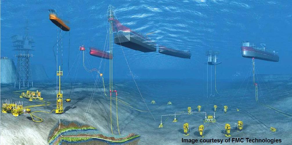
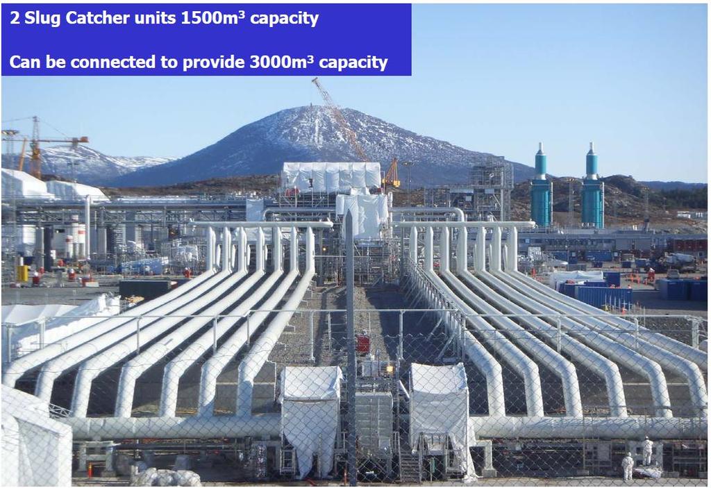
40 Gas condensate flowline slug catcher Ormen Lange
41
42
PETROLEUM & GAS PROCESSING TECHNOLOGY (PTT 365) SEPARATION OF PRODUCED FLUID
 SEPARATION OF PRODUCED FLUID") PETROLEUM & GAS PROCESSING TECHNOLOGY (PTT 365) SEPARATION OF PRODUCED FLUID Miss Nur Izzati Bte Iberahim Introduction Well effluents flowing from producing wells come out in two phases: vapor and liquid
PETROLEUM & GAS PROCESSING TECHNOLOGY (PTT 365) SEPARATION OF PRODUCED FLUID Miss Nur Izzati Bte Iberahim Introduction Well effluents flowing from producing wells come out in two phases: vapor and liquid
Vortex Separation Technologies. Engineered Solutions to Separation Problems
 Vortex Separation Technologies Engineered Solutions to Separation Problems Vortex Technology Internals use the high-energy momentum of fluids to produce a high G force which sends the liquids and solids
OIL AND GAS SEPARATION DESIGN MANUAL
 OIL AND GAS SEPARATION DESIGN MANUAL BY C. RICHARD SIVALLS, P.E. SIVALLS, INC. BOX 2792 ODESSA, TEXAS 79760 All rights reserved. This publication is fully protected by copyright and nothing that appears
Air Eliminators and Combination Air Eliminators Strainers
 Description Air Eliminators and Combination Air Eliminator Strainers are designed to provide separation, elimination and prevention of air in piping systems for a variety of installations and conditions.
OLGA. The Dynamic Three Phase Flow Simulator. Input. Output. Mass transfer Momentum transfer Energy transfer. 9 Conservation equations
 서유택 Flow Assurance The Dynamic Three Phase Flow Simulator 9 Conservation equations Mass (5) Momentum (3) Energy (1) Mass transfer Momentum transfer Energy transfer Input Boundary and initial conditions
INNOVATIVE GAS-LIQUID SEPARATOR INCREASES GAS PRODUCTION IN THE NORTH SEA
 INNOVATIVE GAS-LIQUID SEPARATOR INCREASES GAS PRODUCTION IN THE NORTH SEA Roy Viteri Sulzer Chemtech USA, Inc. 4106 New West Drive Pasadena, TX 77507 (281) 604-4119 Roy.viteri@sulzer.com Daniel Egger Sulzer
PRODUCTION EQUIPMENT EFFECTS ON ORIFICE MEASUREMENT STORMY PHILLIPS J-W MEASUREMENT 9726 E. 42 ND STREET, STE. 229 TULSA, OK 74146
 PRODUCTION EQUIPMENT EFFECTS ON ORIFICE MEASUREMENT Purpose STORMY PHILLIPS J-W MEASUREMENT 9726 E. 42 ND STREET, STE. 229 TULSA, OK 74146 This paper is designed to serve as an update to the paper formally
PRODUCTION EQUIPMENT EFFECTS ON ORIFICE MEASUREMENT. Stormy Phillips
 PRODUCTION EQUIPMENT EFFECTS ON ORIFICE MEASUREMENT Introduction Stormy Phillips Product Manager Legacy Measurement Solutions 9726 East 42nd Street Suite 219 Tulsa, OK 74126 The condition of gas as it
Knowledge, Certification, and Networking
 www.iacpe.com Knowledge, Certification, and Networking Page: 1 of 101 Rev 01 IACPE No 19, Jalan Bilal Mahmood 80100 Johor Bahru Malaysia Separator Vessel Selection and Sizing CPE LEVEL TWO TRAINING MODULE
At the end of this lesson, you will be able to do the following:
 Liquid-Phase Contacting Scrubbers Goal To familiarize you with the operation, collection efficiency, and major maintenance problems of liquid-phase contacting scrubbers. Objectives At the end of this lesson,
Offshore Equipment. Yutaek Seo
 Offshore Equipment Yutaek Seo Flash Gas Compressor (East spar) Dehydration NGL recovery Slug catcher Separator Stabilization Booster compressor Gas export compression (Donghae-1 Platform) May 7 th Gas
Solutions, Standards and Software. SEPARATOR VESSELS SIZING AND SELECTION (ENGINEERING DESIGN GUIDELINE)
") Page : 1 of 71 for Processing Plant Solutions KLM Technology #03-12 Block Aronia, Jalan Sri Perkasa 2 Taman Tampoi Utama 81200 Johor Bahru Malaysia Solutions, Standards and Software www.klmtechgroup.com
Page : 1 of 71 for Processing Plant Solutions KLM Technology #03-12 Block Aronia, Jalan Sri Perkasa 2 Taman Tampoi Utama 81200 Johor Bahru Malaysia Solutions, Standards and Software www.klmtechgroup.com
Natural Gas Conditioning Skids & Equipments
 Natural Gas Conditioning Skids & Equipments NATURAL GAS CONDITIONING SKIDS NIRMAL has rich experience of supplying complete package of Natural Gas conditioning skids consisting of emergency shut down,
The Discussion of this exercise covers the following points:
 Exercise 3-2 Orifice Plates EXERCISE OBJECTIVE In this exercise, you will study how differential pressure flowmeters operate. You will describe the relationship between the flow rate and the pressure drop
White Paper. Electrical control valve actuators on oil and gas production separators
 White Paper Electrical control valve actuators on oil and gas production separators Electrical control valve actuators on oil and gas production separators White Paper 18 th August 2014 Electrical control
Caltec. The world leader in Surface Jet Pump (SJP) and compact separation systems for upstream oil and gas production enhancement
 and compact separation systems for upstream oil and gas production enhancement") Caltec brings simple passive technology that enables oil and gas operators to harness the kinetic energy of the production process to enhance their production, extending economic field life and reducing
Caltec brings simple passive technology that enables oil and gas operators to harness the kinetic energy of the production process to enhance their production, extending economic field life and reducing
Peerless TECH SPEC FOR HIGH-EFFICIENCY, HIGH-CAPACITY, AND LOW-COST GAS AND LIQUID SEPARATION
 Peerless TEH SPE Vane SEPRTORS See what Peerless can do for you. FOR HIGH-EFFIIENY, HIGH-PITY, ND LOW-OST GS ND LIQUID SEPRTION HORIZONTL SEPRTOR For handling high liquid rates and large slugs. VERTIL
In this third article of a three-part series, the results of
 Gas/Liquids Separators Part 3 Quantifying Separation Performance Mark Bothamley, John M. Campbell/PetroSkills In this third article of a three-part series, the results of selected gas/liquid separation
Gas Lift Workshop Doha Qatar 4-88 February Gas Lift Optimisation of Long Horizontal Wells. by Juan Carlos Mantecon
 Gas Lift Workshop Doha Qatar 4-88 February 2007 Gas Lift Optimisation of Long Horizontal Wells by Juan Carlos Mantecon 1 Long Horizontal Wells The flow behavior of long horizontal wells is similar to pipelines
LAKOS Waterworks. PWC Series Sand Separators. Installation & Operation Manual LS-829 (10/12)
") LAKOS Waterworks PWC Series Sand Separators Installation & Operation Manual LS-829 (10/12) Table of Contents Separator Operation... 3 Individual Model Details.... 4 Flow vs. Pressure Loss Chart 4 Installation
LAKOS Waterworks PWC Series Sand Separators Installation & Operation Manual LS-829 (10/12) Table of Contents Separator Operation... 3 Individual Model Details.... 4 Flow vs. Pressure Loss Chart 4 Installation
THE INNER WORKINGS OF A SIPHON Jacques Chaurette p. eng. January 2003
 THE INNER WORKINGS OF A SIPHON Jacques Chaurette p. eng. www.lightmypump.com January 2003 Synopsis The objective of this article is to explain how a siphon works. The difference between low pressure, atmospheric
making energy safe, efficient and clean FOR HIGH-EFFICIENCY, HIGH-CAPACITY, COST EFFECTIVE GAS AND LIQUID SEPARATION HORIZONTAL SEPARATOR
 FOR HIGH-EFFIIENY, HIGH-PITY, OST EFFETIVE GS ND LIQUID SEPRTION HORIZONTL SEPRTOR For handling high liquid rates and large slugs VERTIL SEPRTOR For slug removal applications and small footprint installations
Fundamentals Of Petroleum Engineering PRODUCTION
 Fundamentals Of Petroleum Engineering PRODUCTION Mohd Fauzi Hamid Wan Rosli Wan Sulaiman Department of Petroleum Engineering Faculty of Petroleum & Renewable Engineering Universiti Technologi Malaysia
Slug Catchers Engineered Solutions to Separation Problems
 Slug Catchers Engineered Solutions to Separation Problems Separation Products from Taylor Forge Taylor Forge Engineered Systems has been a leading manufacturer of liquid separation equipment for the pipeline
Two Phase Fluid Flow (ENGINEERING DESIGN GUIDELINE)
") Page : 1 of 61 Rev: 01 Guidelines for Processing Plant www.klmtechgroup.com Rev 01 KLM Technology #03-12 Block Aronia, Jalan Sri Perkasa 2 Taman Tampoi Utama 81200 Johor Bahru (ENGINEERING DESIGN GUIDELINE)
Page : 1 of 61 Rev: 01 Guidelines for Processing Plant www.klmtechgroup.com Rev 01 KLM Technology #03-12 Block Aronia, Jalan Sri Perkasa 2 Taman Tampoi Utama 81200 Johor Bahru (ENGINEERING DESIGN GUIDELINE)
DUAL-VORTEX SEPARATOR. Inspection and Maintenance Guide
 DUAL-VORTEX SEPARATOR Inspection and Maintenance Guide Description The Dual-Vortex Separator (DVS) is a hydrodynamic stormwater treatment device used to remove pollutants from urban runoff. Impervious
Pigging as a Flow Assurance Solution Avoiding Slug Catcher Overflow
 Pigging as a Flow Assurance Solution Avoiding Slug Catcher Overflow Aidan O'Donoghue, Pipeline Research Limited, Glasgow, UK This paper sets out to provide an initial method of assessing the bypass requirements
CPE562 Chemical Process Control HOMEWORK #1 PROCESS & INSTRUMENTATION DIAGRAM
 Faculty of Chemical Engineering CPE562 Chemical Process Control HOMEWORK #1 PROCESS & INSTRUMENTATION DIAGRAM SUBMISSION DATE: 1 OCT. 2012 Question 1 Name the following equipments based on standard P&ID
SHOP WELDED TANKS STANDARD CONNECTIONS
 STEEL WELDED TANKS Tanks are constructed using 3/16 and ¼ inch A36 material. Welding and testing are performed according to API 12F specifications. Shop welded tanks are also available in special sizes
This portion of the piping tutorial covers control valve sizing, control valves, and the use of nodes.
 Piping Tutorial A piping network represents the flow of fluids through several pieces of equipment. If sufficient variables (flow rate and pressure) are specified on the piping network, CHEMCAD calculates
Bioreactor System ERT 314. Sidang /2011
 Bioreactor System ERT 314 Sidang 1 2010/2011 Chapter 2:Types of Bioreactors Week 4 Flow Patterns in Agitated Tanks The flow pattern in an agitated tank depends on the impeller design, the properties of
Application of CFD for Improved Vertical Column Induced Gas Flotation (IGF) System Development
 System Development") Application of CFD for Improved Vertical Column Induced Gas Flotation (IGF) System Development Chang-Ming Lee and Ted Frankiewicz NATCO Group, Inc., 2950 North Loop West, Suite 750, Houston, TX 77092 Prepared
Application of CFD for Improved Vertical Column Induced Gas Flotation (IGF) System Development Chang-Ming Lee and Ted Frankiewicz NATCO Group, Inc., 2950 North Loop West, Suite 750, Houston, TX 77092 Prepared
EDUCTOR. principle of operation
 EDUCTOR principle of operation condensate and mixing eductor s are designed to mix two liquids intimately in various proportions in operations where the pressure liquid is the greater proportion of the
From the Choke KO drum, the gas passes through another gas/gas exchanger - the 'LTS Pre-cooler'.
 Refer to Figures: 16 & 17 as you read on. Wet, natural gas direct from the wellstreams, at about 1600 Psi, is first pre-cooled and separated from liquids in an 'Intermediate Separator' and cooled in a
Generating Calibration Gas Standards
 Technical Note 1001 Metronics Inc. Generating Calibration Gas Standards with Dynacal Permeation Devices Permeation devices provide an excellent method of producing known gas concentrations in the PPM and
Application Worksheet
 Application Worksheet All dimensions are nominal. Dimensions in [ ] are in millimeters. Service Conditions Medium Through Valve: Required C v : Temperature Maximum: Minimum: Normal: Flow Maximum: Minimum:
Level MEASUREMENT 1/2016
 Level MEASUREMENT 1/2016 AGENDA 2 A. Introduction B. Float method C. Displacer method D. Hydrostatic pressure method E. Capacitance method G. Ultrasonic method H. Radar method I. Laser method J. Level
API th Edition Ballot Item 7.8 Work Item 4 Gas Breakthrough
 API 521 7 th Edition Ballot Item 7.8 Work Item 4 Gas Breakthrough NOTE: This is a reballot of previously approved API 521 7 th Edition Ballot Item 6.3 which was modified based on comments. Comments should
Irrigation &Hydraulics Department lb / ft to kg/lit.
 CAIRO UNIVERSITY FLUID MECHANICS Faculty of Engineering nd Year CIVIL ENG. Irrigation &Hydraulics Department 010-011 1. FLUID PROPERTIES 1. Identify the dimensions and units for the following engineering
Tube rupture in a natural gas heater
 Tube rupture in a natural gas heater Dynamic simulation supports the use of a pressure safety valve over a rupture disk in the event of a tube rupture HARRY Z HA and PATRICK STANG Fluor Canada Ltd A fast
Digester Processes. 1. Raw Sludge Pumping System
 Digester Processes 1. Raw Sludge Pumping System Removes accumulated sludge from the primary clarifiers, pumped through 1 of 2 pipes either 150 or 200mm in diameter (Fig. 1.1). Fig 1.1 Pipes feeding Digesters
Installation Operation Maintenance
 682 Seal Cooler New generation seal cooler to meet and exceed the seal cooler requirements stated in the 4th Edition of API Standard 682 Installation Operation Maintenance Experience In Motion Description
TECHNICAL DATA. Q = C v P S
 Page 1 of 13 1. DESCRIPTION The Viking 6 Model G-6000 Dry Valve Riser Assembly consists of a small profile, light weight, pilot operated valve that is used to separate the water supply from the dry sprinkler
The Discussion of this exercise covers the following points: Pumps Basic operation of a liquid pump Types of liquid pumps The centrifugal pump.
 Exercise 2-3 Centrifugal Pumps EXERCISE OBJECTIVE In this exercise, you will become familiar with the operation of a centrifugal pump and read its performance chart. You will also observe the effect that
TROUBLESHOOTING GUIDELINES
 TROUBLESHOOTING GUIDELINES PROBLEM: Performance 1. The most common problem in this area comes from inadequate flow to the LAKOS Separator(s). All LAKOS Separators operate within a prescribed flow range
OTC Copyright 2001, Offshore Technology Conference
 OTC 13215 Reducing Separation Train Sizes and Increasing Capacity by Application of Emerging Technologies Ted Frankiewicz/NATCO GROUP, Michael M. Browne/ NATCO GROUP, Chang-Ming Lee/NATCO GROUP Copyright
Pneumatic Conveying Systems Theory and Principles Session 100
 Pneumatic Conveying Systems Theory and Principles Session 100 1 Controls & Instrumentation P = Actual Pressure V = Actual Volume T is Typically Ignored Key Relationship PV/T Terminal Point Any Point Pick
Vapor Recovery from Condensate Storage Tanks Using Gas Ejector Technology Palash K. Saha 1 and Mahbubur Rahman 2
 37 Journal of Chemical Engineering, IEB Vapor Recovery from Condensate Storage Tanks Using Gas Ejector Technology Palash K. Saha 1 and Mahbubur Rahman 2 Abstract 1 Bibyana Gas Field 2 Department of Petroleum
Design a grit chamber for population with water consumption of 135 LPCD.
 1 Example:1 Design a grit chamber for population 50000 with water consumption of 135 LPCD. Solution Average quantity of sewage, considering sewage generation 80% of water supply, is = 135 x 50000 x 0.8
PTRT 2470: Petroleum Data Management 3 - Facilities Test 4 (Spring 2017)
") Use scantron to answer all questions PTRT 2470: Petroleum Data Management 3 - Facilities Test 4 (Spring 2017) 1. The term dehydration of natural gas means A. addition of water vapor B. removal of water
Use scantron to answer all questions PTRT 2470: Petroleum Data Management 3 - Facilities Test 4 (Spring 2017) 1. The term dehydration of natural gas means A. addition of water vapor B. removal of water
Permeability. Darcy's Law
 Permeability Permeability is a property of the porous medium that measures the capacity and ability of the formation to transmit fluids. The rock permeability, k, is a very important rock property because
SFC. SKYLINE FLOW CONTROLS INC. The Leader of Accurate and Reliable Flow Measurement DESCRIPTION & APPLICATIONS: ADVANTAGES:
 SKYLINE FLOW CONTROLS INC. SFC Skyline Flow Controls Wedge Meter (SFC-WM) The SFC wedge meter is a differential pressure device for use on all fluids. It is especially designed for slurries and liquids
Simplicity in VRU by using a Beam Gas Compressor
 Simplicity in VRU by using a Beam Gas Compressor By Charlie D. McCoy and Mark Lancaster Abstract: Vapor Recovery Units are often expensive, complicated to operate and unable to deal with High H2S and liquids.
Computer Simulation Helps Improve Vertical Column Induced Gas Flotation (IGF) System
 System") JOURNAL ARTICLES BY FLUENT SOFTWARE USERS JA187 Computer Simulation Helps Improve Vertical Column Induced Gas Flotation (IGF) System Computer simulation has helped NATCO engineers make dramatic improvements
JOURNAL ARTICLES BY FLUENT SOFTWARE USERS JA187 Computer Simulation Helps Improve Vertical Column Induced Gas Flotation (IGF) System Computer simulation has helped NATCO engineers make dramatic improvements
Operating Guidelines for PermSelect Modules Liquid Contacting
 Operating Guidelines for PermSelect Modules Liquid Contacting PermSelect PDMSXA-2500 (0.25m 2 ) PermSelect PDMSXA-7500 (0.75m 2 ) PermSelect PDMSXA-1.0 (1m 2 ) PermSelect PDMSXA-2.1 (2.1m 2 ) PermSelect
Facilities Design Shift Horizontal Equipment in Oklahoma Scott King
 Facilities Design Shift Horizontal Equipment in Oklahoma Scott King Facilities Review in Oklahoma Identified areas for improvement Design criteria is outdated for play types Vertical separation, cannot
CVEN 311 Fluid Dynamics Fall Semester 2011 Dr. Kelly Brumbelow, Texas A&M University. Final Exam
 CVEN 311 Fluid Dynamics Fall Semester 2011 Dr. Kelly Brumbelow, Texas A&M University Final Exam 8 pages, front & back, not including reference sheets; 21 questions An excerpt from the NCEES Fundamentals
. In an elevator accelerating upward (A) both the elevator accelerating upward (B) the first is equations are valid
 both the elevator accelerating upward (B) the first is equations are valid") IIT JEE Achiever 2014 Ist Year Physics-2: Worksheet-1 Date: 2014-06-26 Hydrostatics 1. A liquid can easily change its shape but a solid cannot because (A) the density of a liquid is smaller than that of
IIT JEE Achiever 2014 Ist Year Physics-2: Worksheet-1 Date: 2014-06-26 Hydrostatics 1. A liquid can easily change its shape but a solid cannot because (A) the density of a liquid is smaller than that of
The Discussion of this exercise covers the following points:
 Exercise 5-3 Wet Reference Leg EXERCISE OBJECTIVE Learn to measure the level in a vessel using a wet reference leg. DISCUSSION OUTLINE The Discussion of this exercise covers the following points: Measuring
Applied Fluid Mechanics
 Applied Fluid Mechanics 1. The Nature of Fluid and the Study of Fluid Mechanics 2. Viscosity of Fluid 3. Pressure Measurement 4. Forces Due to Static Fluid 5. Buoyancy and Stability 6. Flow of Fluid and
"INOGATE Technical Secretariat & Integrated Programme in support of the Baku Initiative and the Eastern Partnership energy objectives" Project
 "INOGATE Technical Secretariat & Integrated Programme in support of the Baku Initiative and the Eastern Partnership energy objectives" Project B U I L D I N G P A R T N E R S H I P S F O R E N E R G Y
SPECIFYING MOTIONLESS MIXERS
 SPECIFYING MOTIONLESS MIXERS The operating cost for the energy necessary to mix fluids with a motionless mixer is usually far lower than for any competitive mixing technique. An extruder which melts, mixes
Restriction Orifice. Single or Multi Stage Orifice to. Reduce Pressure or. Limit the Flow Rate
 Restriction Orifice Single or Multi Stage Orifice to Reduce Pressure or Limit the Flow Rate Restriction Orifice Plates Series ROPS Principle Restriction Orifice Plates and Critical Flow Devices and their
Instrumentation & Data Acquisition Systems
 Instrumentation & Data Acquisition Systems Section 3 -Level Robert W. Harrison, PE Bob@TheHarrisonHouse.com Made in USA 1 Level Section Question Which level measuring technology is the best solution when
COMPRESSED AIR DISTRIBUTION SYSTEMS
 Series COMPRESSED AIR DISTRIBUTION SYSTEMS 18 DESIGNING AN EFFICIENT COMPRESSED AIR DISTRIBUTION The main source of inefficiencies and problems affecting compressed air distribution systems is often the
Vacuum Systems and Cryogenics for Integrated Circuit Fabrication Technology 01
 INAOE. Tonantzintla, Mexico. 2010-06-23. June 23 rd, 2010 Vacuum Systems and Cryogenics for Integrated Circuit Fabrication Technology 01 Joel Molina INAOE Microelectronics Group jmolina@inaoep.mx 1 Vacuum
PROCESS GAS SAMPLING SYSTEMS
 1 PROCESS GAS SAMPLING SYSTEMS Engineered Solutions 2 Sample conditioning system System functions How it works Key components Design and layout Pre-conditioning components Custom solutions System functions
Energy Specialties International
 Company Information Company: Address: Engineer: Phone: Fax: E-mail: Skim Pile Information Deck Area: Water Depth: Rainfall Intensity: Cellar Deck El.: Boat Deck El.: Continuous or Intermittent Flow: Oil
Module 15 : Grit Chamber. Lecture 20 : Grit Chamber
 1 P age Module 15 : Grit Chamber Lecture 20 : Grit Chamber 2 P age 15.6 Square Grit Chamber The horizontal flow rectangular grit chamber faces the problem of sedimentation of organic matter along with
Pumping Systems for Landscaping Pumps, Controls and Accessories. Mark Snyder, PE
 October 21, 2010 Pumping Systems for Landscaping Pumps, Controls and Accessories Mark Snyder, PE Pump Station Design Purpose of Pump Stations Pump stations are designed to boost water pressure from a lower
Exercise 4-2. Centrifugal Pumps EXERCISE OBJECTIVE DISCUSSION OUTLINE DISCUSSION. Pumps
 Exercise 4-2 Centrifugal Pumps EXERCISE OBJECTIVE Familiarize yourself with the basics of liquid pumps, specifically with the basics of centrifugal pumps. DISCUSSION OUTLINE The Discussion of this exercise
PHYS 101 Previous Exam Problems
 PHYS 101 Previous Exam Problems CHAPTER 14 Fluids Fluids at rest pressure vs. depth Pascal s principle Archimedes s principle Buoynat forces Fluids in motion: Continuity & Bernoulli equations 1. How deep
PRODUCTION AND OPERATIONAL ISSUES
 PRODUCTION AND OPERATIONAL ISSUES Dr. Ebrahim Fathi Petroleum and Natural Gas Engineering Department West Virginia University Audience and Date March 2, 2016 Summary Production and Operational Issues Shale
DEVELOPING RATIONAL CRITERIA FOR GAS/OIL/WATER/SAND SEPARATION METHODS
 DEVELOPING RATIONAL CRITERIA FOR GAS/OIL/WATER/SAND SEPARATION METHODS By MAMUDU ANGELA, B. Eng. Chemical Engineering. A dissertation submitted in partial fulfilment of the requirements of the award of
SB AXIAL FLOW VALVES
 SB9509.3 AXIAL FLOW VALVES The improved technology for pressure regulation The American Axial Flow Valve provides pressure and flow control in high capacity pipelines. It can be used for pressure regulation,
Installation and operation Manual. Bermad Surge Anticipation Valve. Model No 435
 Instruction manual Bermad surge anticipation manual Model No 435 Installation and operation Manual Bermad Surge Anticipation Valve Model No 435 Bermad Water Technologies Rev 0 5/05/2015 7 Inglewood Drive,
Suppress Your Surges: Surge Suppression Fundamentals. April 13, 2017
 Suppress Your Surges: Surge Suppression Fundamentals April 13, 2017 How Bad Can Waterhammer Really Be? 2 Workshop Agenda What is waterhammer? Causes of waterhammer Instantaneous surge pressures Surges
ENSURING AN ACCURATE RESULT IN AN ANALYTICAL INSTRUMENTATION SYSTEM PART 1: UNDERSTANDING AND MEASURING TIME DELAY
 ENSURING AN ACCURATE RESULT IN AN ANALYTICAL INSTRUMENTATION SYSTEM PART 1: UNDERSTANDING AND MEASURING TIME DELAY Process measurements are instantaneous, but analyzer responses never are. From the tap
TECHNICAL DATA. Q = C v P S
 January 6, 2012 Preaction 348a 1. Description Viking supervised Surefire Preaction Systems utilize the Viking G-6000P Valve. The small profile, lightweight, pilot operated Viking G-6000P Valve comes complete
TECHNICAL DATA. Q = C v P S
 January 6, 2012 Preaction 333a 1. Description Viking supervised Surefire Preaction Systems Utilize the Viking G-3000P Valve. The small profile, lightweight, pilot-operated Viking G-3000P Valve comes complete
DAV - P. Product Catalogue DAV - P. Air release & Vacuum Break Valves. (Plastic Air Valves) DAV - P. Edition 2012
 DAV - P. Edition 2012") Product Catalogue DAV - P DAV - P Air release & Vacuum Break Valves Edition 1 DAV - P (Plastic Air Valves) DAV Series Overview General The presence of trapped air in a pressurized pipeline can have serious
Product Catalogue DAV - P DAV - P Air release & Vacuum Break Valves Edition 1 DAV - P (Plastic Air Valves) DAV Series Overview General The presence of trapped air in a pressurized pipeline can have serious
A centrifugal pump consists of an impeller attached to and rotating with the shaft and a casing that encloses the impeller.
 Centrifugal pump How centrifugal pumps work A centrifugal pump consists of an impeller attached to and rotating with the shaft and a casing that encloses the impeller. In centrifugal pump, liquid is forced
COMPARING PLUG & SEAT REGULATORS & CONTROL VALVES. Lamar Jones. Equipment Controls Company 4555 South Berkeley Lake Road Norcross, GA 30071
 COMPARING PLUG & SEAT REGULATORS & CONTROL VALVES Lamar Jones Equipment Controls Company 4555 South Berkeley Lake Road Norcross, GA 30071 INTRODUCTION The purpose of this paper will be to compare a plug
Structure of Mechanically Agitated Gas-Liquid Contactors
 Structure of Mechanically Agitated Gas-Liquid Contactors 5 2 Structure of Mechanically Agitated Gas-Liquid Contactors 2.1 The vessel geometry The most commonly adopted geometry of a stirred gas-liquid
TECHNIQUES OF COMPOSITE SAMPLING. Kris Kimmel. YZ Systems, Inc Pollok Drive Conroe, Texas 77303
 TECHNIQUES OF COMPOSITE SAMPLING Kris Kimmel YZ Systems, Inc. 3101 Pollok Drive Conroe, Texas 77303 Introduction Since a gas sampling system can be referred to as a cash register it is very important that
Gas Injection for Hydrodynamic Slug Control
 Proceedings of the IFAC Workshop on Automatic Control in Offshore Oil and Gas Production, Norwegian University of Science and Technology, Trondheim, Norway, May 3 - June, ThB.4 Gas Injection for Hydrodynamic
DB Bridge Plug. Features. Benefits. Applications
 DB Bridge Plug The WELLFIRST Premium Cast Iron Bridge Plug designed to run on electric line. Rated between 2000-10000-psi differential, and 300 F from above and below. Features Field Proven Design Constructed
TECHNICAL DATA. Q= Cv S
 Page 1 of 13 1. DESCRIPTION The Viking 4 inch Model G-4000 Dry Valve Riser Assembly consists of a small profile, light weight, pilot operated valve that is used to separate the water supply from the dry
2 Sentry MCL Installation, Operation & Maintenance
 Gas Liquid & Slurry Solid & Powder Steam & Water Installation, Operation & Maintenance Manual Original Instructions Liquid Sampling Manual Low-Emission Samplers S-GA-IOM-00249-7 11-17 Sentry MCL 966 Blue
ACCURACY, PERFORMANCE, AND HANDLING OF OIL-FILLED DIGIQUARTZ PRESSURE INSTRUMENTATION
 Application Note Doc. G8108-001 Rev. A - 23-Jul-02 ACCURACY, PERFORMANCE, AND HANDLING OF OIL-FILLED DIGIQUARTZ PRESSURE INSTRUMENTATION For more information regarding Digiquartz products contact: Paroscientific,
Dean Pump Self-Priming Chemical Process Pumps
 Bulletin C 1.2.34.7 Dean Pump Self-Priming Chemical Process Pumps php Series HEAD CAPACITY RANGE CHARTS php Self Primer - 2 Pole 3500 RPM 500 CAPACITY M 3 /HR 2900 RPM 50 HERTZ 25 50 75 125 150 400 TOTAL
Numerical Simulations of a Train of Air Bubbles Rising Through Stagnant Water
 Numerical Simulations of a Train of Air Bubbles Rising Through Stagnant Water Hong Xu, Chokri Guetari ANSYS INC. Abstract Transient numerical simulations of the rise of a train of gas bubbles in a liquid
ISS0065 Control Instrumentation Lecture 12
 ISS0065 Control Instrumentation Lecture 12 1 Flow measurement Flow, defined as volume per unit of time at specified temperature and pressure conditions. The principal classes of flow-measuring instruments
Static Fluids. **All simulations and videos required for this package can be found on my website, here:
 DP Physics HL Static Fluids **All simulations and videos required for this package can be found on my website, here: http://ismackinsey.weebly.com/fluids-hl.html Fluids are substances that can flow, so
TABLE OF CONTENT
 Page : 1 of 22 Project Engineering Standard www.klmtechgroup.com KLM Technology #03-12 Block Aronia, Jalan Sri Perkasa 2 Taman Tampoi Utama 81200 Johor Bahru Malaysia S) TABLE OF CONTENT SCOPE 2 VESSELS
Radar, Ultrasonic and RF Level Transmitters
 Radar, Ultrasonic and RF Level Transmitters Both measures the time it takes the wave to travel between the transmitter and that reflected wave off the surface of the material to reach the transmitter again.
TECHNICAL DATA 3 MODEL G-3000 DRY VALVE RISER ASSEMBLY
 Page 1 of 13 1. DESCRIPTION The Viking 3 Model G-3000 Dry Valve Riser Assembly is equipped with a small profile, light weight, pilot operated valve that is used to separate the water supply from the dry
3. A fluid is forced through a pipe of changing cross section as shown. In which section would the pressure of the fluid be a minimum?
 AP Physics Multiple Choice Practice Fluid Mechanics 1. A cork has weight mg and density 5% of water s density. A string is tied around the cork and attached to the bottom of a water-filled container. The
CTB3365x Introduction to Water Treatment
 CTB3365x Introduction to Water Treatment D4b Aeration Doris van Halem Did you know that there are not just gasses in your glass of sparkling coke, but also in the tap water you drink? Welcome to the water
Reduce Turnaround Duration by Eliminating H 2 S from Flare Gas Utilizing VaporLock Scrubber Technology
 Reduce Turnaround Duration by Eliminating H 2 S from Flare Gas Utilizing VaporLock Scrubber Technology Jim Woodard Vice President of Sales Bryant Woods Lead Project Engineer 4/3/18 Page 1 Objectives Impact