GPR-2800 IS Oxygen Transmitter
|
|
|
- Mary Malone
- 5 years ago
- Views:
Transcription
 gas streams Certified for use in hazardous areas - see lower right UL: United")


1 Technical Specifications * Accuracy: < 2% of FS range under constant conditions UL or ATEX Certified for Hazardous Areas Analysis: Application: Approvals: 0-1%, 0-5%, 0-10%, 0-25% FS ranges; auto-ranging or fixed single range Oxygen analysis in inert, hydrocarbon, helium, hydrogen, mixed and acid (CO 2 ) gas streams Certified for use in hazardous areas - see lower right UL: United States: UL 1203, UL 913, UL 508 Canada: CAN/CSA C22.2 No. 30-M1986, CAN/CSA C22.2 No , CAN/CSA C22.2 No ATEX: Directive 94/9/EC Area Classification: Certified for use in hazardous areas - see lower right Calibration: Compensation: Connections: Controls: Max interval 3 months. Air calibrate with clean source of certified span gas, compressed, or ambient (20.9% O2) air on 0-25% range. Temperature 1/8" compression tube fittings Water resistant keypad; menu driven range selection, calibration and system functions Display: Graphical LCD 2.75 x ; resolution 0.001%; displays real time ambient temperature and pressure Enclosure: NEMA Type 3R for rain in outdoor applications (UL) NEMA 4X (ATEX) GPR-2800 IS Oxygen Transmitter Loop Powered O2 Transmitter Optional Modular Sample Systems Flow: Linearity: Pressure: Power: Response Time: Sample System: Sensitivity: Sensor Model: Sensor Life: Signal Output: Operating Range: Warranty: Wetted Parts: Not flow sensitive; recommended flow rate 1-2 SCFH ±1% of full scale Inlet - regulate to 5-30 psig to deliver 1-2 SCFH flow; vent - atmospheric VDC 90% of final reading in 10 seconds Sample flow meter; options available, see other side < 0.5% of FS range GPR for non-acid (CO2) gas streams XLT for gases containing > 0.5% CO2 GPR months in air at 25 C and 1 atm XLT months in air at 25 C and 1 atm 4-20mA 5ºC to 45ºC (GPR sensor); -10º to 45ºC (XLT) 12 months analyzer; 12 months sensor Stainless steel Exia UL Certified File E Class I, Division 1, Groups C and D T4 T amb -20⁰C to +50⁰C ATEX Certified - Directive 94/9/EC Examination Cert: INERIS 08ATEX0036 II 2 G Ex d [ib] ib IIB T4 T amb -20⁰C to +50⁰C 0080 Optional Equipment Sample conditioning systems (see back page) - Contact factory ISO 9001:2008 Certified INTERTEK Certificate No. 485 * Specifications subject to change without notice 2855 Metropolitan Place, Pomona, CA USA Tel: , Fax: , info@aii1.com Rev 10/15


2 Advanced Instruments Inc. GPR-2800 IS PPM Oxygen Transmitter Shown with Optional A Sample System Owner s Manual 2855 Metropolitan Place, Pomona, California USA Tel: , Fax: , e- mail: info@aii1.com
3 Table of Contents Introduction 1 Quality Control Certification 2 Safety 3 Features & Specifications 4 Operation 5 Maintenance 6 Spare Parts 7 Troubleshooting 8 Warranty 9 Material Safety Data Sheets 10 Drawings A/R Explosion Proofing Electrical Connections Appendix A Correlating readings LCD display to 4-20mA signal Appendix B output H2S Scrubber, Sample System, Media MSDS Appendix F Maintenance H2S Scrubber & Coalescing Filter Appendix G The appendices referenced above are an integral part of the documentation, installation and maintenance of this analyzer to comply with all applicable directives. It is important that users review these documents before proceeding. 2
4 1. Introduction Your new oxygen transmitter incorporates an advanced electrochemical sensor specific to oxygen along with state-of-the-art digital electronics designed to give you years of reliable precise oxygen measurements in a variety of industrial oxygen applications. More importantly, it has been constructed as intrinsically safe in accordance with ATEX Directives 94/9/EC for use in hazardous areas in zone 1 Group C and D. T h e d e s i g n a l s o m e e t s Analytical Industries Inc. dba Advanced Instruments Inc Metropolitan Place, Pomona, CA USA GPR-1800IS/2800IS 0080 Serial No.: Year of Manufacture: INERIS 08ATEX0036 II 2 G Ex d [ib] ib IIB T4 T amb -20⁰C to +50⁰C WARNING: POTENTIAL ELECTROSTATIC CHARGING HAZARD SEE INSTRUCTIONS The transmitter also complies with NEC intrinsic safety standards for use in Class 1, Division 1, Group C, D hazardous areas. Please refer to Appendix A for information on making electrical connections that maintain the desired level of protection. To obtain maximum performance from your new oxygen transmitter, please read and follow the guidelines provided in this Owner s Manual. Every effort has been made to select the most reliable state of the art materials and components, to design the transmitter for superior performance and minimal cost of ownership. This transmitter was tested thoroughly by the manufacturer prior to shipment for best performance. However, modern electronic devices do require service from time to time. The warranty included herein plus a staff of trained professional technicians to quickly service your transmitter is your assurance that we stand behind every transmitter sold. The serial number of this transmitter may be found on the inside the transmitter enclosure. You should note the serial number in the space provided and retains this Owner s Manual as a permanent record of your purchase, for future reference and for warranty considerations. Serial Number: Advanced Instruments Inc. appreciates your business and pledges to make every effort to maintain the highest possible quality standards with respect to product design, manufacturing and service. 3
5 3. General Safety & Installation This section summarizes the essential precautions applicable to the GPR-2800IS Oxygen Transmitter. Additional precautions specific to individual transmitter are contained in the following sections of this manual. To operate the transmitter safely and obtain maximum performance follow the basic guidelines outlined in this Owner s Manual. Caution: This symbol is used throughout the Owner s Manual to Caution and alert the user to recommended safety and/or operating guidelines. Warning: This symbol is used throughout the Owner s Manual to Warn and alert the user of the presence of electrostatic discharge. Danger: This symbol is used throughout the Owner s Manual to identify sources of immediate Danger such as the presence of hazardous voltages. Read Instructions: Before operating the transmitter read the instructions. Retain Instructions: The safety precautions and operating instructions found in the Owner s Manual should be retained for future reference. Heed Warnings: Follow all warnings on the transmitter, accessories (if any) and in this Owner s Manual. Follow Instructions: Observe all precautions and operating instructions. Failure to do so may result in personal injury or damage to the transmitter. Analyzer label 4
6 2. Quality Control Certification 5
7 Maintenance Serviceability: Except for replacing the oxygen sensor, there are no parts inside the transmitter for the operator to service. Only trained personnel with the authorization of their supervisor should conduct maintenance. Oxygen Sensor: DO NOT open the sensor. The sensor contains a corrosive liquid electrolyte that could be harmful if touched or ingested, refer to the Material Safety Data Sheet contained in the Owner s Manual appendix. Avoid contact with any liquid or crystal type powder in or around the sensor or sensor housing, as either could be a form of electrolyte. Leaking sensors should be disposed of in accordance with local regulations. Troubleshooting: Consult the guidelines in Section 8 for advice on the common operating errors before concluding that your transmitter is faulty. Do not attempt to service the transmitter beyond those means described in this Owner s Manual. Do not attempt to make repairs by yourself as this will void the warranty as per Section 10 and may result in electrical shock, injury or damage. All other servicing should be referred to qualified service personnel. Cleaning: The transmitter should be cleaned only as recommended by the manufacturer. Wipe off dust and dirt from the outside of the unit with a soft damp cloth then dry immediately. Do not use solvents or chemicals. Nonuse Periods: If the transmitter is equipped with a range switch advance the switch to the OFF position and disconnect the power when the transmitter is left unused for a long period of time. Installation This analyzer has been constructed in compliance with EN : 2006 EN : 2004 EN : 2007 It must be installed in accordance with EN Gas Sample Stream: Ensure the gas stream composition of the application is consistent with the specifications and if in doubt, review the application and consult the factory before initiating the installation. Note: In natural gas applications such as extraction and transmission, a low voltage current is applied to the pipeline itself to inhibit corrosion of the pipeline. As a result, electronic devices connected to the pipeline can be affected unless they are adequately grounded. Contaminant Gases: A gas scrubber and flow indicator with integral metering valve are required upstream of the of the analyzer to remove any interfering gases such as oxides of sulfur and nitrogen or hydrogen sulfide that can interfere with measurement and cause reduction in the expected life of the sensor. Consult the factory for recommendations concerning the proper selection and installation of components. 6
8 Expected Sensor Life: With reference to the publish specification located at the last page of this manual, the expected life of all oxygen sensors is predicated on oxygen concentration (< 1000 ppm for PPM sensor or air for % sensor), temperature (77 F/25 C) and pressure (1 atmosphere) in normal applications. Deviations from standard conditions will affect the life of the sensor. As a rule of thumb sensor life is inversely proportional to changes in the pressure and temperature.. Accuracy & Calibration: Refer to section 5 Operation. Materials: Assemble the necessary zero, sample and span gases and optional components such as valves, coalescing or particulate filters, and pumps as dictated by the application. Stainless steel tubing is essential for maintaining the integrity of the gas stream for low % or PPM O 2 level analysis. Operating Temperature: The sample must be sufficiently cooled before it enters the analyzer and any optional components. A coiled 10 foot length of ¼ stainless steel tubing is sufficient for cooling sample gases as high as 1,800 ºF to ambient. The recommended operating temperature is below 35 ºC. However, the analyzer may be operated at temperature up to 45 ºC on an intermittent basis but the user is expected to accept a reduction in expected sensor life as a rule of thumb, for every degree ºC increase in temperature (above 25 ºC), the sensor life is reduced by approximately 2.5%. Heat: Situate and store the analyzer away from direct sources of heat. Liquid and Object Entry: The analyzer should not be immersed in any liquid. Care should be taken so that liquids are not spilled into and objects do not fall into the inside of the analyzer. Handling: Do not use force when using the switches, knobs or other mechanical components. Before moving your analyzer be sure to disconnect the wiring/power cord and any cables connected to the output terminals of the analyzer. Sample Pressure and Flow All electrochemical oxygen sensors respond to partial pressure changes in oxygen. The sensors are equally capable of analyzing the oxygen content of a flowing sample gas stream or monitoring the oxygen concentration in ambient air (such as a confined space in a control room or an open area around a landfill or bio-pond). The following is applicable to analyzers equipped with fuel cell type oxygen sensors. Analyzers designed for in-situ ambient or area monitoring has no real sample inlet and vent. The sensor is exposed directly to the sample gas and it is intended to operate at atmospheric pressure. The analyzer has a built-in pressure sensor and the sensor output is automatically compensated for any atmospheric pressure changes. Inlet Pressure: For the analyzers designed to measure oxygen in a flowing gas stream, the inlet sample pressure must be regulated between 5-30 psig. Although the rating of the SS tubing and tube fittings/valves itself is considerably higher (more than 100 psig), a sample pressure of 5-30 psig is recommended for ease of control of sample flow. The analyzer equipped with a sample system has designated SAMPLE and VENT ports. Connect SAMPLE gas to SAMPLE and the vent to the VENT ports only. Caution: If the analyzer is equipped with an optional H2S scrubber, sample inlet pressure must not exceed 30 psig. 7
9 Outlet Pressure: In applications where sample pressure is positive, the sample must be vented to an exhaust pipe at a pressure less than the inlet pressure so that the sample gas can flow through the sensor housing. Ideally, the sample must be vented to atmospheric pressure.. Note: The sensor may be used at a slight positive pressure (e.g., when sample is vented to a common exhaust where the pressure might be higher than 1 atmosphere). However, the pressure at the sensor must be maintained at all times including during the span calibration. This may be accomplished by using a backpressure regulator at vent line of the analyzer. Caution: A sudden change in pressure at the sensor may result in the sensor electrolyte leakage. Flow rates of 1-5 SCFH cause no appreciable change in the oxygen reading. However, flow rates above 5 SCFH may generate a slight backpressure on the sensor resulting in erroneous oxygen readings. Caution: Do not place your finger over the vent (it pressurizes the sensor) to test the flow indicator when gas is flowing to the sensor. Removing your finger (the restriction) generates a vacuum on the sensor and may damage the sensor (voiding the sensor warranty). Application Pressure - Positive: A flow indicator with integral metering valve positioned upstream of the sensor is recommended for controlling the sample flow rate between 1-5 SCFH. If a separate flow control valve and a flow indicator is used, position flow control valve upstream of the sensor and position a flow indicator downstream of the sensor. If necessary, a pressure regulator upstream of the flow control valve should be used to regulate the inlet pressure between 5-30 psig. Caution: If the analyzer is equipped with a H2S scrubber as part of an optional sample conditioning system, inlet pressure must not exceed 30 psig. Application Pressure - Atmospheric or Slightly Negative: For % oxygen measurements, an optional external sample pump may be used upstream of the sensor to push the sample across the sensor and out to atmosphere. For PPM oxygen measurements, an optional external sampling pump should be positioned downstream of the sensor to draw the sample from the process, by the sensor and out to atmosphere. A flow meter is generally not necessary to obtain the recommended flow rate with most sampling pumps. However, if the sample pump can pull/push more than 5 SCFH, a flow control must be used to control the sample flow. The flow control valve must be positioned in such a way that it does not generate any vacuum on the sensor. Caution: If the analyzer is equipped with a flow indicator with integral metering valve or a metering flow control valve upstream of the sensor and the pump is installed downstream of sensor- open the metering valve completely before turning the pump ON to avoid drawing a vacuum on the sensor and placing an undue burden on the pump. If pump loading is a consideration, a second throttle valve on the pump s inlet side may be necessary to provide a bypass path so the sample flow rate is within the above parameters. Moisture & Particulates: Installation of a suitable coalescing or particulate filter is required to remove condensation, moisture and/or particulates from the sample gas to prevent erroneous analysis readings and damage to the sensor or other optional components. Moisture and/or particulates do not necessarily damage the sensor. However, collection of moisture/particulate on the sensing surface can block or inhibit the diffusion of sample gas into the sensor resulting in a reduction of sensor signal output and the appearance of a sensor failure. Consult the factory for recommendations concerning the proper selection and installation of optional components. Moisture and/or particulates generally can be removed from the sensor by opening the sensor housing and either blowing on the sensing surface or gently wiping or brushing the sensing surface with damp cloth. Caution: Minimize the exposure of PPM sensors to air during this cleaning process. Air calibration followed 8
10 by purging with zero or a gas with a low PPM oxygen concentration is recommended after the cleaning process is completed. Mounting: The analyzer is approved for indoor as well as outdoor use. However, avoid mounting in an area where direct sun might heat up the analyzer beyond the recommended operating temperature range. If possible, install a small hood over the analyzer for rain water drain and to prevent over-heating of analyzer.. Gas Connections: The Inlet and outlet vent gas lines require 1/8 or ¼ stainless steel compression type tube fittings. The sample inlet tubing must be metallic, preferably SS. The sample vent line may be of SS or hard plastic tubing with low gas permeability. Power: Supply power to the analyzer only as rated by the specification or markings on the analyzer enclosure. The GPR-2800 IS/1800 IS is a two wire loop powered analyzer. The input power must be between VDC. The wiring that connects the analyzer to the power source should be installed in accordance with recognized electrical standards. Ensure that the analyzer case is properly grounded and meets the requirements for area classification where the analyzer is installed. Never yank wiring to remove it from a terminal connection. The two wire loop powered analyzers consume no more than 0.68 Watts of power. 9

11 4. Features & Specifications 10
12 5. Operation Principle of Operation The GPR-2800 IS/1800 IS Oxygen Transmitter incorporates a variety of advanced galvanic fuel cell type oxygen sensors. These sensors are very specific to oxygen and generate an electrical signal proportional to the amount of oxygen present in a gas stream. The selection of particular type of sensor depends on the composition of the sample gas stream. Consult the factory for recommendation. The transmitter is configured in two sections. The signal processing electronics and sensor are housed in a general purpose NEMA 4X rated enclosure. The terminals for incoming power, signal output and intrinsic safety barriers are mounted on a PCB housed in an explosion proof enclosure. The two sets of electronics are interconnected using an explosion proof Y-fitting, explosion proof packing fiber and sealing cement see Appendix A. Once connected, the intrinsic safety barriers limit the amount of power that flows to and from the signal processing electronics effectively preventing an explosive condition. The analyzer design conforms to the ATEX directive for equipment as intrinsically safe and has been approved by an independent body: The analyzer carries the following area classification II 2 G Ex d [ib] ib IIB T4 T amb -20⁰C to +50⁰C The GPR-2800 IS/1800 IS also meets the intrinsic safety standards required for use in Class 1, Division 1, Group C, D hazardous areas. 11

13 Advanced Galvanic Sensor Technology All galvanic type sensors function on the same principle and are specific to oxygen. They measure the partial pressure of oxygen from low PPM to 100% levels in inert gases, gaseous hydrocarbons, helium, hydrogen and mixed gases Oxygen, the fuel for this electrochemical transducer, diffusing into the sensor, reacts electrochemically at the sensing electrode to produce an electrical current output proportional to the oxygen concentration in the gas phase. The sensor s signal output is linear over all measuring ranges and remains virtually constant over its useful life. The sensor requires no maintenance and is easily and safely replaced at the end of its useful life. Proprietary advancements in design and chemistry add significant advantages to this extremely versatile oxygen sensing technology. Sensors for low % analysis recover from air to low % levels in seconds, exhibit longer life and reliable quality. The expected life of our new generation of percentage range sensors now range from 32 months to ten years with faster response times and greater stability. Another significant development involves expanding the operating temperature range for percentage range sensors from -30 C to 50 C. Contact factory for more specific information about your application. The PPM sensors recover from an upset condition to low PPM level in a matter of few minutes. These sensors show excellent stability over its useful life. Electronics The signal generated by the sensor is processed by state of the art low power micro-processor based digital circuitry. The first stage amplifies the signal. The second stage eliminates the low frequency noise. The third stage employs a high frequency filter and compensates for signal output variations caused by ambient temperature changes. The result is a very stable signal. Sample oxygen is analyzed very accurately. Response time of 90% of full scale is less than 10 seconds (actual experience may vary due to the integrity of sample line connections, dead volume and flow rate selected) on all ranges under ambient monitoring conditions. Sensitivity is typically 0.5% of full scale of the low range. Oxygen readings may be recorded by an external device via the 4-20 ma or 1-5V signal output. 12
14 Sample System The standard GPR-2800 IS is supplied without a sample conditioning system thereby giving users the option of adding their own or purchasing a factory designed sample conditioning system, see section 2 QC Certification for optional equipment ordered. Whatever the choice, the sample must be properly conditioned before introducing it to the sensor to ensure an accurate measurement. The GPR-2800 IS is generally supplied with a minimum of a sample flow control valve and a flow meter. Users interested in adding their own sample conditioning system should consult the factory. Advanced Instruments Inc. offers a full range of sample handling, conditioning and expertise to meet your application requirements. Contact us at or us at info@aii1.com. Calibration & Accuracy Overview Single Point Calibration: As previously described the galvanic type oxygen sensor generates an electrical current proportional to the oxygen concentration in the sample gas. In the absence of oxygen the sensor exhibits an absolute zero, e.g. the sensor does not generate a current output in the absence of oxygen. Given these linearity and absolute zero properties, single point calibration is possible. Pressure: Because sensors are sensitive to the partial pressure of oxygen in the sample gas, their output is a function of the number of molecules of oxygen 'per unit volume'. Readouts in percent are permissible only when the total pressure of the sample gas being analyzed remains constant. The pressure of the sample gas and that of the calibration gas must be the same. Temperature: The rate at which oxygen molecules diffuse into the sensor is controlled by a Teflon membrane otherwise known as an 'oxygen diffusion limiting barrier' and all diffusion processes are temperature sensitive, the fact the sensor's electrical output will vary with temperature is normal. This variation is relatively constant (2.5% per ºC). A temperature compensation circuit employing a thermistor and a network of resisters offsets this effect with an accuracy of +5% or better over a wide operating temperature range e.g., 5-45 o C can be obtained thus the signal output remains virtually independent of ambient temperature. There is extremely low error in measurement if the calibration and sampling are performed at similar temperatures (within +/- 5 ºC. Conversely, a temperature variation of 10 ºC may produce an error of < 2% of full scale. Accuracy: In light of the above parameters, the overall accuracy of an analyzer is affected by two types of errors: 1) 'percent of reading errors', illustrated by Graph A below, is contributed by the temperature compensation circuit (tolerance in the thermistor value, variation in temperature coefficient of the thermistor, tolerances in resistors values and the accuracy in the measuring devices, e.g., LCD display and 2) 'percent of full scale errors', illustrated by Graph B, such as1-2% offset errors in readout and calibration devices. Other errors are 'spanned out' during calibration, especially when analyzer is calibrated close to the top end of the measuring range. Graph C illustrates these 'worse case' specifications that are typically used to develop an overall accuracy statement of < 1% of full scale at constant temperature or < 5% over the operating temperature range. The QC testing error is typically < 0.5% prior to shipment of analyzer from the factory. 13
15 Example 1: As illustrated by Graph A, any error during a span adjustment at lower end of the scale, e.g., 20.9% (air) on a 100% full scale range, would be multiplied by a factor of 4.78 (100/20.9) when making measurements close to 100% O2. Conversely, an error during a span adjustment close to the top end of the range, e.g., at 100% is reduced proportionately for measurements of oxygen concentrations near the bottom end of the range. Graph B represents a constant error over the entire measuring range. This error is generally associated with the measuring e.g., LCD and or calibrating devices, e.g., current simulator or current/voltage measuring devices. 14
16 Mounting the Transmitter The GPR-2800 IS/1800 IS analyzer consists of two interconnected enclosures (without the optional sample conditioning system and panel) and measures 8 H x 15-3/4 W x 7 D. This configuration is designed to be mounted directly to any flat vertical surface, wall or bulkhead plate by using eight (4) of the appropriate screws. To facilitate servicing the interior of the transmitters, secure the back plate to a vertical surface approximately 5 feet from the floor or a level accessible to service personnel. This requires the user to supply four (4) additional proper size screws and anchors. Caution: Do not remove or discard the gaskets from either the Ex enclosure or the fiberglass enclosure. Failure to reinstall either of the gaskets will void the NEMA 4 rating and the immunity to RFI/EMI. The transmitters design provides immunity from RFI/EMI by maintaining a good conductive contact between the two halves of the enclosures via a conductive gasket (the smaller enclosure containing signal processing electronics) The surfaces contacting the conductive gasket are unpainted. Do not paint these areas. Painting will negate the RFI/EMI protection. Note: If equipped with the optional H2S sample conditioning system, the transmitter and sample system are mounted to a back panel 15-3/4 H x 15-3/4 W with four mounting holes. Mount the entire panel to any vertical flat surface. 15
17 Gas Connections The GPR-2800 IS with its standard flow through configuration is designed for positive pressure samples and requires connections for incoming sample and outgoing vent lines. Zero and span inlet ports are offered as part of the optional sample systems. The user is responsible for calibration gases and other required components, see below. Procedure: Caution: Do not change the factory setting until instructed to do in this manual. If analyzer has no marking for sample inlet and sample vent, designate one of the bulkhead tube fittings as the VENT and the other as SAMPLE. Regulate the sample pressure as described in Pressure and Flow section above. Connect a 1/8 or a ¼ vent line to the compression fitting to be used for venting the sample. Connect a 1/8 or ¼ sample line to the compression fitting to be used to bring SAMPLE gas to the analyzer. If equipped with optional SPAN and/or ZERO ports, connect the SPAN and the ZERO gas lines to the respective SPAN and ZERO ports of the analyzer Set the SAMPLE, SPAN and the ZERO gas pressure between 5-30 psig.. Select sample gas and allow it to flow through the transmitters and set the flow rate to1-2 SCFH. Note: If equipped with the optional H2S sample conditioning system: Regulate the pressure so that it does not exceed 30 psig. Flow rates of 1-5 SCFH cause no appreciable change in the oxygen reading. However, flow rates above 5 SCFH may generate a backpressure and cause erroneous oxygen readings due to fact that the smaller diameter of the integral sample system tubing cannot vent the sample gas quickly at higher flow rates. If the analyzer is not equipped with an integral flow control valve, a flow control metering valve with a flow indicator upstream of the sensor must be installed to control the flow rate of the sample gas. A flow rate of 1-2 SCFH or liter per minute is recommended for optimum performance. Caution: Do not place your finger over the vent (it pressurizes the sensor) to test the flow indicator when gas is flowing to the sensor. Removing your finger (the restriction) generates a sudden vacuum on the sensor and may lead to electrolyte leakage thus causing damage to the sensor (will void sensor warranty). 16
18 Electrical Connections Incoming power and signal output connections are made to a terminal block mounted on a PCB located in the explosion proof enclosure. Do not supply voltage more than specified in this manual and noted near the power input terminal of the analyzer. The PCB in the explosion proof enclosure contains a power limiting intrinsic safety barrier that limit the total power available at the PCB electronics mounted in the general purpose enclosure. With proper insulation of the incoming power (see Appendix A), this configuration of the GPR-1800 IS/2800 IS conforms to the ATEX directives for equipments for use in hazardous area. The analyzer meets the following area classification: II 2 G Ex d [ib} ib IIB T4 T amb -20⁰C to +50⁰C Ex enclosure for power input The GPR-2800 IS/1800 IS also meets the intrinsic safety standards required for use in Class 1, Division 1, Group C, D hazardous areas. The A-1166 IS PCB in the Ex enclosure contains two fuses, one plug-in (brown color) rated at 50 ma and the second mounted on the PCB (meets barrier network standard EN 50020). Avoid electrostatic discharge Clean all surfaces with a damp cloth only. Analyzer ground terminal must be connected to a ground 17
19 Hazardous Area Installation The GPR-2800 IS/1800 IS may be installed in a hazardous area with proper insulation of the incoming power, see Appendix A. A VDC power supply with two (2) conductor shielded cable is recommended. The power cable to the Ex enclosure must be supplied through a conduit approved for use in hazardous area. Secure the two wires to the power input terminal block by using the two integral screws of the terminal block. Do not substitute terminal screws. Output Connection: The 4-20mA current output is measured in the power loop by connecting a current measuring device between the negative terminal of the power source and the negative terminal, marked (-), of the power input terminal block located in the Ex enclosure. The current flow is from positive terminal of the power source to the positive terminal of the transmitter and back to the negative terminal of the power source. To measure the 4-20 ma signal output, connect an ammeter, as illustrated below. To convert the 4-20 ma in to 1-5 VDC, place a 250 Ohms resister in place of the current meter and measure the voltage across the resister. Fuse 100 ma Power VDC 4-20 ma Measuring Device Transmitter Caution: To prevent accidental damage to the analyzer, it is highly recommended that the user supply an additional Fuse rated at 100 ma at 30 VDC (see illustration above). Procedure Power requirements consist of a two wire shielded cable and a 12-24V DC power supply. Unscrew the cone shaped cover from the lower enclosure. Separate the shielding from the wires of the cable. Ensure the positive and negative terminals of the power supply are connected to the appropriate terminals of the terminal block as marked. Connect the shielding of the cable to the ground screw inside the enclosure. Replace the cover. Note: The male and female power terminals snap together, making it difficult to detach them when connecting the shield to the ground. However, after connecting the shield, ensure that the male terminal is fully inserted and secured into the female terminal block. 18
20 Installing the Oxygen Sensor The GPR-2800IS Oxygen Transmitter is equipped with a SS sensor housing. This housing offers ease of replacement of sensor and at the same time prevents any air leakage into the system. The two sections of the sensor are held together by a metal clamp secured in place by easily accessed bolt. The integrity of the sensor housing has been tested at the factory prior to shipment and is fully operational from the shipping container. Caution: All transmitters must be calibrated once the installation has been completed and periodically thereafter as described below. Following the initial installation and calibration, allow the transmitters to stabilize for 2-4 hours and re-calibrate the transmitter with a certified span gas. Caution: DO NOT dissect the oxygen sensor. The sensor contains a corrosive liquid electrolyte that could be harmful if touched or ingested, refer to the Material Safety Data Sheet contained in the Owner s Manual appendix. Avoid contact with any liquid or crystal type powder in or around the sensor or sensor housing, as either could be a form of electrolyte. Leaking sensors should be disposed off in a manner similar to that of a common battery in accordance with local regulations. Avoid electrostatic discharge Clean all surfaces with a damp cloth only. Procedure: Remove the two (2) clamps securing the right side corners and open the door of the fiber glass enclosure. Loosen the bolt at the bottom of the sensor housing by using 5/16 ranch provided. Twist the upper section of the housing 90 degree and pull it up until it clears the bottom section of the sensor housing. Remove the old sensor (if previously installed) from the sensor housing Remove the oxygen sensor from the bag and remove the two red shorting taps from the two ring gold color contact plate of the sensor. Insert the sensor into the upper section of the sensor housing with gold contact plate facing towards two gold contact pins of the sensor housing By holding the sensor and the upper section of the sensor housing in your hand, allow 2-3 minutes for the analyzer to respond to the new sensor. The analyzer should display oxygen around 21% with factory default span setting (see below) You may perform a quick air calibration to ensure that the analyzer accepts the air calibration confirming that the sensor out put is within the recommended limits. Place the sensor in the bottom section of the sensor housing with the two ring gold contact plate facing up. Place the upper section of the sensor housing over the sensor. Slightly push it down and twist 90 degree. By using the 5/16 ranch, tighten the bolt securing the two section together. 19
21 Span Gas Preparation Note: The GPR-2800 IS can be calibrated by using ambient air. However, it can also be calibrated by using a certified span gas. Air calibration can be achieved right after installing the sensor in the housing. Subsequent calibration, where the sensor has been exposed to a sample gas, air calibration can be achieved by either removing the sensor from the sensor housing or by pushing the air through the sensor housing. Caution: Do not contaminate the span gas cylinder when installing the pressure regulator on the span gas cylinder. Further, bleed the air filled regulator and span gas tubing before connecting the span gas to the analyzer and attempting the initial calibration. Required Components Certified span gas cylinder with an oxygen concentration, balance nitrogen, approximating 80% of the full scale of the measuring range or one range above the intended measuring range. A pressure regulator to set the span gas pressure between 5 and 30 psig. A flow meter to set the flow between 1-5 SCFH, Suitable tube fittings and a 4-6 ft. length of 1/8 dia. metal tubing to connect the regulator to the flow meter inlet Suitable tube fittings and a 4-6 ft. length of 1/8 dia. metal tubing to connect from the flow meter vent to tube fitting designated as SAMPLE IN or SPAN IN at the analyzer. Procedure With the span gas cylinder valve closed, install the pressure regulator on the cylinder. Open the regulator s exit valve and partially open the pressure regulator s control knob. Open slightly the cylinder valve. Loosen the nut connecting the regulator to the cylinder and bleed the pressure regulator. Retighten the nut connecting the regulator to the cylinder Adjust the regulator exit valve and slowly bleed the pressure regulator. Open the cylinder valve completely. Set the pressure between 5-30 psig using the pressure regulator s control knob. Caution: Do not exceed the recommended flow rate. Excessive flow rate could cause the backpressure on the sensor and may result in erroneous readings and damage the sensor 20
22 Establishing Power to Electronics Once the two power input wires of the shielded cable are properly connected to the terminals inside the Ex enclosure as described above, connect the other end of the two wires to a suitable VDC power supply such as a battery, PLC, DCS, etc. The digital display responds instantaneously. When power is applied, the transmitter performs several selfdiagnostic system status checks termed as START-UP TEST as illustrated below: START-UP TEST ELECTRONICS PASS TEMP SENSOR PASS BAROMETRIC SENSOR PASS REV After self diagnostic tests, the analyzer turns itself into the sampling mode. And displays oxygen contents the sensor is exposed to, the analysis range, the ambient temperature and pressurel. 0.3 % AUTO SAMPLING 0-1% RANGE 76 F 100 KPA Menu Navigation The four (4) pushbuttons located on the front of the transmitter control the micro-processor functions: Blue ENTER (select) Yellow UP ARROW Yellow DOWN ARROW Green MENU (escape) 21
23 Main Menu To access the MAIN MENU, press the MENU (ESC) key and the following screen will appear. MAIN MENU AUTO SAMPLE MANUAL SAMPLE CALIBRATION CONFIG ALARMS BYPASS ALARMS This screen shows various options available. You can use the UP and DOWN arrow key to move the cursor and highlight the desired function. After moving the cursor to the desired function, press ENTER to access that function. Range Selection The GPR-1800 IS transmitter is equipped with four (5) standard measuring ranges (see specification) and provides users with a choice of sampling modes. By accessing the MAIN MENU, users may select either the AUTO SAMPLING (ranging) or MANUAL SAMPLING (to lock on a single range) mode. Note: For calibration purposes, use of the AUTO SAMPLE mode is recommended. For example, calibration with ambient air (20.9% oxygen), the analyzer will automatically turn into 0-25% range. However, the user can also select the MANUAL SAMPLE mode for calibration but the span gas must not exceed the full scale of the manual range selected for example, a span gas with an 8% oxygen concentration in nitrogen would dictate the use of the 0-10% full scale range for calibration. Auto Sampling Access the MAIN MENU by pressing the MENU key. Advance the reverse shade cursor using the ARROW keys to highlight AUTO SAMPLE. Press the ENTER key to select the highlighted menu option. The display returns to the sampling mode: MAIN MENU AUTO SAMPLE MANUAL SAMPLE CALIBRATION CONFIG ALARMS BYPASS ALARMS 0.3 % AUTO SAMPLING 1% RANGE 76 F 100 KPA The display will shift to the next higher range when the oxygen reading exceeds 99.9% of the upper limit of the current range. The display will shift to the next lower range when the oxygen reading drops to 85% of the next lower range. 22
24 For example, if the transmitter is reading 1% on the 0-10% range and an upset occurs, the display will shift to the 0-25% range when the oxygen reading exceeds 9.9%. Conversely, once the upset condition is corrected, the display will shift back to the 0-10% range when the oxygen reading drops to 8.5%. Manual Sampling Access the MAIN MENU by pressing the MENU key. Advance the reverse shade cursor using the ARROW keys to highlight MANUAL SAMPLE. Press the ENTER key to select the highlighted menu option. The following display appears: MAIN MENU AUTO SAMPLE MANUAL SAMPLE CALIBRATION CONFIG ALARMS BYPASS ALARMS >>> MANUAL RANGE 25% 10% 5% 1% Advance the reverse shade cursor using the ARROW keys to highlight the desired MANUAL RANGE. Press the ENTER key to select the highlighted menu option. The following displays appear with the range selected and oxygen concentration of the sample gas: MANUAL RANGE 25% 10% 5% 1% >>> 5.3 % MANUAL RANGE 0-10% RANGE 76 F 100 KPA If the oxygen value goes above the full scale range selected, display will not shift to the next higher range. Instead, when the oxygen reading exceeds 110% of the upper limit of the current range, an OVER RANGE warning will be displayed % OVERRANGE MANUALRANGE % RANGE 76 F 100 KPA Once the OVER RANGE warning appears the user must advance the transmitter to the next higher range. 23
25 NOTE: With oxygen reading above 110% of the selected range, the ma signal output will increase but will freeze at a maximum value of 24 ma. After the oxygen reading falls below the full scale range, the ma signal will become normal. Calibration of Transmitter The electrochemical oxygen sensors generate an electrical current that is linear or proportional to the oxygen concentration in a sample gas. In the absence of oxygen the sensor exhibits an absolute zero, i.e., the sensor does not generate a current output in the absence of oxygen. Given the properties of linearity and an absolute zero, a single point calibration is possible. As described below, zero calibration is recommended only when the application (or user) demands optimum accuracy of below 5% of the most sensitive or lowest range available on the analyzer. Span calibration, in one of the forms described below, is necessary to adjust the analyzer sensitivity for accurate measurements of oxygen. As a rule of thumb, zero calibration should be carried out after span calibration. Zero Calibration Despite the absolute zero inherent in the electrochemical oxygen sensors, the reality is that analyzers may display an oxygen reading even when sampling a zero gas (oxygen free gas) due to: Contamination or questionable quality of the zero gas Minor leakage in the sample line connections Residual oxygen dissolved in the sensor s electrolyte Tolerances of the electronic components The maximum zero offset of every analyzer is checked prior to shipment. However, due to the fact that the factory sample system conditions differ from that of the user, no ZERO OFFSET adjustment is made at the factory Span Calibration Involves periodically, see Intervals section below, checking and/or adjusting the electronics to the sensor s signal output at a given oxygen standard. The frequency of calibration varies with the application, e.g., the degree of accuracy required by the application and the quality assurance protocol of the user. However, the interval between span calibrations should not exceed three (3) months. Note: Regardless of the oxygen concentration of the standard used, the span calibration process takes approximately minutes. However, the time required to bring a PPM analyzer back on-line after span calibration can vary, see Online Recovery Time below. Considerations When it comes to the calibration of oxygen analyzers utilizing an electrochemical oxygen sensor, circumstances vary widely from the ideal conditions that exist at the factory to a variety of differing circumstances users encounter in the field. The following describes the most common factors and reasons that influence the calibration procedures. All electrochemical sensor based analyzers require periodic calibration, e.g. weekly intervals to a 3 month maximum, to ensure accuracy and ascertain the integrity of the sensor For optimum accuracy, calibrate the analyzer at or close to the temperature and pressure of the sample gas The priority users place on getting or keeping an analyzer online is the most significant factor involved in calibration and troubleshooting issues. The time it takes an analyzer to come down to a specific level after 24
26 exposure to high O2 concentrations or air is significantly different if a sensor is being installed than if the sensor had been in-service at low oxygen levels for more than 1 week. Sensor Calibration at Install In-service Calibration % Fuel Cell Air to 0.1% < 30 seconds Air to 0.05% <2 min Air to 0.01 < 10 min Similar Less than 5 min The above times assume the introduction of a zero gas (low level of oxygen in nitrogen) after span calibration. For optimum accuracy, the O2 concentration of a span gas should be approximate 50-90% of the full scale range of analysis or one range above the analysis range, e.g. 20.9% O2 on the 0-25% range. Conversely, if the recommended span gas is not available and air calibration is not an option, a span gas of the same full scale range and near the anticipated analysis level (approximately 30-50% of full scale) is acceptable with the understanding that the accuracy will suffer slightly. Use of span gas near 30% of the full scale range of measurements, at the higher end of the range has the effect of expanding the error as illustrated by Graph A in Example 1 in the Accuracy section above. Prematurely initiating the SPAN CALIBRATION function (before the analyzer reading has stabilized) can result in erroneous readings as follows: When purging an analyzer to lower ranges and calibrating with a span gas: If the oxygen reading reaches less than 2% of the intended calibration range, enter the value of the span gas. If the oxygen reading is greater than 2% of the calibration range, add the O2 reading to the value of the span gas (the impact of the offset on accuracy is minor but the addition allows the oxygen sensor to continue to purge down and avoid negative readings after calibration. When installing a new oxygen sensor and calibrating with air, allow 2-3 minutes for the sensor to equilibrate in ambient air from storage packaging. Failure to do so can introduce error in calibration. Zero Calibration Typical offset from a %analyzer is less than 0.01%. Therefore, for most applications, a Zero calibration is not required. However, ZERO calibration feature has been provided to allow the user to precisely measure oxygen concentration at the very low levels (less than 0.05%). As described below, accomplishing either objective places a degree of responsibility on the user. Determining the true offset requires the user to wait (see Online Recovery Time section) until the analyzer reading is no longer trending downward (best evidenced by a constant horizontal trend on an external recording device. The zero offset adjustments is limited to 50% of the most sensitive range of the analyzer. At factory, analyzer is QC tested to confirm that the maximum offset is less than 50% of the most sensitive range available. Should you observe a zero offset more than 50% of the lowest range, check sample system for any possible leaks, integrity of the zero gas and assure that the analyzer has been given enough time to stabilize on zero gas before initiating the ZERO CALIBRATION. Caution: If adequate time is not allowed for the analyzer to establish the true baseline and a ZERO calibration is performed, the analyzer will in all probability display a negative reading in the sample mode after a certain period of time. If a negative reading is seen, perform ZERO calibration again. 25
27 Span Gas vs. Air Calibration The analyzer can be calibrated by using ambient air (20.9% O 2 ) or a certified span gas. The only advantage of using a certified span gas for calibration is the fast recovery time to very low % level after calibration. For example, if the analyzer is calibrated by using 1% span gas, the analyzer will recover to within 0.001% of the original reading within one minute. On the other hand, if the analyzer is calibrated with ambient air, it may take up to 5 minutes for the reading to get within 0.001% of the original reading. Zero Calibration Procedure Zero calibration should be carried out after the span calibration has been performed. Normally, zero calibrations are performed when a new sensor is installed or changes are made in the sample system connections. Before performing a ZERO calibration, it is highly recommended to perform a factory default zero. This will eliminate previous zero offset adjustment that might have been made. With factory default setting, if the zero offset does not exceed 50% of the lowest range, this will indicate that the integrity of the sensor, the analyzer sample system and the sample line bringing in the sample gas is maintained. Access the MAIN MENU by pressing the MENU key. Advance the reverse shade cursor using the ARROW keys to highlight CALIBRATION. Press the ENTER key to select the highlighted menu option. The following displays appear: MAIN MENU AUTO SAMPLE MANUAL SAMPLE CALIBRATION CONFIG ALARMS BYPASS ALARMS >>> CALIBRATION SPAN CALIBRATE ZERO CALIBRATE DEFAULT SPAN DEFAULT ZERO OUTPUT SPAN OUTPUT ZERO Advance the reverse shade cursor using the ARROW keys to highlight ZERO CALIBRATE. Press the ENTER key to select the highlighted menu option. The following displays appear: ZERO CALIBRATION ENTER TO CALIBRATE MENUE TO ABORT Press the ENTER key to calibrate or MENU key to abort and return to SAMPLING mode. Allow approximately 60 seconds for the calibration process while the microprocessor determines whether the signal output or reading has stabilized within 50% of the full scale low range. If the offset is less than 50% of the lowest range, by pressing ENTER, message PASSED CALIBRATION will appear and return to the Sample mode. On the other hand, if the offset is above 50%, pressing ENTER, message FAILED 26
28 CALIBRATION will appear and the analyzer will return to Sample mode without completing the Zero calibration. Both the Zero Calibrate and Span Calibrate functions result in the following displays: PASSED CALIBRATION OR FAILED CALIBRATION Default Zero This feature will eliminate any previous zero calibration adjustment and display the actual signal output of the sensor at a specified oxygen concentration. For example, assuming a zero gas is introduced, the display above 0.000% will reflect an actual zero offset. This feature allows the user to ensure that the accumulative zero offset never exceeds 50% of the lowest range limit. To perform Default Zero, Access the MAIN MENU by pressing the MENU key. Advance the reverse shade cursor using the ARROW keys to highlight CALIBRATION. Press the ENTER key to select the highlighted menu option. The following displays appear: MAIN MENU AUTO SAMPLE MANUAL SAMPLE CALIBRATION CONFIG ALARMS BYPASS ALARMS >>> CALIBRATION SPAN CALIBRATE ZERO CALIBRATE DEFAULT SPAN DEFAULT ZERO OUTPUT SPAN OUTPUT ZERO Advance the reverse shade cursor using the ARROW keys to highlight DEFAULT ZERO. Press the ENTER key to select the highlighted menu option. The following display appears and after 3 seconds the system returns to the SAMPLING mode: FACTORY DEFAULTS SET 0.03 % AUTO SAMPLING 1% RANGE 76 F 100 KPA 27
29 Analog Output with Zero O2 In rare instances the 4-20mA signal output may not agree to the reading displayed on the LCD. This feature enables the user to adjust the 4mA signal output when the LCD displays Note Adjust the 20mA signal output with the OUTPUT SPAN option described below. Access the MAIN MENU by pressing the MENU key. Advance the reverse shade cursor using the ARROW keys to highlight CALIBRATION. Press the ENTER key to select the highlighted menu option and the following displays appear: MAIN MENU AUTO SAMPLE MANUAL SAMPLE CALIBRATION CONFIG ALARMS BYPASS ALARMS >>> CALIBRATION SPAN CALIBRATE ZERO CALIBRATE DEFAULT SPAN DEFAULT ZERO OUTPUT SPAN OUTPUT ZERO Advance the reverse shade cursor using the ARROW keys to highlight DEFAULT ZERO. Press the ENTER key to select the highlighted menu option and the following display appears: OUTPUT ZERO OFFSET PRESS UP OR DOWN TO CHANGE VALUE ENTER TO SAVE MENU TO RETURN The default setting of 100 illustrates no adjustment to the analog output signal. Compute the adjustment value as described in Appendix B or consult the factory. The true adjustment value must be determined empirically by trial and error. Adjust the initial value to above 100 to increase the analog signal value or decrease it below 100 to decrease the analog signal OUTPUT ZERO OFFSET PRESS UP OR DOWN TO CHANGE VALUE ENTER TO SAVE MENU TO RETURN Press the ENTER key to advance the underline cursor right or press the MENU key to advance the underline cursor left to reach to the desired digit of the OUTPUT ZERO OFFSET value. Press the ARROW keys to enter the OUTPUT ZERO OFFSET value. 28
30 Repeat the OUTPUT ZERO OFFSET routine until the output is 4 ma. Save the adjustment value by pressing the ENTER key or abort by pressing the MENU key. After adjustment, the system returns to the SAMPLING mode. Span Calibration This procedure assumes a span gas under positive pressure and is recommended for a transmitter without an optional sampling pump, which if installed downstream of the sensor should be placed in the OFF position and disconnected so the vent is not restricted during calibration. To assure an accurate calibration, the temperature and pressure of the span gas must closely match with the sample gas. For calibration purposes, use of the AUTO SAMPLE mode is recommended. Access the MAIN MENU by pressing the MENU key. Advance the reverse shade cursor using the ARROW keys to highlight AUTO SAMPLE. Press the ENTER key to select the highlighted menu option. The following displays appear: MAIN MENU AUTO SAMPLE MANUAL SAMPLE CALIBRATION CONFIG ALARMS BYPASS ALARMS 0.3 % AUTO SAMPLING 0-1% RANGE 76 F 100 KP Return to the MAIN MENU by pressing the MENU key. Advance the reverse shade cursor using the ARROW keys to highlight CALIBRATION. Press the ENTER key to select the highlighted menu option. Repeat to select SPAN CALIBRATE The following displays appear: MAIN MENU AUTO SAMPLE MANUAL SAMPLE CALIBRATION CONFIG ALARMS BYPASS ALARMS >>> CALIBRATION SPAN CALIBRATE ZERO CALIBRATE DEFAULT SPAN DEFAULT ZERO OUTPUT SPAN OUTPUT ZERO After selecting the SPAN CALIBRATION, enter appropriate span gas value. Advance the reverse shade cursor using the ARROW keys to highlight the desired GAS CONCENTRATION. Press the ENTER key to select the highlighted menu option. 29
31 GAS CONCENTRATION PERCENT The following displays appear: % PRESS UP OR DOWN TO CHANGE VALUE ENTER TO SAVE MENU TO RETURN >>> 0.55% SPAN CLAIBRATION ENTER TO CALIBRATE MENU TO ABORT Press the ENTER key to advance the underline cursor right or press the MENU key to advance the underline cursor left to reach to the desired digit of the alarm value. Repeat until the complete span value has been entered. Press the ENTER key to accept SPAN CALIBRATION. After successful calibration, the analyzer will display a message PASSED CALIBRATION and return to the Sample mode. NOTE: The analyzer is allowed to accept calibration only when O2 reading is within 50% of the span gas value. If the O2 reading is outside of this limit, by pressing ENTER to accept calibration will result in FAILED CALIBRATION and the analyzer will return to the Sample mode without completing Span calibration. The calibration routine will result in the following messages. PASSED CALIBRATION OR FAILED CALIBRATION If the calibration is unsuccessful, return to the SAMPLING mode with span gas flowing through the transmitter, make sure the reading stabilizes, reaches within 30-50% (see below) of the span gas value (after factory default span setting) and repeat the calibration before concluding the equipment is defective. Before disconnecting the span gas line and connecting the sample gas line (if the analyzer is not equipped with a SPAN/SAMPLE vale option), flow the sample gas for 1-2 minutes to purge the air inside the sample line. 30
32 Disconnect the span gas line and replace it with the sample gas line. Default Span With factory default span, previous calibration data stored in the memory is removed and the sensitivity of the analyzer is reset to the value based on the average output of the oxygen sensor at a specific oxygen concentration. For example, with factory default settings, when a span gas is introduced, the microprocessor will display oxygen reading within 30-50% of the span gas value, indicating that the sensor output is within the specified limits. This feature allows the user to check the sensor s signal output without removing it from the sensor housing. Access the MAIN MENU by pressing the MENU key. Advance the reverse shade cursor using the ARROW keys to highlight CALIBRATION. Press the ENTER key to select the highlighted menu option. The following displays appears: MAIN MENU AUTO SAMPLE MANUAL SAMPLE CALIBRATION CONFIG ALARMS BYPASS ALARMS >>> CALIBRATION SPAN CALIBRATE ZERO CALIBRATE DEFAULT SPAN DEFAULT ZERO OUTPUT SPAN OUTPUT ZERO Advance the reverse shade cursor using the ARROW keys to highlight DEFAULT SPAN. Press the ENTER key to select the highlighted menu option. The following displays appear and after 3 seconds the system returns to the SAMPLING mode: FACTORY DEFAULTS SET 0.03% AUTO SAMPLING 0-1% RANGE 76 F 100 KPA 4-20 ma Output Adjustment In rare instances the 4-20mA signal output may not agree to the reading displayed by the LCD. This feature enables the user to adjust the 20mA signal output should the LCD display not agree. Note: Adjust the 4mA signal output with the OUTPUT ZERO option described above. Access the MAIN MENU by pressing the MENU key. Advance the reverse shade cursor using the ARROW keys to highlight CALIBRATION. Press the ENTER key to select the highlighted menu option. The following displays appear: 31
33 MAIN MENU AUTO SAMPLE MANUAL SAMPLE CALIBRATION CONFIG ALARMS BYPASS ALARMS >>> CALIBRATION SPAN CALIBRATE ZERO CALIBRATE DEFAULT SPAN DEFAULT ZERO OUTPUT SPAN OUTPUT ZERO Advance the reverse shade cursor using the ARROW keys to highlight DEFAULT SPAN. Press the ENTER key to select the highlighted menu option. The following display appears OUTPUT SPAN OFFSET PRESS UP OR DOWN TO CHANGE VALUE ENTER TO SAVE MENU TO RETURN The default setting of 100 illustrates no adjustment to the analog output signal. Compute the adjustment value as described in Appendix B or consult the factory. The true adjustment value must be determined empirically by trial and error. Adjust the initial value to above 100 to increase the 20 ma analog signal value or decrease it below 100 to decrease the 20 ma analog signal. Press the ENTER key to advance the underline cursor right or press the MENU key to advance the underline cursor left to reach to the desired digit of the OUTPUT SPAN OFFSET value. Press the ARROW keys to enter the OUTPUT SPAN OFFSET value. Repeat above steps until the complete OUTPUT SPAN OFFSET value has been entered. Save the adjustment value by pressing the ENTER key or abort by pressing the MENU key. The system returns to the SAMPLING mode. Sampling GPR-2800 IS Oxygen Transmitter requires a positive pressure to flow the sample gas across the sensor to measure the oxygen concentration in a sample gas. If not available see Pressure & Flow section. Procedure Following calibration, the transmitter returns to the SAMPLE mode. Select the desired sampling mode - auto or if manual, the range that provides maximum resolution as described above. Use metal tubing to transport the sample gas to the transmitter. The main consideration is to eliminate air leaks which can affect oxygen measurements above or below the 20.9% oxygen concentration in ambient air - ensure the sample gas tubing connections fit tightly into the sample input port. 32
34 For sample gases under positive pressure, the user must provide a means of controlling the inlet pressure between 5-30 psig and the flow of the sample gas between 1-5 SCFH, a flow rate of 1-2 SCHF is recommended For sample gases under atmospheric or slightly negative pressure, an optional sampling pump is recommended to push the sample the sensor housing. Generally, when using a pump, no pressure regulation or flow control device is involved. However, a flow meter upstream of analyzer is recommended to ensure that the sample flow is adequate. Assure the sample is adequately vented for optimum response and recovery and safety. Allow the oxygen reading to stabilize for approximately 10 minutes at each sample point. Note: To avoid erroneous oxygen readings and damage to the sensor, do not place your finger over the vent (it pressurizes the sensor) to test the flow indicator when gas is flowing to the sensor. Removing your finger (the restriction) generates a vacuum on the sensor and may damage the sensor (voiding the sensor warranty). Assure there are no restrictions in the sample or vent lines Avoid drawing a vacuum that exceeds 14 of water column pressure unless done gradually Avoid excessive flow rates above 5 SCFH which may generate backpressure on the sensor. Avoid sudden releases of backpressure that can severely damage the sensor. Avoid the collection of particulates, liquids or condensation on the sensor that could block the diffusion of oxygen into the sensor. If the transmitter is equipped with an optional integral sampling pump (positioned downstream of the sensor) and a flow control metering valve (positioned upstream of the sensor), completely open the flow control metering valve to avoid drawing a vacuum on the sensor and placing an undue burden on the pump. Standby The transmitter has no special storage requirements. The sensor should remain inside of the sensor housing and connected to the electronics during storage periods. Before turning the sample gas OFF, ensure that sample/bypass valve (if analyzer equipped) is at the BYPASS position. This will keep the sensor isolated from ambient air and would be ready to use again when required with a very short down time. NOTE: Under isolated conditions, some oxygen will diffuse into the sample system/sensor housing and the sensor output will slowly climb up. Store the transmitter with the power OFF at a safe location and away from a direct heating source. If storing for an extended period of time, protect the analyzer from dust, heat and moisture. 33
35 6. Maintenance Generally, cleaning the electrical contacts inside of the upper section of the sensor housing or replacing filter element of the coalescing filter is the extent of the maintenance requirements of this transmitter. Serviceability: Except for replacing the oxygen sensor, there are no parts inside the transmitter for the operator to service. Only trained personnel with the authorization of their supervisor should conduct maintenance. 7. Spare Parts Recommended spare parts for the GPR-1800 IS Oxygen Transmitter: Item No. GPR XLT Description Oxygen Sensor, for measuring O2 in inert gases Oxygen Sensor, for measuring O2 in gases containing CO2 Other spare parts: Item No. Description B-2762-A-2-14 MTR-1011 MTR-1014 Sensor housing upper section Meter Digital Panel LCD Backlight Meter Digital Panel LCD Low Temperature A-1161-IS-1 A-1166-IS-1 PCB Assembly Main / Display PCB Assembly Power Supply 34
36 8. Troubleshooting Symptom Possible Cause Recommended Action Slow recovery or At installation, defective sensor Air leak in sample system connection(s) Abnormality in zero gas Damaged in service - prolonged exposure to air, electrolyte leak Sensor nearing end of life Replace sensor if recovery unacceptable or O 2 reading fails to reach 10% of lowest range Leak test the entire sample system: Vary the flow rate, if the O 2 reading changes inversely with the change in flow rate indicates an air leak - correct source of leak Qualify zero gas (using portable transmitter) Replace sensor Replace sensor High O 2 reading after installing or replacing sensor Transmitter calibrated before sensor stabilized caused by: 1) Prolonged exposure to ambient air, worse if sensor was un-shorted 2) Air leak in sample system connection(s) 3) Abnormality in zero gas Allow O 2 reading to stabilize before making the span/calibration adjustment Continue purge with zero gas Leak test the entire sample system (above) Qualify zero gas (using portable transmitter) High O 2 reading Sampling Flow rate exceeds limits Pressurized sensor Improper sensor selection Correct pressure and flow rate Remove restriction on vent line Replace GPR/PSR sensor with XLT sensor when CO 2 or acid gases are present 35
37 Symptom Possible Cause Recommended Action Response time slow Air leak, dead legs, distance of sample line, low flow rate, volume of optional filters and scrubbers Leak test (above), reduce dead volume or increase flow rate O 2 reading doesn t agree to expected O 2 values Pressure and temperature of the sample is different than span gas Abnormality in gas Calibrate the transmitter (calibrate at pressure and temperature of sample) Qualify the gas (use a portable analyzer as a second check) Erratic O 2 reading or No O 2 reading Change in sample pressure Calibrate the transmitter (calibrate at pressure and temperature of sample) Dirty electrical contacts in upper section of sensor housing Clean contacts with alcohol (minimize exposure time of MS sensor to ambient air to extent possible) Corroded solder joints on sensor PCB from corrosive sample or electrolyte leakage from sensor Corroded spring loaded contact in upper section of sensor housing from liquid in sample or electrolyte leakage from sensor Replace sensor and return sensor to the factory for warranty determination Upper section of sensor housing: Clean contacts with water, wipe contacts with clean paper towel and flush system and sensor housing with dry gas Sensor: Replace if leaking and return it to the factory for warranty determination Liquid covering sensing area Improper sensor selection Wipe with lint free towel or flow dry sample or zero gas for 2-3 hours to flush out condensation Consult factory for recommendation. Presence of interference gases Unauthorized maintenance Sensor nearing end of life Replace sensor and install scrubber Consult factory. Replace sensor Erratic O 2 reading or Negative O 2 reading Pressurizing the sensor by flowing gas to the sensor with the vent restricted and suddenly removing the Zero the transmitter. If not successful replace the sensor 36
38 or No O 2 reading accompanied by electrolyte leakage restriction draws a vacuum on the sensor or partially opened valves upstream of the transmitter when using a pump downstream of the transmitter to draw sample from a process at atmospheric pressure or under a slight vacuum. Placing a vacuum on the sensor in excess 10 of water column is strongly discouraged. Avoid drawing a vacuum on the sensor, a pressurized sensor may not leak but still produce negative readings. A premature adjustment of the ZERO OFFSET potentiometer is a common problem From MAIN MENU select DEFAULT ZERO 37
39 9. Warranty The design and manufacture of GPR Series oxygen transmitters/analyzers, monitors and oxygen sensors are performed under a certified Quality Assurance System that conforms to established standards and incorporates state of the art materials and components for superior performance and minimal cost of ownership. Prior to shipment every analyzer is thoroughly tested by the manufacturer and documented in the form of a Quality Control Certification that is included in the Owner s Manual accompanying every analyzer. When operated and maintained in accordance with the Owner s Manual, the units will provide many years of reliable service. Coverage Under normal operating conditions, the monitor, analyzers and sensor are warranted to be free of defects in materials and workmanship for the period specified in accordance with the most recent published specifications, said period begins with the date of shipment by the manufacturer. The manufacturer information and serial number of this analyzer are located on the rear of the analyzer. Advanced Instruments Inc. reserves the right in its sole discretion to invalidate this warranty if the serial number does not appear on the analyzer. If your Advanced Instruments Inc. monitor, analyzer and/or oxygen sensor is determined to be defective with respect to material and/or workmanship, we will repair it or, at our option, replace it at no charge to you. If we choose to repair your purchase, we may use new or reconditioned replacement parts. If we choose to replace your Advanced Instruments Inc. analyzer, we may replace it with a new or reconditioned one of the same or upgraded design. This warranty applies to all monitors, analyzers and sensors purchased worldwide. It is the only one we will give and it sets forth all our responsibilities. There are no other express warranties. This warranty is limited to the first customer who submits a claim for a given serial number and/or the above warranty period. Under no circumstances will the warranty extend to more than one customer or beyond the warranty period. Limitations Advanced Instruments Inc. will not pay for: loss of time; inconvenience; loss of use of your Advanced Instruments Inc. analyzer or property damage caused by your Advanced Instruments Inc. analyzer or its failure to work; any special, incidental or consequential damages; or any damage resulting from alterations, misuse or abuse; lack of proper maintenance; unauthorized repair or modification of the analyzer; affixing of any attachment not provided with the analyzer or other failure to follow the Owner s Manual. Some states and provinces do not allow limitations on how an implied warranty lasts or the exclusion of incidental or consequential damages, these exclusions may not apply. Exclusions This warranty does not cover installation; defects resulting from accidents; damage while in transit to our service location; damage resulting from alterations, misuse or abuse; lack of proper maintenance; unauthorized repair or modification of the analyzer; affixing of any label or attachment not provided with the analyzer; fire, flood, or acts of God; or other failure to follow the Owner s Manual. Service Call Advanced Instruments Inc. at (or info@aii1.com) between 7:30 AM and 5:00 PM Pacific Time Monday thru Thursday or 8:00 AM to 12:00 pm on Friday. Trained technicians will assist you in diagnosing the problem and arrange to supply you with the required parts. You may obtain warranty service by returning you analyzer, postage prepaid to: Advanced Instruments Inc Metropolitan Place Pomona, Ca USA 38
40 Be sure to pack the analyzer securely. Include your name, address, telephone number, and a description of the operating problem. After repairing or, at our option, replacing your Advanced Instruments Inc. analyzer, we will ship it to you at no cost for parts and labor. 10. MSDS Material Safety Data Sheet Product Identification Product Name Synonyms Manufacturer Emergency Phone Number Preparation / Revision Date January 1, 1995 Notes Oxygen Sensor Series - PSR, GPR, AII, XLT Electrochemical Sensor, Galvanic Fuel Cell Advanced Instruments Inc., 2855 Metropolitan Place, Pomona, CA USA Oxygen sensors are sealed, contain protective coverings and in normal conditions do not present a health hazard. Information applies to electrolyte unless otherwise noted. Specific Generic Ingredients Carcinogens at levels > 0.1% Others at levels > 1.0% None Potassium Hydroxide or Acetic Acid, Lead CAS Number Potassium Hydroxide = KOH or Acetic Acid = , Lead = Pb Chemical (Synonym) and Family Potassium Hydroxide (KOH) Base or Acetic Acid (CH 3 CO 2 H) Acid, Lead (Pb) Metal General Requirements Use Handling Storage Potassium Hydroxide or Acetic Acid - electrolyte, Lead - anode Rubber or latex gloves, safety glasses Indefinitely Physical Properties Boiling Point Range Melting Point Range Freezing Point KOH = 100 to 115 C or Acetic Acid = 100 to 117 C KOH -10 to 0 C or Acetic Acid NA, Lead 327 C KOH = -40 to -10 C or Acetic Acid = -40 to -10 C Molecular Weight KOH = 56 or Acetic Acid NA, Lead = 207 Specific Gravity Vapor Pressure KOH = 20 C, Acetic Acid = 20 C KOH = NA or Acetic Acid = 20 C Vapor Density KOH NA or Acetic Acid = 2.07 ph KOH > 14 or Acetic Acid = 2-3 Solubility in H 2 O Complete % Volatiles by Volume None Evaporation Rate Appearance and Odor Similar to water Aqueous solutions: KOH = Colorless, odorless or Acetic Acid = Colorless, vinegar-like odor Fire and Explosion Data Flash and Fire Points Not applicable 39
41 Flammable Limits Extinguishing Method Special Fire Fighting Procedures Unusual Fire and Explosion Hazards Not flammable Not applicable Not applicable Not applicable Reactivity Data Stability Conditions Contributing to Instability Incompatibility Hazardous Decomposition Products Conditions to Avoid Stable None KOH = Avoid contact with strong acids or Acetic Acid = Avoid contact with strong bases KOH = None or Acetic Acid = Emits toxic fumes when heated KOH = None or Acetic Acid = Heat Spill or Leak Steps if material is released Disposal Sensor is packaged in a sealed plastic bag, check the sensor inside for electrolyte leakage. If the sensor leaks inside the plastic bag or inside an analyzer sensor housing do not remove it without rubber or latex gloves and safety glasses and a source of water. Flush or wipe all surfaces repeatedly with water or wet paper towel (fresh each time). In accordance with federal, state and local regulations. Health Hazard Information Primary Route(s) of Entry Ingestion, eye and skin contact Exposure Limits Potassium Hydroxide - ACGIH TLV 2 mg/cubic meter or Acetic Acid - ACGIH TLV / OSHA PEL 10 % (TWA), Lead - OSHA PEL.05 mg/cubic meter Ingestion Eye Skin Inhalation Symptoms Medical Conditions Aggravated Carcinogenic Reference Data Other Electrolyte could be harmful or fatal if swallowed. KOH = Oral LD50 (RAT) = 2433 mg/kg or Acetic Acid = Oral LD50 (RAT) = 6620 mg/kg Electrolyte is corrosive and eye contact could result in permanent loss of vision. Electrolyte is corrosive and skin contact could result in a chemical burn. Liquid inhalation is unlikely. Eye contact - burning sensation. Skin contact - soapy slick feeling. None KOH and Acetic Acid = NTP Annual Report on Carcinogens - not listed; LARC Monographs - not listed; OSHA - not listed Lead is listed as a chemical known to the State of California to cause birth defects or other reproductive harm. Special Protection Information Ventilation Requirements Eye Hand Respirator Type Other Special Protection None Safety glasses Rubber or latex gloves Not applicable None 40
42 Special Precautions Precautions Transportation Do not remove the sensor s protective Teflon and PCB coverings. Do not probe the sensor with sharp objects. Wash hands thoroughly after handling. Avoid contact with eyes, skin and clothing. Empty sensor body may contain hazardous residue. Not applicable 41
43 Appendix A Electrical connections require an approved explosion proof sealing fitting and packing around wires and cables (for incoming power for the analyzer electronics and 4-20mA signal output) coming into and out of the explosion proof enclosure that houses the power supply/signal output PCB. Full compliance with hazardous area electrical code requires the user to supply glands, fittings and/or conduit commensurate with the level of protection or classification desired. To maintain the ATEX certification of this unit, the user must install ATEX approved components according to ATEX directives. To meet the NEC standard for use in Class 1, Division 1, Group C, D hazardous areas, the user must install the appropriate components according to NEC standards. Note: The following instruction is supplied from information and data supplied by a reputable enclosure manufacturer which we believe is reliable and is given in good faith. Since the methods of application and conditions under which our products are put to use are beyond our control, we are not able to guarantee the application and/or use of same. The user assumes all risks and liability in connection with the application and use of our products. Directions for use of Explosion Proof Packing Fiber ( non-asbestos ): For use as packing at the hub of sealing fittings, tamp packing fiber between and around conductors where they enter fitting to prevent leakage of the liquid cement. Leave enough space in the fitting for length equivalent to the inside diameter of the conduit but, not less then 5/8. Caution: Avoid getting in eyes or breathing dust. Use barrier cream, gloves and long sleeve shirts if dust or fiber is irritating. Prolonged contact may cause lung, eye or skin irritation. Directions for use Explosion Proof Sealing Cement: Tamp packing fiber between and around conductors where they enter the sealing fitting to prevent leakage of liquid cement. Make sure conductors are not in contact with each other or with the wall of fitting. Leave space in the fitting for a sealing length equivalent to the thread size of the conduit seal but not less than 5/8 Fill the marked shipping container with clean cold water to the water line [35 ml to be precise]. Caution: Do not exceed the required amount of water. Gradually pour cement from the plastic bag into the water and stir thoroughly for proper mixture. Fill fitting completely within five (5) minutes after mixing, then tamp with blunt stick to expel any air bubbles. Close up any opening in the fitting to insure integrity of the seal. Fittings requiring more than 10 oz. of cement must be filled from a single mixture of cement and water. DO NOT POUR IN STAGES. Allow cement at least 72 hours to cure. Water-mix sealing compound should not be poured or installed at temperature below 40F (4C). Maintain temperature at or above 40F for at least 72 hours after pouring. CSA certified when used with any CSA certified sealing fitting. Adaco No. 1 sealing cement must be used as a part of any Adalet UL listed fitting. 42
44 Caution: At least five threads must engage on all fill plugs. Caution: Prolonged breathing or ingestion may cause internal obstruction, seek medical care. Do not get into eyes or on skin if cement touches eyes or skin, flush with water for 15 minutes. Large amounts on skin when hardening may cause skin burn. Use adequate ventilation. To reorder sealing cement kit, specify P/N ENCL-1071-KIT 43
45 Appendix B Matching - LCD Display with 4-20mA Output In rare instances the 4-20mA signal output may not agree with the reading displayed on the LCD. The Output Zero and Output Span features enable the user to adjust the 4mA and 20 ma signal output matching with the reading displayed by the LCD. For optimum accuracy make two separate adjustments as follows: 1. OUTPUT ZERO feature: To adjust the 4mA signal output and requires zero gas. 2. OUTPUT SPAN feature: To adjust the 20mA signal output and requires span gas near full range. Note: In the field or in the absence of the preferred gases, use the OUTPUT SPAN feature and adjust the 20mA signal output using the span gas available. Procedure regardless of type of adjustment: 1. When you select OUTPUT ZERO OR OUTPUT SPAN, the microprocessor defaults to 100% to start. 2. The actual 4-20mA signal output will be adjusted to the theoretical value of the LCD display. 3. Adjustment general rule: a) If the actual 4-20mA value < the theoretical LCD value, the adjustment value will be > 100%. b) If the actual 4-20mA value > the theoretical LCD value, the adjustment value will be < 100%. 4. Convert the actual reading of the LCD display to the theoretical 4-20mA as follows: a) Divide the actual (% or percent) LCD reading by the value of the span gas available. b) Multiply 16mA (20mA 4mA) times the result of a. c) Add 4mA plus the result of b. to obtain the theoretical 4-20mA signal output value. 5. Adjustment value: Divide the theoretical by the actual 4-20mA values and multiply by Enter the adjustment value via OUTPUT ZERO or OUTPUT SPAN routines described below. Example: Analyzer reading is 60 % oxygen (100 % range) on 84 % span gas, 4-20mA signal output at PLC is 24mA Solution: a) Use OUTPUT SPAN feature to make the adjustment. b) Adjustment will be < 100% (default value of OUTPUT SPAN feature). c) 13.6mA is the theoretical 4-20mA converted from the actual reading of the LCD. 60 % divided by 84 % = 0.71 or 71% 16mA multiplied by 0.71 = 11.36mA 4mA plus 11.36mA = 15.36mA theoretical 4-20mA signal output value d) 15.36mA divided by 24mA the actual 4-20mA value = 64.0 adjustment value e) Enter 64.0 via OUTPUT SPAN procedure below. 44
46 Adjust 4 ma with Zero O2 Access the MAIN MENU by pressing the MENU key. Advance the reverse shade cursor using the ARROW keys to highlight CALIBRATION. Press the ENTER key to select the highlighted menu option. The following displays appear: MAIN MENU AUTO SAMPLE MANUAL SAMPLE CALIBRATION >>> CALIBRATION SPAN CALIBRATE ZERO CALIBRATE DEFAULT SPAN DEFAULT ZERO OUTPUT SPAN OUTPUT ZERO Advance the reverse shade cursor using the ARROW keys to highlight DEFAULT ZERO. Press the ENTER key to select the highlighted menu option. The following display appears: OUTPUT ZERO OFFSET PRESS UP OR DOWN TO CHANGE VALUE ENTER TO SAVE MENU TO RETURN Enter the calculated adjustment value. Note: Once the initial adjustment is made and checked at the PLC it may be necessary to fine tune the initial adjustment by repeating. Any additional percent error must be added or subtracted from the initial adjustment value OUTPUT ZERO OFFSET PRESS UP OR DOWN TO CHANGE VALUE ENTER TO SAVE MENU TO RETURN Press the ENTER key to advance the underline cursor right or press the MENU key to advance the underline cursor left to reach to the desired digit of the adjustment OUTPUT ZERO OFFSET value. Press the ARROW keys to enter each the numerical value of each digit of the adjustment OUTPUT ZERO OFFSET value. Repeat until the complete OUTPUT ZERO OFFSET value has been entered. Save the adjustment value by pressing the ENTER key or abort by pressing the MENU key. The system returns to the SAMPLING mode. 45
47 Adjust 20 ma at known O2 Access the MAIN MENU by pressing the MENU key. Advance the reverse shade cursor using the ARROW keys to highlight CALIBRATION. Press the ENTER key to select the highlighted menu option. The following displays appear: MAIN MENU AUTO SAMPLE MANUAL SAMPLE CALIBRATION >>> CALIBRATION SPAN CALIBRATE ZERO CALIBRATE DEFAULT SPAN DEFAULT ZERO OUTPUT SPAN OUTPUT ZERO Advance the reverse shade cursor using the ARROW keys to highlight OUTPUT SPAN. Press the ENTER key to select the highlighted menu option. The following display appears: OUTPUT SPAN OFFSET PRESS UP OR DOWN TO CHANGE VALUE ENTER TO SAVE MENU TO RETURN Enter the calculated adjustment value, refer to example described above. Note: Once the initial adjustment is made and checked at the PLC it may be necessary to fine tune the initial adjustment by repeating. Any additional percent error must be added or subtracted from the initial adjustment value OUTPUT SPAN OFFSET. PRESS UP OR DOWN TO CHANGE VALUE ENTER TO SAVE MENU TO RETURN Press the ENTER key to advance the underline cursor right or press the MENU key to advance the underline cursor left to reach to the desired digit of the adjustment OUTPUT SPAN OFFSET value. Press the ARROW keys to enter the numerical value of each digit of the OUTPUT SPAN OFFSET value. Repeat until the complete OUTPUT SPAN OFFSET value has been entered. Save the adjustment value by pressing the ENTER key or abort by pressing the MENU key. The system returns to the SAMPLING mode. 46
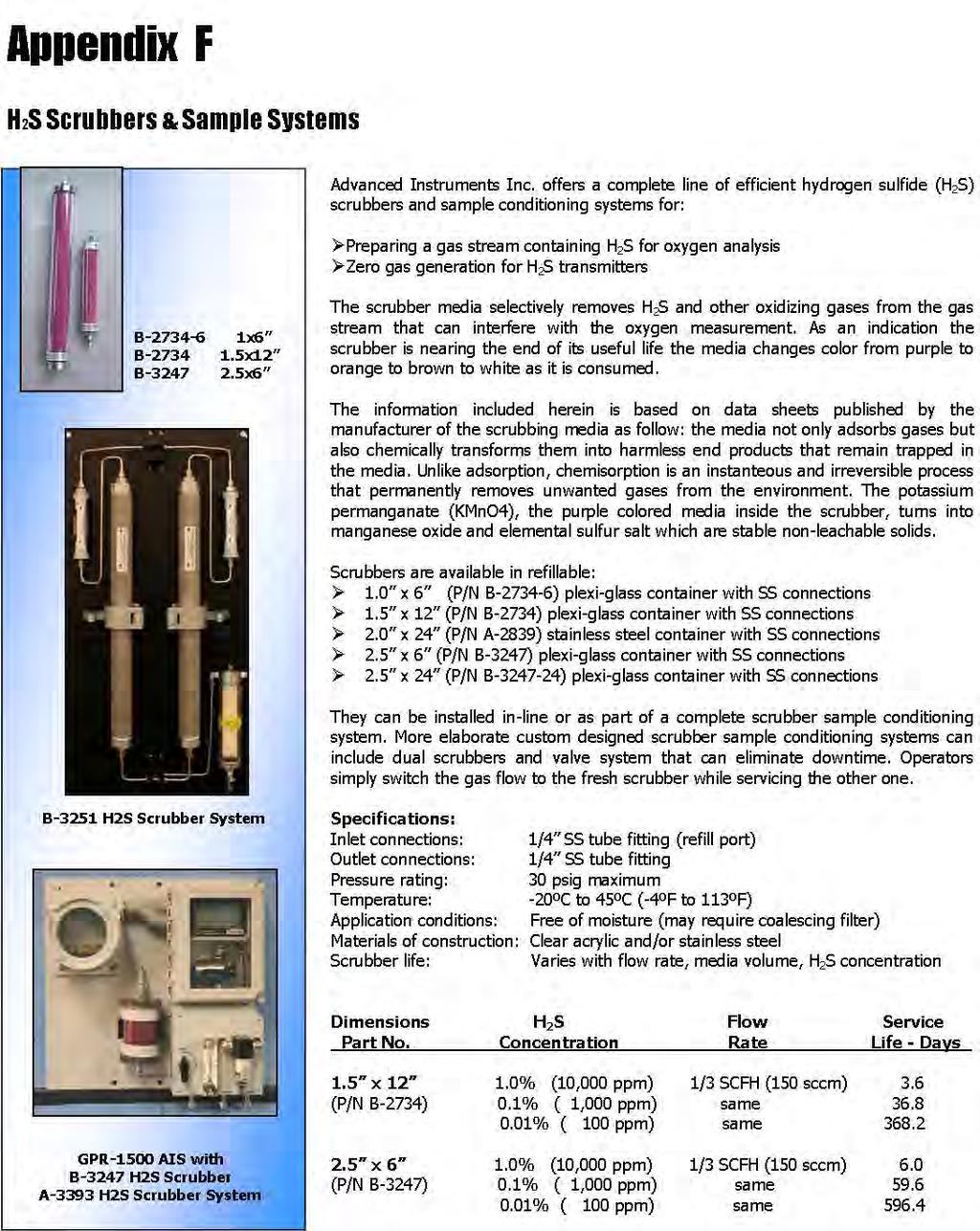
48 47
ATEX Certified for Hazardous Areas
 Technical Specifications * Accuracy: Analysis: Application: Approvals: < 2% of FS range under constant conditions 0-10, 0-100, 0-1000 PPM, 0-1%, 0-25% (CAL) FS Auto-ranging or manual lock on a single range
GPR-1500 N PPM Oxygen Transmitter. Advanced Sensor Technology
 Technical Specifications * Accuracy: Analysis: Application: < 2% of FS range under constant conditions 0-10, 0-100, 0-1000 PPM, 0-1%, 0-25% (CAL) FS Auto-ranging or manual lock on a single range Oxygen
GPR-1500 PPM Oxygen Transmitter
 Technical Specifications * Accuracy: Analysis: Application: < 2% of FS range under constant conditions 0-10, 0-100, 0-1000 PPM, 0-1%, 0-25% (CAL) FS Auto-ranging or manual lock on a single range Oxygen
GPR-1500 GB Glove Box PPM Oxygen Transmitter
 Technical Specifications * Accuracy: Analysis: Application: < 2% of FS range under constant conditions 0-10, 0-100, 0-1000 PPM, 0-1%, 0-25% (CAL) FS Auto-ranging or manual lock on a single range Oxygen
Drains Free Liquids. cul or ATEX Certified for Hazardous Areas. GPR-1500 AIS-LD PPM Oxygen Analyzer. UL Certified. ATEX Certified - Directive 94/9/EC
 Technical Specifications * Accuracy: < 2% of FS range under constant conditions cul or ATEX Certified for Hazardous Areas Analysis: Application: Approvals: 0-10, 0-100, 0-1000 PPM, 0-1%, 0-25% (CAL) FS
GPR-2500 N Oxygen Transmitter. Advanced Sensor Technology
 Technical Specifications * Accuracy: Analysis: Application: < 2% of FS range under constant conditions 0-1%, 0-5%, 0-10%, 0-25% FS ranges; auto-ranging or fixed single range Oxygen analysis in inert, hydrocarbon,
GPR-2500 / GPR-2500MO Oxygen Transmitter
 GPR-2500 / GPR-2500MO Oxygen Transmitter Owner s Manual 2855 Metropolitan Place, Pomona, CA 91767 USA Tel: 909-392-6900, Fax: 909-392-3665, e-mail: info@aii2.com, www.aii2.com Table of Contents Introduction
GPR-1100 ATEX Portable PPM O 2 Analyzer
 Technical Specifications * Accuracy: Analysis Ranges: < 2% of FS range under constant conditions 0-10, 0-100, 0-1000 PPM, 0-1%, 0-25% (CAL) FS Auto-ranging or manual lock on a single range ATEX Certified
GPR-1900 PPM Oxygen Analyzer
 Technical Specifications * Accuracy: Analysis: Application: < 2% of FS range under constant conditions 0-10, 0-100, 0-1000 PPM, 0-1%, 0-25% (CAL) FS Auto-ranging or manual lock on a single range Oxygen
GPR-1900 MS PPB Oxygen Analyzer
 Technical Specifications * Accuracy: Analysis: Application: Approvals: < 2% of FS range under constant conditions 0-1, 0-10, 0-100, 0-1000 PPM FS ranges Auto-ranging or manual lock on a single range Oxygen
GPR-18 ATEX Explosion Proof ppm O 2 Analyzer ATEX Directive 94/9/EC
 Technical Specifications Accuracy: Analysis: Application: Approvals: Area Classification: Alarms: Calibration: Compensation: Connections: Controls: Display: Enclosure: Flow Sensitivity: < 2% of FS range
Columbus Instruments
 0215-003M Portable O 2 /CO 2 /CH 4 Meter User s Manual Columbus Instruments 950 NORTH HAGUE AVENUE TEL:(614) 276-0861 COLUMBUS, OHIO 43204, USA FAX:(614) 276-0529 1 www.colinst.com TOLL FREE 1-800-669-5011
AMT-Ex Dewpoint Transmitter
 AMT-Ex Dewpoint Transmitter Instruction Manual Alpha Moisture Systems Alpha House 96 City Road Bradford BD8 8ES England Tel: +44 1274 733100 Fax: +44 1274 733200 email: mail@amsytems.co.uk web: www.amsystems.co.uk
L 100. Bubble-Tube Level System. Installation, Operation and Maintenance Instructions
 L 100 Bubble-Tube Level System Installation, Operation and Maintenance Instructions Figure 1 Contents Section Description Page 1.0 Introduction 2 2.0 Specifications 3 3.0 Installation 3 4.0 Warranty 6
Model PDT Dewpoint Transmitter
 Model PDT Dewpoint Transmitter Instruction Manual Alpha Moisture Systems Alpha House 96 City Road Bradford BD8 8ES England Tel: +44 1274 733100 Fax: +44 1274 733200 email: mail@amsytems.co.uk web: www.amsystems.co.uk
DTG - LCD Digital Temperature Gauge USER MANUAL
 DTG - LCD USER MANUAL Page 1 of 7 USERS GUIDE page 1. Description 3 2. Function 3 3. Safety Instruction 3 3.1. Safety Conventions 3 3.2. Proper Use 3 4. Installation 4 4.1. Unpacking 4 4.2. Storage 4 4.3.
FTS SUBMERSIBLE PRESSURE TRANSMITTER USER S MANUAL
 FTS SUBMERSIBLE PRESSURE TRANSMITTER USER S MANUAL TABLE OF CONTENTS PRODUCT OVERVIEW 2 I - USE AND CARE: 3 II - INSTALLATION: 5 III - GENERAL MAINTENANCE TIPS: 5 IV - APPENDIX: A-1 2-WIRE CURRENT LOOP
OXY Integral. INTERCON ENTERPRISES INC Tel: Fax: Internet:
 OXY Integral INTERCON ENTERPRISES INC Tel: 800 665 6655 Fax: 604 946 5340 E-Mail: sales@intercononline.com Internet: www.intercononline.com Manual Integral 2006 1 INDEX 2-3 PREFACE 4 INTRODUCTION 5 Principle
Design Features. General Description
 Model thermal Mass Flow Controllers are designed to indicate and control set flow rates of gases. The combines the characteristics and accuracy of conventional mass flow devices into a unique compact design
ACV-10 Automatic Control Valve
 ACV-10 Automatic Control Valve Installation, Operation & Maintenance General: The Archer Instruments ACV-10 is a precision automatic feed rate control valve for use in vacuum systems feeding Chlorine,
Instruction Bulletin Addendum For Pressure-Balanced In Situ Oxygen Probes
 Instruction Bulletin Addendum For Pressure-Balanced In Situ Oxygen Probes Instruction Bulletin Addendum IB PB1000 Part no. Serial no. Order no. Oxymitter 4000 Applicability: Used with pressure-balancing
SDX Submersible Depth Transmitter User Manual
 SDX Submersible Depth Transmitter User Manual July 2017 USER INFORMATION Stevens makes no warranty as to the information furnished in these instructions and the reader assumes all risk in the use thereof.
MODEL GT820 OXYGEN SENSOR
 INSTRUCTION MANUAL MODEL GT820 OXYGEN SENSOR 70046 The information and technical data disclosed by this document may be used and disseminated only for the purposes and to the extent specifically authorized
Electro-Pneumatic Converter YT-940 SERIES
 Electro-Pneumatic Converter YT-940 SERIES PRODUCT MANUAL VERSION 1.00 Contents 1. Introduction 3 1.1 General information for the users. 3 1.2 Manufacturer Warranty 3 1.3 Explosion Proof Warning. 4 2. Product
780S Ultra High Purity Series
 Smart Ultra High Purity Thermal Gas Mass Flow Meter Features Measures mass flow directly, no seperate temperature or pressure inputs required Field adjustment of critical flow meter settings via on-board
Best Practice Guide, Servomex 2700
 For full installations details refer to the. Best Practice Guide, Servomex 2700 Mounting: General Guidelines: Servomex 2700 Control Units and air supplies (utilities units) should, ideally, be mounted
OPERATOR S MANUAL Ar-Gone Weld Gas Analyzer
 July 2011 OPERATOR S MANUAL Ar-Gone Weld Gas Analyzer WARNING! Before operating this product, read and understand this Operator s Manual. Become familiar with the potential hazards of this unit. Contact
SDX Submersible Depth Transmitter User Manual
 SDX Submersible Depth Transmitter User Manual October 2007 USER INFORMATION Stevens makes no warranty as to the information furnished in these instructions and the reader assumes all risk in the use thereof.
I/P Transducer Positioner Module
 I/P Transducer Positioner Module VRC P/N: 7958032 Installation, Operation and Maintenance Instructions 2.09 [53.1] 1.30 [32.9] 2.97 [75.5] 0.78 [19.8] 0.18 [4.4] 1.42 [36.1] n.18 MOUNTING HOLES (2) PLACES
GAS FUEL VALVE FORM AGV5 OM 8-03
 ALTRONIC AGV5 OPERATING MANUAL GAS FUEL VALVE FORM AGV5 OM 8-03 WARNING: DEVIATION FROM THESE INSTALLATION INSTRUCTIONS MAY LEAD TO IMPROPER ENGINE OPERATION WHICH COULD CAUSE PERSONAL INJURY TO OPERATORS
EASIDEW TRANSMITTER with Current Source Output
 EASIDEW TRANSMITTER with Current Source Output INSTALLATION, OPERATION AND MAINTENANCE MANUAL Issue March 2002 2 TABLE OF CONTENTS SECTION PAGE 1. INTRODUCTION 3 1.1 General 3 1.2 Ceramic Sensing Element
Model 130M Pneumatic Controller
 Instruction MI 017-450 May 1978 Model 130M Pneumatic Controller Installation and Operation Manual Control Unit Controller Model 130M Controller is a pneumatic, shelf-mounted instrument with a separate
DF-310E PROCESS ANALYSERS APPLICATIONS FEATURES
 PROCESS ANALYSERS DF-310E The DF-310E is a Coulometric sensor based oxygen analyzer designed to measure trace and percent level oxygen in pure and multi-gas backgrounds for process and quality control
Title: Standard Operating Procedure for R&R Environmental Devices Model MFC201 Gas Dilution Calibrator
 Procedure No: SOP-029 Revision No: 1.1 (December 29, 2010) Page No.: 1 of 7 1. INTRODUCTION AND SCOPE To obtain timely data for the purpose of air quality assessment, air quality trend reporting, air quality
AFC. SDPROC and AFC Analog Mass Flow Controller ANALOG MASS FLOW CONTROLLERS. Principles of Operation. Design Features
 ANALOG MASS FLOW CONTROLLERS Model AF mass fl ow controllers are designed to indicate fl ow rates and control set fl ow rates of gases. Each of these units incorporates an advanced straight tube sensor
MASS FLOW SYSTEMS MASS FLOW MEASURING, CONTROLLING AND BLENDING SYSTEMS
 MASS FLOW SYSTEMS MASS FLOW MEASURING, CONTROLLING AND BLENDING SYSTEMS Using state-of-the-art measuring and microprocessor technologies, Advanced has assembled a series of systems which can measure mass
O3 3E 1 F Gas Sensor Module
 Product Information Pack O3 3E 1 F Gas Sensor Module (Ozone) CONTENTS Product Data Sheet Product Specification 2 Poisoning and Cross Sensitivities 3 Operating Instructions Introduction 4 Electrostatic
T EK-SUB 4800C 19 mm Submersible Level Transmitter
 Technology Solutions T EK-SUB 4800C 19 mm Submersible Level Transmitter Instruction Manual Document Number: IM-4800C www.tek-trol.com Table of Contents 1 Safety Instructions... 2 1.1 Intended Use... 2
Inert Air (N2) Systems Manual
 Systems Manual") INSTRUCTION MANUAL Inert Air (N2) Systems Manual N2-MANUAL 2.10 READ AND UNDERSTAND THIS MANUAL PRIOR TO OPERATING OR SERVICING THIS PRODUCT. GENERAL INFORMATION Positive pressure nitrogen gas pressurizing
INSTRUCTION MANUAL Inert Air (N2) Systems Manual N2-MANUAL 2.10 READ AND UNDERSTAND THIS MANUAL PRIOR TO OPERATING OR SERVICING THIS PRODUCT. GENERAL INFORMATION Positive pressure nitrogen gas pressurizing
OxyCheq Expedition-X Oxygen Analyzer. Operator s Manual
 OxyCheq Expedition-X Oxygen Analyzer Operator s Manual OxyCheq 3528 Russell Road Marianna, Florida 32446 USA Tel: 850.482.0385 Email: oxy@oxycheq.com Web: http://oxycheq.com CONTENTS 1.0 Introduction..
Title: Standard Operating Procedure for Dasibi Model 5008 Gas Dilution Calibrator
 Procedure No: SOP-034 Revision No: 1.0 Revised Dec. 29, 2010 Page No.: 1 of 10 1. INTRODUCTION AND SCOPE This procedure is intended to describe the operations of the Dasibi model 5008 calibrator. The Dasibi
Operating Instructions
 Operating Instructions Sensors Type 705 H 2 S Sensor and Transmitter for Electrochemical Cells Ul Certified HELPING TO MAKE A SAFER WORLD Ensure that you read and understand these operating instructions
Technical Information
 Technical Information Installation, Operation, Installation, Operation and Maintenance and Maintenance Manual Manual Balston Model 75700-K728 Nitrogen Generator Figure 1-75700-K728 Overall Dimensions These
XMO2. Panametrics Smart Oxygen Analyzer. Applications. Features. bhge.com. An oxygen transmitter for use in:
 XMO2 Panametrics Smart Oxygen Analyzer Applications An oxygen transmitter for use in: Inerting/blanketing liquid storage tanks Reactor feed gases Centrifuge gases Catalyst regeneration Solvent recovery
ACCURACY, PERFORMANCE, AND HANDLING OF OIL-FILLED DIGIQUARTZ PRESSURE INSTRUMENTATION
 Application Note Doc. G8108-001 Rev. A - 23-Jul-02 ACCURACY, PERFORMANCE, AND HANDLING OF OIL-FILLED DIGIQUARTZ PRESSURE INSTRUMENTATION For more information regarding Digiquartz products contact: Paroscientific,
The Ins and Outs of I/P Transducers
 The Ins and Outs of I/P Transducers By Mark B. Levine, ControlAir Inc. General description I/P transducers are versatile instruments that use an electrical control signal to proportionally regulate gas
High-performance submersible pressure transmitter For level measurement Model LH-10
 Electronic pressure measurement High-performance submersible pressure transmitter For level measurement Model LH-10 WIKA data sheet PE 81.09 Applications Level measurement in rivers and lakes Deep well
2 Sentry MCL Installation, Operation & Maintenance
 Gas Liquid & Slurry Solid & Powder Steam & Water Installation, Operation & Maintenance Manual Original Instructions Liquid Sampling Manual Low-Emission Samplers S-GA-IOM-00249-7 11-17 Sentry MCL 966 Blue
Operation and Maintenance Manual
 Operation and Maintenance Manual GDS 49 Remote 4 20mA Sensor Transmitter for Toxic Gases GDS Corp. 1245 Butler Road League City, TX 77573 409 927 2980 409 927 4180 (Fax) www.gdscorp.com CAUTION: FOR SAFETY
DF-550E PROCESS ANALYSERS APPLICATIONS FEATURES
 PROCESS ANALYSERS DF-550E The DF-550E Nano Trace oxygen analyser is a Coulometric sensor based analyser designed to measure oxygen as a contaminant at ultra trace levels in ultra high purity electronic
3.0 Pressure Transmitter Selection
 3.0 Pressure Transmitter Selection Each Tronic Line pressure transmitter has different features to meet specific performance, environmental, and price requirements. It is not possible to describe every
LPS Product Guide. LPS Series Nitrogen Generators. N2-GEN LPS TM - Layup Protection System Copyrighted All Rights Reserved
 LPS Product Guide N2-GEN LPSTM LPS Series Nitrogen Generators N2-GEN LPS TM - Layup Protection System Copyrighted All Rights Reserved - 2014 p 888 526 6284 e info@southteksystems.com w www.southteksystems.com
GILMONT ACCUCAL FLOWMETERS
 OPERATING MANUAL GILMONT ACCUCAL FLOWMETERS 28W092 Commercial Ave. Barrington, IL U.S.A. 60010-2392 (847) 381-4888 (847) 381-7053 (Fax) 800-962-7142 www.barnant.com e-mail: barnant@barnant.com A-1299-0766
Installation, Operation, and Maintenance Manual Parker Balston Model N2-04 Nitrogen Generator
 Installation, Operation, and Maintenance Manual Parker Balston Figure 1 - N2-04 Nitrogen Generator These instructions must be thoroughly read and understood before installing and operating this product.
Preferred Instruments Danbury, CT USA
 Tank Level Sensor Model TG-EL-WF-xx Installation & Operation Instructions SDI-TG-EL-WF March 6, 2006 Preferred Instruments Danbury, CT USA www.preferredinstruments.com CONTENTS Installation Pg. 2 Calibration
Autocalibration Systems For In Situ Oxygen Analyzers
 Product Data Sheet PDS 106-340AC SPS 4000, IMPS 4000, and MPS 3000 January, 1999 Autocalibration Systems For In Situ Oxygen Analyzers Cost-effective autocalibration systems for installations ranging from
Model B Wire Wet Oxidant Gas Transmitter. 6 Iron Bridge Drive Unit 1 & 2 Gatehead Business Park
 Model B12-69 2-Wire Wet Oxidant Gas Transmitter Home Office European Office Analytical Technology, Inc. ATI (UK) Limited 6 Iron Bridge Drive Unit 1 & 2 Gatehead Business Park Collegeville, PA 19426 Delph
ANNEX AMENDMENTS TO THE INTERNATIONAL CODE FOR FIRE SAFETY SYSTEMS (FSS CODE) CHAPTER 15 INERT GAS SYSTEMS
 CHAPTER 15 INERT GAS SYSTEMS") Annex 3, page 2 ANNEX AMENDMENTS TO THE INTERNATIONAL CODE FOR FIRE SAFETY SYSTEMS (FSS CODE) CHAPTER 15 INERT GAS SYSTEMS The text of existing chapter 15 is replaced by the following: "1 Application This
Annex 3, page 2 ANNEX AMENDMENTS TO THE INTERNATIONAL CODE FOR FIRE SAFETY SYSTEMS (FSS CODE) CHAPTER 15 INERT GAS SYSTEMS The text of existing chapter 15 is replaced by the following: "1 Application This
Bante810 Benchtop Dissolved Oxygen Meter Instruction Manual
 Bante810 Benchtop Dissolved Oxygen Meter Instruction Manual BANTE INSTRUMENTS CO., LTD Bante810 Benchtop Dissolved Oxygen Meter 1 Introduction Thank you for selecting the Bante810 benchtop dissolved oxygen
Intelligent SUNTEX DC-5310(RS) Dissolved Oxygen Transmitter
 Dissolved Oxygen Transmitter") Intelligent SUNTEX DC-5310(RS) Dissolved Oxygen Transmitter Overview C % ppm 4~20mA Analog Output ppb Power Supply 100~240 VAC mg/l Dimensions 96 x 96 x 132mm RS-485 Digital Output (for DC-5310-RS only)
Intelligent SUNTEX DC-5310(RS) Dissolved Oxygen Transmitter Overview C % ppm 4~20mA Analog Output ppb Power Supply 100~240 VAC mg/l Dimensions 96 x 96 x 132mm RS-485 Digital Output (for DC-5310-RS only)
analytical bulk flow distance FLOW level pressure temperature industrial communication
 analytical bulk flow distance level pressure temperature industrial communication isolv THERMAL MASS METER Measuring Principle Self-heated Sensor Reference Sensor isolv Thermal Mass Flow Meters have two
Operation & Maintenance Manual GDS-68XP
 Operation & Maintenance Manual GDS-68XP Process Gas Monitor for Low Oxygen Applications GDS Corporation 2513 Hwy 646 Santa Fe, Texas 77510 (409) 927-2980 (409) 927-4180 (Fax) www.gdscorp.com CAUTION: FOR
Transmitter CS 21 Operation Manual
 Transmitter CS 21 Operation Manual Content Page For your Safety 3 General Description 3 Detection Principle 4 Operational Notes 4 Design 4 Mounting Position of CS21 5 Mounting 6 Installation of Electrical
DPC-30 DPC-100. Reference Manual
 DPC-30 DPC-100 Reference Manual 1. Introduction 1.1 Description The Martel DPC Digital Pneumatic Calibrator improves upon traditional dial gauge pneumatic calibrators. The Martel DPC improves accuracy,
DK46 - DK800 Supplementary instructions
 DK46 - DK800 Supplementary instructions Variable area flowmeter Device category II2G with electrical internals Additional Ex manual KROHNE CONTENTS DK46 - DK800 1 Safety instructions 3 1.1 General... 3
INSTRUCTION MANUAL MP4AR Remote Convection Gauge Range: 1 x 10⁻³ Torr to 1 x 10+3 Torr
 INSTRUCTION MANUAL MP4AR Remote Convection Gauge Range: 1 x 10⁻³ Torr to 1 x 10+3 Torr A DIVISION OF THE FREDERICKS COMPANY 2400 PHILMONT AVE. HUNTINGDONVALLEY, PA 19006 PARTS LIST 1 3 4 2 # QTY ITEM DESCRIPTION
H-DIL Hydrogen/Oxygen Sample-Draw Detector Operator s Manual
 35-3001-06H-DIL Hydrogen/Oxygen Sample-Draw Detector Operator s Manual Part Number: 71-0346 Revision: A Released: 8/7/17 www.rkiinstruments.com WARNING Read and understand this instruction manual before
GFM. Typical Aluminum GFM Mass Flow Meter NIST MASS FLOW METERS. Principles of Operation. Design Features
 Design Features Rigid metallic construction. Maximum pressure of 1000 psig (70 bars). Leak integrity 1 x 10⁻⁷ of helium. NIST traceable certification. Built-in tiltable LCD readout. 0-5 Vdc and 4-20 ma
Electropneumatic Transducer (I/P) Installation, Operation and
 Installation, Operation and") Nitra NCP1 Series Electropneumatic Transducer (I/P) Installation, Operation and Maintenance Instructions Ordering Information Contents Part Number I/P Transducers Output Range Input psig bar Section Description
Nitra NCP1 Series Electropneumatic Transducer (I/P) Installation, Operation and Maintenance Instructions Ordering Information Contents Part Number I/P Transducers Output Range Input psig bar Section Description
Expert Hydrostatic Level Transmitters
 Expert Hydrostatic s General Features MJK Expert hydrostatic level transmitters are designed for level measurement by submerging the transmitter in open channels, drains and tanks. Expert hydrostatic level
_ pressure transducers. User Manual
 _ pressure transducers User Manual summary introduction DescriPTION preliminary checks Installation taking measurements data management Troubleshooting maintenance Appendix 1 Page 4 Page 5 Page 6 Page
G92 Series BASOTROL Automatic Pilot Gas Valve
 Installation Instructions Issue Date September 17, 2008 G92 Series BASOTROL Automatic Pilot Gas Valve Installation IMPORTANT: Only qualified personnel should install or service BASO Gas Products. These
Type N-10, N-11 Hazardous Area Non-incendive Transmitters
 Electronic Pressure Catalog > Hazardous Area > N-10, N-11 Type N-10, N-11 Hazardous Area Non-incendive Transmitters Applications Natural gas compressors Wellhead monitoring Pipeline pressure General industrial
ECS Protector Nitrogen Generator PGEN-30 (PGEN-30E)
") ECS Protector PGEN-30 (PGEN-30E) Specifications For use under U.S. Patents 8,720,591, 9,144,700 and 9,186,533 Dimensions (cabinet): 24.5 (W) x 52.5 (H) x 8.5 (D) (622mm(W) x 1,334mm(H) x 216mm(D)) Dimensions
ECS Protector PGEN-30 (PGEN-30E) Specifications For use under U.S. Patents 8,720,591, 9,144,700 and 9,186,533 Dimensions (cabinet): 24.5 (W) x 52.5 (H) x 8.5 (D) (622mm(W) x 1,334mm(H) x 216mm(D)) Dimensions
SPECIFICATIONS Type: Twin stack, single phase Tank: 4 gallon Air Output: PSI; PSI Max PSI: 125 PSI HP: 1.
 2 GALLON TWIN STACK AIR COMPRESSOR Model: 9526 DO NOT RETURN TO STORE. Please CALL 800-348-5004 for parts and service. CALIFORNIA PROPOSITION 65 WARNING: You can create dust when you cut, sand, drill or
RAM Operation Manual. Worldwide Manufacturer of Gas Detection Solutions
 RAM 4021 Operation Manual Worldwide Manufacturer of Gas Detection Solutions TABLE OF CONTENTS RAM 4021 For Your Safety... 2 Description.... 2 Setup Mode.... 2 Lights/Alarms.... 3 Operation.... 4 Calibration....
RDK-408D2 Cold Head. Technical Manual. SHI-APD Cryogenics Inc Vultee Street Allentown, PA U.S.A. Revision A: September 2005
 RDK-408D2 Cold Head Technical Manual SHI-APD Cryogenics Inc. 1833 Vultee Street Allentown, PA 18103-4783 U.S.A. Revision A: September 2005 (Reference SHI Manual: December 18, 2003 266404A CD32ZZ-160A)
Calibration Gas Instrument INSTRUCTION MANUAL. Release I. Advanced Calibration Designs, Inc.
 Advanced Calibration Designs, Inc. Calibration Gas Instrument INSTRUCTION MANUAL Release I www.goacd.com Instruction Manual Gas Generator Release I TABLE OF CONTENTS I. General Description Page 2 II. Start-Up
Pegas 4000 MF Gas Mixer InstructionManual Columbus Instruments
 Pegas 4000 MF Gas Mixer InstructionManual Contents I Table of Contents Foreword Part I Introduction 1 2 1 System overview... 2 2 Specifications... 3 Part II Installation 4 1 Rear panel connections...
D10S/D20S Wall/Post Mount Inflator Quick Start Manual
 PART NUMBER SERIAL NUMBER D10S/D20S Wall/Post Mount Inflator Quick Start Manual Please read and save these instructions. Read carefully before attempting to assemble, install, operate or maintain the product
SAFETY MANUAL FOR FLAMMABLE PRODUCT TRANSFER
 SAFETY MANUAL FOR FLAMMABLE PRODUCT TRANSFER SUPPLIMENT TO eom IMPORTANT READ THIS MANUAL BEFORE PRODUCT INSTALLATION, OPERATION, INSPECTION & MAINTENANCE Tougher and more rigid guidelines are being established
BGA244 Binary Gas Analyzer
 Quick Start Guide Revision 1.0 Certification Warranty Service certifies that this product met its published specification at the time of shipment. This product is warranted against defects in materials
MEDICAL EQUIPMENT CATALOG
 THE MOST TRUSTED MEDICAL EQUIPMENT IN NORTH AMERICA MEDICAL EQUIPMENT CATALOG Total Components Including Bulk Oxygen Supply, Back up and Delivery Equipment Designs for High Pressure, Liquid or Bulk Applications
TEK-SUB 4800B. Submersible Level Transmitter. Flow Level Temperature Pressure Valves Analyzers Accessories TekValSys LEVEL
 Technology Solutions TEK-SUB 4800B Submersible Level Transmitter LEVEL Flow Level Temperature Pressure Valves Analyzers Accessories TekValSys Introduction The Tek-Sub 4800B Submersible Level Transmitter
BUBBLER CONTROL SYSTEM
 BUBBLER CONTROL SYSTEM Description: The LDBCS is a fully automatic bubbler system, which does liquid level measurements in water and wastewater applications. It is a dual air compressor system with, air
Model 106 DPI "Micro-switch" Installation and Operating Instructions
 Mid-West Instrument Model 106 DPI "Micro-switch" Installation and Operating Instructions BULLETIN NO. IM116DPImicro/09A Replaces --- INSPECTION Before installation carefully check the Model Number on each
BUBBLER CONTROL SYSTEM
 BUBBLER CONTROL SYSTEM Description: The HDBCS is a fully automatic bubbler system, which does liquid level measurements in water and wastewater applications. It is a dual air compressor system with, air
Pneumatic high-pressure controller Model CPC7000
 Calibration technology Pneumatic high-pressure controller Model CPC7000 WIKA data sheet CT 27.63 Applications Automotive and avionics industry Industry (laboratory, workshop and production) Transmitter
BI-680 Online Dissolved Oxygen Controller Instruction Manual
 BI-680 Online Dissolved Oxygen Controller Instruction Manual BANTE INSTRUMENTS CO., LTD BI-680 Online Dissolved Oxygen Controller 1 Introduction Thank you for selecting the BI-680 online dissolved oxygen
AMS 6916 Board mount pressure sensor with ratiometric analog output
 FEATURES Piezoresistive pressure sensor with amplified analog output Calibrated and temperature compensated Ratiometric voltage output, 0.5 4.5 V Digital signal conditioning, 12 bit output resolution Differential,
Alphasense 4-20 ma transmitters offer convenience and easy maintenance for toxic sensors:
 ALPHASENSE USER MANUAL Page 1 4-20mA Transmitter for Toxic Sensors UMTOX-1 Issue 4 1 INTRODUCTION The Transmitter PCB includes circuitry for a three electrode toxic sensor to convert the µa output signal
Installation and Operation Manual
 Installation and Operation Manual WIKA FLR-SBDF / BLR-SBDF Magnetic Level Transmitter (Please retain for future usage) Contact: Gayesco-WIKA USA, L.P. 229 Beltway Green Boulevard Pasadena, TX 77503 www.wika.com
Transmitter CS 21 Operation Manual
 Transmitter CS 21 Operation Manual 1194 Oak Valley Drive, Suite 20, Ann Arbor, MI 48108 800-959-0573 734-769-1888 Content Page For your Safety 3 General Description 3 Detection Principle 4 Operation 4
Technical Data Sheet MF010-O-LC
 Technical Data Sheet MF010-O-LC - 1 - 1. Properties The oxygen measuring system MF010-O-LC determines the oxygen content in gas mixtures up to a temperature of 250 C. It is particularly suitable for the
User s Guide Temperature Sensor Converter TSC-599
 User s Guide Temperature Sensor Converter TSC-599 ILX Lightwave Corporation 31950 Frontage Road Bozeman, MT, U.S.A. 59715 U.S. & Canada: 1-800-459-9459 International Inquiries: 406-556-2481 Fax 406-586-9405
GASGUARD VENT LINE3 Ammonia Sensor OPERATING & INSTALLATION MANUAL
 GASGUARD VENT LINE3 Ammonia Sensor OPERATING & INSTALLATION MANUAL Operating and Installation Manual Warning Use this product only in the manner described in this manual. If the equipment is used in a
Autocalibration Systems for In Situ Oxygen Analyzers
 Product Data Sheet PDS 106-340AC.A01 February, 2006 SPS 4001B, IMPS 4000 and MPS 3000 Autocalibration Systems for In Situ Oxygen Analyzers Cost-effective autocalibration systems for installations ranging
Oxygen Measurement in Natural Gas
 Oxygen Measurement in Natural Gas Application Background Natural Gas Fuel is primarily methane. If it were pure methane, it would be very simple to transport and use. But it comes out of the well as a
TECHNICAL INFORMATION
 TECHNICAL INFORMATION Installation, Operation, and Maintenance Balston Model 75-77 Nitrogen Generator Figure 1-75-77 Overall Dimensions These instructions must be thoroughly read and understood before
! Warning, refer to accompanying documents.
 About this Manual To the best of our knowledge and at the time written, the information contained in this document is technically correct and the procedures accurate and adequate to operate this instrument