Operating Instructions
|
|
|
- Mercy Pitts
- 5 years ago
- Views:
Transcription
1 Operating Instructions PRECISION AIR ENTRAINMENT METER Model: (CT-126A)
2 TABLE OF CONTENTS I. GENERAL INFORMATION...1 II. RELATED USER DOCUMENTATION...2 FIGURE 1 -- AIR ENTRAINMENT METER...3 III. USING THE METER...4 IV. OPERATING INSTRUCTIONS FOR MULTI-RANGE SCALE...6 V. CALIBRATION CHECK TEST...7 VI. CALIBRATING THE AIR METER TO ANY READING (OTHER THAN STANDARD...9 VII. CT-126E AIR METER NOMOGRAPH VIII. MAINTENANCE IX. SPECIFICATIONS PARTS LIST TABLE 1 -- PERCENTAGE VALUES TABLE -- % MOISTURE BY VOLUME ( %) TABLE -- % MOISTURE BY VOLUME ( %) Rev. 11: 8/15
3 PRECISION AIR ENTRAINMENT METER MODEL (CT-126A) I. GENERAL INFORMATION Controlling entrained air in concrete is one of the biggest concerns in modern concrete manufacturing. The model (CT-126A) Precision Air Entrainment Meter offers the concrete engineer or technician the finest instrument available today for testing and designing concrete mixes. This superior meter can precisely determine the amount of air entrained in concrete, by simplifying the application of Boyle's Law. The direct reading requires no adjustment for barometric pressure changes, and one person can quickly and easily conduct the test. The (CT-126A) container is rigid, with a capacity of cubic feet, providing a reliable device for precisely performing the unit weight test. The tare weight in grams is conveniently stamped on the bottom. The meter's multi-range feature accurately measures entrained air to 22%. This feature, exclusive to the (CT-126A), allows the user to measure entrained air in numerous other materials besides concrete. For example, this cost-effective meter can also be used to test materials such as mortar, plaster, soil and lightweight concrete. The air meter, when used along with the supplied Nomograph, quickly and easily measures the aggregate's specific gravity and free-moisture percentage. The instrument is constructed of the finest materials available, for superior durability and effective operation. It is supplied complete with a striking bar and syringe. The Air Meter and the Nomograph together offer an exceptional combination not found anywhere else in the industry. 1
4 II. RELATED USER DOCUMENTATION These operating instructions do not contain all the necessary information on the specific test procedures to measure entrained air in concrete. Please refer to ASTM C-231 or AASHTO T-152 for more information. 2

5 FIGURE 1 -- AIR ENTRAINMENT METER 3
6 III. USING THE METER (See Figure 1) A. Remove the lid and place the concrete to be tested in three equal layers in the material container (#1). Rod each layer 25 times, using the tamping rod provided by ELE. Remove excess concrete by sliding the striking bar (#3) in a sawing motion across the top flange, until the container is full, but level. B. Remove all sand and mortar from the lip of the container (#5). Ensure that the underside of the lid is free of any material, such as sand or grit, which may damage the lip and clamps. C. Open both petcocks (#8 & #9) found on top of lid. D. Carefully position the lid on the material container. Close the four toggle clamps (#6), making sure the handle is flush against the container. CAUTION: NEVER PRESSURIZE CONTAINER UNTIL CLAMPS ARE COMPLETELY CLOSED. E. Using a syringe, carefully pour water into funnel (#7) until it begins to come out of center petcock (#8) on lid. NOTE: When using the syringe, force the water out slowly to avoid expulsion of air. F. Gently jar the container or tap the lid until the air bubbles no longer come out of the center petcock. Add more water to be sure only water, no air, comes out. Close both petcocks (#8 & #9). 4
7 G. The main air valve is always closed. Close air bleed valve (#10), located at end of air receiver. Use air pump handle (#11), located opposite of the air bleed valve, to gently pump air into receiver until the black gauge hand (#12) is on the yellow starting line. NOTE: If the black gauge hand should go past the yellow starting line, gently tap the gauge while cracking the air bleed valve (#10), located at end of air receiver, until the gauge hand is situated exactly on the yellow starting line. Quickly close the air bleed valve. H. Press the main air valve lever down for 5-7 seconds to pressurize container. After pressurizing, jar the container slightly to allow for possible rearrangement of the particles. Gently tap gauge until its black-hand stops moving, and note the reading. This reading is the air entrainment percentage. I. After the reading is taken, release the main air valve lever to prevent pressure from going from the container into the air receiver. J. Before removing the lid, release pressure from the container by slowly opening the center petcock (#8)and then opening the funnel petcock (#9). Some water will spurt out. K. After the lid has been removed, open air bleed valve (#10) to release air from the air receiver. L. In cases where there are large voids in the aggregate and it is necessary to deduct their volume from the measured air content, complete the following steps: 1. Place the same amount of each size aggregate used for the test in the material container. 2. Fill the container with water. 3. Complete steps B through H as in the regular determination for air content. This reading is the aggregate correction factor. 5
8 IV. OPERATING INSTRUCTIONS FOR MULTI-RANGE SCALE (See Figure 1) For samples containing more than 10% air. International A. Follow Section III, Steps A through H in regular operating instructions up to gently tapping the gauge until its hand stops moving. B. Close the main air valve (#4) and once again pump air into air receiver. To return gauge hand to the yellow starting point, bleed air from receiver through air bleed valve (#10). After pressure is applied to sample, do not open center and funnel petcocks (#8 & #9) until test is completed. C. Open main air valve (#4) approximately one turn. After pressurizing, jar the container slightly to allow for possible rearrangement of the particles. Gently tap gauge until its black-hand stops moving. Read air percentage on extended scale (green section of gauge face). NOTE: Always close main air valve (#4) before releasing pressure from either the material container (#1) or air receiver. If this is not done, water will be drawn into the air receiver, adversely affecting future measurements. If water is accidentally drawn into air receiver, open air bleed valve (#10) and tip the lid, letting the water run out of the bleeder valve. Stroke the pump handle several times to blow out the last traces of water. 6
9 V. CALIBRATION CHECK TEST A. Fill the material container with water. Making sure the container is level, remove standpipe screwed into center petcock (#8) and screw it tightly into funnel petcock (#9) on underside of lid. B. Wipe the lip of container clean and dry. C. Unscrew and remove the gauge window. D. Close the main air valve (#4) located on the top of the air receiver. Open both the center and funnel petcocks (#8 & #9). E. Carefully position the lid on material container and close the four toggle clamps (#6), making sure clamp handle is flush against the container. CAUTION: NEVER PRESSURIZE CONTAINER UNTIL CLAMPS ARE COMPLETELY CLOSED. F. Using a syringe, carefully pour water into funnel (#7) until it begins to come out of center petcock (#8) on lid. NOTE: When using the syringe, force the water out slowly to avoid expulsion of air. G. Gently jar the container or tap the lid until the air bubbles no longer come out of the center petcock. Add more water to be sure only water, no air, comes out. Close both petcocks (#8 & #9). 7
10 H. Check that the main air valve (#4) is closed. Close air bleed valve (#10), located at end of air receiver. Use air pump handle (#11), located opposite of the air bleed valve, to gently pump air into receiver until the black gauge hand (#12) is on the yellow starting line. If the black gauge hand should go past the yellow starting line, gently tap the gauge while cracking the air bleed valve (#10), located at end of air receiver, until the gauge hand is situated exactly on the yellow starting line. Quickly close the air bleed valve. I. Use a syringe (#16) to remove all water from funnel (#7). J. Open funnel petcock (#9). To allow water to enter the funnel, slowly and carefully open the main air valve lever #4. K. When water exactly meets waterline (#15) inside funnel, release main air valve lever (#4) and close funnel petcock (#9). L. Open the material container s main air valve (#4) about ½ turn. Tap gauge until hand stops moving. Gauge hand should stop on 1.2%; if it does not, the yellow starting point arrow should be readjusted, using the following steps: 1. If gauge reads less than 1.2%, move the yellow starting point arrow, in a counterclockwise direction, the distance that is equal to the amount the gauge hand is under 1.2%. 2. If gauge reads more than 1.2%, move the yellow starting point arrow, in a clockwise direction, the distance that is equal to the amount the gauge hand is over 1.2%. M. After the calibration-check test is completed, release pressure by turning the air bleed valve (#10) so that the gauge hand will return to its initial position. Close the air bleed valve (#10). N. Before removing the lid, release pressure from the container by slowly opening the center petcock (#8) first and then opening the funnel petcock (#9). Some water will spurt out. 8
11 O. Return the standpipe to its proper location in center petcock (#8). P. Replace the gauge window. VI. CALIBRATING THE AIR METER TO ANY READING (OTHER THAN STANDARD) The calibration method described in this section differs from the standard 1.2% calibration; the container's center vent petcock is opened to atmosphere and then closed before pressure is applied through the main air valve. This brings the air over the water in the container to atmospheric pressure. The volume of the (CT-126A) container is 1/4 cubic foot, or 432 cubic inches. The meter may be calibrated by removing 4.32 cubic inches (70.79cc) of water for each percentage point of gauge reading as follows: A. Fill the container with water, following the steps outlined in Section III, Steps A through E of the operating instructions. B. Use syringe to remove all water from funnel (#16). C. Making sure air bleed valve (#10) is closed, pump air into chamber until pointer nears red line. D. Open main air valve (#4). Crack the funnel petcock (#9), letting water rise in the funnel (#16) to desired level. Close the petcock (#9). DO NOT LET THE FUNNEL OVERFLOW WITH WATER. 9
12 E. Use a graduated pipette to remove specific volume of water, using the values given in attached Table 1. If a sufficient amount of water was not removed from funnel, steps C and D in Section III may be repeated. EXAMPLE: To calibrate (CT-126A) for 4%, take out cc of water; to calibrate for 7%, take out cc of water. NOTE: The maximum volume of water that can be taken out through the funnel in this way is limited by the length of the standpipe, which should be under water at its lower end. The limit for the (CT-126A) is almost 850cc. F. The main air valve is always closed. Slowly open the container's center vent petcock (#8), to equalize the inside pressure with the atmosphere. G. Open the funnel petcock (#9), so that both petcocks are now open. Excess water in the funnel will flow back into the container (#1). H. Close both petcocks (#8 & #9). Pump air into the reservoir until the pointer nears the red line. I. Crack open the air bleed valve (#10) while gently tapping on the gauge (#13). When the pointer is exactly on the yellow starting line, close the air bleed valve (#10). J. Slowly open the main air valve (#4) and tap gently on the gauge (#13) until the pointer comes to a steady position. The pointer should now show the exact percentage value given in Table 1 for the specific amount of water removed. If the pointer does not read the exact percentage, investigate the following situations: 1. Was the wrong volume of water removed? 2. Is cement sticking to the inside of the container, changing its volume? 3. Are there leaks in the gaskets or fittings? 10
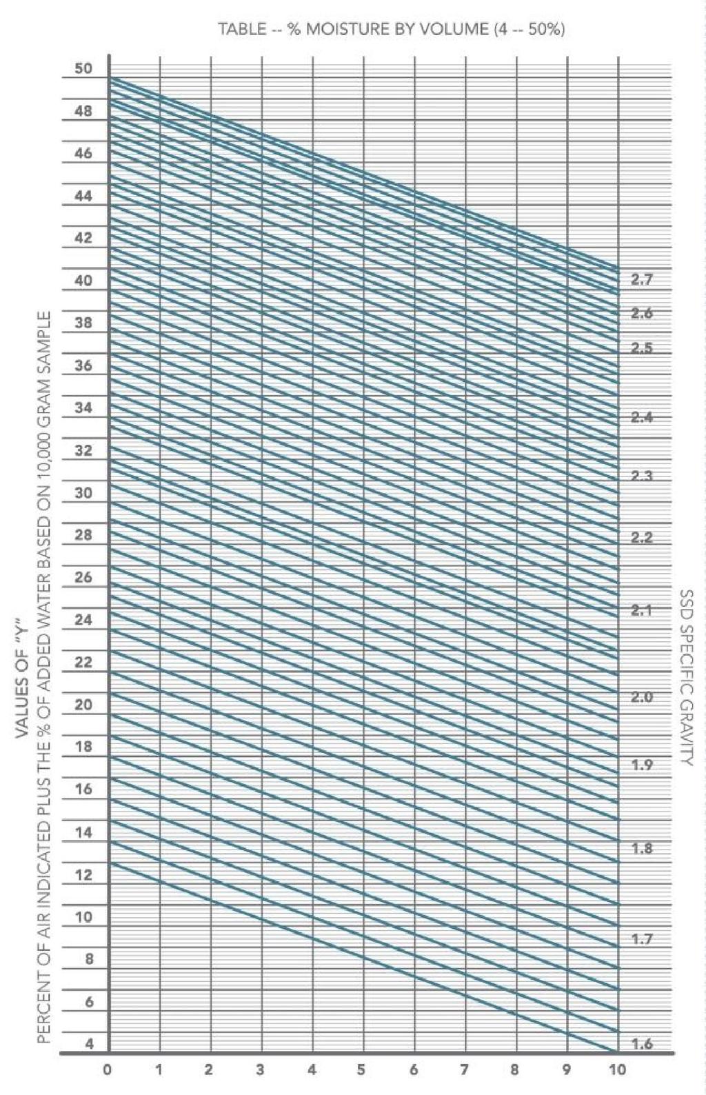
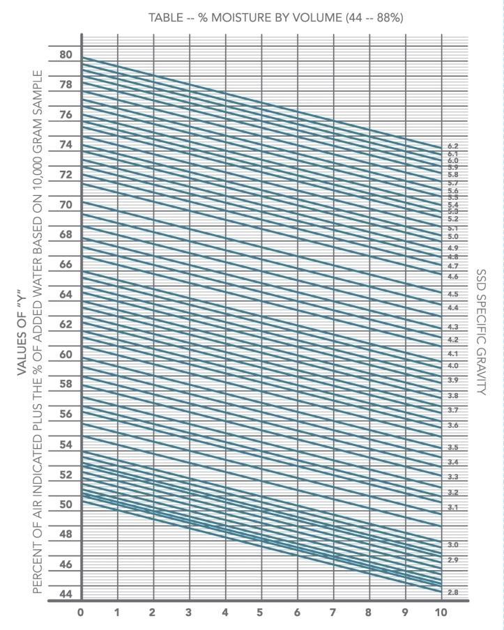
13 4. Is the gauge inaccurate? 5. Is the position of the yellow pointer incorrect? K. If the answer to questions 1 through 5 is "no," the pointer needs to be adjusted. Adjust the pointer as shown in the following examples: 1. If cc of water was removed from the (CT-126A) (see Table 1), but the reading was 4.2% instead of the expected 4%, move the yellow pointer clockwise through an angle equivalent to 0.2% on the scale. 2. If the same amount of water was removed, but the reading was 3.9%, move the yellow pointer counterclockwise through an angle equivalent to 0.1% on the scale. L. The air meter is now calibrated for an air entrainment range close to 4%. VII (CT-126A) AIR METER NOMOGRAPH NOTE: The Nomograph was specially prepared for use with the (CT- 126A), cubic foot Air Meter. Do not attempt to use it with any other meter. V = % = 7169cc A. Procedure to Determine Specific Gravity (See Table 3) 1. Weigh 10,000 grams of material to be tested. (For samples other than 10,000 grams, see step 6.) Put into material container. Note: For specific gravity test, sample must be SSD (Saturated, Surface Dry) for sand and gravel. When testing cement, water should be mixed with cement to avoid trapping or entraining air. This is to prevent the pressure reading from going off the scale when the user tests for remaining air. 11
14 2. Add enough water to nearly fill the material container (see Table 2). Example: 2832 grams of water = 40.0% of material container volume. 3. Clamp lid onto material container, and test for any remaining air in material container and lid. Example: 6.8%. 4. The sum of the percent of water added and the percent of air remaining gives the value of "Y." Example: 40.0% + 6.8% = 46.8%. 5. Follow "Y" line (46.8%) horizontally to the zero moisture line, and read "G" (Moist Sample = GM) from the diagonal lines. Example: 2.59 sp. gr. Note: When testing sand and gravel, reading should be taken immediately after releasing air from air receiver into material container. Some types of sand and gravel will absorb more water than is normal when allowed to stand under pressure in material container. 6. The Nomograph gives readings for 10,000 gram samples only. If a sample other than a 10,000 gram sample (S) is used as S1, determine "Y" as in Step A-1 through A-4 above. To determine specific gravity, follow "Y" line horizontally to zero moisture line. Read figure on the diagonal line, and multiply that reading by S1 to find specific gravity. S Example: If Y = 52.0%, and a different size sample has been used, adjust for use with the Nomograph by the following formula: Example: Y 1 = 52.0 x 9000 = 46.8% 10,000 and G = 2.59 sp.gr. 12
15 B. Procedure to Determine the Percent of Free Moisture by Weight (See Table 3) 1. "G" is known; determine "Y" as before, using steps 1-4 in Section VII-A. NOTE: Do not dry sample to SSD (Saturated, Surface Dry), as is done for specific gravity test. Be sure that the sample of material to be tested is truly a representative sample. Example: For 42.0%--follow this line horizontally to the known SSD specific gravity diagonal line: Read the percent of free moisture by volume, vertically from point of intersection. The percent of free moisture would be 7.8% = M V. To determine M w, multiply M V (7.8%) by Example: 7.8% x = 5.5% M W 2. General Formulas: G or GM = V - Y Mw = G - GM X 100 G - 1 GM VIII. MAINTENANCE A. To assure trouble-free operation, keep meter clean and dry between tests. Clean the meter effectively by either flushing it with a stream of pressurized water or washing it in water, using a brush. DO NOT SUBMERGE THE GAUGE IN WATER. B. Before assembling the meter, remove any sand or grit from underside of material container lid and toggle clamps, in order to prevent damage to lip and clamps. 13
16 C. Leave bleeder valve and both petcocks open when meter is not is use. D. Apply a light, lubricating film of paraffin to the underside of material container lip after every tests. E. When meter is not in use, store it in carrying case. DO NOT STORE METER WITH LID CLAMPED TO MATERIAL CONTAINER. F. Although the surface of the meter may begin to develop a dull appearance after prolonged use, this will not affect its performance. DO NOT ATTEMPT TO POLISH THE METER, as this may cause damage to meter. G. The pressure gauge has an adjustable starting point. If replacing the rubber gasket providing the seal between the lid and the material container becomes necessary, the initial yellow starting point must be set to a new, true starting point. This is required because of the variations in gasket thickness. The following procedure is recommended: 1. Perform Calibration Check Test, as outlined in Section V. 2. If gauge reads less than 1.2%, move the starting point arrow, in a counterclockwise direction, the distance that is equal to the amount the gauge hand is under 1.2%. 3. If gauge reads more than 1.2%, move the starting point arrow, in a clockwise direction, the distance that is equal to the amount the gauge hand is over 1.2%. H. If the pump needs to be cleaned or inspected, use the following procedure to remove it from the air receiver: 1. Unscrew the cap nut and pull the shaft out of the pump body. 2. Use a 10-inch adjustable wrench (preferably in vertical position) to unscrew the pump body and remove it. 14
17 3. When replacing pump into air receiver, use a new gasket seal lubricated with a thin film of grease or heavy oil. 4. Using your fingers, thread pump into air receiver until gasket is touching air chamber. Tighten with a wrench until a good seal is formed. DO NOT OVER TIGHTEN. 5. Periodically clean the carrying case and check for damage. IX. SPECIFICATIONS Capacity 1/4 cu. ft. (0.007 m 3 ) Readings Accuracy Aggregate Size Container Water Initial Pressure Pressure Gauge Tamping Rod Up to 22% entrained air + 1/4% full scale 2" (50.8 mm) maximum With tare weight stamped on bottom; 2-piece clamping device for positive seal 4 oz. required Approximately 10 strokes needed In shockproof mounting Aluminum Dimensions 9-3/4" diam. x 13-1/4" h. (248 x 337) Weight Net 15 lbs. (6.8 kg) 15
18 PARTS LIST Description Part Number Carrying Case Syringe Strike Bar Container Lid Assembly consists of the following items: Main Air Valve Lever Ass'y. consists of the following items: Main Air Valve Stem Rubber Insert O-Ring Lid Gasket Handle Toggle Clamp Assembly consists of the following items: Toggle clamp sub-ass'y (4) Dowel pin 3/16 x 1-1/2 long (2) Groove pin 3/16 x 3/4 long (2) Air Gauge Cushion Gauge Assembly consists of the following items: Gauge (1) Elbow 1/4T x 1/8NPT Elbow 1/4T x 1/4NPT Tubing 5 lg Male Conn 3/16T x 1/8P /12 ( ) (Rev.2) 16
19 Parts List Cont'd. Bleeder Valve Assembly consists of the following items: Cap "O" Ring Elbow Bushing (1) Air Pump /10 ( ) Lid Sub-assembly consists of the following items: Lid Funnel assembly Center cock Nipple
20 TABLE 1 -- PERCENTAGE VALUES 18
21 19
22 Nomograph International 20
23 Nomograph International 21
Tex-416-A, Air Content of Freshly-Mixed Concrete by the Pressure Method
 by the Pressure Method Contents: Section 1 Overview...2 Section 2 Apparatus...3...5 Section 4 Calculations...12 Texas Department of Transportation 1 08/99 06/08 Section 1 Overview Effective dates: August
Tex-414-A, Air Content of Freshly Mixed Concrete by the Volumetric Method
 by the Volumetric Method Contents: Section 1 Overview...2 Section 2 Apparatus...3 Section 3 Sampling Requirements...5 Section 4 Procedures...6 Section 5 Calculation...9 Section 6 Archived Versions...10
AIR CONTENT OF FRESHLY MIXED CONCRETE BY THE PRESSURE METHOD (Kansas Test Method KT-18)
") 5.9.18 AIR CONTENT OF FRESHLY MIXED CONCRETE BY THE PRESSURE METHOD (Kansas Test Method ) 1. SCOPE 1.1. This method of test covers the procedure for determining the air content of freshly mixed concrete
5.9.18 AIR CONTENT OF FRESHLY MIXED CONCRETE BY THE PRESSURE METHOD (Kansas Test Method ) 1. SCOPE 1.1. This method of test covers the procedure for determining the air content of freshly mixed concrete
product manual H-2795 Roll-a-Meter
 11.09 product manual H-2795 Roll-a-Meter Directions The Solution The accuracy of Roll-a-Meter results is not dependent on the correctness of all these factors, but gives directly the percent air in the
Calcimeter Instruction Manual
 Hohner (UK - Canada - Texas) Calcimeter Instruction Manual The Hohner Calcimeter is based on industry standard versions, and is used to measure the calcium carbonate and magnesium carbonate in samples.
OPERATING INSTRUCTIONS
 OPERATING INSTRUCTIONS Air Entrainment Meter ELE International Chartmoor Road, Chartwell Business Park Leighton Buzzard, Bedfordshire, LU7 4WG England phone: +44 (0) 1525 249200 fax: +44 (0) 1525 249249
Assembly Drawing: W-311B-A01, or as applicable Parts List: W-311B-A01-1, or as applicable Special Tools: , , &
 REDQ Regulators Model 411B Barstock Design Powreactor Dome Regulator OPERATION AND MAINTENANCE Contents Scope..............................1 Installation..........................1 General Description....................1
HCMTCB MATERIALS SAMPLING & TESTING PERFORMANCE CHECKLIST
 HCMTCB MATERIALS SAMPLING & TESTING PERFORMANCE CHECKLIST Release Date: January 7, 2014 Sampling Coarse Aggregate PERFORMANCE CHECKLIST AASHTO T-2 Sampling of Aggregates Sampling From A Stockpile 1 When
PAPR Flow Tester. instructions. part no WARNING
 PAPR Flow Tester part no. 488903 instructions WARNING This manual, including warnings and cautions inside, must be carefully read and followed by all persons who use or maintain the product, including
DETERMINING OPTIMUM RESIDUAL ASPHALT CONTENT (RAC) FOR POLYMER-MODIFIED SLURRY SEAL (MICROSURFACING) MIXTURES
 FOR POLYMER-MODIFIED SLURRY SEAL (MICROSURFACING) MIXTURES") Test Procedure for DETERMINING OPTIMUM RESIDUAL ASPHALT CONTENT (RAC) FOR POLYMER-MODIFIED SLURRY SEAL (MICROSURFACING) MIXTURES TxDOT Designation: Tex-240-F Effective Date: December 2004 1. SCOPE 1.1
Test Procedure for DETERMINING OPTIMUM RESIDUAL ASPHALT CONTENT (RAC) FOR POLYMER-MODIFIED SLURRY SEAL (MICROSURFACING) MIXTURES TxDOT Designation: Tex-240-F Effective Date: December 2004 1. SCOPE 1.1
Syringe, Distribution Valve and Infusion Pump Removal/Replacement ATTENTION SYRINGE REPLACEMENT
 ATTENTION SYRINGE REPLACEMENT Please read through the document completely before starting any repairs. Refer to the proper section in the service manual for complete removal and replacement procedures.
8. Carefully layout all the parts of the reservoir setup and clean any dirt, grime or dust from the parts. ( image 8 ) 8
 8") INSTRUCTIONS TO SERVICE AMADAXTREME SHOCKS 2.0 REMOTE RES AUSTRALIAN VERSION PART 1 - SERVICE THE RESERVOIR 1.Prior to cleaning the shock check for any leaks or signs of damage to the res, lines, bushes
INSTRUCTIONS TO SERVICE AMADAXTREME SHOCKS 2.0 REMOTE RES AUSTRALIAN VERSION PART 1 - SERVICE THE RESERVOIR 1.Prior to cleaning the shock check for any leaks or signs of damage to the res, lines, bushes
IMPORTANT SAFETY INSTRUCTIONS READ AND FOLLOW ALL INSTRUCTIONS SAVE THESE INSTRUCTIONS
 Warrior D.E. Filter Operating Procedures IMPORTANT SAFETY INSTRUCTIONS READ AND FOLLOW ALL INSTRUCTIONS SAVE THESE INSTRUCTIONS Table of Contents SECTION I. FILTER INSTALLATION... 1 SECTION II. FILTER
SAILTEC, INC CONGER COURT, OSHKOSH, WI USA
 OK to make this valve hand tight. Pin Mount Style Integral lies 4-5 Degrees above Horizontal. If you store your Hunter "bow down" you will get air-lock in the Integral. Slot Mount Style Pump Body "Down"
Tex-616-J, Construction Fabrics
 Contents: Section 1 Overview... Section s...3 Section 3 Archived Versions...10 Texas Department of Transportation 1 06/00 1/07 Section 1 Overview Effective dates: June 000 December 007. Section 1 Overview
Commonwealth of Pennsylvania PA Test Method No. 742 Department of Transportation October Pages LABORATORY TESTING SECTION. Method of Test for
 Commonwealth of Pennsylvania PA Test Method No. 742 Department of Transportation 14 Pages LABORATORY TESTING SECTION Method of Test for BITUMEN CONTENT OF BITUMINOUS CONCRETE MIXTURES (Pennsylvania Pycnometer
TEST FOR STABILOMETER VALUE OF BITUMINOUS MIXTURES
 Test Procedure for TEST FOR STABILOMETER VALUE OF BITUMINOUS MIXTURES TxDOT Designation: Tex-208-F Effective Date: February 2005 1. SCOPE 1.1 Use this test method to determine the Hveem stability value
Instruction Manual Updated 7/26/2011 Ver. 2.2
 4-Unit Model MB HTHP Filter Press #171-50-4: 115-Volt #171-51-4: 230-Volt Instruction Manual Updated 7/26/2011 Ver. 2.2 OFI Testing Equipment, Inc. 11302 Steeplecrest Dr. Houston, Texas 77065 U.S.A. Tele:
Hydraulic Punch Drivers
 INSTRUCTION MANUAL 7804SB / 7806SB Quick Draw 7704SB / 7706SB Quick Draw Flex 7904SB / 7906SB Quick Draw 90 Quick Draw Hydraulic Punch Drivers Serial Codes AHJ, YZ, and ZA Read and understand all of the
IMPORTANT SAFETY INSTRUCTIONS READ AND FOLLOW ALL INSTRUCTIONS SAVE THESE INSTRUCTIONS
 Commander Cartridge Filter Operating Procedures IMPORTANT SAFETY INSTRUCTIONS READ AND FOLLOW ALL INSTRUCTIONS SAVE THESE INSTRUCTIONS Table of Contents SECTION I. FILTER INSTALLATION... 1 SECTION II.
INSTALLATION INSTRUCTIONS 1/2 THERMOSTATIC VALVE AND TRIM
 INSTALLATION INSTRUCTIONS 1/2 THERMOSTATIC VALVE AND TRIM Valve Model No's: 1-741, 1-742, 1-743, 1-744 1-741 1-742 1-743 1-744 2001 CARNEGIE AVE, SANTA ANA CA 92705 (949) 417-5207 WWW.NEWPORTBRASS.COM
BSA6T and BSA64T Stainless Steel Bellows Sealed Stop Valves Installation and Maintenance Instructions
 1843950/3 IM-P184-03 ST Issue 3 BSA6T and BSA64T Stainless Steel Bellows Sealed Stop Valves Installation and Maintenance Instructions 1. General safety information 2. General product information 3. Installation
State of Nevada Department of Transportation Materials Division METHOD OF TEST FOR DETERMINING THE LIQUID LIMIT OF SOIL
 State of Nevada Department of Transportation Materials Division METHOD OF TEST FOR DETERMINING THE LIQUID LIMIT OF SOIL SCOPE The liquid limit of a soil is that water content, as determined in accordance
Regulator from 1800 B series
 Regulator from 1800 B series Regulator from 1800 B series Measuring of industrial gases frequently requests a precise pressure regulation for the purpose of dosage and proccesing. UNIS FAGAS has two kinds
Exercise 2-3. Flow Rate and Velocity EXERCISE OBJECTIVE C C C
 Exercise 2-3 EXERCISE OBJECTIVE C C C To describe the operation of a flow control valve; To establish the relationship between flow rate and velocity; To operate meter-in, meter-out, and bypass flow control
WW-730. Pressure Sustaining/Relief Control Valve
 WW-730 Pressure Sustaining/Relief Control Valve Installation Operation & Maintenance Page 1 of 6 1. DESCRIPTION The Model 730 Pressure Relief / Sustaining Valve is an automatic control valve designed to
Welker Sampler. Model GSS-1. Installation, Operation, and Maintenance Manual
 Installation, Operation, and Maintenance Manual Welker Sampler Model GSS-1 The information in this manual has been carefully checked for accuracy and is intended to be used as a guide to operations. Correct
1200B2 Series Service Regulators. Instruction Manual
 00B Series Service Regulators Instruction Manual 00B Series Service Regulators 0 Elster American Meter 00B Series Service Regulators General Information The 00B Series Service Regulators are available
1800C and 1800C-HC Series Service Regulators
 1800C and 1800C-HC Series Service Regulators Installation Instructions www.elster-americanmeter.com General Information: The 1800C and 1800C-HC Regulators are available as Full Capacity Internal Relief
ATD LB PRESSURE BLASTER INSTRUCTION MANUAL
 ATD-8402 90LB PRESSURE BLASTER INSTRUCTION MANUAL SAVE THESE INSTRUCTIONS SAFETY INSTRUCTIONS FOR SANDBLASTER 1. Before opening the tank release the air pressure on the sand tank. To do this, turn off
Hydraulic Piston Accumulators
 Ride Control Engineering Services PWCE Extendavator Paul Wever Construction Equipment Co., Inc. P.O. Box 85 401 Martin Drive Goodfield, IL 61742-0085 Phone (309) 965-2005 Fax (309) 965-2905 1-800-990-PWCE
MUELLER GAS. No-Blo Operations Using D-5. Drilling Machine. Reliable Connections. General Information 2
 operating Instructions manual MUELLER GAS TAble of contents PAGE No-Blo Operations Using D-5 General Information 2 Installing No-Blo Service Tees, Service Stop Tees and Curb Stop Tees 3-8 Reconditioning
MAINTENANCE PROCEDURE FOR X 650
 MAINTENANCE PROCEDURE FOR X 650 X 650 25. juli 2005-1/6 MAINTENANCE PROCEDURE FOR X 650 2 ND STAGE WARNING: This maintenance procedure is only for appointed Scubapro technicians that completed a course
Model VR6 System. Installation, Operation & Maintenance
 Model VR6 System Installation, Operation & Maintenance General: All Archer Instruments chlorination systems are carefully designed and tested for years of safe, accurate field service. All Archer Instruments
Halsey Taylor Owners Manual STOP!
 Halsey Taylor Owners Manual 4710 Freeze Resistant Floor Mounted Steel Fountain STOP! PLEASE READ THE FOLLOWING INFORMATION. ITALLATION ITRUCTIO FOR THE 4710FR FTN. WITH 97243C SINGLE VALVE CONTROL ASSEMBLY
TriPod Safety Coupler Installation & Operating Instructions for Models TP4, TP5, TP6, and TP7
 TriPod Safety Coupler Installation & Operating Instructions for Models TP4, TP5, TP6, and TP7 March 2014 Form FVC097 - Rev03 IMPORTANT: KEEP THIS DOCUMENT WITH THE PRODUCT UNTIL IT REACHES THE END USER.
OPERATING INSTRUCTIONS
 OPERATING INSTRUCTIONS Tempe Pressure Cell June 1995 Fig. 1a 1400 Tempe Pressure Cells with 3cm cylinders and 6cm cylinders) mounted on the Tempe Cell Stand Fig. 1b Disassembled 1400 Tempe Pressure Cell
Halsey Taylor Owners Manual 4410 Freeze Resistant Tubular Fountain STOP!
 Halsey Taylor Owners Manual 4410 Freeze Resistant Tubular Fountain STOP! PLEASE READ THE FOLLOWING INFORMATION. ITALLATION ITRUCTIO FOR THE 4410FR FTN. WITH 97243C SINGLE VALVE CONTROL ASSEMBLY ARE LOCATED
Regulators repair and maintenance. XS Compact 2nd stage. January 2014 Rev XSC /3 Ed. C /14 1
 XS Compact 2nd stage January 2014 Rev XSC /3 Ed. C /14 1 XS Compact 2nd stage WARNING! This manual is intended for use by expert technicians who have already received training in equipment repairs and
P5513. Users Manual. Pneumatic Comparison Test Pump. Test Equipment Depot Washington Street Melrose, MA TestEquipmentDepot.
 Test Equipment Depot - 800.517.8431-99 Washington Street Melrose, MA 02176 TestEquipmentDepot.com P5513 Pneumatic Comparison Test Pump Users Manual PN 3963372 November 2010 2010 Fluke Corporation. All
Troyer s Gourd Rack 8 unit F R H O P
 B E A D I M-N L Vertical Parts F R H O P Horizontal Parts C G J Updated 11/16 Parts List A: Top of Pole B: Bottom of Pole C: 48 Ground Stake D: Top Perch rods 48 long E: Hub F: Rope Winder w/ attached
Hydrostatic Pressure Testing
 General An experienced or qualified person will be put in charge of hydro and should meet with the supervisor in charge of the job prior to test. Customer expectations should be clarified prior to beginning
30T A/Manual Hydraulic Shop Press
 30T A/Manual Hydraulic Shop Press Operation Manual 1 1. Important Information 1.1 Safety Information 1.1.1 Hazard Symbols Used in the Manuals This manual includes the hazard symbols defined below when
V5197A. Firing Rate Gas Valve APPLICATION FEATURES PRODUCT HANDBOOK
 V5197A Firing Rate Gas Valve PRODUCT HANDBOOK APPLICATION The V5197A are firing rate valves used to provide variable flow control of air, natural gas, liquefied petroleum (LP), and manufactured gases.
Tex-227-F, Theoretical Maximum Specific Gravity of Bituminous Mixtures
 Gravity of Bituminous Mixtures Overview Effective date: August 1999 to October 2004. Use this method to measure the theoretical maximum specific gravity (commonly referred to as 'Rice' gravity) of a bituminous
TEST SPECIFICATION NYT-909-C
 748 Starbuck Ave, Watertown, NY 13601 Phone: +1-315-786-5200 Engineering Fax: +1-315-786-5673 TEST SPECIFICATION NYT-909-C CODE OF TESTS FOR TESTING "AB" TEST RACK P/N 702546 & 702612 ISSUE NO. 5 1.0 THE
APP pumps APP and APP Disassembling and assembling
 Service guide APP pumps APP 11-13 and APP 16-22 Disassembling and assembling hpp.danfoss.com Table of Contents Contents 1. Introduction... 2 2. Disassembling the pump... 3 3. Assembling the pump... 6 4.
V43 Pressure Actuated Water Regulating Valve
 FANs 125, 121 Product/Technical Bulletin V43 Issue Date 0996 V43 Pressure Actuated Water Regulating Valve The V43 Pressure Actuated Water Regulating Valves are designed to regulate water flow for water-cooled
ASPHALT PLANT LEVEL 1
 ASPHALT PLANT LEVEL 1 Module 6: Maximum Specific Gravity FM 1 T 209 FDOT Course Release: 10, Module 6 1 Specification Year: January 2015 The terms Gmm or Maximum Specific Gravity or Rice gravity are often
MODEL 1329 Tank Gauge
 SERVICE INSTRUCTIONS FOR PETRO-METER 1329 GAUGE SERVICE INSTRUCTIONS MODEL 1329 Tank Gauge www.petro-meter.com Petro-Meter 1329 series Service Instructions HOW TO DETERMINE IF A PETRO-METER IS IN GOOD
Operation & Maintenance Manual Place this manual with valve or person responsible for maintenance of the valve
 Operation & Maintenance Manual Place this manual with valve or person responsible for maintenance of the valve Model CYCLE GARD II, CI & CNA YOUR PRODUCT INFORMATION: Model Number: Date: Serial Number:
LABORATORY TECHNIQUES. Pouring Liquids
 LABORATORY TECHNIQUES Working in the chemistry laboratory you will be handling potentially dangerous substances and performing unfamiliar tasks. This section provides you with a guide to the safe laboratory
Density of Granular Material by Modified Sand-Cone Method for Thin Layers
 Density of Granular Material by Modified Sand-Cone Method for Thin Layers 1. Scope: This test is for determining in-place density of granular materials that have a total thickness of 3 or less. 2. Apparatus:
PRS(TC)4,8 USER MANUAL. Read the complete manual before installing and using the regulator.
4,8 USER MANUAL. Read the complete manual before installing and using the regulator.") PRS(TC)4,8 USER MANUAL Read the complete manual before installing and using the regulator. WARNING INCORRECT OR IMPROPER USE OF THIS PRODUCT CAN CAUSE SERIOUS PERSONAL INJURY AND PROPERTY DAMAGE. Due to
PRS(TC)4,8 USER MANUAL Read the complete manual before installing and using the regulator. WARNING INCORRECT OR IMPROPER USE OF THIS PRODUCT CAN CAUSE SERIOUS PERSONAL INJURY AND PROPERTY DAMAGE. Due to
tel: fax: web:
 Tri-Flex 2 Five-Cell Permeability Test System For high volume commercial laboratory testing, the Tri-Flex 2 Five-Cell Permeability Test System offers the user the capabilities to test up to five samples
08.60 Pycnometer. operating instructions. All it takes for environmental research. Contents
 08.60 Pycnometer operating instructions Contents On these operating instructions...2 1. Introduction...2 2. Principle of the air pycnometer according to Langer...2 3. Applications...2 4. Preparing the
DS06D,G Dial Set Pressure Regulating Valve
 DS06D,G Dial Set Pressure Regulating Valve PRODUCT DATA FEATURES APPLICATION Built-in, factory-calibrated outlet pressure adjustment dial. Noncorroding unitized cartridge contains all working parts and
WW-720. Pressure Reducing Control Valve
 WW-720 Pressure Reducing Control Valve (Size Ranges: 2-4 and 6-14 ) Installation Operation & Maintenance Page 1 of 6 1. DESCRIPTION The Model 720 Pressure Reducing is an automatic control valve (powered
1500g & 3000g Centrifuge Extractors BM050 & BM055. Impact Test Equipment Ltd & User Guide.
 1500g & 3000g Centrifuge Extractors BM050 & BM055 Impact Test Equipment Ltd www.impact-test.co.uk & www.impact-test.com User Guide User Guide Impact Test Equipment Ltd. Building 21 Stevenston Ind. Est.
PyroShot High Speed (HS) Including Long Range and BackFire options Serial Numbers HS-301 and above
 Including Long Range and BackFire options Serial Numbers HS-301 and above") PyroShot High Speed (HS) Including Long Range and BackFire options Serial Numbers HS-301 and above Operators Manual Field Support Services Atlanta, GA pyroshot.com/helifire.com 770-454-1130 25 September
PyroShot High Speed (HS) Including Long Range and BackFire options Serial Numbers HS-301 and above Operators Manual Field Support Services Atlanta, GA pyroshot.com/helifire.com 770-454-1130 25 September
Disassembling and assembling APP and APP 16-22
 MAKING MODERN LIVING POSSIBLE Instruction Disassembling and assembling APP 11-13 and APP 16-22 ro-solutions.com Table of Contents 1. Disassembling...3 2. Disassembling the pump...3 3. Assembling the pump....7
Instruction Manual LIMITED 1 YEAR WARRANTY. Hydraulic Punch Driver Read this material before using this product.
 Instruction Manual Hydraulic Punch Driver 902-483 LIMITED 1 YEAR WARRANTY We make every effort to assure that its products meet high quality and durability standards, and warrant to the original purchaser
Model 23H Hand Crank Seamer
 OPERATOR'S MANUAL Model 23H Hand Crank Seamer If you are not experienced with your seamer, please read and understand this manual before operating the machine. If you have a question discuss it with your
OXYTEMP Instructions 1
 OXYTEMP Instructions 1 Congratulations on purchasing your new OxyTemp Probe! ASSEMBLY INSTRUCTIONS FOR ECO-OXYGEN PROBES 1. Thread the stem into the bottom of the upper housing. 2. Tighten stem with a
Gilson Aqua-Check Moisture Tester MA-26X
 OPERATING MANUAL Gilson Aqua-Check Moisture Tester MA-26X Rev: 01/2019 PHONE: 800-444-1508 P.O. Box 200, Lewis Center, Ohio 43035-0200 740-548-7298 E-mail: customerservice@gilsonco.com Product Web Page:
product manual H-4166 & H-4167 Voluvessel
 11.09 product manual H-4166 & H-4167 Voluvessel this is a blank page corrector This unit has been calibrated and is ready for use as received. After set-up, calibration is recommended. Calibration Check:
12 Saturn Owner s Manual
 12 Saturn Owner s Manual Water Sports Equipment Inflation, set up and supervision must be done by a mature and knowledgeable adult! Inspect product for any unsafe conditions before use! Do not use if repair
Type S301 & S302 Gas Regulators INTRODUCTION INSTALLATION. Scope of Manual. Description. Specifications. Type S301 and S302. Instruction Manual
 Fisher Controls Instruction Manual Type S301 & S302 Gas Regulators October 1981 Form 5180 WARNING Fisher regulators must be installed, operated, and maintained in accordance with federal, state, and local
Bermad Pressure Reducing. Model: 42T
 Bermad Pressure Reducing Pilot Operated Pressure Control Valve Model: 42T Installation Operation Maintenance Manual (IOM) REV. 27.7.17 Page 1 of 12 Safety First BERMAD believes that the safety of personnel
A3S Bellows Sealed Stop Valve Installation and Maintenance Instructions
 1326050/3 IM-P132-11 ST Issue 3 A3S Bellows Sealed Stop Valve Installation and Maintenance Instructions 1 General safety information 2 General product information 3 Installation 4 Commissioning 5 Operation
Constant Pressure Crude Oil Container Model CPCCP
 Installation, Operations, and Maintenance Manual Constant Pressure Crude Oil Container Model CPCCP The information in this manual has been carefully checked for accuracy and is intended to be used as a
OPERATING INSTRUCTIONS
 OPERATING INSTRUCTIONS Combination Permeameter ELE International Chartmoor Road, Chartwell Business Park Leighton Buzzard, Bedfordshire, LU7 4WG England phone: +44 (0) 1525 249200 fax: +44 (0) 1525 249249
OPERATION MANUAL Please read this Operation Manual carefully before use, and file for future reference.
 English Lubrication Free Air Turbine Handpiece with Water Spray OPERATION MANUAL Please read this Operation Manual carefully before use, and file for future reference. OM-T0286E 001 Thank you for purchasing
Product Information News September 26, 2003
 Product Information News September 26, 2003 LEVER HEIGHT INSPECTION FOR FIREHAWK MMR MSA is announcing a revision to the instructions for the Firehawk MMR Second Stage Regulator as they relate to the air
500SE SECOND STAGE SERVICE PROCEDURE
 500SE SECOND STAGE SERVICE PROCEDURE This 500SE Service Procedure conveys a list of components and service procedures that reflect the 500SE as it was configured at the time of this writing. CONTENTS TROUBLESHOOTING...
WW-720. Pressure Reducing Control Valve
 WW-720 Pressure Reducing Control Valve (Size Ranges: 2-4 and 6-14 ) Installation Operation & Maintenance Page 1 of 6 1. DESCRIPTION The Model 720 Pressure Reducing is an automatic control valve (powered
Service and Repair Operative Manual MC9 1 st STAGE. MC9 1 st Stage. 1 st STAGE MC9. Jannuary Rev. MC9 /B Ed. C/13
 MC9 1 st Stage 137 1 st STAGE MC9 Jannuary 2009 - Rev. MC9 /B Ed. C/13 138 WARNING! This manual is intended for use by expert technicians who should attend or have already received training in equipment
Vacuum Pycnometer BM705. Impact Test Equipment Ltd & User Guide. User Guide
 Vacuum Pycnometer BM705 Impact Test Equipment Ltd www.impact-test.co.uk & www.impact-test.com User Guide User Guide Impact Test Equipment Ltd. Building 21 Stevenston Ind. Est. Stevenston Ayrshire KA20
1.0 - OPENING AND CLOSING THE DOOR
 The purpose of this manual is to provide the user with instructions on how to safely open and close, how to conduct routine maintenance, and how to install the PEI TWINLOCK Closure on a pressure vessel.
3M Liqui-Cel EXF-10x28 Series Membrane Contactor
 Membrane Contactors 3M Liqui-Cel EXF-10x28 Series Membrane Contactor Assembly and Disassembly Instructions 3M.com/Liqui-Cel TABLE OF CONTENTS I. Safety and Warning 3 II. Assembly Parts 4 III. Part Orientation
INSTALLATION & START-UP INSTRUCTIONS. Clack WS1 & WS1.25 METER WATER SOFTENER SYSTEMS
 INSTALLATION & START-UP INSTRUCTIONS Clack WS1 & WS1.25 METER WATER SOFTENER SYSTEMS 1999-2009 QualityWaterForLess.com - 1 - info@qualitywaterforless.com Preface: Thank you for your purchase of a new Water
Gas Laws. Introduction
 Gas Laws Introduction In 1662 Robert Boyle found that, at constant temperature, the pressure of a gas and its volume are inversely proportional such that P x V = constant. This relationship is known as
Procedure 85 Attaching The Humidifier To The Oxygen Flow Meter Or Regulator. Procedure 86 Administering Oxygen Through A Nasal Cannula
 Chapter 12 Respiratory Procedures Procedure 81 Checking Capillary Refill Procedure 82 Using A Pulse Oximeter Procedure 83 Preparing Wall-Outlet Oxygen Procedure 84 Preparing The Oxygen Cylinder Procedure
3" UC Ultra-Chuck Durable Lightweight Air Inflated Bladder Chuck Operation/Repair Manual. (76.2 mm) DOUBLE E COMPANY, INC.
 DOUBLE E COMPANY, INC.") 3" UC-3000 (76.2 mm) Ultra-Chuck Durable Lightweight Air Inflated Bladder Chuck Operation/Repair Manual DOUBLE E COMPANY, INC. 319 Manley Street, West Bridgewater, MA 02379 U.S.A. Tel: (508) 588-8099 /
3" UC-3000 (76.2 mm) Ultra-Chuck Durable Lightweight Air Inflated Bladder Chuck Operation/Repair Manual DOUBLE E COMPANY, INC. 319 Manley Street, West Bridgewater, MA 02379 U.S.A. Tel: (508) 588-8099 /
LRS(H)4 Pressure-Reducing Regulator User Manual
4 Pressure-Reducing Regulator User Manual") LRS(H)4 Pressure-Reducing Regulator User Manual Read the complete manual before installing and using the regulator. 2 Safe Product Selection When selecting a product, the total system design must be considered
LRS(H)4 Pressure-Reducing Regulator User Manual Read the complete manual before installing and using the regulator. 2 Safe Product Selection When selecting a product, the total system design must be considered
OPERATING AND MAINTENANCE MANUAL
 Series 4300 Engineered Performance TABLE OF CONTENTS 0 INTRODUCTION 1 1 Scope 1 2 Description 1 3 Specifications 1 0 INSTALLATION 1 1 Mounting 1 2 Piping 1 1 Connecting Process Pressure 2 2 Vent Connections
State of Nevada Department of Transportation Materials Division METHOD OF TEST FOR SAND EQUIVALENT
 State of Nevada Department of Transportation Materials Division METHOD OF TEST FOR SAND EQUIVALENT SCOPE This test method is intended to determine the proportion of detrimental fines (dust or clay size
Maintenance and Repair. AirHawk II Air Mask. Second Stage Regulator. Order No.: /02 Prnt. Spec (I) MSAsafety.
 MSAsafety.") Maintenance and Repair Second Stage Regulator Order No.: 10104241/02 Prnt. Spec. 10000005389(I) MSAsafety.com WARNING! Read this manual carefully before servicing the device. The device will perform as
Maintenance and Repair Second Stage Regulator Order No.: 10104241/02 Prnt. Spec. 10000005389(I) MSAsafety.com WARNING! Read this manual carefully before servicing the device. The device will perform as
MUELLER. A Wall Type. Indicator Post. Reliable Connections. General Information 2. Technical Data/ Dimensions 3. Installation 4-5.
 Installation Instructions manual MUELLER table of contents PAGE A-20814 Wall Type General Information 2 Technical Data/ Dimensions Installation 4-5 Maintenance 6 Parts 7 Indicator Post! WARNING: 1. Read
MUELLER A A Non-Adjustable. Vertical Indicator Posts. Reliable Connections. General Information 2. Technical Data 3.
 Installation Instructions manual MUELLER table of contents PAGE A-20808 General Information 2 Technical Data 3 Dimensions 4 A-20809 Non-Adjustable Installation 5-6 Parts 7 Maintenance 8 Vertical Indicator
Standard Test Method for Air Content of Freshly Mixed Concrete by the Pressure Method 1
 Designation: C 231 03 Standard Test Method for Air Content of Freshly Mixed Concrete by the Pressure Method 1 This standard is issued under the fixed designation C 231; the number immediately following
Oct 1, 2002 LAB MANUAL SPECIFIC GRAVITY & ABSORPTION of FINE AGGREGATE AASHTO Designation T 84 (Mn/DOT Modified)
") Oct 1, 2002 LAB MANUAL 1205.0 1205 SPECFC GRAVTY & ABSORPTON of FNE AGGREGATE AASHTO Designation T 84 (Mn/DOT Modified) 1205.1 GENERAL This test method is intended for use in determining the bulk and apparent
Oct 1, 2002 LAB MANUAL 1205.0 1205 SPECFC GRAVTY & ABSORPTON of FNE AGGREGATE AASHTO Designation T 84 (Mn/DOT Modified) 1205.1 GENERAL This test method is intended for use in determining the bulk and apparent
!!!! SERVICE MANUAL PRESSURE POT 2 GALLON. Service Manual: LT Washington St 931 Progress Ave., #7
 EXEL North America, Inc. EXEL Industrial Canada, Inc. 1310 Washington St 931 Progress Ave., #7 West Chicago, IL 60185 Scarborough ONT, M1G 3V5 Ph : (800) 573 5554 Ph : (800) 450 0655 Fx : (800) 664 1511
PC3_ and PC4_ Pipeline Connectors
 1283050/4 IM-P128-06 ST Issue 4 PC3_ and PC4_ Pipeline Connectors Installation and Maintenance Instructions 1. Safety information 2. Description PC30 shown 3. Installation 4. Welding of pipeline connector
Paddle Bar Replacement
 This procedure is to help facilitate the replacement of the 23 Paddle Bar Assembly on the ANKOM Dietary Fiber Analyzer. Note: The following items will be sent in a replacement package as part of the 23
1. The rate of flow from a well is controlled by surface and bottom-hole. 2. Usually, the rate is changed by adjusting a (surface/ subsurface) choke.
 choke.") UNIT 1 CHOKE SELECTION AND ADJUSTMENT Exhibits 1 through 4 are placed in the center of the book so that they may be removed easily for reference. Please remove them now so that you will have them available
UNIT 1 CHOKE SELECTION AND ADJUSTMENT Exhibits 1 through 4 are placed in the center of the book so that they may be removed easily for reference. Please remove them now so that you will have them available
Attention: This operator's manual should be read carefully before using the pistol! ENGLISH
 Attention: This operator's manual should be read carefully before using the pistol! 03-2003 23 Important measures when using arms: TABLE OF CONTENTS All firearms are dangerous objects, they should be used
VBS-9263 Series. Application. Features. Applicable Literature
 TAC 1354 Clifford Avenue P. O. Box 2940 Loves Park, IL 61132-2940 www.tac.com VBS-9263 Series 1/2" and 3/4" Screwed NPT 316 Stainless Steel Stem Up Closed, Two-Way Valves General Instructions Application
AUTOMATED INDUSTRIAL MACHINE, INC TOGGLE-AIRE
 AUTOMATED INDUSTRIAL MACHINE, INC TOGGLE-AIRE DIVISION Installation, Operation and Maintenance Hydro-Pneumatic Series Bench Presses IMPORTANT It is the responsibility of the employer/purchaser to provide
Florida Method of Test for MEASUREMENT OF WATER PERMEABILITY OF COMPACTED ASPHALT PAVING MIXTURES
 Florida Method of Test for MEASUREMENT OF WATER PERMEABILITY OF COMPACTED ASPHALT PAVING MIXTURES 1. SCOPE Designation: FM 5-565 1.1 This test method covers the laboratory determination of the water conductivity