PO Box 370 Phone: Swansea NSW 2281 Fax: AUSTRALIA Mobile: Web:
|
|
|
- Shawn Lyons
- 5 years ago
- Views:
Transcription


1 EZI-DRY Pty Limited ABN: PO Box 370 Phone: Swansea NSW 2281 Fax: AUSTRALIA Mobile: Web: INSTRUCTION MANUAL Silica Gel Breathers Part #: TMS-10, TMS-15, TMS-20, TMS-25 6
2 WARNING The EZI-DRY Silica Gel breathers are designed to be installed on electrical transformers. This work environment is hazardous and correct safety procedures should be in place and adhered to before attempting to install or remove these breathers. These instructions should be read in conjunction with any local safety regulations and work procedures. These instructions are only to be used for the correct installation, dismantling and assembly of the EZI-DRY breather. The silica gel in these breathers requires specific personal protective equipment to be used when dismantling and handling the contents. Consult the appropriate MSDS before dismantling. EZI-DRY Pty Ltd can recoend a suitable breather size for the required oil content but the purchaser should make their own determination for correct sizing. The use of these breathers outside these instruction guidelines may cause injury to personnel and/or damage to the equipment it is attached too. Please consult EZI-DRY Pty Ltd if these breathers are to be used in a manner outside these guidelines. 1
3 TABLE OF CONTENTS WARNING... 1 INSTALLING and REMOVAL INSTRUCTIONS... 3 Installing... 3 Removal... 3 DISMANTLING and ASSEMBLY... 4 Dismantling... 4 Assembly... 6 SPECIFICATIONS... 7 Table 1. Large Breather Specifications... 7 Table 2. Adaptor... 8 DESIGN INFORMATION... 8 Table 3. Air Flow Pressure Tests... 8 SIZING


 or stainless steel depending on requirements. These fittings are manufactured to fit a ¾ BSP breather pipe.")
4 INSTALLING AND REMOVAL INSTRUCTIONS CAUTION. These units are designed to mount onto electrical transformers. Dangerous voltages May be present in the vicinity of the mounting point. Ensure all local safety procedures and statutory regulations are carried out, prior to mounting and/or removal of breather and parts. These instructions are suitable for all of these models, TMS-10, TMS-15, TMS-20 and TMS-25. All models are similar in design, the length and number of separation discs is the only variance from unit to unit. (See Table 1) The breathers have been designed to mount into the adaptor (quick connect fitting Picture 1 & 2) which is supplied with each unit. The adaptor may be manufactured from acetyl plastic (standard on all units) or stainless steel depending on requirements. These fittings are manufactured to fit a ¾ BSP breather pipe. (1 BSP are available) The adaptor should be fitted onto the correct breather pipe on the transformer. Thread tape or sealer may be required to ensure no leakage occurs. Tighten adaptor until it is seated (approx 16 onto thread) Do not over tighten as this may damage the adaptor. Picture 1 Acetyl Adaptor Picture 2 Stainless Steel Adaptor Installing The breather unit is now ready to mount. The adaptor has a seating washer inside for correct sealing. Screw the breather into the adaptor and rotate anti-clockwise approx 1 ¼ turns until you can feel the breather male fitting meet the sealing washer. The breather is now installed. No further installation procedures are required. Removal The removal of the breather only requires the clockwise rotation of the breather in the adaptor. When removing, be sure to hold the weight of the breather by placing a hand under the base when rotating clockwise to ensure the secure removal without dropping. 3
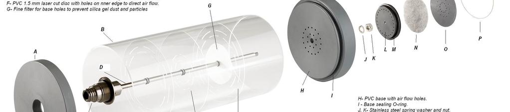
5 DISMANTLING AND ASSEMBLY Dismantling The dismantling will require an area that is clean and tidy, preferably on a work bench at the correct working height. Use some form of blocking (approx 40 in height) so that the breather can be placed upside down onto the blocking and the male screw fitting is clear of the bench top and provides a flat stable area for the breather to sit on. Ensure that the work is carried out over a large containment vessel in case the silica gel is accidentally spilled. At this stage it would be a good idea to measure the distance between the separation discs so as to have an idea of placement when re-filling. Full dismantling should now be done in conjunction with Picture Remove stainless steel circlip from base (item P). 2. Remove black disc by placing a wire in one of the holes to remove (item O). 3. Remove filter pad and replace if contaminated (item N). 4. Remove valve system by using pliers to clamp one of the wings to pull out. Check O-ring on the valve and replace in required (items L & M). 5. Remove the base by placing both hands on either side of the Plexiglas tube and push up with your thumbs (item H) ensuring you maintain firm pressure on the Plexiglas with both your hands. It may require a tap with a rubber mallet on the lip if this does not work. Ensure the breather Plexiglas is held firmly in some manner when doing this. 6. Remove the fine white filter material and check for contamination. Replace if required. (item G) 7. The silica gel can now be emptied into a container. Ensure you have a large enough container to work over as the Plexiglas tube can now come out of the head and spill silica gel everywhere. The separation discs should come out with the weight of the silica gel. 8. Remove the Plexiglas tube and clean as required. The Plexiglas tube can be cleaned with Methylated spirits or Turpentine. Use a non abrasive cloth. Do not use thinners or petroleum products as they could damage the Plexiglas. (Always test cleaner on a small section of Plexiglas prior to use) 9. Check O-ring in the head piece and clean or replace if necessary. All O-rings should be cleaned and re-coated with a suitable silicon grease or lubricant before assembly. 4
6
 into head piece. The Plexiglas tube is only sitting loosely in the head while filling. Always hold down Plexiglas when filling with the silica gel. 3.")

 in place without O-ring ( item I) to test for required gap.")
7 DISMANTLING AND ASSEMBLY Assembly 1. The head piece (item A) should be placed on the stable blocking material and the O-ring placed into position. 2. Place cleaned Plexiglas tube (item B) into head piece. The Plexiglas tube is only sitting loosely in the head while filling. Always hold down Plexiglas when filling with the silica gel. 3. Fill the first section with silica gel. Use measurements obtained prior to dismantling or refer to Table Insert the disc which has the vent holes in the outer edge (item E) in place. 5. Fill the second section. Insert the inner hole disc and continue to follow this sequence and using the correct number of discs (Table1) alternating from outer hole disc to inner hole disc until the silica gel is approximately 15 from the top of the Plexiglas. This allows room to tighten down base to required position. Temporarily place base (item H) in place without O-ring ( item I) to test for required gap. Remove base and replace O-ring. 6. Place fine white filter on shaft and then place base into position. Gently tap down the base so that the Plexiglas is in position and over the sealing O-ring. (item I) The base should now be hard up against the Plexiglas tube. 7. Tighten down base with the stainless steel spring washer in place and the 10 nut (item K, J). Do not over tighten. Nut should be close to flush with top of 10 shaft (item D) 8. Install valve system with o-ring in place (item L, M) 9. Install filter pad. Replace if contaminated (item M) 10. Place black disc with holes in centre into position (item O) 11. Place stainless steel circlip in place (item P) The breather is now ready for mounting. 6

8 Table 1. Large Breather Specifications Part # Silica Gel Content kg Dimension A SPECIFICATIONS Dimension B Dimension C Separators D # Separator Spacing TMS TMS TMS TMS

9 SPECIFICATIONS Table 2. Adaptor Part # Dimension A Dimension B TMS ¾ Thread Size C inch DESIGN INFORMATION These re-chargeable breathers have been designed with a reed valve system in place of the typical oil bath system. The reeds are designed to operate under normal air flow conditions generated by the expansion and contraction of the transformer oil within the transformer. Typical operation of the reed valve is <2 kpa. Each breather is pressurised to 10 kpa and tested for leakage prior to dispatch. (See Table 1 for typical airflow and pressure) TABLE 3. AIR FLOW PRESSURE TESTS Product Flow Rate Pressure ID L/min kpa TMS-10 TMS-15 TMS-20 TMS <1 50 <3 20 < <3 20 <2 50 <4 20 <2 50 <5 These test results may not be indicative of the breather that is purchased as settling of the silica gel in transport can cause further compaction which may alter these results. This testing was carried out in a workshop environment with a Key Instruments Flow meter & pressure gauge at 21 C. 8
10 SIZING There is no standard for the selection of silica gel quantity to oil quantity. Most manufacturers use approximately 1kg /3000 litres of oil. The design of the EZI-DRY breathers and in field testing combined with evidence has shown that the size of the EZI-DRY breather (silica gel quantity) can be reduced by up to 50% when compared to the standard oil bath breather with the same silica gel quantity. There are many factors which can affect the size selection for a transformer, some being: Maintenance inspection intervals. Local environmental conditions.(temperature range, rainfall, humidity) Transformer loading characteristics (oil temperature range/duration). Oil content (in relation to expansion and contraction quantities with temperature changes). When selecting the Silica gel breather size for your transformer, all of these factors should be considered and combined with any other relevant site conditions. EZI-DRY Pty Ltd can suggest a particular size breather, but the purchaser and installer must take the responsibility for correctly sizing the breather. 9
EZI-DRY Pty Limited ABN:
 EZI-DRY Pty Limited ABN: 98 114 507 443 PO Box 370 Phone: 02 49711993 Swansea NSW 2281 Fax: 02 49716320 Mobile: 0427587900 Email: ezidry@exemail.com.au 1. Breather operation Why EZI-DRY Breathers? Most
HYQUEST SOLUTIONS PTY LTD INSTRUCTION MANUAL TIPPING BUCKET RAIN GAUGE MODEL TB6
 INSTRUCTION MANUAL TIPPING BUCKET RAIN GAUGE MODEL TB6 QUALITY SYSTEM ISO:9001 CERTIFIED HYQUEST SOLUTIONS PTY LTD PO BOX 332, LIVERPOOL B.C NSW 1871, AUSTRALIA Phone:(Int.) 612 9601 2022 Fax: :(Int.)
INSTRUCTION MANUAL TIPPING BUCKET RAIN GAUGE. MODEL TB3/0.1mm
 INSTRUCTION MANUAL TIPPING BUCKET RAIN GAUGE MODEL TB3/0.1mm QUALITY SYSTEM ISO 9001 2008 CERTIFIED HYQUEST SOLUTIONS PTY LTD PO BOX 332, LIVERPOOL B.C NSW 1871, AUSTRALIA Phone:(Int.) 612 9601 2022 Fax:
Type BBS-03, BBS-05, BBS-06, BBS-25
 Type BBS-03, BBS-05, BBS-06, BBS-25 Sterile connection elements Sterile Verbindungselemente Raccords union stériles Operating Instructions Bedienungsanleitung Manuel d utilisation 1. THE OPERATING INSTRUCTIONS
INSTRUCTION MANUAL TIPPING BUCKET RAINGAUGE MODEL TB305-1MM
 HYDROLOGICAL SEVICES PTY LTD INSTRUCTION MANUAL TIPPING BUCKET RAINGAUGE MODEL TB305-1MM QUALITY SYSTEM ISO 9001 2008 CERTIFIED HYDROLOGICAL SERVICES PTY LTD PO BOX 332, LIVERPOOL B.C NSW 1871, AUSTRALIA
Reduce pressure zone device suitable for high and medium hazard rated applications Flanged end connections
 VALVCHEQ Backflow Preventers Reduce pressure zone device suitable for high and medium hazard rated applications Flanged end connections Features General application The RP03 provides protection from both
MAINTENANCE PROCEDURE FOR X 650
 MAINTENANCE PROCEDURE FOR X 650 X 650 25. juli 2005-1/6 MAINTENANCE PROCEDURE FOR X 650 2 ND STAGE WARNING: This maintenance procedure is only for appointed Scubapro technicians that completed a course
Rada-Presto TF2020 and TF2020S
 Rada-Presto TF2020 and TF2020S PRODUCT MANUAL IMPORTANT Installer: This Manual is the property of the customer and must be retained with the product for maintenance and operational purposes. 1 INDEX Page
APP pumps APP and APP Disassembling and assembling
 Service guide APP pumps APP 11-13 and APP 16-22 Disassembling and assembling hpp.danfoss.com Table of Contents Contents 1. Introduction... 2 2. Disassembling the pump... 3 3. Assembling the pump... 6 4.
VALVCHEQ BACKFLOW PREVENTERS FIGURE RP03
 Reduce pressure zone device suitable for high and medium hazard rated applications Flanged end connections FEATURES GENERAL APPLICATION The RP03 provides protection from both backsiphonage and backpressure
THE HF-300 SERIES. Operating and Service Manual. Series includes all variants of HF-300/301
 THE HF-300 SERIES Operating and Service Manual Series includes all variants of HF-300/301 Issue A July 2015 1 TABLE OF CONTENTS 1. Description... 3 2. Installation... 3 3. Operation... 4 3.1. Spring Loaded...
12S 1st Stage. -Maintenance Procedure-
 12S 1st Stage -Maintenance Procedure- 1 Warning! All maintenance and repair procedures MUST be performed by a Mares authorized Service Center and/or Distributor. Therefore, the information provided below
LIQUIP DRYBREAK COUPLER. API800 Series MAINTENANCE INSTRUCTIONS
 LIQUIP DRYBREAK COUPLER API800 Series MAINTENANCE INSTRUCTIONS API LOADING COUPLER TO API RP1004 June 2015 Issue: F M:\Product-Info\API8xx\6-Service-Maintenance\API800 MAINTENANCE INSTRUCTIONS 40183.doc
INSTRUCTION MANUAL TIPPING BUCKET RAINGAUGE MODEL TB3
 INSTRUCTION MANUAL TIPPING BUCKET RAINGAUGE MODEL TB3 QUALITY SYSTEM ISO:9001 CERTIFIED HYQUEST SOLUTIONS PTY LTD PO BOX 332, LIVERPOOL B.C NSW 1871, AUSTRALIA Phone:(Int.) 612 9601 2022 Fax: :(Int.) 612
Crosby style JCE Safety Valve Installation, Maintenance and Adjustment Instructions CROSBY
 CROSBY Table of contents 1. Installation 1 1.1. Drainage 1 1.2. Discharge pipework 1 1.3. Preparation for installation 1 2. Pressure adjustment 1 3. Maintenance 1 4. Dismantling 1 4.1. All valve types
Pressure Dump Valve Service Kit for Series 2300 Units
 Instruction Sheet Pressure Dump Valve Service Kit for Series 00 Units. Overview The Nordson pressure dump valve is used to relieve hydraulic pressure instantly in Series 00 applicator tanks when the unit
PRESSURISED PAINT CONTAINER
 PRESSURISED PAINT CONTAINER MODEL NO: CPP2B PART NO: 3082115 OPERATION & MAINTENANCE INSTRUCTIONS GC0913 INTRODUCTION Thank you for purchasing this CLARKE Pressurised Paint Container. Before attempting
INSTALLATION INSTRUCTIONS. CVS 67CFR Pressure Reducing Instrument Supply Regulator INTRODUCTION
 INSTALLATION INSTRUCTIONS CVS 67CFR Pressure Reducing Instrument Supply Regulator INTRODUCTION The CVS Controls 67CFR Filter regulator is a pressure reducing supply regulator typically used for pneumatic
1. CONDITIONS FOR USE 2. SAFETY
 1. CONDITIONS FOR USE This micro abrasive blaster may only be operated: Indoors; Below 6500 ft above sea level altitude; Ambient air temperature between 40-105 F (5-40 C); Maximum relative humidity of
MODEL 200 KNIFE GATE VALVES INSTALLATION & MAINTENANCE MANUAL
 MODEL 200 KNIFE GATE VALVES INSTALLATION & MAINTENANCE MANUAL Index 1. List of components / General arrangement 2. Description 3. Handling 4. Installation 5. Actuators / Operation 6. Maintenance a. Changing
ATS430 turbidity sensor Retractable insertion assembly
 A MEASUREMENT & ANALYTICS INSTRUCTION ATS430 turbidity sensor Retractable insertion assembly Measurement made easy 1 Introduction This publication details installation procedures for the retractable insertion
HYQUEST SOLUTIONS PTY LTD INSTRUCTION MANUAL TIPPING BUCKET RAINGAUGE MODEL TB6
 INSTRUTION MANUAL TIPPING BUKET RAINGAUGE MODEL TB6 QUALITY SYSTEM ISO:9001 ERTIFIED HYQUEST SOLUTIONS PTY LTD PO BOX 332, LIVERPOOL B. NSW 1871, AUSTRALIA Phone:(Int.) 612 9601 2022 Fax: :(Int.) 612 9602
AIR COMPRESSOR OPERATION & MAINTENANCE INSTRUCTIONS MODEL NO: CHAMP 3 PART NO: LS0115
 AIR COMPRESSOR MODEL NO: CHAMP 3 PART NO: 2225222 OPERATION & MAINTENANCE INSTRUCTIONS LS0115 INTRODUCTION Thank you for purchasing this CLARKE Air Compressor. Please read this manual fully before use
REPLACING THE FRONT RIM OF CROSSMAX SLR DISC, CROSSMAX SL DISC 07 AND CROSSMAX ST DISC WHEELS
 022 TECHNICALMANUAL07 WHEEL BUILDING REPLACING THE FRONT RIM OF CROSSMAX SLR DISC, CROSSMAX SL DISC 07 AND CROSSMAX ST DISC WHEELS 1 spoke wrench M40652 1 spoke wrench for aerodynamic spokes M40567 (for
HYQUEST SOLUTIONS PTY LTD INSTRUCTION MANUAL TIPPING BUCKET RAIN GAUGE MODEL TB4
 INSTRUTION MANUAL TIPPING BUKET RAIN GAUGE MODEL TB4 QUALITY SYSTEM ISO:9001 ERTIFIED HYQUEST SOLUTIONS PTY LTD PO BOX 332, LIVERPOOL B. NSW 1871, AUSTRALIA Phone:(Int.) 612 9601 2022 Fax: :(Int.) 612
Supplementary Operation, Assembly, Maintenance Manual for F3-42 model and optional attachments
 FERMENATOR TM Supplementary Operation, Assembly, Maintenance Manual for F3-42 model and optional attachments Congratulations on your purchase, and thank you for selecting the Fermenator TM stainless conical
BP48-1 AND SSP48-1 IN-GROUND POST INSTALLATION INSTRUCTIONS
 BP48-1 AND SSP48-1 IN-GROUND POST INSTALLATION INSTRUCTIONS WARNING: THIS IN-GROUND POST IS NOT DESIGNED FOR USE WITH AN LP GAS CYLINDER. WARNING: SEE YOUR GRILL OWNER S MANUAL FOR PROPER LOCATION, MINIMUM
THE MF-400 SERIES. Operating and Service Manual. Series includes all variants of MF-400/401
 THE MF-400 SERIES Operating and Service Manual Series includes all variants of MF-400/401 Issue A October 2013 1 TABLE OF CONTENTS 1. Description... 3 2. Installation... 3 3. Operation... 4 4. Special
BPB26-1 AND SSPB26-1 PATIO BASE INSTALLATION INSTRUCTIONS
 BPB26-1 AND SSPB26-1 PATIO BASE INSTALLATION INSTRUCTIONS WARNING: THIS PATIO BASE IS NOT DESIGNED FOR USE WITH AN LP GAS CYLINDER. WARNING: SEE YOUR GRILL OWNER'S MANUAL FOR PROPER LOCATION, MINIMUM CLEARANCES,
Maximum 0.85 MPa pressure setting Long-life, high flow perfect for balancer applications
 Outstanding performance in extremely low pressure and low pressure ranges from 0.003 to. Realizing high performance, energy saving, and compact size. Realize precise pressure control in a pressure range
System Pressure Manager Standard & System Pressure Manager Plus
 System Pressure Manager Standard & System Pressure Manager Plus Installation, Commissioning & Servicing Instructions Note: THESE INSTRUCTIONS MUST BE READ AND UNDERSTOOD BEFORE INSTALLING, COMMISSIONING,
Disassembling and assembling APP and APP 16-22
 MAKING MODERN LIVING POSSIBLE Instruction Disassembling and assembling APP 11-13 and APP 16-22 ro-solutions.com Table of Contents 1. Disassembling...3 2. Disassembling the pump...3 3. Assembling the pump....7
Inflatable Packer Single & Double. Single & Double Packer Dimension. Wireline Packer. Water Testing Packer (WTP) Packer
 Packer") Inflatable Packer Single & Double Single & Double Packer Dimension Wireline Packer Water Testing Packer (WTP) Packer Packer Working Pressure & Depth Chart Packer Water Hand Pump Packer Air Driven Pump
Inflatable Packer Single & Double Single & Double Packer Dimension Wireline Packer Water Testing Packer (WTP) Packer Packer Working Pressure & Depth Chart Packer Water Hand Pump Packer Air Driven Pump
FOR INSTALLING CO 2 BLENDER KIT (P/N IN BEER SYSTEM
 IMI CORNELIUS INC One Cornelius Place Anoka, MN 55303-623 Telephone (800) 238-3600 Facsimile (612) 22-326 INSTALLATION INSTRUCTIONS FOR INSTALLING CO 2 BLENDER KIT (P/N 111612000 IN BEER SYSTEM SECONDARY
Syringe, Distribution Valve and Infusion Pump Removal/Replacement ATTENTION SYRINGE REPLACEMENT
 ATTENTION SYRINGE REPLACEMENT Please read through the document completely before starting any repairs. Refer to the proper section in the service manual for complete removal and replacement procedures.
Pressure Dump Valve Service Kit for Series 3000 Units
 Instruction Sheet Pressure Dump Valve Service Kit for Series 000 Units. Overview The Nordson pressure dump valve is used to relieve hydraulic pressure instantly in Series 00, 400, 500, and 700 applicator
SEries 29 Hydrant valves installation, operation & maintenance manual
 Instruction for use Thank you for selecting an AVK product. With correct use, it will give long and reliable service. This manual has been prepared to assist you install, operate and maintain the valve
HOME ASSEMBLY INSTRUCTIONS
 HOME ASSEMBLY INSTRUCTIONS This Papillionaire Bicycle now belongs to you. It will take you to work, wait patiently outside your local cafe, and carry your groceries home. This is the start of your long-term
Discontinued. Powers Controls. Technical Instructions Document No P25 RV Rev. 1, May, RV 201 Pressure Reducing Valves.
 Powers Controls RV 201 Pressure Reducing Valves Description Features Product Numbers Dual Pressure PRV Technical Instructions Document No. 155-049P25 RV 201-1 Single Pressure PRV The RV 201 Pressure Reducing
Auto-Rewind Hose Reels INSTRUCTION MANUAL FOR OXY-LPG MODEL
 Auto-Rewind Hose Reels INSTRUCTION MANUAL FOR OXY-LPG MODEL Introduction Thank you for purchasing a Retracta Auto Rewind Hose Reel. The Retracta range of hose reels are a breakthrough in industrial quality
24L AIR COMPRESSOR MODEL NO: TIGER 8/260 PART NO:
 24L AIR COMPRESSOR MODEL NO: TIGER 8/260 PART NO: 1499490 OPERATION & MAINTENANCE INSTRUCTIONS ORIGINAL INSTRUCTIONS LS0918 - ISS 2 INTRODUCTION Before attempting to use this product, please read this
VULCAN GAS SALAMANDER MODEL SG-G
 VULCAN GAS SALAMANDER MODEL SG-G Index: General Data 2 Owners Responsibility 3 Authorised Vulcan Catering Equipment Branches And Dealers 3 Parts Ordering / Service Information 4 Prior to Installation Of
M03 WUNDATRADE. Heat Pump Manifold. Before you start: Check the contents. Optional. ...a division of WUNDA GROUP PLC
 Before you start: Check the manifold box contents against the list below. Check the contents Flow gauges 1. Bar assembly with manual return valves 2. 2 x Auto air vent & drain hose attachments Optional
HORNE 20 THERMOSTATIC MIXING VALVE TYPE H-2003
 PO Box 7, Rankine Street Johnstone, Renfrewshire Scotland. PA5 8BD Tel: 01505 321 455 Fax: 01505 336 287 Email: technical@horne.co.uk Web: www.horne.co.uk HORNE 20 THERMOSTATIC MIXING VALVE TYPE H-2003
WALL MOUNTED EMERGENCY EYE & EYE/FACE WASH HAND OPERATED
 WALL MOUNTED EMERGENCY EYE & EYE/FACE WASH HAND OPERATED Installation, Operating & Maintenance Instructions EEE120 EFE300 I00097_Oct 17 NOTE: THIS DOCUMENT IS TO BE LEFT ONSITE WITH FACILITY MANAGER AFTER
Summary of Accumulators These operating instructions apply to the accumulators listed in the table shown below.
 Page 1 of 15 Summary of Accumulators These operating instructions apply to the accumulators listed in the table shown below. Model Number A25-XXXX-3.6K Series A40-XXXX-3K Series A40X-XXXX-3.6K Series A60-XXXX-3K
RG1200 Service and Repair Manual
 Dive Rite RG 1200 Regulator Service and Repair Manual Page 1 Text and Photography by Pete Nawrocky Copyright ( ) 1999-2000, Lamartek, Inc., dba Dive Rite RG1200 Service and Repair Manual First Stage.........................................
ROTATING DISK VALVES INSTALLATION AND MAINTENANCE 1. SCOPE 3 2. INFORMATION ON USAGE 3 3. VALVE TYPES 3 4. OPERATORS 5 5. VALVE CONSTRUCTION 6
 Sub Section INDEX Page Number 1. SCOPE 3 2. INFORMATION ON USAGE 3 3. VALVE TYPES 3 4. OPERATORS 5 5. VALVE CONSTRUCTION 6 6. INSTALLATION AND OPERATION 6 7. MAINTENANCE 8 8. REPAIR 9 9. ASSEMBLY 10 10.
3M Liqui-Cel EXF-10x28 Series Membrane Contactor with ANSI or JIS Connections with Integrated End Caps
 Membrane Contactors 3M Liqui-Cel EXF-10x28 Series Membrane Contactor with ANSI or JIS Connections with Integrated End Caps Assembly and Disassembly Instructions 3M.com/Liqui-Cel TABLE OF CONTENTS I. Safety
Training. Testor Training Manual
 Training Testor Training Manual Index Section 1 Introduction and Safety Warnings Section 2 Test Procedures Section 3 Test Hoses Section 4 Fault Location 1:1 1.1 Introduction The Dräger Testor test equipment
HYDRAULIC MOBILE LIFTING TABLE
 HYDRAULIC MOBILE LIFTING TABLE MODEL NO: HTL300 & HTL500 PART NO: 7610148 & 76210152 OPERATION & MAINTENANCE INSTRUCTIONS ORIGINAL INSTRUCTIONS GC1116 INTRODUCTION Thank you for purchasing this CLARKE
Encore PE 50-lb Feed Hopper
 Instruction Sheet P/N 160429-01 Encore PE 50-lb Feed Hopper WARNING: Allow only qualified personnel to perform the following tasks. Follow the safety instructions in this document and all other related
Rocky Mountain Instinct / Pipeline Alloy Frame Assembly Guide. Date: April 7, 2017
 Rocky Mountain Instinct / Pipeline Alloy Frame Assembly Guide Date: April 7, 2017 1 Table of Contents Front Triangle Preparation... 4 Parts Needed... 4 Instructions... 4 Chain Stay Preparation... 6 Parts
Training. tm PA90 Series - Lung Demand Valve
 D Training Dräger tm12842 PA90 Series - Lung Demand Valve Index Section 1 Instructions for Use Section 2 Introduction and Safety Warnings Section 3 Product Description Section 4 Operating Principle Section
Two-stage valve type NE
 Two-stage valve type NE Product documentation Operating pressure pmax: Flow rate Qmax: 700 bar (High pressure) 80 bar (Low pressure) 25 lpm (High pressure) 180 lpm (Low pressure) D 7161 03-2017-1.0 by
Booster Pump PB4-60 Replacement Kits
 Booster Pump PB4-60 Replacement Kits FOR YOUR SAFETY - This product must be installed and serviced by a contractor who is licensed and qualified in pool equipment by the jurisdiction in which the product
Final Assembly Instructions Bikes with 16 Wheel Size
 Final Assembly Instructions Bikes with 16 Wheel Size Thank you for buying your new bicycle from L.L.Bean. Read these instructions carefully before beginning the final assembly. Prior to shipping, our expert
15ME-014 INSTRUCTION MANUAL OF STERN TUBE SEALING TYPE EVK2RV. URL
 15ME-014 E INSTRUCTION MANUAL OF STERN TUBE SEALING TYPE EVK2RV URL http://www.kemel.com CONTENTS [A] Installation [B] Piping [C] Inspection [D] Handling [E] Parts replacement intervals [F] Handling check
Parts List. 7. Handlebars 8. Grips 9. Handlebar Stem 10. Front Brake 11. Front Wheel 12. Crank 13. Chain
 Woodworm Cruise Parts List 1. Free Wheel with Rear Hub 2. Fenders 3. Fender Stay 4. Quick Release 5. Saddle 6. Seat Post 7. Handlebars 8. Grips 9. Handlebar Stem 10. Front Brake 11. Front Wheel 12. Crank
INSTRUCTION MANUAL. January 23, 2003, Revision 0
 INSTRUCTION MANUAL Model 810A In-Vitro Test Apparatus for 310B Muscle Lever January 23, 2003, Revision 0 Copyright 2003 Aurora Scientific Inc. Aurora Scientific Inc. 360 Industrial Parkway S., Unit 4 Aurora,
EVO Solid Downtube. Operators Manual for Downtubes fitted with zinc plated springs June 2004
 EVO Solid Downtube Operators Manual for Downtubes fitted with zinc plated springs June 2004 Read this manual fully before operating the EVO Solid Downtube For all EVO Shearing Plants Head Office 46 Miguel
KTM OM-2 SPLIT BODY FLOATING BALL VALVES INSTALLATION AND MAINTENANCE INSTRUCTIONS
 Before installation these instructions must be fully read and understood SECTION 1 - STORAGE 1.1 Preparation and preservation for storage All valves should be properly packed in order to protect the parts
UNITY 2. Uni-DAAMS Manual. Version 1.3 (Changes to Section 1.1) March 2010
 March 2010") UNITY 2 Uni-DAAMS Manual Version 1.3 (Changes to Section 1.1) March 2010 1. Introduction...2 1.1. Installing the DAAMS tube ovens...2 1.2. Swapping between tube types...5 1.3. Changing tube oven o-rings...6
UNITY 2 Uni-DAAMS Manual Version 1.3 (Changes to Section 1.1) March 2010 1. Introduction...2 1.1. Installing the DAAMS tube ovens...2 1.2. Swapping between tube types...5 1.3. Changing tube oven o-rings...6
100L AIR COMPRESSOR MODEL NO: TIGER 16/1010 PART NO: OPERATION & MAINTENANCE INSTRUCTIONS LS01/13
 100L AIR COMPRESSOR MODEL NO: TIGER 16/1010 PART NO: 2244025 OPERATION & MAINTENANCE INSTRUCTIONS LS01/13 INTRODUCTION Thank you for purchasing this product. Before attempting to use this product, please
Reduce pressure zone device suitable for high and medium hazard rated applications BSP screwed connections
 Reduce pressure zone device suitable for high and medium hazard rated applications BSP screwed connections Features General application The RP03 provides protection from both backsiphonage and backpressure
Service and Repair Manual
 II stage R2 Ice/ Special, II stage R 1 Pro DOWNSTREAM 2 nd STAGE REGULATOR Service and Repair Manual Introduction Safety Precautions...4 General Procedures, Maintenance Schedules...5 Initial Inspection
UltRo Dual Flow Reverse Osmosis Water System
 UltRo Dual Flow Reverse Osmosis Water System Congratulations on this great investment to your health. **IMPORTANT NOTE BEFORE YOU BEGIN** We recommend you call your local friendly plumber to ensure proper
bathrooms.com Concentric Thermostatic Shower Mixers Cleaning and Care Installation Manual Contents
 bathrooms.com Concentric Thermostatic Shower Mixers Contents Page 3 - General Information & Safety Page 4 - Installation Page 5 - Concentric Valve Set-up Page 6 - Exposed fitting of Concentric Mixer Valves
DelVal Flow Controls Private limited
 DelVal Flow Controls Private limited (A DIVISION OF DelTech CONTROLS LLC, USA) DelVal Series 50/5, 5A/5B Butterfly Valves INSTALLATION, OPERATION AND MAINTENANCE MANUAL ENGINEERING DATA SHEET E.D.S. NO
Replacement of Interchangeable Membrane
 Replacement of Interchangeable Membrane Replacement of Expansion Vessel Membrane 100+ Capacity 1. Firstly, before disconnecting the vessel, bear in mind that you must isolate the vessel from the system
LIQUIP DRYBREAK COUPLER. LYNX Series MAINTENANCE INSTRUCTIONS
 LIQUIP DRYBREAK COUPLER LYNX Series MAINTENANCE INSTRUCTIONS API LOADING COUPLER TO API RP1004 February 2016 Issue: DRAFT A Issue: DRAFT - A 02/01/16 Page 1 CONTENTS LYNX Series Datasheet... 3 LYNX Series
24L AIR COMPRESSOR OPERATION & MAINTENANCE INSTRUCTIONS MODEL NO: RANGER 7/240 PART NO: LS0913
 24L AIR COMPRESSOR MODEL NO: RANGER 7/240 PART NO: 2242000 OPERATION & MAINTENANCE INSTRUCTIONS LS0913 INTRODUCTION Thank you for purchasing this CLARKE 24L Air Compressor. Please read this manual fully
Contents. Stainless Steel Side Block. 1.1 Separating the Side Block. Stainless Steel Side Block Reassembly of. Assembly from the Helmet Shell
 Separating the Side Block Assembly from the Helmet Shell Contents SSB-1 SSB-3 SSB-5 SSB-5 SSB-7 1.1 Separating the Side Block Assembly from the Helmet Shell 1.2 Side Block Assembly Replacement 1.3 Defogger
INSTRUCTIONS AND MAINTENANCE MANUAL SERIES: RT
 INSTRUCTIONS AND MAINTENANCE MANUAL 05/11/2015 SERIES: RT cmo @cmo.es http://www.cmo.es page 1 ASSEMBLY THE RT VALVE COMPLIES WITH THE FOLLOWING: Machinery Directive: DIR 2006/42/EC (MACHINERY) Pressure
Pressure Relief Valve DHV 718
 Advantages frictionless components low maintenance low pressure increase up to fully opened valve constant low vibration controlling hermetically sealed by diaphragm for oscillating pumps for viscous media
Lock-N-Load. Bullet Feeder
 Lock-N-Load Bullet Feeder table of contents steps Overview... 2 List of required hand tools... 2 1: Mounting the Bullet Feeder to the Bench... 3 2: Mounting the Bullet Feed Hopper... 4 3: Bullet Feed Hopper
AVK SERIES 601, 602, 603 & 605 UNIVERSAL COUPLINGS, ADAPTORS & END CAPS INSTALLATION, OPERATION & MAINTENANCE MANUAL
 Instruction for use Thank you for selecting an AVK product. With correct use, the product is guaranteed to deliver a long and reliable service. This manual has been prepared to assist you with the installation,
EASTERN ENERGY SERVICES PTE LTD. 60 Kaki Bukit Place #02-19 Eunos Tech Park Singapore, SG Singapore Telephone: Fax:
 2 Table Of Contents 1. Introduction 3 2. About this Manual 3 3. Contacting YZ Systems 3 4. Vessel Components 4 5. Specifications 5 6. Application 6 7. Theory of Operation 7 8. DuraSite Installation & Use
Constant Pressure Crude Oil Container Model CPCCP
 Installation, Operations, and Maintenance Manual Constant Pressure Crude Oil Container Model CPCCP The information in this manual has been carefully checked for accuracy and is intended to be used as a
ENERGY BLADE 3K4. Energy Blade Installation Instructions
 ENERGY BLADE 3K4 Energy Blade Installation Instructions 1 Contents General information 2 Scope of these instructions 2 Product information 2 Designated use 3 Warranty 3 Safety instructions 4 Assembly and
BELT DRIVE INDOOR CYCLING BIKE SF-B1712 USER MANUAL
 BELT DRIVE INDOOR CYCLING BIKE SF-B1712 USER MANUAL IMPORTANT! Please retain owner s manual for maintenance and adjustment instructions. Your satisfaction is very important to us, PLEASE DO NOT RETURN
SERVICE MANUAL LEGEND FIRST STAGE
 SERVICE MANUAL LEGEND FIRST STAGE Copyright 2005 Aqualung France Rev. 02/2005 2 Legend First Stage Service Manual Index COPYRIGHT... 3 INTRODUCTION... 3 WARNINGS, ATTENTION, NOTE...... 3 MAINTENANCE...
VOLUMATIC WATER REGULATOR
 Introduction The Chore-Time VOLUMATIC regulator is designed to regulate water pressure for Chore-Time Layer and Brood Grow Nipple Watering Systems. There is a model for manual adjustment of the regulator
Installation Instructions
 Installation Instructions S65-135 (Circular) S65-136 (Semi-Circular) Air Valve Retrofit For Non-Sectional Classic Washfountain Table of Contents.......................2-6 Metering Air Valve Parts List....................6
24L AIR COMPRESSOR MODEL NO: TIGER 11/250 PART NO: OPERATION & MAINTENANCE INSTRUCTIONS LS01/13
 24L AIR COMPRESSOR MODEL NO: TIGER 11/250 PART NO: 2244010 OPERATION & MAINTENANCE INSTRUCTIONS LS01/13 INTRODUCTION Thank you for purchasing this product. Before attempting to use this product, please
2-port seat valves PN25 with externally threaded connections
 4 379 2-port seat valves PN25 with externally threaded connections VVG55.. Valve body bronze CC491K (Rg5) DN 15...25 (½...1 ") kvs 0.25...6.3 m3/h Stroke 5.5 mm Sets of ALG.. with threaded and ALS.. with
STATEMENTS OF FACT BENCH BG-4 CONTEST. 1. A positive pressure leak could be caused by a leakage in or at device components.
 STATEMENTS OF FACT BENCH BG-4 CONTEST 1. A positive pressure leak could be caused by a leakage in or at device components. 2. The battery in the Sentinel should be replaced every 6 months. 3. Dow Corning
TECHNICAL INFORMATION
 TECHNICAL INFORMATION Models No. TD0101, TD0101F Description Impact Driver L PRODUCT P 1/ 14 CONCEPT AND MAIN APPLICATIONS Models TD0101 and TD0101F are cost-competitive 100N.m-class impact driver developed
AIR COMPRESSOR. Failure to follow all instructions as listed below may result in electrical shock, fire, and/or serious personal injury.
 2 GALLON AIR COMPRESSOR Model: 7517 DO NOT RETURN TO STORE. Please CALL 800-348-5004 for parts and service. CALIFORNIA PROPOSITION 65 WARNING: You can create dust when you cut, sand, drill or grind materials
Preliminary filter Precision measurement chamber Flow meter Instruction manual
 Preliminary filter 0554 3311 Precision measurement chamber 0554 3312 Flow meter 0554 3313 Instruction manual en 2 Safety and the environment Safety and the environment About this document Please read this
MUELLER. Mega-Lite Drilling Machine. Reliable Connections. table of contents PAGE. Equipment 2. Operating Instructions 3-4. Parts Information 5
 operating Instructions manual MUELLER Mega-Lite Drilling Machine table of contents PAGE Equipment 2 Operating Instructions 3-4 Parts Information 5 Travel Charts 6-11! WARNING: 1. Read and follow instructions
Contents. REX Regulator and Oral Nasal. 1.1 Regulator Performance Kirby Morgan Tools for the REX REX Regulator
 Regulator Performance Contents REX-1 REX-1 REX-1 REX-2 REX-2 REX-3 REX-3 REX-4 REX-5 REX-6 REX-6 1.1 Regulator Performance 1.1.1 REX Regulator 1.1.2 Kirby Morgan Tools for the REX Regulator 1.2 REX Demand
NHR Powder Feed Hopper
 Instruction Sheet P/N 0804A0 NHR-8-50 Powder Feed Hopper Description This instruction sheet provides specifications, installation and operation instructions, and parts lists for the NHR-8-50 powder feed
Operating Procedure TITON SUBSEA BOLT TENSIONER
 Operating Procedure TITON SUBSEA BOLT TENSIONER B & A Hydraulics Ltd Block 1, Units 1 & 2 Souter Head Industrial Centre Souter Head Road Altens Aberdeen Phone: 01224 898955 Fax: 01224 898787 E-Mail: TITON@bahyd.co.uk
1.0 - OPENING AND CLOSING THE DOOR
 The purpose of this manual is to provide the user with instructions on how to safely open and close, how to conduct routine maintenance, and how to install the PEI TWINLOCK Closure on a pressure vessel.
30T A/Manual Hydraulic Shop Press
 30T A/Manual Hydraulic Shop Press Operation Manual 1 1. Important Information 1.1 Safety Information 1.1.1 Hazard Symbols Used in the Manuals This manual includes the hazard symbols defined below when
OPERATION MANUAL Please read this Operation Manual carefully before use, and file for future reference.
 English Lubrication Free Air Turbine Handpiece with Water Spray OPERATION MANUAL Please read this Operation Manual carefully before use, and file for future reference. OM-T0286E 001 Thank you for purchasing
Bray/ VAAS O-Ported Series Knife Gate Valve 770/780 Series Operation and Maintenance Manual
 Bray/ VAAS Knife Gate Valve 770/780 Series Operations and Maintenance Manual Table of Contents Definition of Terms 1 Safety Instructions 1 Introduction 2 Unpacking 2 Storage 2 Installation 2 Commissioning
INSTALLATION & MAINTENANCE INSTRUCTION
 ARCHON Industries, Inc Liquid Level Gauges Models: BT-LLG ND-LLG INSTALLATION & MAINTENANCE INSTRUCTION Instruction No.: 1014.2 Revision Issued: 3/01/03 Approved: Engineering Manager Warning ONLY QUALIFIED
Floor Drinking Systems
 Floor Drinking Systems Optima Pressure Regulator Assembly and Operating Instructions Instruction Number: IM-030-02 07/2004 For all variations of the following series: 3221-00, 3226-00, 3231-00, 3236-00