VRB00 Series CLASS B SERVO REGULATED COMBINATION VALVES
|
|
|
- Lily Walters
- 5 years ago
- Views:
Transcription

1 GAS VALVES VRB00 Series CLASS B SERVO REGULATED COMBINATION VALVES APPLICATION PRODUCT HANDBOOK The VRB00 Series class B servo regulated combination valves are used for control and regulation of gaseous fuels in gas fired power burners, atmospheric gas boilers, melting furnaces, incinerators and other gas consuming appliances. These servo regulated combination valves are available in three different versions: VRB15 (pipe sizes 1/2 ) VRB20 (pipe sizes 3/4 ) VRB25 (pipe sizes 1 ) Subject to change without notice. Printed in the Netherlands. Contents General page Description... 2 Features... 3 Technical Specifications... 4 Performance characteristics... 5 Capacity curve( DN15) and recommended working area 6 Capacity curve( DN20) and recommended working area 7 Capacity curve( DN25) and recommended working area 8 Dimensional drawing... 9 Installation and operation Installation Adjustments and final checkout Construction and working principles Various Standards and Approvals Ordering information Replacement parts and accessories EN2R RD-NE
2 DESCRIPTION The VRB00 Series class B servo regulated combination valves are suitable for the control of gaseous fuels in gas consuming appliances according to international standards. The VRB00 Series meet the class B + B specification according EN 161. The VRB00 Series have 1/2 or 3/4 or 1 straight flanged pipe connection. The VRB00 Series are standard equipped with two main valves V1 and V2. Both valves are fast opening/closing. The pressure regulating valve is located between V1 and V2. The VRB00 Series class B servo regulated combination valves are available for DBI and IP applications. At both sides of the main body 4 flange connections are provided to mount either an: inlet pressure switch C60VR series interim pressure switch C60VR series Valve Proving System (VPS) + pressure switch. These accessories can be mounted on various positions of the main body of the VRB00. 2 EN2R RD -NE
3 FEATURES Class B servo regulated combination valve for control of gaseous fuels in gas consuming appliances in accordance with international standards. Main body with two shut -off valves with single seat. Options for mounting flanged minimum and/or interim pressure switches. Valve Proving System (VPS). Closing time: < 1 second. Coils field replaceable. Coils suitable for permanent energization. Fine mesh screen (strainer) between inlet flange and main body. Various pressure tap points at main body available, when no additional valves or pressure switches are used. Second main valve with fast opening. Plug connectors according to DIN All adjustments are located on the top of the valve. Different pressure ranges. Suitable for electric modulation. Suitable for electric two stage regulator. Suitable for gas/air modulation. Connections for IP application. 3 EN2R RD -NE
4 SPECIFICATIONS The specifications described in this chapter are related to the main gas valve (see also Performance characteristics on page 5). The VRB00 Series must be used in combination with a burner programmer. Models VRB15 (DN15) VRB20 (DN20) VRB25 DN25) Optional: adjustable opening characteristics, page 11 For detailed regulator specifications of models with suffix M or suffix P see the appropriate Product handbook. VRBxxM: EN2R9009 VRBxxP: EN2R9010 Dimensions See dimensional drawing page 9 Pipe sizes Inlet and outlet straight with flange connection for 1/2, 3/4 and 1. All internal pipe thread according to ISO 7-1. Capacity at p = 5 mbar See capacity curves on page 6, 7 and 8 VRB15 (DN15): 6 m 3 /h air VRB20 (DN20): 9 m 3 /h air VRB25 (DN25): 13 m 3 /h air Minimum regulating capacity VRB15: 1 m 3 /hr. VRB20: 1 m 3 /hr. VRB25: 1.5 m 3 /hr. Maximum operating pressure 60 mbar Connections (see fig. 6. and 7. ) 1/8 pressure taps at inlet and outlet flanges. At the main body 8 flange connections are provided to mount either a: - pressure switches (minimum or maximum.) - Valve Proving System (VPS). Two 1/8 connections for IP applications. Torsion and bending stress Pipe connections meet group 2 according to EN 161 requirements. Valve classification Class B + B according to EN 126/EN 161 Regulator classification Class C according EN126/EN 88 Supply voltages 230 Vrac, 50/60 Hz Other voltages on request. Electrical equipment Direct current coils with combined rectifier inside the cover. Electrical connections Connector according to DIN Ambient temperature range C Coil insulation solenoid valves Insulation material according class F. Enclosure IP 54 Body material aluminum alloy die cast Strainer Fine mesh screen (diameter 0.34 mm), AISI 303 steel, serviceable after removing inlet flange screws. Meets requirements for strainer according EN 161. Closing spring AISI 302 steel Valve plunger Coated Fe 360 Seals and gaskets Hydrocarbon resistant NBR and Viton rubber types. Table 1. Power consumption (W) and current (ma) Model 230 Vac 110 Vac 24 Vac V1 V2 V1 V2 V1 V2 W ma W ma W ma W ma W ma W ma VRB VRB20/ EN2R RD -NE
5 PERFORMANCE CHARACTERISTICS Opening time Dead time maximum 1 second. Both valves open in less than 1 second. Maximum allowable leakage Each VRB00 combination valve has been factory tested to meet the following leakage requirements: Outer wall: 50 cm 3 /h at test pressure of 6 and 540 mbar. safety valve: 40 cm 3 /h at test pressure of 6 and 540 mbar. main valve : 40 cm 3 /h at test pressure of 6 and 540 mbar. High pressure test In the OFF condition, the VRB00 valve will withstand 1.5 bar (air) inlet pressure without damage. Attempts to operate the VRB00, while in this condition, will not cause damage. Oscillation Maximum oscillation under all circumstances: 0.5 mbar. Closing time (V1, V2 ) Less than 1 second. Maximum working frequency 1 cycle per minute Duty cycle Coil suitable for permanent energization in cooperation with ignition controller Operational voltage range The combination gas valve will function satisfactory between 85% and 110% of the rated voltage. Table 3. Design life Model VRB15 VRB20 VRB25 Number of cycles 500,000 Tap sensitivity of outlet pressure set point For all gases the maximum deviation may be 1 mbar. Repeatability of outlet pressure set point For all gases the maximum deviation from set point is ± 0.3 mbar or ± 3% of the set point value, whichever is the greatest. Table 2. Total set point shift Pressure range (mbar) Tolerance % of the set point value or 1 mbar whichever is the greatest * 6% of the set point value or 1 mbar whichever is the greatest % of the set point value or 2.2 mbar whichever is the greatest * mbar regulation not to be specified on valves with 360 mbar inlet pressure 5 EN2R RD -NE
6 CAPACITY CURVE (DN 15) AND RECOMMENDED WORKING AREA n p (kpa) n p (mbar) Vn (m 3 /h) Air dv= Methane dv Fig. 1. Capacity curves for VRB15 Series (DN15) 6 EN2R RD -NE
7 CAPACITY CURVE (DN 20) AND RECOMMENDED WORKING AREA n p (kpa) n p (mbar) Vn (m 3 /h) Air dv= Methane dv Fig. 2. Capacity curves for VRB20 Series (DN20) 7 EN2R RD -NE
8 CAPACITY CURVE (DN 25) AND RECOMMENDED WORKING AREA n p (kpa) n p (mbar) Vn (m 3 /h) Air dv= Methane dv Fig. 3. Capacity curves for VRB25 Series (DN25) 8 EN2R RD -NE

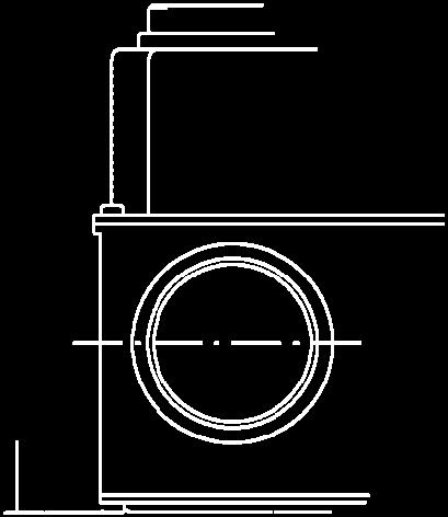
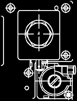
9 DIMENSIONAL DRAWING VRB15/VRB20/VRB Fig. 4. Dimensional drawing VRB15 (DN15), VRB20 (DN 20) and VRB25 (DN 25) 9 EN2R RD -NE
10 INSTALLATION IMPORTANT Read these instructions carefully. Failure to follow the instructions could damage the product or cause a hazardous condition. Check the ratings given in the instructions and on the product to make sure the product is suitable for your application. The installation has to be carried out by qualified personnel only. Carry out a thorough checkout when installation is completed. CAUTION Turn off gas supply before installation. Disconnect power supply to the valve actuator before beginning the installation to prevent electrical shock and damage to the equipment. Do not remove the seal over valve inlet and outlet, until ready to connect piping. The valve must be installed so that the arrow on the valve points in the direction of the gas flow (gas pressure helps to close the valve). WARNING Tightness test after installation Spray all pipe connections and gaskets with a good quality gas leak detection spray. Start the appliance and check for bubbles. If a leak is found in a pipe connection, remake the joint. A gasket leak can usually be stopped by tightening the mounting screws. Otherwise, replace the gas valve. Electrical connection CAUTION Switch off power supply before making electrical connections. All wiring must comply with local codes, ordinances and regulations. Use lead wire which can withstand 105 C ambient. Mounting position The combination valve can be mounted plus or minus 90 degrees from the vertical. Mounting location The distance between the gas valve and the wall/ground, must be at least 30 cm. Main gas connection 1. Take care that dirt does not enter the gas valve during handling 2. Remove the flanges from the valve. 3. Use a sound taper fitting with thread according to ISO 7-1 or new, properly reamed pipe free from swarf. 4. Apply a moderate amount of good quality thread compound to the pipe for fitting only, leaving the two end threads bare, PTFE tape may be used as an alternative. 5. Screw the flanges onto the pipes. 6. Ensure that the inlet and outlet flanges are in line and separate from each other enough to allow the valve to be mounted between the flanges without damaging the O -ring. 7. Place the O -ring. If necessary grease it slightly to keep it in place. 8. Mount the gas valve between the flanges using the bolts for each flange. 9. Complete the electrical connections as instructed in the electrical connection section. 10 EN2R RD -NE
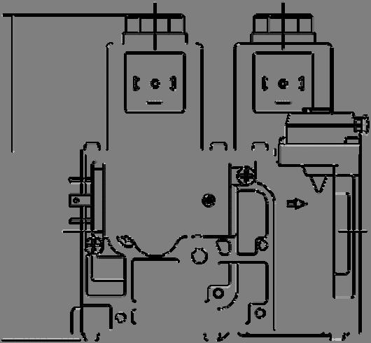
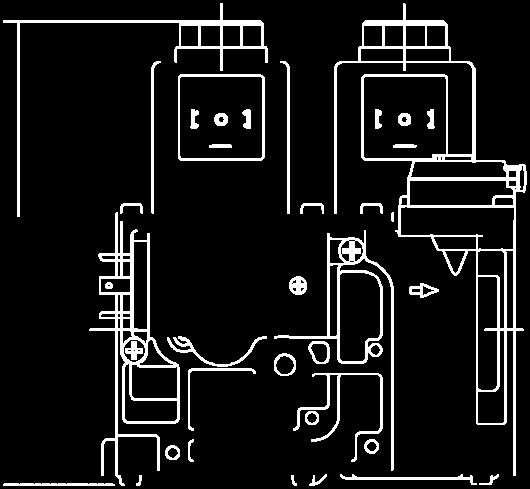
11 ADJUSTMENTS AND FINAL CHECKOUT Opening speed adjustment Opening speed is factory set at customer settings, the adjustment screw is sealed. The corresponding numbers can be found on the sides of the valve. Poutlet Flow regulation Step pressure Opening speed regulation time Fig. 5. Characterized opening. Adjustment outlet pressure Disconnect pressure feedback connection (if applicable) Energize both electric operators in order to have gas input to burner. Check gas input to the appliance using a clocking gas meter or alternatively a pressure gauge connected to the outlet pressure tap. Remove pressure regulator cap screw to expose pressure regulator adjustment screw. Slowly turn adjustment screw with a small screw driver until the burner pressure required is recorded on the pressure gauge. Turn adjustment screw clockwise to increase or counter -clockwise to decrease gas pressure to the burner. For non -regulating mode (LP gas) turn adjustment screw clockwise until it stops. Replace pressure regulator cap screw. Connect pressure feedback connection (if applicable). Pressure tap points The VRB00 Series has a number of connections points for measuring pressure, mounting a pressure switch, or IP applications. The following pressures can be measured: 1. Inlet pressure 2. Interim pressure (pressure between the two shut - off valves) 3. Outlet pressure Fig. 6. Pressure tap points Fig. 7. Pressure tap points Final checkout of the installation Set the appliance in operation after any adjustment and observe several complete cycles to ensure that all burner components function correctly. 11 EN2R RD -NE


12 CONSTRUCTION AND WORKING PRINCIPLES Servo pressure regulation working. The VRB00 Series servo regulated combination gas valves are 2 x class B fail safe shut -off valves. The valve is opened by energizing the direct ON/OFF operators. Each operator consists of a coil and a stop sleeve assy. Inside the stop sleeve assy is a plunger which is connected to a rubber valve and which is able to move up and down and thus opening or closing the valve. The plunger is coated with an anti friction material. A strainer made out of AISI303 is incorporated between inlet flange and main body. The valve closing springs are made of AISI302. Seals and gaskets are manufactured out of hydrocarbon resistant NBR according to DIN 3535 and EN 291 The VRB00 Series features the positive servo system, i.e. the regulating valve is closed by spring pressure in the normal shut down position and can only be opened when gas pressure is sufficient to overcome the spring force. This valuable built in safety feature ensures the regulating valve will automatically close in the event of power or gas supply failure. The heart of the system is the servo pressure regulator which consists of a pressure relief valve integrated in a regulator diaphragm which is fitted above and controls the regulating valve. When both operators are energized, inlet gas flows through the servo orifice into the servo system and into the regulator. This servo gas moves the regulating diaphragm upwards enough to open the regulating valve. As soon as the regulating valve has opened, the outlet pressure generated by the VRB00 Series will be sensed by the regulator diaphragm via the feedback channel. When the force operated by the pressure is greater than that preset by the adjustment screw, the regulator valve opens relieving some of the working pressure. This reduces the force against the regulating valve spring allowing the regulating valve to close proportionately. Thus the regulating valve limits the outlet (or burner) pressure to the preset level. As a result, outlet pressure is continuously maintained by comparing it to the preset pressure and adjusting the position of the regulating valve accordingly. This means that a constant outlet pressure is maintained regardless of inlet pressure variations. At shut down, the small volume of working gas in the regulator and in the diaphragm chamber is dumped into the main outlet chamber. A reference pressure feedback connection further regulates the outlet pressure by compensating for differences in the air pressure in the combustion chamber and at the valve. If pressure regulation working is not needed, the regulator spring can be blocked by turning the adjustment screw down until it stops or the pressure regulation is removed. In these cases the full servo gas pressure opens the regulating valve as far as the pressure drop allows. Fig. 8. Servo pressure regulator working 12 EN2R RD -NE
13 STANDARDS AND APPROVALS 13 EN2R RD -NE
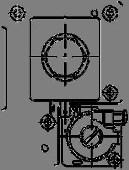
14 ORDERING INFORMATION How to select your valve Standard the VRB00 Series servo regulated combination valves are equipped with two main valves V1 and V2. Both valves are always fast opening/closing At the main body (8) flange connections are provided to mount either pressure switches, a pilot valve, or a VPS + pressure switch. These additional functionalities can be mounted on various positions of the main body of the VRB00. Ordering Specification number VR B xx A A 1xxx VR: dual gas valve Specification number Valve classification Characteristics 2 nd valve A: fast opening straight flange connection 15 DN15 (1/2 ) 20: DN20 (3/4 ) 25: DN25 (1 ) Type of pressure regulator A: Pressure regulator V: Gas/air 1:1 M: Modureg P: Hi -Lo NOTE: Flanges to be ordered separately (see Flange kits) Pressure switch (Min. C60VRB00 serie) is standard included (C6097 on request available)(position has to be specified, see table NO TAG on NO TAG. Fig. 9. Ordering information VRB00 Series combination valves 14 EN2R RD -NE
15 REPLACEMENT PARTS AND ACCESSORIES IMPORTANT When ordering replacement coils include the complete valve O.S. number, in order to provide the coil with proper product identification sticker. Model WARNING Take care that only qualified persons carry out the installation of parts, accessories, and add on components. Follow the installation instructions included in the package. Check that the selected part, accessory or add on component is the correct one for the application in question. Replace the old gaskets with the new ones supplied in the package and check for leakage when the supply is switched on again. After installation and/or replacement has been completed, a gas leak test must be carried out. Also check the gas valve for satisfactory operation after fitting accessories. Table 4. Coils for VRB00 series Order number Rated voltage (Vac) DN15 BB DN20/25 BB DN15 BB DN20/25 BB DN15 BB DN20/25 BB Table 5. Regulators Packing quantity Regulator type Range O.S.number Pressure regulator V5306E V5306E 1192 Two -stage V4336A 2020 Flange kits The kit consist of: - 1 flange with sealing plug - 1 O -ring and 4 screws Table 1. Flange kits Order number Size (Rp) Remarks KTCOMB15 1/2 with plug KTCOMB20 3/4 with plug KTCOMB25 1 with plug Electrical connectors DIN connector with integrated rectifier (2 connectors needed per VRB-series combination gas control): - CPCOMPM221 (pack quantity 10pcs) Replacement of coil WARNING Disconnect power supply before Beware of the spring under the coil 1. Remove capscrew on top of coil. 2. Remove coil. 3. Replace coil and tighten with capscrew: V1: plastic cap 2,5 Nm V2: steel nut 1,2 Nm; plastic cap 0,8 Nm Replacement of pressure regulator WARNING Disconnect power supply before 1. Disconnect pressure feedback connection (if present). 2. Loosen and remove screws from regulator. 3. Lift regulator. 4. Remove rubber gasket. 5. Place new gasket. 6. Place new regulator and fasten it with screws. 7. Reconnect pressure feedback connection. 8. Reconnect pressure and power supply. 9. Energize valve. 10. Check for leakage. Honeywell Europe: Honeywell Products & Solutions Sàrl Z.A. La LPièce Rolle Switzerland 15 EN2R RD -NE
VR400/VR800 SERIES. Honeywell CLASS A SERVO REGULATED COMBINATION VALVES APPLICATION. Contents PRODUCT HANDBOOK
 Honeywell VR400/VR800 SERIES CLASS A SERVO REGULATED COMBINATION VALVES APPLICATION PRODUCT HANDBOOK The VR400 Series class A servo regulated combination valves are used for control and regulation of gaseous
VR400/VR800 SERIES. Honeywell CLASS A SERVO REGULATED COMBINATION VALVES APPLICATION DESCRIPTION INSTRUCTION SHEET
 Honeywell VR400/VR800 SERIES CLASS A SERVO REGULATED COMBINATION VALVES APPLICATION INSTRUCTION SHEET The VR400 Series class A servo regulated combination valves are used for control and regulation of
VR400/VR800 SERIES UNIVERSAL GAS VALVES CLASS A SERVO REGULATED COMBINATION VALVES APPLICATION. Contents PRODUCT HANDBOOK
 UNIVERSAL GAS VALVES VR00/VR800 SERIES CLASS A SERVO REGULATED COMBINATION VALVES APPLICATION PRODUCT HANDBOOK The VR00 Series class A servo regulated combination valves are used for control and regulation
VR400/VR800 SERIES UNIVERSAL GAS VALVES CLASS A SERVO REGULATED COMBINATION VALVES APPLICATION. Contents PRODUCT HANDBOOK. General.
 UNIVERSAL GAS VALVES VR00/VR800 SERIES CLASS A SERVO REGULATED COMBINATION VALVES APPLICATION PRODUCT HANDBOOK The VR00 Series class A servo regulated combination valves are used for control and regulation
HUPF Series DESCRIPTION APPLICATION INSTRUCTION SHEET GAS PRESSURE REGULATOR WITH INCORPORATED FILTER EN1C-0003NL05 R1205.
 HUPF Series GAS PRESSURE REGULATOR WITH INCORPORATED FILTER INSTRUCTION SHEET DESCRIPTION Spring-loaded regulator with inlet pressure compensation and zero shut-off. The outlet pressure is kept constant
VR46.5V(A)/VR86.5V(A) SERIES
/VR86.5V(A) SERIES") VR46.5V(A)/VR86.5V(A) SERIES COMACT COMBINATION GAS CONTROS WITH INTEGRATED 1:1 GAS/AIR REGUATOR FOR AUTOMATIC IGNITION SYSTEMS SECIFICATIONS INSTRUCTION SHEET Subject to change without notice. rinted
VR46.5V(A)/VR86.5V(A) SERIES COMACT COMBINATION GAS CONTROS WITH INTEGRATED 1:1 GAS/AIR REGUATOR FOR AUTOMATIC IGNITION SYSTEMS SECIFICATIONS INSTRUCTION SHEET Subject to change without notice. rinted
VK41../VK81.. GAS CONTROLS FOR COMBINED VALVE AND IGNITION SYSTEM SPECIFICATIONS APPLICATION DESCRIPTION INSTRUCTION SHEET
 VK41../VK81.. GAS CONTROLS FOR COMBINED VALVE AND IGNITION SYSTEM SPECIFICATIONS INSTRUCTION SHEET Subject to change without notice. All rights reserved APPLICATION The Combined Valve and Ignition system
UL Listed GM-20/25 and GM-40/45 Series Dual-block Multi-function Gas Control Valves
 Installation Sheets Manual 121 Gas Combustion Combination Controls and Systems Section G Technical Bulletin GM-20/25 GM-40/45 Issue Date 1298 UL Listed GM-20/25 and GM-40/45 Series Dual-block Multi-function
VK8515M(R) MODULATING GAS CONTROL APPLICATION DESCRIPTION SPECIFICATIONS INSTRUCTION SHEET. Electrical data
 MODULATING GAS CONTROL APPLICATION DESCRIPTION SPECIFICATIONS INSTRUCTION SHEET. Electrical data") VK8M(R) MODULATING GAS CONTROL INSTRUCTION SHEET Main gas connection Connections with G / external thread fitted with nuts according to ISO 8- in combination with applicable sealing(s) withstand the torsion
VK8M(R) MODULATING GAS CONTROL INSTRUCTION SHEET Main gas connection Connections with G / external thread fitted with nuts according to ISO 8- in combination with applicable sealing(s) withstand the torsion
MULTIFUNCTIONAL CONTROL FOR GAS BURNING APPLIANCE
 SIT Group SIT -3- SIGMA MULTIFUNCTIONAL CONTROL FOR GAS BURNING APPLIANCE 9.955. Subject to change without notice Application Domestic gas appliances: central heating boilers, combi boilers, instantaneous
GM-7000 Series CE Approved Gas Control Valve
 Installation Instructions GM-7000 Issue Date November 9, 2012 GM-7000 Series CE Approved Gas Control Valve Installation IMPORTANT: These instructions are intended as a guide for qualified personnel installing
Dual Solenoid Gas Valve Installation
 Installation IMPORTANT: These instructions are intended as a guide for qualified personnel installing or servicing FLYNN Gas Products. Carefully follow all instructions in this bulletin and all instructions
GS-20/25 and GS-40/45 Series Single-block Multi-function Gas Control Valves
 Installation Sheets Manual 121 Gas Combustion Combination Controls and Systems Section G Technical Bulletin GS-20/25 GS-40/45 Issue Date 1298 GS-20/25 and GS-40/45 Series Single-block Multi-function Gas
GM Series Dual-Block Multi-Function Gas Control Valves
 Installation Sheets Manual 121 Gas Combustion Combination Controls and Systems Section G Technical Bulletin GM Issue Date 0297 GM Series Dual-Block Multi-Function Gas Control Valves Figure 1: GM Series
TANDEM MODULATOR FOR OUTLET GAS FLOW: STEPPED (836 TANDEM) - CONTINUOUS (837 TANDEM) SERVO-CONTROLLED PRESSURE REGULATOR
 - CONTINUOUS (837 TANDEM) SERVO-CONTROLLED PRESSURE REGULATOR") SIT Group 836-837 TANDEM MULTIFUNCTIONAL GAS CONTROL MODULATOR FOR OUTLET GAS FLOW: STEPPED (836 TANDEM) - CONTINUOUS (837 TANDEM) SERVO-CONTROLLED PRESSURE REGULATOR ALL ADJUSTMENTS ACCESSIBLE FROM ABOVE
SIT Group 836-837 TANDEM MULTIFUNCTIONAL GAS CONTROL MODULATOR FOR OUTLET GAS FLOW: STEPPED (836 TANDEM) - CONTINUOUS (837 TANDEM) SERVO-CONTROLLED PRESSURE REGULATOR ALL ADJUSTMENTS ACCESSIBLE FROM ABOVE
VK42.. / VK82.. SERIES
 VK42.. / VK82.. SERIES PX42 GAS CONTROLS FOR PREMIX COMBUSTION SYSTEMS PRODUCT HANDBOOK APPLICATION Energy preservation and reduction of CO 2 emissions are the main drivers for appliances with low emission
V46../V86.. series COMPACT COMBINATION GAS CONTROLS APPLICATION. Contents page Description... 2 Features... 3 PRODUCT HANDBOOK.
 V../V8.. series COMPACT COMBINATION GAS CONTROLS APPLICATION PRODUCT HANDBOOK The V.. and V8.. compact gas controls are servo-- operating combination gas controls and comprise a pilotstat, an operator
Operator: Save these instructions for future use!
 INLET PRESS TAP WHITE-RODGERS 36E93-304 Delay-Opening Combination Gas Valve INSTALLATION INSTRUCTIONS Operator: Save these instructions for future use! FAILURE TO READ AND FOLLOW ALL INSTRUCTIONS CAREFULLY
SPECIFICATIONS ATTENTION
 VPS 504 S06 Installation Manual - P/N 80122 - Ed. 01/09 VPS 504 S06 and S05 Valve Proving System Installation Instructions VPS 1 6 Gases Natural gas, air and other inert gases. NOT suitable for butane
GasBloc Multifunctional gas control Combined regulator and safety shut-off valves Electrically modulating GB-M(P) 055 D01
 055 D01") Gasloc Multifunctional gas control Combined regulator and safety shut-off valves Electrically modulating G-M(P) 055 D01 Two stage operating mode G-(LEP)Z 055 D01 3.0 Printed in Germany Edition 05.11 Nr.
Gasloc Multifunctional gas control Combined regulator and safety shut-off valves Electrically modulating G-M(P) 055 D01 Two stage operating mode G-(LEP)Z 055 D01 3.0 Printed in Germany Edition 05.11 Nr.
Old documentation - Only for your information! Product is not available any more!
 Gasloc Multifunctional gas control Combined regulator and safety shut-off valves Electrically modulating G-M(P) 055 D01 Two stage operating mode G-(LEP)Z 055 D01 3.0 Printed in Germany Edition 05.11 Nr.
36E DSI, HSI & Proven Pilot Two-Stage Combination Gas Valve INSTALLATION INSTRUCTIONS
 INLET PRESS TAP WTE-RODGERS 36E96-314 DSI, HSI & Proven Pilot Two-Stage Combination Gas Valve INSTALLATION INSTRUCTIONS Operator: Save these instructions for future use! FAILURE TO READ AND FOLLOW ALL
V5197A. Firing Rate Gas Valve APPLICATION FEATURES PRODUCT HANDBOOK
 V5197A Firing Rate Gas Valve PRODUCT HANDBOOK APPLICATION The V5197A are firing rate valves used to provide variable flow control of air, natural gas, liquefied petroleum (LP), and manufactured gases.
BGC258 Series BASOTROL Gas Valve
 Installation Instructions BGC258 Issue Date September 6, 2017 BGC258 Series BASOTROL Gas Valve Installation IMPORTANT: These instructions are intended as a guide for qualified personnel installing or servicing
36C/36D HSI, DSI Proven Pilot Gas Valves INSTALLATION INSTRUCTIONS
 36C/36D HSI, DSI Proven Pilot Gas Valves INSTALLATION INSTRUCTIONS Operator: Save these instructions for future use! FAILURE TO READ AND FOLLOW ALL INSTRUCTIONS CAREFULLY BEFORE INSTALLING OR OPERATING
36E DSI and HSI Two-Stage Combination Gas Valve INSTALLATION INSTRUCTIONS
 INLET PRESS TAP WTE-RODGERS 36E54-214 DSI and HSI Two-Stage Combination Gas Valve INSTALLATION INSTRUCTIONS Operator: Save these instructions for future use! FAILURE TO READ AND FOLLOW ALL INSTRUCTIONS
VK41../VK81..SERIES GAS CONTROLS FOR COMBINED VALVE AND IGNITION SYSTEM APPLICATION. Contents PRODUCT HANDBOOK
 VK41../VK81..SERIES GAS CONTROLS FOR COMBINED VALVE AND IGNITION SYSTEM APPLICATION PRODUCT HANDBOOK The Combined Valve and Ignition (CVI) system has been developed for application in gas fired domestic
36H SERIES Combination Gas Valve
 FAILURE TO READ AND FOLLOW ALL INSTRUCTIONS CAREFULLY BEFORE INSTALLING OR OPERATING THIS CONTROL COULD CAUSE PERSONAL INJURY AND/OR PROPERTY DAMAGE. DESCRIPTION The 36H series combination gas valve is
BGA158 Series CE Approved Class B Shutoff Gas Valve
 Installation Instructions BGA158 Issue Date March 22, 2016 BGA158 Series CE Approved Class B Shutoff Gas Valve Applications The BGA158 Series shutoff gas valve is an electrically operated shutoff valve
GasMultiBloc Combined regulator and safety valve Infinitely variable air/ gas ratio control mode MBC-300-VEF MBC-700-VEF MBC-1200-VEF
 GasMultiBloc Combined regulator and safety valve Infinitely variable air/ gas ratio control mode MBC-00-VEF 7.03 Max. operating pressure 30 mbar Compact design High flow values Low weight Low power consumption
BGA158 Series CE Approved Class A Shutoff Gas Valve
 Installation Instructions BGA158 Issue Date August 24, 2011 BGA158 Series CE Approved Class A Shutoff Gas Valve Applications The BGA158 Series shutoff gas valve is an electrically operated gas valve that
G196 Series BASOTROL Redundant Combination Gas Valve with Manual Shutoff Valve
 Installation Instructions Issue Date March 13, 2013 G196 Series BASOTROL Redundant Combination Gas Valve with Manual Shutoff Valve Application The G196 valves are suitable for use with natural gas, Liquefied
GasBloc Multifunctional gas control Combined regulator and safety shut-off valves single-stage atmospheric operating mode GB-(LEP) 057 D01
 057 D01") Gasloc Multifunctional gas control Combined regulator and safety shut-off valves single-stage atmospheric operating mode G-(LEP) 057 D01 3.10 Printed in Germany Edition 05.11 Nr. 249 584 1 6 Technical
Gasloc Multifunctional gas control Combined regulator and safety shut-off valves single-stage atmospheric operating mode G-(LEP) 057 D01 3.10 Printed in Germany Edition 05.11 Nr. 249 584 1 6 Technical
Old documentation - Only for your information! Product is not available any more!
 Gasloc Multifunctional gas control Combined regulator and safety shut-off valves single-stage atmospheric operating mode G-(LEP) 057 D01 3.10 Technical description Multifunctional gas control valve as
G196 Series BASOTROL Redundant Combination Gas Valve with Manual Shutoff Valve
 Installation Instructions Issue Date August 19, 2008 G196 Series BASOTROL Redundant Combination Gas Valve with Manual Shutoff Valve Application The G196 valves are suitable for use with natural gas, Liquefied
BGA158, BGA171 and BGA110 Series Shutoff Gas Valve
 Installation Instructions BGA Series Issue Date October 3, 2017 BGA158, BGA171 and BGA110 Series Shutoff Gas Valve Applications The BGA Series shutoff gas valve is an electrically operated gas valve that
36G22, 36G23, 36G24 & 36G52 36J22, 36J23, 36J24 & 36J52 DSI and HSI Single Stage Combination Gas Valve
 Operator: Save these instructions for future use! FAILURE TO READ AND FOLLOW ALL INSTRUCTIONS CAREFULLY BEFORE INSTALLING OR OPERATING THIS CONTROL COULD CAUSE PERSONAL INJURY AND/OR PROPERTY DAMAGE. DESCRIPTION
G96 Series BASOTROL Dual Operator Valve
 Installation Instructions 9. Issue Date February 22, 2013 G96 Series BASOTROL Dual Operator Valve Applications The G96 valves are combination, dual operator, automatic valves available with or without
SPECIFICATIONS CAPACITY
 DMV-ZRD(LE)/6 SERIES Installation Instructions SPECIFICATIONS DMV-ZRD/6 DMV-ZRDLE/6 Two normally closed safety shutoff valves in one housing. V1 and V2 are fast opening, fast closing. Two stage and adjustable
VK41../VK81..SERIES GAS CONTROLS FOR COMBINED VALVE AND IGNITION SYSTEM APPLICATION. Contents PRODUCT HANDBOOK
 VK41../VK81..SERIES GAS CONTROLS FOR COMBINED VALVE AND IGNITION SYSTEM APPLICATION PRODUCT HANDBOOK The Combined Valve and Ignition (CVI) system has been developed for application in gas fired domestic
GM-7000 Series CE Approved Gas Control Valve
 Product Bulletin Issue Date November 16, 2012 GM-7000 Series CE Approved Gas Control Valve The GM-7000 Series multi-function gas control valve works in conjunction with an electronic sequence control unit
36E03 and 36E38 DSI and HSI Step Opening Combination Gas Valve INSTALLATION INSTRUCTIONS
 INLET PRESS TAP WHITE-RODGERS 36E03 and 36E38 DSI and HSI Step Opening Combination Gas Valve INSTALLATION INSTRUCTIONS Operator: Save these instructions for future use! FAILURE TO READ AND FOLLOW ALL INSTRUCTIONS
SPECIFICATIONS. Normally closed automatic shutoff valve with proof of closure. Fast opening, fast closing. ATTENTION
 SV/614 Installation Manual -P/N 80128 - Ed. 01/08 SV-(DLE) 10../614 Safety Shutoff Valve with Proof of Closure Installation Instructions 1 6 SV/614 SV-DLE/614 SPECIFICATIONS Normally closed automatic shutoff
Solenoid gas valve. The solenoid gas valve is also applicable as a main gas valve Pilot gas valve for forced draft burners
 7 634 VGS1... with AGA67 connector VGS2... with AGA67 connector Solenoid gas valve VGS The solenoid gas valve is also applicable as a main gas valve Pilot gas valve for forced draft burners The VGS and
Operator: Save these instructions for future use!
 WHITE-RODGERS 6C8-5 Combination Gas Control INSTALLATI INSTRUCTIS Operator: Save these instructions for future use FAILURE TO READ AND FOLLOW ALL INSTRUCTIS CAREFULLY BEFORE INSTALLING OR OPERATING THIS
GasBloc Multifunctional gas control Combined regulator and safety shut-off valves Integrated gas-air system GB-GD 057 D01
 Gasloc Multifunctional gas control Combined regulator and safety shut-off valves Integrated gas-air system G-GD 057 D01 Zero pressure regulator G-ND 057 D01 3.12 Technical description Multifunctional gas
VR8305 Direct Ignition Combination Gas Control
 Honeywell VR8305 Direct Ignition Combination Gas Control Application These direct ignition combination gas controls are used in gas-fired appliances with capacities up to 300 feet 3 /hour at inch wc pressure
VR8105, VR8205, and VR8305 Direct Ignition Combination Gas Controls
 VR805, VR805, and VR8305 Direct Ignition Combination Gas Controls APPLICATION These direct ignition gas controls are used in gas-fired appliances with up to 45 ft 3 /hr capacity at in. wc pressure drop
Valve Proving System VDK 200 A S06*
 Valve Proving System VDK 200 A S06* Valve proving system with the following approvals. UL Recognized File # MH17004 CSA Certified File # 1637485 CSA Requirement No. 4-01 (USA) Technical Information Letter
WhirlWind Multifunctional gas control Fully integrated gas-air system with control and safety function GB-WND 055 D01
 WhirlWind Multifunctional gas control Fully integrated gas-air system with control and safety function Printed in Germany Edition 01 1 6 Technical Description Integrated gas-air system with high power
SV - Safety Shutoff Valve with Proof of Closure 1/2" NPT - 2" NPT. SV/614 Series SV-DLE/614 Series
 SV - Safety Shutoff Valve with Proof of Closure 1/2" NPT - 2" NPT SV/614 Series SV-DLE/614 Series Normally closed automatic shutoff valve with proof of closure and the following approvals. CSA Certified
Old documentation - Only for your information! Product is not available anymore!
 Double solenoid valve Regulator and safety combination Infinitely variable floating operation DM-EF 07-7. Printed in Germany Rösler Druck Edition 0.0 Nr. 9 Flanges, pressure switches, line sockets, pulse
G92 Series BASOTROL Automatic Pilot Gas Valve
 Installation Instructions Issue Date September 17, 2008 G92 Series BASOTROL Automatic Pilot Gas Valve Installation IMPORTANT: Only qualified personnel should install or service BASO Gas Products. These
Valve Proving System VDK 200 A S02
 Valve Proving System VDK 200 A S02 Valve proving system with the following approvals. UL Recognized File # MH17004 CSA Certified File # 1637485 CSA Requirement No. 4-01 (USA) Technical Information Letter
WhirlWind Combined fully integrated gas/air control and safety system GB-WND 055 D01
 WhirlWind Combined fully integrated gas/air control and safety system.04 Printed in Germany Edition 05.11 Nr. 40 508 1 6 Technical Description Integrated gas-air system with high power density based on
Operator: Save these instructions for future use!
 WHITE-RODGERS Type 36C67 Combination (24 Volt Models) INSTALLATION INSTRUCTIONS Operator: Save these instructions for future use! FAILURE TO READ AND FOLLOW ALL INSTRUCTIONS CAREFULLY BEFORE INSTALLING
Gas Pressure Regulator HON 300
 Product information serving the gas industry worldwide Applications, characteristics, technical data Applications direct acting gas pressure regulator, for systems in accordance with DVGW working instruction
Installation Instructions
 LP and High Altitude LP Gas Conversion Kit For United States Installations Installation Instructions For Model Series *G6/PGF1 Furnaces, *L1/PGC1 Furnaces, and *R4/PPG1 Gas/Electric Appliances using Honeywell
V8200A,C,H,M and VR8200A,C,H,M Continuous Pilot Combination Gas Controls
 V800A,C,H,M and VR800A,C,H,M Continuous Pilot Combination Gas Controls APPLICATION These continuous pilot combination gas controls are used in gas-fired appliances up to 00 cfh capacity of natural gas.
Pressure regulator with solenoid valve VAD Air/gas ratio control with solenoid valve VAG Variable air/gas ratio control with solenoid valve VAV
 Pressure regulator with solenoid valve Air/gas ratio control with solenoid valve Variable air/gas ratio control with solenoid valve VAV Product brochure GB 3 Edition 05.12 AGA All-purpose servo regulator
Operator: Save these instructions for future use!
 WHITE-RODGERS Type 36C04, 36C14 Step-Opening Combination Gas Control (24 Volt, 120 Volt & 750 mv Models) INSTALLATI INSTRUCTIS Operator: Save these instructions for future use! FAILURE TO READ AND FOLLOW
Operator: Save these instructions for future use!
 WHITE-RODGERS 36C53 Combination Gas Valves (24 Volt Model) INSTALLATI INSTRUCTIS Electrical Rating: Voltage: 24 Volts, (30 Volts Max.), 60 Hz. Current Rating: 0.23 Amps Type of Gas Natural Gas Pressure
VR8205S,T Direct Ignition Combination Gas Controls
 VR805S,T Direct Ignition Combination Gas Controls INSTALLATION INSTRUCTIONS APPLICATION TheVR805S,T Direct Ignition Combination Gas Controls are used in gas-fired appliances with up to 70 ft 3 /hr capacity
Governor with solenoid valve VAD Air/gas ratio control with solenoid valve VAG
 Governor with solenoid valve Air/gas ratio control with solenoid valve VAG All-purpose servo-governor for gaseous media with integrated safety valve Suitable for a max. inlet pressure of 500 mbar Outlet
Natural Gas to L.P. Gas Conversion Kit
 Natural Gas to L.P. Gas Conversion Kit For Bosch 96% AFUE Gas Furnace, BGH96 Model Installation Instructions 3124627 2 Natural Gas to L.P. Gas Conversion Kit Installation Instructions Data subject to change
Inverse Prop. Pressure-Relief Cart., Size 2 4
 Inverse Prop. Pressure-Relief Cart., Size Q max = l/min (6 gpm), p max = bar (58 psi) Direct acting, electrically operated Description inverse proportional pressure-relief valves are direct acting screw-in
SPECIFICATIONS ATTENTION
 DMV/602 Installation Manual - 80119-01/10 DMV-D(LE) 7../602 Dual Safety Shutoff Valve Installation Instructions Body size Flange Size DMV-D(LE) 701/602 1/2-1 NPT DMV-D(LE) 702/602 1-2 NPT DMV-D(LE) 703/602
Inverse Proportional Pressure-Relief Cart., Size 2 4
 Inverse Proportional Pressure-Relief Cart., Size Q max = l/min, p max = 35 bar Direct acting, electrically operated Description Compact construction for cavity type AL 3/-6 UNF Operated by a proportional
Pressure Reducing Valve DMV 750 set range: bar
 Pressure Reducing Valve DMV 750 set range:.0-6.0 bar Advantage pressure setting possible at any time, also during operation hermetically sealed by valve diaphragm high level of operating safety and long
Installation Instructions WARNING: WARNING: WARNING: LP AND HIGH ALTITUDE LP GAS CONVERSION KIT FOR UNITED STATES INSTALLATIONS
 LP AND HIGH ALTITUDE LP GAS CONVERSION KIT FOR UNITED STATES INSTALLATIONS Installation Instructions For Model Series *G7/*GC2 Furnaces and Appliances Using Honeywell Gas Valves. BEFORE THE CONVERSION
VMR VMR-OTN VMR 6 bar
 VMR VMR-OTN VMR 6 bar Safety solenoid valves for gas Fast opening and fast closing type DN8 DN150 delta-elektrogas.com EE161-03/17 VMR VMR-OTN VMR 6 bar Safety solenoid valves for gas Fast opening and
Bermad Pressure Reducing. Model: 42T
 Bermad Pressure Reducing Pilot Operated Pressure Control Valve Model: 42T Installation Operation Maintenance Manual (IOM) REV. 27.7.17 Page 1 of 12 Safety First BERMAD believes that the safety of personnel
INSTRUCTIONS FOR CONVERTING CONDENSING GAS MOBILE HOME FURNACES MODEL SERIES: CMA3*, CMC1*, VMA3*, VMC1*
 INSTRUCTIONS FOR CONVERTING CONDENSING GAS MOBILE HOME FURNACES MODEL SERIES: CMA3*, CMC1*, VMA3*, VMC1* THIS KIT CONTAINS: AOPS7741 (NATURAL TO PROPANE CONVERSION PARTS FOR MODEL SIZE, 50) AOPS7742(NATURAL
Natural Gas to L.P. Gas Conversion Kit
 Natural Gas to L.P. Gas Conversion Kit For Bosch 80% AFUE Gas Furnace, BGS80 Model Installation Instructions 3124627 2 Natural Gas to L.P. Gas Conversion Kit Installation Instructions Data subject to change
Proportional Throttle Cartridges, Size 16
 Proportional Throttle Cartridges, Size 16 Q max = 5 l/min, p max = 5 bar, Q N max = 14 l/min at p 1 bar Two-Stage, with Seat-Valve Shut-Off 1 Description Normally closed Seat-valve shut-off from 1 Compact
VR8200A Continuous Pilot Combination Gas Controls
 SUPER TRADELINE VR800A Continuous Pilot Combination Gas Controls Application These continuous pilot combination gas controls are used in gas-fired appliances that have up to 00 cfh capacity of natural
Proportional Pressure-Relief Cartridge Valve, Size 2...4
 Proportional Pressure-Relief Cartridge Valve, Size... Q max = l/min (6 gpm), p max = bar (58 psi) Direct acting, electrically operated Description proportional pressure-relief valves are direct acting
RS(H)10,15 USER MANUAL. Read the complete manual before installing and using the regulator.
10,15 USER MANUAL. Read the complete manual before installing and using the regulator.") RS(H)10,15 USER MANUAL Read the complete manual before installing and using the regulator. WARNING INCORRECT OR IMPROPER USE OF THIS PRODUCT CAN CAUSE SERIOUS PERSONAL INJURY AND PROPERTY DAMAGE. Due to
RS(H)10,15 USER MANUAL Read the complete manual before installing and using the regulator. WARNING INCORRECT OR IMPROPER USE OF THIS PRODUCT CAN CAUSE SERIOUS PERSONAL INJURY AND PROPERTY DAMAGE. Due to
Mounting and operating instructions EB 2530 EN. Self-operated Pressure Regulator. Pressure Reducing Valve Type M 44-2
 Self-operated Pressure Regulator Pressure Reducing Valve Type M 44-2 Type M 44-2, connection G 1 4, K VS = 0.15 Type M 44-2, connection G 1, K VS = 6 Fig. 1 Type M 44-2 Pressure Reducing Valve Mounting
VGD40.../VGD41... Double gas valves. Building Technologies Division Infrastructure & Cities Sector
 7 61 VGD20... Double gas valves VGD40.../VGD41... VGD2... VGD4... Double gas valves of class A for integration into gas trains Safety shutoff valves conforming to EN 161 in connection with SKPx5... actuators
Proportional Pressure-Relief Cartridge Valve, Size 2...4
 Proportional Pressure-Relief Cartridge Valve, Size... Q max = l/min, p max = 3 bar Direct acting, electrically operated 1 Description proportional pressure-relief valves are direct acting screw-in cartridges
Dual Modular Safety Shutoff Valves DMV-D 525/11 DMV-DLE 525/11
 Dual Modular Safety Shutoff Valves DMV-D 525/11 DMV-DLE 525/11 Two normally closed safety shutoff valves in one housing; each with the following approvals. CSA Certified ANSI Z21.21 CSA 6.5 Marked C/I
C645A-E Pressure Switches
 C645A-E Switches FEATURES PRODUCT DATA C645A,B,D,E GENERAL C645A,B with Window C645C The C645 pressure switches are safety devices used in positive-pressure or differential-pressure systems to sense gas
VR8104, VR8204, and VR8304 Intermittent Pilot Combination Gas Controls
 VR8104, VR8204, and VR8304 Intermittent Pilot Combination Gas Controls APPLICATION These intermittent pilot gas controls are used in gas-fired appliances with up to 415 ft3/hr capacity at 1 in. wc pressure
VS8420 Millivolt Gas Valve
 VS8420 Millivolt Gas Valve INSTALLATION INSTRUCTIONS APPLICATION The VS8420 Millivolt Gas Valve is compact and has a 60,000 Btuh capacity (1 in. pressure drop for straightthrough configuration). The design
Operator: Save these instructions for future use!
 WHITE-RODGERS Operator: Save these instructions for future use! FAILURE TO READ AND FOLLOW ALL INSTRUCTIS CAREFULLY BEFORE INSTALLING OR OPERATING THIS CTROL COULD CAUSE PERSAL INJURY AND/OR PROPERTY DAMAGE.
Operator: Save these instructions for future use!
 Pilot Gas Outlet: Located at outlet end of the valve Type of Gas Suitable for all domestic heating gases Pressure Rating: 1/2 lb. per sq. in. Pressure Regulator Adjust Range (Typical, See Control Label):
Dual Safety Shutoff Valves with Proof of Closure and NEMA 4x Enclosure. DMV-D/624L Series DMV-DLE/624L Series
 Dual Safety Shutoff Valves with Proof of Closure and NEMA 4x Enclosure DMV-D/624L Series DMV-DLE/624L Series Two normally closed automatic shutoff valves in one housing. Valve 2 (V2) incorporates proof
O.K. Safety first CDN USA. Table of Contents. Approvals. Attention IFGC CSA UL ANSI NFPA
 S06 & S02 Valve Proving System Installation Instructions USA CDN Table of Contents Table of Contents... Page 1 Approvals... Page 1 Attention... Page 1 Specification... Page 2 Mounting.... Page 3 Wiring...
GasMultiBloc Combined regulating and safety valve Infinitely variable air/gas ratio control mode MB-VEF B01
 GasMultiBloc Combined regulating and safety valve Infinitely variable air/gas ratio control mode MB-VEF 407-42 B0 7.27 Flange, line sockets, pulse lines and screw unions are not contained in the scope
Inverse Proportional Pressure-Relief Cart., Size 2 4
 Inverse Proportional Pressure-Relief Cart., Size Q max = l/min, p max = 5 bar Direct acting, electrically operated 1 Description inverse proportional pressure-relief valves are direct acting screw-in cartridges
Dual Modular Safety Shutoff Valves with Two-stage operation. DMV-ZRD/602 Series DMV-ZRDLE/602 Series
 Dual Modular Safety Shutoff Valves with Two-stage operation DMV-ZRD/602 Series DMV-ZRDLE/602 Series Two normally closed automatic shutoff valves in one housing; each with the following approvals. UL Recognized
D05 Pressure Regulating Valves
 D05 Pressure Regulating Valves FEATURES PRODUCT DATA Noncorroding unitized cartridge contains all working parts and is easily replaceable. Includes built-in strainer and thermal bypass. Balanced seat construction
SPECIFICATIONS FRS. 2 1/2 DN (ISO) Flanged. FRS DN (ISO) Flanged
 Flanged. FRS DN (ISO) Flanged") FRS Installation Manual - P/N 80109 - Ed. 01/09 FRS 7../6 NPT Threaded and FRS 5... ISO Flanged Gas Appliance Pressure Regulator/Line Pressure Regulator (Class I) Installation Instructions Body sizes Size
FRS Installation Manual - P/N 80109 - Ed. 01/09 FRS 7../6 NPT Threaded and FRS 5... ISO Flanged Gas Appliance Pressure Regulator/Line Pressure Regulator (Class I) Installation Instructions Body sizes Size
Dual Modular Safety Shutoff Valves with Proof of Closure. DMV-D/622 Series DMV-DLE/622 Series
 Dual Modular Safety Shutoff Valves with Proof of Closure DMV-D/622 Series DMV-DLE/622 Series Two normally closed automatic shutoff valves in one housing. Valve 2 (V2) incorporates proof of closure. Each
Dual Modular Safety Shutoff Valves. DMV-D/602 Series DMV-DLE/602 Series
 Dual Modular Safety Shutoff Valves DMV-D/602 Series DMV-DLE/602 Series Two normally closed safety shutoff valves in one housing; each with the following approvals. UL Recognized UL 429 File # MH16727 CSA
The installation and maintenance of this product must be done under the supervision of an experienced. Safety first O.K. IFGC CSA UL ANSI NFPA
 SV-(DLE) 10../604 Safety Shutoff Valves Installation Instructions USA CDN Table of Contents Table of Contents...Page 1 Approvals...Page 1 Attention...Page 1 Specification...Page 2 Mounting....Page 3 Painting
VR8305 Direct Ignition Dual Automatic Valve Combination Gas Controls
 Direct Ignition Dual Automatic Valve Combination Gas Controls The VR8305 Direct Ignition Dual Automatic Valve Combination Gas Controls are for use with direct ignition systems in gas-fired appliances.
CSA: Certified File No Never perform work if gas pressure or power is applied, or in the presence of an open flame. Safety first O.K.
 DMV-D(LE) 525/11 Threaded & DMV 5.../11 Flanged Dual Modular Safety Shutoff Valves Installation Instructions USA CDN Table of Contents Table of Contents...Page 1 Approvals...Page 1 Attention...Page 1 Specification...Page
GasMultiBloc Combined regulator and safety shut-off valves Single-stage function MB-D(LE) B01
 B01") GasMultiBloc Combined regulator and safety shut-off valves MB-D(LE) 05 - B0 7. Edition 0.8 r. 76 5 Technical description The DUGS GasMultiBloc integrates filter, regulator, valves and pressure switches
GasMultiBloc Combined regulator and safety shut-off valves MB-D(LE) 05 - B0 7. Edition 0.8 r. 76 5 Technical description The DUGS GasMultiBloc integrates filter, regulator, valves and pressure switches