Electronic controller for Closed Circuit Rebreather USER S MANUAL. version 1.0
|
|
|
- Morris Poole
- 5 years ago
- Views:
Transcription


1 Electronic controller for Closed Circuit Rebreather USER S MANUAL version 1.0
2 Table of Contents 2 User s manual 1. INTRODUCTION How to Use this Manual Important - Please Read DEFINITIONS INHERENT RISKS ASSOCIATED WITH DIVING A REBREATHER Risks and Their Management Explaining Risk Remaining Current and Fit to Dive Summary OPERATION OVERVIEW Activating the ECCR controller Buttons System Information Deactivating the ECCR controller Summary SURFACE MODE Primary Surface Display Change Setpoint Configuration Setpoint Setup Diluent and Gas Table Setup (only available when deco is enabled) Decompression Settings Other Settings Scrubber Settings Sensors and Calibration Switch Unit Off Summary UNDERWATER MODE Activating Underwater Mode Primary Underwater Display (Decompression Mode Activated) Primary Underwater Display (Decompression Mode De-Activated) Basic Underwater Display Change or Review Setpoint Options Cell Check by DIL Flush Setpoint Setup And Gas Table (Decompression Mode Activated) Setpoint Setup And Gas Table (Decompression Mode De-Activated) Setpoint Setup - Extended Mode (Decompression Mode Activated) Gas Mix List Configuration - Extended Mode (Decompression Mode Activated) Setpoint Setup - Extended Mode (Decompression Mode De-Activated) Decompression Settings Settings Calculating Decompression Summary PPO2 MEASUREMENT Summary BAILOUT MODE Bailout Menu Summary BATTERY LIFE AND CHARGING Battery Life Charging Summary BEFORE DIVING THE ECCR CONTROLLER ELECTRONICS Summary CARE AND MAINTENANCE Summary SOFTWARE UPDATE APPENDIX Operating conditions Depth gauge Temperature measurement Memory PC interface Battery User interface Handset mechanical and material characteristics Head-vup display mechanical and material characteristics General Warnings, Cautions, and Notices Tecdiving Limitation of Liability... 46
 and its charger; head-up display;")


3 1. INTRODUCTION This manual covers the use of ECCR controller and its accessories. The set consists of: ECCR controller (primary handset) and its charger; head-up display; pin plugs for primary and secondary controllers and head-up display; 4 pins Head-up display 6 pins Secondary handset 10 pins Primary handset connection board (analog or digital). 1.1 How to Use this Manual There are three parts of this manual, covering surface and underwater modes as well as general care and maintenance of the ECCR controller, software version The current version of manual is always available for read and download at help.eccr.pl. The manual covers each of the modes and the basic operation of the ECCR controller. While this manual is a useful guide for learning more about your rebreather s controller, it does not replace formal training with certified scuba instructor. 1.2 Important - Please Read With the purchase and / or use of the ECCR controller, you hereby agree to the Tecdiving Limitation of Liability as provided un the appendix of this manual. 3
4 2. DEFINITIONS Throughout this manual, there will be a variety of terms that a prospective or new rebreather diver may not be familiar with. This section will define these terms as they relate to this manual, as well as define the warning, caution, and notice symbols located throughout this text. Terms: Bailout: Open circuit SCUBA used as redundancy while diving a rebreather. Bar: Unit of measure equal to approximately one atmosphere. Used to calculate pressure at depth as well as PO 2. Battery: Power source located in the primary handset used to power the ECCR controller electronics. Status is measured in both volts and percentage of full charge. Bottom Time: Total elapsed time spent underwater. Calibration: Process used to align the oxygen sensor s millivolt output with a known PO 2. CCR: Closed Circuit Rebreather. Cell Cartridge: Removable cell carrier that houses the oxygen sensors. Cell Warning: Alarm which notifies the diver an oxygen sensor malfunction or dangerous loop PO 2. Ceiling: The shallowest depth one can ascend to at the current tissues saturation level. Carbon Dioxide (CO 2 ): The byproduct of oxygen metabolism in the body. Decompression: Reduction of ambient pressure experienced during the ascent from a dive. This term is also used to describe the mandatory stops a diver will need to make as they ascend from a dive. Desaturation (desat): The amount of time required for a diver s tissues to off gas all excess inert gas at the surface. Head: CCR electronics component which houses the cell car tridge, oxygen injection solenoid as well as handset and HUD Connections. Head-Up Display (HUD): Display mounted to the rebreather mouthpiece which indicates the status of the breathing loop via flashing LEDs. Loop: Internal volume of the CCR comprised of the mouthpiece, breathing hoses, counterlungs, scrubber canister, and head. Millivolt (mv): Unit of measure equal to one thousandth of a volt. Millivolts are used to measure the amount of current generated by an oxygen sensor. No Stop Time: Available time a diver can spend at the current depth without incurring a mandatory decompression obligation. OC: Open Circuit SCUBA. Oxygen Sensors (cells): Electro-galvanic fuel cell which generates an electric current when exposed to oxygen, used for sensing the PO 2 in the breathing loop. Piezo switch: Pressure sensitive switch used to navigate the ECCR controller and make adjustments to the unit s settings. 4
5 PPO 2 /PO 2 : Par tial pressure of oxygen; the concentration of oxygen in a breathing gas. PO 2 is determined by the fraction of oxygen in the gas and the absolute pressure exer ted on the gas (PPO 2 = fraction of oxygen x absolute pressure). Primary Handset: Housing containing the main electronics, battery, screen and two piezo switches for user interface. Scrubber/Stack: Terms used interchangeably to describe the CCR s carbon dioxide scrubber canister, usually used when describing scrubber/ stack duration remaining. Setpoint: User defined target loop PO 2. Surface Interval (surf. int.): Elapsed time spent on the surface after completing a dive. TTS: Time to surface, describes the total time required for the diver to ascend to the surface from their current position in the water. This includes the ascent at a rate of 7 meters/23 feet per minute as well as all required decompression obligations. Gradient Factors (GF): Values used to allow a diver to add conservatism to the Buhlmann decompression algorithm. Solenoid: Valve which injects oxygen into the breathing loop when activated by the ECCR controller. Warning, Caution, and Notice Statements Throughout this manual, there are special warning, caution and notice statements that highlight key information that need special attention. These notices are highlighted in the following format: WARNING - describe potentially hazardous situations, if not avoided, could result in serious injury or death. Avoid these situations under any circumstances. CAUTION - indicates a hazardous situation which, if not avoided, could result in minor or moderate injury. NOTICE - used to notify the user of information regarding installation, operation, maintenance, performance, general tips that are important, or statements describing a procedure or situation that might cause damage to the device but is unrelated to physical injury. 5
6 3. INHERENT RISKS ASSOCIATED WITH DIVING A REBREATHER There are many inherent risks associated with scuba diving, and diving a rebreather increases some of these risks. It is important to recognise and understand these risks and how to manage them, always obtain proper training from a qualified instructor, and remain current with your skills and knowledge. 3.1 Risks and Their Management Scuba diving may carry serious inherent risks that can result in serious injury or death if not managed properly. These risks include, but are not limited to, decompression sickness, oxygen toxicity, hypoxia, hyperoxia, drowning, hypercapnia or other CO2 related maladies, barotrauma including arterial gas embolism, other hyperbaric injuries, equipment malfunction or failure and risks arising from improper and/or negligent operation of equipment. While these risks are always present while diving a rebreather, they can be managed and even reduced by receiving proper training, diving within the limits of your training and experience, using proper pre-dive checklists, following manufacturer guidelines, staying current with your knowledge and skills, remaining physically and mentally fit to dive, and seeking further training from a qualified professional when you are looking to extend the limits of your training and experience or whenever there is an extended period of inactivity in your rebreather diving activities. If you do not acknowledge, understand or accept these risks, you must not dive the unit with ECCR controller. 3.2 Explaining Risk It is just as important for your close relatives to understand and accept the risks and potential consequences associated with diving a rebreather. If they are not willing to accept the consequences of your diving activities, you should not dive the ECCR controller. 3.3 Remaining Current and Fit to Dive Remaining physically and mentally fit to dive is critical for your safety in the water. While annual physicals are an excellent way to have your fitness assessed by a medical professional, it is also essential to assess your physical and mental readiness prior to every dive. If it doesn t feel right, it is not right. No dive is worth your life, and you should feel comfortable terminating any dive at any time for any reason. After any extended period of rebreather diving inactivity, it is important to seek refresher training from a qualified professional, and take it slow for the first few dives while building your skills and comfort level back up gradually. 6
7 3.4 Summary While diving a rebreather is a fun and exciting activity, it does pose inherent risks that cannot be avoided entirely. It is your responsibility to understand and accept these risks and be willing to accept the responsibility of keeping current and fit to dive prior to diving the unit with ECCR controller. If you are not willing to accept these risks and responsibilities, you should not dive the unit with ECCR controller. 7

.")
8 4. OPERATION OVERVIEW This chapter will cover the basic functions and operation of the ECCR controller, including how to navigate the displays, change settings, and overall system display information. 4.1 Activating the ECCR controller The ECCR controller can be activated 3 ways: manually, via the wet switches, or via the pressure sensor. The wet switches and pressure sensor activate the electronics in the event the user enters the water with the handset turned off (see Ch. 5, Underwater Mode, Activating Underwater Mode for more info regarding wet switch and pressure sensor activation). To activate the electronics manually, simply press and hold both piezo switches simultaneously until the initial screen appears on the display. If the primary handset is connected to the head, you will likely hear the solenoid activating (apparent clicking sound). This is normal and the reason for it will be explained later in this manual. 4.2 Buttons TThe ECCR controller (primary handset) has two piezo switches or buttons located ergonomically on the top and bottom of the handset. This section will define the buttons and their functions as well explain the basic navigation of the displays and settings. For the purposes of this text, we will define the buttons as: Bottom button: Select. This button allows you to scroll through the available options on the display, the chosen option will be highlighted or boxed in red. Top button: Confirm. Confirms the highlighted option, which either changes the option to the next available setting or increases the numerical value by one (1). Both buttons simultaneously: Next Menu. Changes displayed menu to the next available menu. Top button (Confirm) Bottom button (Select) 4.3 System Information The full colour display of the ECCR controller primary handset allows the user to quickly identify information that may require immediate attention while underwater, and to assist with navigating the menus and changing settings. For the purpose of navigating menus and changing settings on the surface, the colours are primarily used to easily highlight selections and changes being made. 8
9 Underwater, the text colour is used to highlight critical information that may need attention: Green: Value is within pre-determined or acceptable range. Yellow: Value is approaching unacceptable levels, not yet dangerous but requires the diver s attention. Red: WARNING! Value is now outside of acceptable and safe operating range, the ECCR controller may not be capable of operation as desired. Potentially dangerous and requires immediate action to avoid serious injury or death. 4.4 Deactivating the ECCR controller The ECCR controller electronics can only be turned off while in surface mode. To deactivate the electronics, use the next menu function until you reach the switch unit off display. Scroll to yes and press and hold the select button until the handset powers down. 4.5 Summary The ECCR controller s ergonomic buttons and colour display make navigating the primary handset simple and efficient. You will find that after only a short period you will become proficient in navigating the menus and adjusting settings. 9
10 5. SURFACE MODE Surface mode refers to the displays available when the diver is on the surface, where most of the user-configurable settings are adjusted prior to a dive. 5.1 Primary Surface Display This is the first display that appears when the ECCR controller powers up and gives general information about the controller including: Setpoint: The current user selected setpoint. Battery: Battery status shown in percentage of full as well as a voltage reading. The battery colour coding is as follows: Green: Yellow: Red: Battery is greater than 60% charged. Battery is greater than 30% but less than 60% charged, this requires attention. Battery is less than 30% charged, this requires immediate action. Scrubber: Full illustrates the duration of a new scrubber. Left: Illustrates the duration remaining on the existing scrubber as shown: Green: Yellow: Red: Scrubber has greater than 50% duration remaining. Scrubber has less than 50% but more than 25% duration remaining, this requires attention. Scrubber has less than 25% duration remaining, this requires immediate action. Owner: Name of the ECCR controller owner, this can only be modified by the Tecdiving factory. Soft: indicates the current software version of the ECCR controller Date and Time Deco: The current decompression algorithm selected. Surf int: Time on the surface since the last dive (in hours). Desat: Indicates the divers current tissue saturation percentage. Dil: Displays the current diluent gas activated. Sensor 1, 2, 3: Displays the PO 2 reading as well as the millivolt (mv) output for each oxygen sensor. The oxygen sensor colour coding is as follows: 10

11 Green: Yellow: Red: PO 2 value is within 15% of the user selected setpoint. PO 2 value is greater than 15% but within 25% of the user selected setpoint, is less than 0.5 but greater than 0.4, or greater than 1.5 but less than 1.6, this requires attention. PO2 value is more that 25% away from the user selected setpoint, is less than.4, or more than 1.6, this requires immediate action. 5.2 Change Setpoint The change setpoint menu allows the user to quickly select a pre-defined setpoint. Also displayed on this screen is the current PO 2 (average), time, depth, and current setpoint. To change the setpoint, press the SELECT button until the desired setpoint is circled in red and then press the CONFIRM button. You will see the current setpoint value change to the selected setpoint, and the change was successful. It is important to note the ECCR controller will only allow you to select a setpoint that it is capable of achieving. For example, a PO 2 of greater than 1.9 is not achievable on the surface, so the ECCR controller will not allow you to select any setpoint greater than 1.0 from the available options. 5.3 Configuration The configuration menu allows the user to configure following options: HUD Mode: Allows the user to set the Head-Up Display in one of 3 configurations: > > Alarms - The HUD s blue LED will flash once every 3 seconds when all systems are functioning normally and no immediate attention or action from the diver is required. The HUD s red LED will flash once every second as an alarm indicating the scrubber duration remaining, battery charge level, or PO 2 value needs the diver s attention or immediate action. 11

12 > > PPO 2 - The HUD will flash in a coded sequence to inform the diver of the average PO 2 value: x1 One red flash followed by 3 sec pause PPO under 1 = 0.9 x2 Two red flashes followed by 3 sec pause PPO under 1 = 0.8 x3 Three red flashes followed by 3 sec pause PPO under 1 = 0.7 x4 Four red flashes followed by 3 sec pause PPO under 1 = 0.6 x5 Five red flashes followed by 3 sec pause PPO under 1 = 0.5 x6 Six red flashes followed by 3 sec pause PPO under 1 = 0.4 x7 Seven red flashes followed by 3 sec pause PPO under 1 = 0.3 x8 Eight red flashes followed by 3 sec pause PPO under 1 = 0.2 x9 Nine red flashes followed by 3 sec pause LOW PPO 2 constant warning x1 One blue flash followed by 3 sec pause PPO over 1 = 1.1 x2 Two blue flashes followed by 3 sec pause PPO over 1 = 1.2 x3 Three blue flashes followed by 3 sec pause PPO over 1 = 1.3 x4 Four blue flashes followed by 3 sec pause PPO over 1 = 1.4 x5 Five blue flashes followed by 3 sec pause PPO over 1 = 1.5 x6 Six blue flashes followed by 3 sec pause PPO over 1 = 1.6 Red and blue flash simultaneously followed by a 3 second pause PPO 2 = 1 12
13 > > Sequential - This mode is the same as PPO 2 mode, however instead of averaging the cell readings, the HUD will indicate each of the 3 sensors individually in a sequential pattern (one at a time starting with cell 1, going on to 2 and 3 then loop back to cell 1). For example: One blue flash: 3 second pause, 2 blue flashes, 3 second pause, 1 blue flash, 3 second pause would indicate: Sensor 1 = 1.1; Sensor 2 = 1.2; Sensor 3 = 1.1 Units: Allows the user to configure the ECCR controller to display in either imperial or metric units of measure. Brightness: User can select one of several display brightness settings: > > Auto - auto mode senses ambient light level and adjusts the brightness automatically (less ambient light, lower the brightness setting; more ambient light, higher the brightness setting). > > Low - the lowest brightness setting consumes the least amount of power. > > Medium - the medium brightness setting consumes an intermediate amount of power. > > High - the highest brightness setting consumes the most power. Flip Screen: if the user would like to wear the primary handset on the right wrist, they can turn flip screen on to turn the display upside down. Set Time: user can set current time for accurate dive logging. Set Date: user can set date for accurate dive logging. Big TTS: when turned on, the Time To Surface (TTS) will be displayed on the basic display in underwater mode. The TTS will alternate with dive time in the top right corner of the display. The TTS will display for 2 seconds and the dive time will display for 6 seconds. Salnity: choice between fresh or salt water. There are additional options available in the configuration menu such as: Log Book: The logbook displays dives logged on the ECCR controller primary handset. The main display includes information about dive numbers and dates of recent dives. To access details of a particular dive, it has to be highlighted (scroll button) and then chosen (select button). Once a dive is selected you can view the following information: Dive number Date and time of star ting the dive Dive time Maximum depth Setpoint information Surface interval Water temperature Air temperature 13
14 When viewing the dive, pressing the confirm button will take the user to the dive graphs where they can view the following (pressing the confirm button will scroll form one graph to the next): 1.00 PPO2 graph Average ppo2: Depth graph PPO 2 graph Temperature graph Consolidated graph (depth, PO 2 and temp.) Service Menu: The service menu is accessed and utilized only when conducting ECCR controller factory service and testing only. Unauthorized use of this option will lock the ECCR controller electronics. Unit Info: displays detailed ECCR controller information for the life to date of the unit including: > > Unit No. and Unlock PIN: this function opens the menu to enter feature unlock PIN and displays the Unit No (different than the serial number stamped on the back of the handset). > > Run Time: the total time the unit has been turned on. > > Time Underwater: the total time the unit has been in underwater mode. > > Max. Depth: maximum depth of all dives conducted. > > Scrubber Exchange: number of times the scrubber timer has been reset. > > Last Factory Service: date the last factory service was performed. > > Manufacturing Date: production date of the unit. 14
15 Hardware Configuration: the user can set the piezo switch press duration (button sensitivity) as well as configure the order in which the oxygen sensors are displayed. > > Piezo time: changes the duration in which you If you find you are accidentally changing settings unintentionally, you may want to increase the piezo time to make the button pushes less sensitive. It is important to note, changing this setting does not affect how much force is required to push the button, only how long you must hold it before it registers. > > Signal Config: allows the user to configure the order in which the oxygen sensors are displayed on the handset. This is valuable to ensure your primary and secondary handsets are reading sensors in the same order and the values are consistent. > > mbar Offset: allows the user to adjust the milli bar value based on the actual known atmospheric pressure to offset the slight deviance due to the pressure sensor accuracy. This will allow for a slightly more accurate calibration, but is not required for normal operation. > > Pressure value: displays measured pressure. > > Software upgrade: allows to upgrade the software version to a newer one if available. In standard surface mode, the setpoint setup menu enables the user to define their preferred low and high setpoints. The selectable range for both SP1 and SP2 is from 0.5 through 1.6. To define a setpoint value, press the SELECT button until the setpoint you would like to adjust is flashing and press the select button. This will highlight the setpoint in red, and further pushes of the CONFIRM button will increase the value by 0.1. When you have reached the desired value, press the SELECT button to move to the next setpoint. When you are finished, you can use the next menu function to scroll to the next menu. The diluent and gas table setup is where the user will define their diluent and open circuit gases. must hold the piezo switches down in order for the button to register a press. The lower the value selected, the shorter the duration and the more sensitive the buttons will be to pushes. 5.4 Setpoint Setup 5.5 Diluent and Gas Table Setup (only available when deco is enabled) In order to adjust the oxygen (O 2 ) and helium (He) values, the gas must be deactivated. 15
16 To deactivate and adjust a diluent gas, simply scroll to the --- in the Active column of another diluent gas and press CONFIRM. This will activate that diluent gas (indicated by act ), and you will now be able to adjust the values of the desired diluent gas. To adjust the O 2 and He percentages, scroll to the value you wish to adjust and press the CONFIRM button to increase the value by 1% per push. When a value is at the desired level, press the SELECT button to move to the next value or gas. To deactivate and adjust an open circuit bailout gas (OC gas x), simply scroll to act for the corresponding OC gas you would like to adjust, and press CONFIRM. This gas will now be deactivated (indicated by --- ), and you can adjust the O 2 and He values. 5.6 Decompression Settings The use of nitrox and/or trimix requires specialized training. Do not attempt to dive with any diluent gas other than standard air without specialized training and certification. Modifying decompression settings can have drastic and negative effects on a diver s decompression profile, resulting in serious injury or death. By modifying any values in the Decompression Settings menu, a diver acknowledges that they fully understand the implications of doing so. Model: user may select Zhl16+GF or No Deco. When No Deco is selected, tissue loading calculations are not displayed, and it is extremely important the diver uses another means (secondary handset and/or constant PO 2 CCR computer) to calculate decompression status. Gr. Factor Hi: allows the user to adjust the high gradient factor. Gr. Factor Lo: allows the user to adjust the low gradient factor. Last Deco Stop: allows the user to select between 2 predetermined values (3 meters/10 feet, or 6 meters/20 feet) for their final decompression stop. Dive Planner: user can enter the parameters of the dive and calculate the expected decompression obligation. 16
17 5.7 Other Settings Underwater: the user may select sensor or permanent. Sensor: uses the ECCR controller s depth pressure sensor and/or wet switch to activate underwater mode. Permanent: places the primary handset into underwater mode permanently, enabling the user to view the underwater mode displays and settings while on land. 5.8 Scrubber Settings This display allows the diver to configure the scrubber settings based on the scrubber canister option installed on their rebreather with ECCR controller as well as reset the scrubber countdown timer when the CO 2 absorbent is replaced. Stack Changed: indicates the duration since the CO 2 absorbent was last changed. The colour coding is as follows: Green: Yellow: Red: The ECCR controller will not power down while in underwater mode. If permanent is selected, the user must select sensor when they wish to shut the ECCR controller down. Failure to do so will result in the handset remaining on and discharging the battery. The ECCR controller has an automatic timer that will not allow the handset to enter surface mode until it has been on the surface for 60 seconds. This timer will also prevent the handset from entering surface mode for 60 seconds after sensor has been re-selected while on the surface. Scrubber was replaced within the past 50 days. It has been more than 50 days, but less than 150 days since the last scrubber replacement. It has been more than 150 days since the scrubber was replaced. Current Stack Time: indicates the duration remaining on the current scrubber canister. This duration is determined by subtracting the elapsed dive time since the last scrubber exchange from the set stack time value. Set Stack Time: allows the user to configure the scrubber duration based on the CO 2 canister installed on their rebreather with ECCR controller. See the rebreather s manual or contact the manufacturer for details regarding scrubber canister options and durations. A user should ONLY reset the stack time in accordance with the CO 2 absorbent canister option iinstalled on their rebreather with ECCR controller. This is a maximum scrubber duration based on optimal conditions, and additional precautions should be taken when other factors may reduce scrubber duration (increased workload, cold water, depths exceeding 40 meters/130 feet). Exceeding the scrubber duration may result in serious injury or death. 17
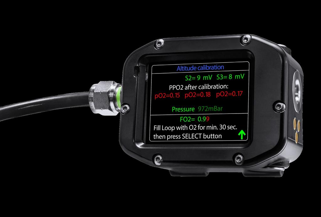
18 Reset Stack Time and Scrubber Exchange: allows the user to reset the scrubber countdown timer when the CO 2 absorbent material has been replaced. Sensor Age: indicates the elapsed time in days since the sensor was installed in the unit. The colour coding is as follows: prepared to replace it within the next 60 days. Last Calibration: indicates the elapsed time in days since the unit was last calibrated. Diluent PPO 2 : fraction of oxygen in the activated diluent. Altitude Calibration: allows the user to enter altitude calibration menu, to be used when calibrating the ECCR controller electronics at altitude or when calibrating using a calibration gas other than pure oxygen. > > S1, S2, S3: voltage (given in millivolt) of each oxygen sensor. > > PPO 2 after calibration: PO 2 reading of each cell after successful calibration. CAL will be displayed if a sensor has been calibrated incorrectly, indicating the unit will need to be recalibrated. Colour coding is consistent with deviation from setpoint PO 2 colouring used in other displays. A user should OLNY reset the stack timer when CO 2 absorbent material has been replaced with unused approved CO 2 absorbent using proper scrubber packing procedures. Please refer to your rebreather manufacturer s manual and your instructor for instructions on scrubber packing procedures for the rebreather. Failure to do so may result in serious injury or death. 5.9 Sensors and Calibration Green: Yellow: Red: Proper oxygen sensor care, calibration, and replacement is essential for proper CCR Function. Users should only install rebreather s manufacturer approved oxygen sensors in their ECCR electroncis. Oxygen sensors should be replaced after 18 months of manufacture, 12 months of installation, when mv output begins to degrade, the cell becomes non-linear or current limited, or the sensor fails to calibrate successfully, whichever comes first. Failure to do so may result in serious injury or death. Sensor was replaced within the past 150 days. Sensor was replaced between 150 and 300 days ago. Sensor was replaced more than 300 days ago, and the user should be > > Pressure: current atmospheric pressure. > > FO 2 : Current fraction of oxygen in the calibration gas as defined by the user. FO 2 can be adjusted from 0.96 to 0.99 by scrolling to the value to be edited and pressing the select button to select the value to match the calibration gas being used. 18
19 > > Fill Loop with O 2 for a minimum of 30 seconds then press the SELECT Button. After flushing the loop or head (if calibration caps are used) with oxygen, scroll to the up arrow icon and press the select button to calibrate the ECCR controller electronics to the oxygen sensor s mv reading output. A sensor that has calibrated successfully will be GREEN and have OK listed below it. A failed sensor will be RED and FAIL will be displayed below it. In order for the sensor to be calibrated correctly, its voltage value must be in the range of 37mV 62mV. In case of a failed calibration, the process has to be repeated until each sensor s reading is OK, or the sensor may need to be replaced. A dive should never be started with a known oxygen sensor failure or failed calibration. Successful calibration does not ensure a properly functioning oxygen sensor. It is advised to check periodically the sensors for linearity and current limiting, as well as track each sensors mv output. Failure to do so may result in serious injury or death. Standard Calibration: Allows the user to enter the standard calibration menu to calibrate the ECCR controller electronics using 100% oxygen at or near sea level. > > S1, S2, S3: voltage (given in millivolts) of each oxygen sensor. > > Fill Loop with oxygen for a minimum of 30 seconds then press the SELECT button. After flushing the loop or head (if calibration caps are used) with oxygen, scroll to the up arrow icon and press the SELECT button to calibrate the ECCR controller electronics to the oxygen sensor s mv reading output. A sensor that has calibrated successfully will be GREEN and have OK listed below it. A failed sensor will be RED and FAIL will be displayed below it. While the ECCR controller electronics incorporate sensor failure modes which estimate loop PO 2 and continue to function when one or more sensors fail, it is never appropriate to begin a dive with a known malfunctioning oxygen sensor. Attempting to do so can lead to serious injury or death. In the case of a single oxygen sensor failing to calibrate, the cell voting protocol is switched off, and average of the other two sensors is taken. In case of the failure of two sensors, the reading of the third sensor is taken as average PPO 2 and SOLENOID IS PERMANENTLY SWITCHED OFF. In case of all three sensors failure, no information about PPO 2 is given and SOLENOID IS PERMANENTLY SWITCHED OFF. 19
20 5.10 Switch Unit Off Dive time: Duration of the last recorded dive. Max depth: Maximum depth of the last dive. High setpoint: Maximum setpoint value set during the last dive. Surf int: Surface interval since the last dive. CNS: Current value of CNS oxygen exposure. OTU: Current value of oxygen tolerance units Summary Surface mode offers a wide variety of user definable options that the user should spend a considerable amount of time familiarizing themselves with and configuring the ECCR controller electronics to suit their preferences. 20

21 6. UNDERWATER MODE The ECCR controller electronics underwater mode allows the user quick access to critical dive related information, while allowing the user to change settings and configurations as the dive parameters change. Most of the underwater displays and configurations are very similar to the surface mode displays, with one primary difference; every display in underwater mode includes the average PO 2, dive time and current depth. 6.1 Activating Underwater Mode Underwater mode can be activated in one of three ways: Wet contacts: the board detects the increase of electric conductivity caused by water appearing between the contact (marked red) and ground contact (marked blue). Completing the circuit of these contacts causes the device to power on (if currently off) and switch into underwater mode. Depth sensor: the depth sensor is placed on the side of the controller housing and is protected from mechanical damages by a metal shield (marked red). The pressure sensor is calibrated by the factory to read a measuring range of 0 to 30 Bar. 6.2 Primary Underwater Display (Decompression Mode Activated) With decompression mode activated, the primary underwater display will give the user a complete overview of the dive and rebreather status. Information included in this display include: Ceiling: the shallowest depth given one can ascend to at the current tissues saturation. Time: elapsed time of the current dive. Depth: current depth. Setpoint: current user selected setpoint. Battery: status of battery (displayed in % of full charge). Scrubber: remaining scrubber duration. Sensor 1, Sensor 2, Sensor 3: current PO 2 value for each oxygen sensor. Last Stop: user selected last stop depth. Stop: time and depth of the first required decompression stop when the diver begins to ascend. 21
22 Gas: current gas (diluent or OC bailout) selected by the user. CNS: current CNS% TTS: total time to surface, the amount of time in minutes that it will take for the diver to reach the surface, includes ascent at 7 meters/23 feet per minute, and all required decompression stops. 6.3 Primary Underwater Display (Decompression Mode De-Activated) With decompression mode deactivated, most of the same information will be displayed on the primary underwater display, minus decompression related data. PPO 2 : Because the diver s decompression obligation is not being displayed, ceiling is replaced with PPO 2. This displays the average PPO 2 of the oxygen sensors or the PO 2 of the OC bailout gas if in OC bailout mode. 6.4 Basic Underwater Display The basic underwater display is designed to be a quick reference of the most critical dive information, displayed in large, easy to read font. This display is found by pressing the confirm button once while in the primary underwater display. Here you will find the following information: Time: elapsed dive time underwater of the current dive, displayed in the top left corner of the display. When big TTS is activated in the configuration mode, this display will alternate between TTS and Time (Time is displayed for 6 seconds, TTS is displayed for 2 seconds). TTS: time To Surface, only displayed when big TTS is turned on in the configuration mode, this display will alternate between TTS and Time (Time is displayed for 6 seconds, TTS is displayed for 2 seconds). Depth: current depth PPO 2 : average PO 2 currently in the breathing loop. NDL min: NDL remaining on the current dive. When the user enters decompression, NDL will be replace by Stop, which indicates the time and depth of the first required decompression stop. 22
23 6.5 Change or Review Setpoint Options The change setpoint menu allows the user to quickly select a pre-defined setpoint or manual (M) mode. Also displayed on this screen are the current PO 2 (average), time, depth, and current setpoint. To change the setpoint, press the SELECT button until the desired setpoint is circled in red and then press the CONFIRM button. You will see the current setpoint value change to the selected setpoint, and the change was successful. 6.6 Cell Check by DIL Flush This display allows the user to quickly identify what the expected PO 2 of the diluent gas should be for oxygen sensor verification purposes. On this display, you will see: Depth: current depth Time: current elapsed dive time. Diluent: current diluent gas mix Expected DIL PPO 2 : expected PO 2 of the diluent gas at the current depth. ECCR controller will only allow the user to select a setpoint that it is capable of achieving. For example, a PO 2 of greater than 1.0 is not achievable on the surface, so the ECCR controller will not allow you to select any setpoint greater than 1.0 from the available options. Sensor 1/2/3: current reading of oxygen sensors. The readings may be shown in one of the three colours due to deviation from expected DIL PPO 2 value: Green: Yellow: Red: PO 2 value is within 15% of the expected value. PO 2 value deviation is greater than 15%, but within 25% PO 2 value deviation is more that 25% A diluent flush resulting in a positive validation of an oxygen sensor does not guarantee that sensor s health. Your rebreather instructor will train you in proper sensor validation techniques. If an oxygen sensor s health comes into question at any point in a dive, the dive should be aborted immediately. Do not attempt to continue a dive with a questionable oxygen sensor. 23
24 6.7 Setpoint Setup And Gas Table (Decompression Mode Activated) The setpoint setup menu while in underwater mode is identical to surface mode, with the addition of the current average PPO 2, dive time, and depth listed at the top. This allows the user to monitor critical dive data while configuring setpoint underwater. The setpoint setup menu enables the user to define their preferred low and high setpoints and gas set up. By pressing SELECT button you move through SP1, SP2 and values of oxygen and helium in gas setup table. The selectable range for both SP1 and SP2 is from 0.5 through 1.6. To define a setpoint value, press the SELECT button until the setpoint you would like to adjust is flashing and press the CONFIRM button. This will highlight the setpoint in red, and further pushes of the CONFIRM button will increase the value by 0.1. When you have reached the desired value, press the SELECT button to move to the next value. The diluent and gas table setup is where the user will define their diluent and open circuit bailout gases. The Diluent gas is marked as active (in blue colour) and is impossible to deactivate. However, its values can be changed, simply select the desired digit in the O2 or He column and press confirm. This will change the value of 1. To move to the next digit / value, press Select button. To deactivate and adjust values of one of the three open circuit bailout gases (OC gas x), simply scroll to the act in the Active column of that gas and press confirm. This gas will now be deactivated (indicated by ) and you will now be able to adjust the values of the desired gas. To adjust the O2 and He percentages, scroll to the value you wish to adjust and press the CONFIRM button to increase the value by 1 per push. When a value is at the desired level, press the SELECT button to move to the next value or gas. The sum of Oxygen and Helium values in one gas mix cannot be greater than 100. When you are finished, you can use the next menu function to scroll to the next menu. 24
25 6.8 Setpoint Setup And Gas Table (Decompression Mode De-Activated) The setpoint setup menu while in underwater mode is identical to surface mode, with the addition of the current average PPO 2, dive time, and depth listed at the top. This allows the user to monitor critical dive data while configuring setpoint underwater. The setpoint setup menu enables the user to define their preferred low and high setpoints and gas set up. By pressing SELECT button you move through SP1, SP2 and values of oxygen and helium in gas setup table. The selectable range for both SP1 and SP2 is from 0.5 through 1.6. To define a setpoint value, press the SELECT button until the setpoint you would like to adjust is flashing and press the CONFIRM button. This will highlight the setpoint in red, and further pushes of the CONFIRM button will increase the value by 0.1. When you have reached the desired value, press the SELECT button to move to the next setpoint. 6.9 Setpoint Setup - Extended Mode (Decompression Mode Activated) The setpoint setup menu while in underwater mode is identical to surface mode, with the addition of the current average PPO2, dive time, and depth listed at the top. This allows the user to monitor critical dive data while configuring setpoint underwater. 25
26 6.10 Gas Mix List Configuration - Extended Mode (Decompression Mode Activated) The gas mix setup menu in underwater mode is identical to surface mode, with the addition of the current average PPO 2, dive time, and depth listed at the top. This allows the user to monitor critical dive data while configuring gasses while underwater Setpoint Setup - Extended Mode (Decompression Mode De-Activated) See Setpoint Setup information listed above in section Decompression Settings The decompression settings menu in underwater mode allows the user to make adjustments to the decompression related configurations during the dive. The user can adjust: Model: enables and disables the decompression mode. GR. Factor HI: adjusts the high gradient factor value. GR. Factor Lo: adjusts the low gradient factor value. Last Deco Stop: depth the last decompression stop is to be conducted. Dive Planner: this function is disabled in underwater mode. Other information listed on this screen is the basic dive information across the top, which includes average PPO 2, elapsed dive time, and current depth; as well as the current gradient factor which is determining the stop depth and time and the current water temperature. 26
27 6.13 Settings The settings menu allows the user quick access to general handset configurations such as: HUD Mode: allows the user to choose between Alarms, PPO 2, and Sequential mode. Units: user can define their preferred unit selection, Imperial or Metric. Brightness: allows the user to adjust the brightness settings. Flip Screen: allows the user to inver t the screen. Underwater: allows the user to choose between Permanent and Sensor for dive detection. Piezo Time: user can adjust the sensitivity of the piezo switches. Salinity: choice between fresh and sea water 6.14 Calculating Decompression The ECCR controller s electronics utilize Bühlmann s ZHL16+GF decompression algorithm, providing reliable and user configurable decompression information. After activating the controller, the decompression data is loaded from the non-volatile memory. In the vent of damage or complete battery discharge resulting in a loss of decompression information, the following warning will be displayed. Once decompression information is lost, the ECCR controller can no longer be relied on for accurate ecompression information for repetitive dives, as it will not account for residual tissue loading. For the decompression calculation to be valid, the appropriate diluent or open circuit bailout gas must be selected on the ECCR controller. When a dive commences the decompression model is initiated and the procedure of calculating the tissues saturation starts. The feature works continuously in real-time which makes it possible to switch the displayed decompression data on/off at any point, without the risk of losing the calculations or the correctness of displayed data. The saturation levels of particular tissues in the decompression model are updated (recalculated) in fixed time frames, (every 2 seconds). Current data about depth and gas mix selected are used in calculations. 27
28 Apart from the tissues saturation, all the decompression stops (depth and time of the stops), TTS, CNS and OTU are also calculated in the continuous mode (every 2 seconds), therefore values of these parameters may change during the dive. All tissue loading and unloading calculations are based on the average PO 2 of the cells which are not voted out by the internal voting logic. Total Time to Surface (TTS) takes into account the time of all the decompression stops and the ascent speed, 7 meters / 23 feet per minute (-0.7 Bar/min). The descent speed is calculated at the level of 15 meters / 50 feet per minute (1.5 Bar/min). The same decompression algorithm is used for the dive planner and calculations of current decompression status on a dive. At the completion of the dive, the device switches into surface mode, while the decompression algorithm continues its work, calculating the tissues desaturation for atmospheric pressure and gas mix. Air is assumed as the active gas mix for the entire time while the device is at the surface. When the device is switched off, the controller saves in the non-volatile memory the data used by the decompression algorithm: saturation level of particular tissues, CNS, date and time of the dive Summary While underwater mode still allows a variety of configuration choices, the goal is to offer the most critical information and make it as easily accessible as possible. The majority of the configuration settings should be set prior to the dive; however, it is still possible for the user to make important adjustments under water. It is extremely important that the user takes some time to familiarize themselves with underwater mode and ensure the ECCR controller is configured to their liking. 28
29 7. PPO 2 MEASUREMENT The ECCR controller electronics use a 3-sensor voting logic or a 2-sensor averaging algorithm (in the event one sensor fails on a dive) to measure the average oxygen partial pressure in the breathing loop. Understanding these algorithms is important so the user can quickly identify warnings and accurately validate oxygen sensor readings to terminate the dive appropriately. The voting logic uses the following process while in closed circuit mode: Recalculating the voltage values into PPO 2 values for each sensor based on the sensor calibration data (defined by the user during unit calibration). The algorithm is updated to adjust amount of oxygen coming from solenoid. Checking the error table for each sensor to verify that the sensor is calibrated properly and within the appropriate range. Rejecting the way of calculating the average PPO 2 value: > > with one sensor switched off (set calibration error), taking the value of mathematical mean from the other two sensors to be the average PPO 2 value; > > with two sensors switched off, taking the value shown by the working sensor as the average PPO 2 value; > > with all the sensors calibrated, calculating the average with voting logic: calculating the difference between sensors 1 and 2 calculating the difference between sensors 2 and 3 calculating the difference between sensors 1 and 3 > > the cell with the greatest deviation is voted out if the deviation is greater than 15%. Otherwise, they remain part of the average PPO 2. If the value of the sensor marked in the previous step as to be checked is more than 15% and at least of absolute value from the mean of the other two sensors, reject the reading of this sensor when calculating the average PPO 2 ( * on the display and arithmetic mean of two sensors), otherwise use for calculations the average PPO 2 (arithmetic mean of three sensors). All readings in absolute values. While in open circuit mode, the ECCR controller electronics calculate the PO 2 based on the current open circuit gas selected and the current depth. 7.1 Summary Understanding the basic function of the voting logic and averaging algorithms will help the user quickly and accurately recognize, diagnose, and validate oxygen sensor warnings in order to terminate the dive as appropriate. 1 Taking the value of the deviation of 0.02 bar of oxygen partial pressure prevents rejection of properly working sensors during the PPO 2 measurements on a low level (below the value of 0.15). It does not matter during the dive or normal usage, but improves the accuracy and stability of reading the PPO 2 in the range close to zero. 29
30 8. BAILOUT MODE User s manual Open circuit bailout mode allows the user to switch the ECCR controller electronics to open circuit. This will automatically switch the setpoint to manual mode (setpoint of 0.4), and will calculate decompression and TTS based off of the open circuit gasses that have been activated by the user. 8.1 Bailout Menu To reach the bailout menu from either the primary or basic underwater display, simply press the select button once. This will bring you to the bailout menu. The bailout menu displays: PO 2 (in CC mode): Current average PO 2 in the loop. OC PO 2 (in OC mode): Current PO 2 of the open circuit gas selected based on current depth. Time: Elapsed dive time for current dive. Depth: Current depth. Switch gas to: > > The activated diluent (shown in blue text, its maximum operating depth (MOD), and its minimum operating depth (min). > > All activated open circuit gasses (shown in white text if safe at that depth, shown in red if the user is currently below the gasses MOD or above its min), their MOD and min. To bailout to open circuit, simply scroll through the switch gas to menu until the gas you would like to switch to is highlighted with the red boxand press the confirm button. This will switch the ECCR controller to the open circuit gas you have selected, and take the you directly back to the primary underwater display. On the primary display, note: The setpoint has been changed to M The gas listed is now the open circuit gas you selected, and displayed in red text. Switching to the basic underwater display, the user will notice one difference. The PPO 2 display has been changed to OC PPO 2, which now indicates the PO 2 of the open circuit gas selected at the current depth. As the user ascends, the ECCR controller allows them to switch to other open circuit gasses that have been activated. To do so, simply enter the bailout menu and select a new open circuit gas. Also, as the diver ascends, if the PO 2 inside the loop drops below 0.4, the solenoid will activate and the unit will inject oxygen. The user must be conscious of this and closely continue to monitor the loop PO 2 and volume to avoid an uncontrolled ascent. 30
31 The ECCR controller will allow the user to select a gas that is outside of its maximum or minimum operating depth. It is the user s responsibility to follow acceptable gas switching procedures and confirm the open circuit gas they are breathing is safe at their current depth. Switching to the wrong gas can cause serious injury or death. To switch back to closed circuit mode: Enter the bailout menu Highlight the diluent gas Press confirm button This will switch the unit back to closed circuit and take the user directly back to the primary underwater display. 8.2 Summary Familiarity of the ECCR controller s OC Bailout mode is essential for every user. This mode allows the user to quickly switch the electronics to open circuit, dropping the setpoint to manual mode and calculating a proper ascent schedule based on the gasses available. 31
32 9. BATTERY LIFE AND CHARGING The ECCR controller electronics rely on the battery located in the primary handset for proper operation. As such, it is critical that the user verifies the battery holds sufficient charge to conduct the dive prior to entering the water. It is highly recommended that the user fully charge the ECCR controller electronics prior to each use. 9.1 Battery Life The ECCR controller electronics are powered by a built-in Li-Ion 3.7V 1.95Ah battery. In sleep mode, the device draws current in the range of microamperes. The battery discharge time in this mode depends on the self-discharge current of the battery. During usage, the battery discharge time depends on multiple factors: Selected display brightness. Time of the solenoid being open (more oxygen used, higher the power consumption). Ambient temperature (lower temperature, lower battery efficiency and shorter battery life). The number of battery charge cycles (each charging / discharging cycle lowers the battery capacity causing shorter working time after charging; maximum battery life span is 600 cycles). Age of the battery (over the course of time, the cells electrodes undergo partial degradation, which lowers the battery efficiency and its working time af ter charging; it is advised to replace the battery at minimum, every 2 years). Battery duration: Surface Mode (inactive solenoid): Display brightness LOW : up to 35 hours Display brightness MEDIUM : up to 28 hours Display brightness HIGH»: up to 20 hours Continuous solenoid activation: Up to 7 hours Typical dive solenoid activation: Up to 15 hours The controller s battery is equipped with a protective circuit board which prevents overcharge, short circuit and over discharge, which could damage the cells. In case of complete discharge, the protective board disconnects the battery from the controller s base plate. In this event, the device is immediately switched off. Should this happen during a dive, the controller will continue to maintain the setpoint with the chosen PPO 2, but all decompression data is erased and the user should not rely on an ECCR controller decompression 32

33 information for the remainder of the dive. Complete discharge of the battery causes the real-time clock to stop and current date and time settings to be reset. All the configuration parameters of the controller are stored in nonvolatile memory and are not affected by a power supply failure. 9.2 Charging Do not connect the ECCR electronics to any power supply or charging device other than the genuine ECCR charger supplied with the Controller. Doing so may cause permanent damage to the electronics and the potential for fire or explosion exists. The charger should be first connected to the handset and then to a low voltage DC power supply 5VDC of minimum current efficiency 300mAh equipped with USB port. It can be connected to a computer s USB port (min. 300mA). Proper connection of the charger to a power supply is signaled with the green diode. Charging is underway when the red diode is illuminated (charging current > 20mA). If the controller should shut down during the charging process, it switches into charging mode and shows the percentage level of battery charge: The animation under the battery icon signals a proper charging process. Switching the handset off during charging will shorten the charging process. 33
Shearwater GF Computer
 Shearwater GF Computer DANGER This computer is capable of calculating deco stop requirements. These calculations are at best a guess of the real physiological decompression requirements. Dives requiring
DIVECOMPUTER.EU USER MANUAL V3.0
 DIVECOMPUTER.EU USER MANUAL V3.0 1 Introduction 5 2 Getting the computer ready to work. 7 2.1 Bungee cord. 7 2.2 Changing the battery. 7 2.3 Turning on. 8 2.3.1 Auto turn-on. 8 2.4 Turning off. 9 2.5 Dive
New product release. Universal Rebreather Monitor (URBM) Three cell / Independent backup
 Three cell / Independent backup") New product release Closed Circuit Research is pleased to announce the launch of our range of Universal Rebreather Monitors Universal Rebreather Monitor (URBM) Three cell / Independent backup Key features
New product release Closed Circuit Research is pleased to announce the launch of our range of Universal Rebreather Monitors Universal Rebreather Monitor (URBM) Three cell / Independent backup Key features
RESA Standards V1.0 16/08/18
 RESA Standards V1.0 16/08/18 Table of Contents Notes Page 4. Introduction Page 5. CCR Diver Page 10. Decompression CCR Diver Page 17. Trimix CCR Diver 60m Page 23. Trimix CCR Diver 100m Page 29. CCR Crossover
RESA STANDARDS V2.0 15/12/2018
 RESA STANDARDS V2.0 15/12/2018 1 TABLE OF CONTENTS INTRODUCTION... 3 CCR DIVER... 4 CCR DECOMPRESSION DIVER... 9 TRIMIX CCR DIVER 60m... 15 TRIMIX CCR DIVER 100m... 20 CCR DIVER CROSSOVER... 25 2 INTRODUCTION
Syllabus Number: 3.B.35 / BOD n. 188 ( ) CMAS CCR Diver diluent air/nitrox Training Program Minimum Training Program Content
 CMAS CCR Diver diluent air/nitrox Training Program Minimum Training Program Content") Syllabus Number: 3.B.35 / BOD n. 188 ( 09-06-2014 ) CMAS CCR Diver diluent air/nitrox Training Program Minimum Training Program Content 1. Required theoretical knowledge 1.1 Subject Area 1: Introduction
Syllabus Number: 3.B.35 / BOD n. 188 ( 09-06-2014 ) CMAS CCR Diver diluent air/nitrox Training Program Minimum Training Program Content 1. Required theoretical knowledge 1.1 Subject Area 1: Introduction
NiTek X Dive Computer User Guide
 NiTek X Dive Computer User Guide Date of Purchase DEVELOPED BY COPYRIGHT NOTICE WARRANTY INFORMATION Dive Rite 175 NW Washington Street Lake City, FL 32055 Phone: 386.752.1087 Fax: 386.755.0613 Web: www.diverite.com
NiTek X Dive Computer User Guide
 NiTek X Dive Computer User Guide Date of Purchase Content DEVELOPED BY COPYRIGHT NOTICE WARRANTY INFORMATION Dive Rite 175 NW Washington Street Lake City, FL 32055 Phone: 386.752.1087 Fax: 386.755.0613
New product release. Universal Rebreather Monitor (URBM) Single O2 cell and Dual HP package
 Single O2 cell and Dual HP package") New product release Closed Circuit Research is pleased to announce the launch of our range of Universal Rebreather Monitors Key features and benefits include: Universal Rebreather Monitor (URBM) Single
New product release Closed Circuit Research is pleased to announce the launch of our range of Universal Rebreather Monitors Key features and benefits include: Universal Rebreather Monitor (URBM) Single
Aladin ONE (Matrix) User Manual
 User Manual") Aladin ONE (Matrix) User Manual ALADIN ONE DIVING COMPUTER - DESIGNED BY DIVING ENGINEERS Welcome to SCUBAPRO dive computers and thank you for purchasing the Aladin One. You are now the owner of an extraordinary
Aladin ONE (Matrix) User Manual ALADIN ONE DIVING COMPUTER - DESIGNED BY DIVING ENGINEERS Welcome to SCUBAPRO dive computers and thank you for purchasing the Aladin One. You are now the owner of an extraordinary
29. Air Diluent Closed Circuit Rebreather Diver, Unit Specific
 29. Air Diluent Closed Circuit Rebreather Diver, Unit Specific 29.1 Introduction This is the entry level certification course for divers wishing to utilize a closed circuit rebreather (CCR) for air diving.
 WELCOME This QuickStart Guide will help you to understand the basic surface and underwater operation of the Oceanic DataMask. Prior to diving with the DataMask, you must also read and understand both the
User Manual. Heads-Up Display (HUD) DiveCAN. Mechanical Button Version
 DiveCAN. Mechanical Button Version") User Manual Heads-Up Display (HUD) Mechanical Button Version DiveCAN Table of Contents 1. Introduction...4 1.1 Features...4 2. Physical Description...5 3. Reading the PPO2...6 3.1 Modified Smither s Code...7
User Manual Heads-Up Display (HUD) Mechanical Button Version DiveCAN Table of Contents 1. Introduction...4 1.1 Features...4 2. Physical Description...5 3. Reading the PPO2...6 3.1 Modified Smither s Code...7
Screens. Menus Left Button Information Right Button
 Screens Menus Left Button Information Right Button Modes 1{ OC Tec Air, Nitrox, Trimix 5 gas computer 3{ OC Rec Air, Nitrox 3 gas computer 2{ OC/CC OC/SC for Petrel 2 EXT Air, Nitrox, Trimix 5 gas computer
Technical Diving Software for. User Manual
 Technical Diving Software for User Manual TABLE OF CONTENTS General info 1 Warnings 1 Update 2 1. Differences between the Standard Galileo SW and Tec SW 2 1.1 Model Uwatec ZH16-ADT DD...2 1.2 Trimix...2
XP EINS USER MANUAL. Contents: 1.1XP EINS USER S MANUAL
 XP EINS USER MANUAL Contents: 1.1 XP EINS USER S MANUAL... 1 1.2 INTRODUCTION... 2 2. WATCH FUNCTIONS...3 3. DIVE COMPUTER FUNCTIONS...5 4. ADVANCED TIME FUNCTIONS..6 5. ADVANCED DIVE COMPUTER FUNCTIONS...7
Ver. 2 Displays And Electronics User Manual
 Ver. 2 Displays And Electronics User Manual REV. 2 Document Control Number: 12-4106 Rev. 2 Publish Date: 12/12/13 Written by: Bruce Partridge Contributor: Kevin Watts This is the operations manual for
Matrix Dive Computer. Instruction Manual
 Instruction Manual Matrix Dive Computer MATRIX Dive Computer TABLE OF CONTENTS 1 Introduction 3 1.1 Glossary 3 1.2 OPERATING MODES 4 1.3 Rechargeable battery 4 1.3.1 CHARGING THE BATTERY 4 1.3.2 CONNECTING
English. English. Predictive Multi Gas for
 English English Predictive Multi Gas for TABLE OF CONTENTS 1. Glossary...1 English 2. Pairing of transmitters and gas summary table...2 3. PMG menu...2 4. RBT=0min in Gas integration menu...2 5. Screen
Standalone & EXT Models
 Standalone & EXT Models Table of Contents Introduction...5 Models Covered by this Manual...5 Feature List...5 Turning n...6 Buttons...7 The Main Screen...8 Color Coding...8 The Top Row...9 The Center Row...11
31. Helitrox Diluent Closed Circuit Rebreather Diver Decompression Procedures Course, Unit Specific-
 31. Helitrox Diluent Closed Circuit Rebreather Diver Decompression Procedures Course, Unit Specific- 31.1 Introduction This is the second entry level certification course for divers wishing to utilize
Rebreather Training Council Standard
 Rebreather Training Council: WARNING - IMPORTANT NOTICE - DISCLAIMER Scuba diving (Recreational and Technical) is a potentially dangerous activity that can result in serious injury and death. Diving with
Understanding CCR - In Depth
 www.protechdivers.com Mathew Partridge Technical & Rebreather Instructor Trainer Your Rebreather Course Outline Day One: Introductions & Paperwork Quick Quiz The Theory - Rebreather Academics Day Two:
Date of Purchase
 NiTek Trio Dive Computer User Guide www.diverite.com Date of Purchase Content DEVELOPED BY COPYRIGHT NOTICE WARRANTY INFORMATION Dive Rite 175 NW Washington Street Lake City, FL 32055 Phone: 386.752.1087
31. Air Diluent Closed Circuit Rebreather Decompression Procedures Diver, Unit Specific-
 31. Air Diluent Closed Circuit Rebreather Decompression Procedures Diver, Unit Specific- 31.1 Introduction This is the second level certification course for divers wishing to utilize a closed circuit rebreather
Cochran COMMANDER EMC-20H With Helium Owner's Manual
 www.divecohran.com Cochran COMMANDER EMC-20H With Helium Owner's Manual English - Imperial Ver: CmdrEMC-20H-1.00 For your records, please fill in the following: Serial Number: Your Name: Your Contact:
NAVY EOD III Low Magnetic Signature DIVE COMPUTER Operator's Manual
 NAVY EOD III Low Magnetic Signature DIVE COMPUTER Operator's Manual English Language - Imperial Units Version 001i USER INFORMATION For your records, please fill in the following information. SERIAL NUMBER
Shearwater Pursuit Manual
 Manual Introduction... 5 Features... 5 Decompression and Gradient Factors... 6 Display... 7 Buttons... 8 Menu... 9 Basic Setup...11 Simple Example Dive... 12 Complex Example Dive... 13 Menu Reference...
Cochran EMC-20H With Helium Owner's Manual
 www.divecohran.com Cochran EMC-20H With Helium Owner's Manual English - Metric Ver: EMC-20H-2.50m For your records, please fill in the following: Serial Number: Your Name: Your Contact: Purchase Date:
17. TDI Air Diluent Closed Circuit Rebreather Diver Course, Unit Specific- Inspiration / Evolution, KISS, Optima, Megalodon
 17. TDI Air Diluent Closed Circuit Rebreather Diver Course, Unit Specific- Inspiration / Evolution, KISS, Optima, Megalodon 17.1 Introduction This is the entry level certification course for divers wishing
24. Basic Closed Circuit Rebreather Decompression Procedures Instructor - Unit Specific
 24. Basic Closed Circuit Rebreather Decompression Procedures Instructor - Unit Specific 24.1 Introduction This is the instructor level certification course for instructors wishing to teach the unit specific
Aladin TEC 3G User manual
 Aladin TEC 3G User manual SAFETY CONSIDERATIONS You must carefully read and understand this entire manual before using your Scubapro Aladin TEC 3G. Diving has many inherent risks. Even if you follow the
20. TDI Advanced Mixed Gas Closed Circuit Rebreather, Unit Specific, Ambient Pressure Inspiration & Evolution, Diver Course
 20. TDI Advanced Mixed Gas Closed Circuit Rebreather, Unit Specific, Ambient Pressure Inspiration & Evolution, Diver Course 20.1 Introduction This is the highest level certification course for divers wishing
XP-3G. English Deutsch Français Italiano Español Nederlands 日本語简体中文
 XP-3G Deutsch Français Italiano Español Nederlands 日本語简体中文 Safety considerations You must carefully read and understand this entire manual before using your Subgear XP-3G. Diving has many inherent risks.
19. TDI Mixed Gas Closed Circuit Rebreather, Unit Specific, Ambient Pressure Inspiration & Evolution, Diver Course
 19. TDI Mixed Gas Closed Circuit Rebreather, Unit Specific, Ambient Pressure Inspiration & Evolution, Diver Course 19.1 Introduction This is the intermediate level certification course for divers wishing
VERSION
 Shearwater Petrel 1 & 2/Perdix/Perdix AI/NERD 2 Firmware v53 Release Notes VERSION 53 2018.02.21! NOTE A note on models: The NERD 2, Petrel, Petrel 2, Perdix, and Perdix AI share a common firmware base.
Aladin Square User manual
 Aladin Square User manual SQUARE DIVING COMPUTER - DESIGNED BY DIVING ENGINEERS Welcome to SCUBAPRO dive computers and thank you for purchasing Square. You are now the owner of an extraordinary partner
Smart Dive Computer. Instruction Manual
 Instruction Manual Smart Dive Computer Smart Dive Computer TABLE OF CONTENTS IMPORTANT WARNINGS 3 DISCLAIMER 3 1. INTRODUCTION 3 1.1. GLOSSARY 3 1.2. OPERATING MODES 4 1.3. USER-REPLACEABLE BATTERY 4 1.4.
CHROMIS DIVING COMPUTER - DESIGNED BY DIVING ENGINEERS WARNING
 Chromis User Manual CHROMIS DIVING COMPUTER - DESIGNED BY DIVING ENGINEERS Welcome to SCUBAPRO dive computers and thank you for purchasing Chromis. You are now the owner of an extraordinary partner for
Aladin SPORT User manual
 Aladin SPORT User manual Safety considerations I Safety considerations You must carefully read and understand this entire manual before using your Scubapro Aladin SPORT. Diving has many inherent risks.
Operating Instructions
 perating Instructions Table of Contents Introduction...5 Feature List...5 Installing Straps or Bungee Cord...6 Straps...6 Bungee Cord...7 Turning n...8 Auto-n...8 Buttons...9 The Main Screen...10 Color
Altimeter and Compass Watch Instruction Manual
 Altimeter and Compass Watch Instruction Manual Overview Figure 1 LCD display description Features Hour, minute, second, year, Auto calendar 12/24 hour format display month, day, day of week Daily alarm
DT 630 ALTIMETER, BAROMETER AND COMPASS WATCH OPERATING INSTRUSTIONS
 DT 630 ALTIMETER, BAROMETER AND COMPASS WATCH OPERATING INSTRUSTIONS Overview:--- Positive or Negative Icon Barometric Trend Indicator SELECT Low Battery Indicator AM/FM Indicator Daily Alarm Indicator
Galileo 2 (G2) User Manual
 User Manual") Galileo 2 (G2) User Manual 2 GALILEO 2 (G2) USER MANUAL GALILEO 2 (G2) USER MANUAL The G2 Diving Computer Designed for all kinds of diving. Welcome to SCUBAPRO dive computers and thank you for purchasing
Galileo 2 (G2) User Manual 2 GALILEO 2 (G2) USER MANUAL GALILEO 2 (G2) USER MANUAL The G2 Diving Computer Designed for all kinds of diving. Welcome to SCUBAPRO dive computers and thank you for purchasing
Aladin TEC 2G. Deutsch English. Nederlands Español Italiano Français. User manual. Bedienungsanleitung. Manuel d utilisation.
 Nederlands Español Italiano Français Deutsch English User manual Bedienungsanleitung Manuel d utilisation Manuale d uso Instrucciones para el uso Handleiding Aladin TEC 2G Safety considerations You must
Smart Dive Computer. Instruction Manual
 Instruction Manual Smart Dive Computer Smart Dive Computer TABLE OF CONTENTS 1. INTRODUCTION 3 1.1. GLOSSARY 3 1.2. OPERATING MODES 4 1.3. USER-REPLACEABLE BATTERY 4 1.4. CONNECTING SMART TO A PC OR MAC
Dive computer, software version 2.52
 Dive computer, software version 2.52 Liquivision Products, Inc -1- Revision 3.1 Software 2.52 CONTENTS IMPORTANT NOTICES... 6 Agreement and Warranty...7...7 Liquivision Limitation of Liability...7 Trademark
Veo 200/250 dive computers operating manual
 OCEANIC Veo 200/250 dive computers operating manual LIMITED TWO-YEAR WARRANTY For details, refer to the Product Warranty Registration Card provided. COPYRIGHT NOTICE This operating manual is copyrighted,
OPERATING INSTRUCTION MANUAL. Powerful Simple Reliable
 OPERATING INSTRUCTION MANUAL Powerful Simple Reliable CONTENTS INTRODUCTION.... 5 MODELS COVERED BY THIS MANUAL.... 6 MODES COVERED BY THIS MANUAL.... 6 FEATURE LIST.... 7 INSTALLING STRAPS OR BUNGEE CORD....
Rebreather Training Council Standard
 Rebreather Training Council: WARNING - IMPORTANT NOTICE - DISCLAIMER Scuba diving (Recreational and Technical) is a potentially dangerous activity that can result in serious injury and death. Diving with
Cochran EMC-20H FO2/PO2 Owner's Manual
 www.divecochran.com Cochran EMC-20H FO2/PO2 Owner's Manual English - Imperial Ver: EMC-20H FO2PO2-2.50 For your records, please fill in the following: Serial Number: Your Name: Your Contact: Purchase Date:
Color Dive Computer. Instruction Manual
 Instruction Manual Color Dive Computer Icon HD Dive Computer TABLE OF CONTENTS ICON HD 3 CHARACTERISTICS OF ICON HD 3 IMPORTANT WARNINGS 3 RESPONSIBLE DIVING PRACTICES 3 HOW ICON HD WORKS 4 DURING THE
POSEIDON M28 USER MANUAL 1.2 fw version 1.8
 POSEIDON M28 USER MANUAL 1.2 fw version 1.8 Table of Contents Table of Contents 1 Conventions Used in this Guide 4 Preface 6 Chapter 1 Preparation 7 An overview of the M28 8 Charger cable 9 Charging 10
DATAMASK HUD. Water or Push Button Modified Haldanean / DSAT (Diving Science and Technology) Database Each Level provides No.
 Database Each Level provides No.") FEATURES & FUNCTIONS Modes of Operation DATAMASK HUD Air, Nitrox, Gauge, and Free Dive Push Buttons 2 Mounting Options Activation Algorithm Basis Personal Conservative Factor Adjustment Altitude Algorithm
FEATURES & FUNCTIONS Modes of Operation DATAMASK HUD Air, Nitrox, Gauge, and Free Dive Push Buttons 2 Mounting Options Activation Algorithm Basis Personal Conservative Factor Adjustment Altitude Algorithm
NEMO EXCEL User s Guide
 NEMO EXCEL Dive computer User s Guide Nemo Excel dive computer TABLE OF CONTENTS Nemo Excel dive computer 3 responsible Diving Practices 3 Quick Start Guide 3 Time Mode display 3 Time Menu 4 Time Menu
Color Dive Computer. Instruction Manual
 Instruction Manual Color Dive Computer ICON HD Dive Computer TABLE OF CONTENTS 1 INTRODUCTION 3 1.1 GLOSSARY 3 1.2 OPERATING MODES 4 1.3 TURNING ON ICON HD AND MAIN MENU 4 1.4 RECHARGEABLE BATTERY 4 1.4.1
PHOTO: JONAS DAHM / DEEP SEA PRODUCTIONS VERSATILE REBREATHERS FOR SKILLED DIVERS
 www.jj-ccr.com PHOTO: JONAS DAHM / DEEP SEA PRODUCTIONS VERSATILE REBREATHERS FOR SKILLED DIVERS Photo: Jonas Dahm / Deep Sea Productions Photo: Jonas Wall THE JJ-CCR IS BUILT FOR WHATEVER DIVE YOU HAVE
COVER PHOTO: JONAS DAHM / DEEP SEA PRODUCTIONS VERSATILE REBREATHERS HANDCRAFTED IN DENMARK
 COVER PHOTO: JONAS DAHM / DEEP SEA PRODUCTIONS VERSATILE REBREATHERS HANDCRAFTED IN DENMARK SIMPLICITY AND VERSATILITY ARE THE KEY FACTORS THE JJ-CCR IS BUILT FOR WHATEVER DIVE YOU HAVE IN MIND The JJ-CCR
NiTek He. Owners Manual NiTek is a registered trademark of Lamartek, Inc., dba Dive rite
 NiTek He Owners Manual NiTek is a registered trademark of Lamartek, Inc., dba Dive rite Read this manual, in its entirety, before using your NiTek He. Failure to follow the instructions it gives, or to
INCREDIBLY EASY EASILY INCREDIBLE
 NEW INCREDIBLY EASY EASILY INCREDIBLE NEW The moment you put your head below the surface, you fell in love with diving. Shouldn t you feel the same way about your dive computer? SCUBAPRO s ground-breaking
NEWTON QUICK REFERENCE CARD
 NEWTON QUICK REFERENCE CARD This document is only a quick reference guide. Cressi recommends you read the whole instruction manual supplied with your computer. cressi.com NEWTON WATCH BUTTONS LIGHT BUTTON:
PRO PLUS 2. dive computer. operating manual
 PRO PLUS 2 dive computer operating manual LIMITED TWO-YEAR WARRANTY For details, refer to the Product Warranty Registration Card provided. COPYRIGHT NOTICE This operating manual is copyrighted, all rights
POSEIDON M28 USER MANUAL 1.4 OS version 2.1.7
 POSEIDON M28 USER MANUAL 1.4 OS version 2.1.7 Table of Contents Table of Contents 1 Version update log 4 Conventions Used in this Guide 5 Preface 7 Features: 7 Conformance with CE requirements 8 Chapter
INCREDIBLY EASY. EASILY INCREDIBLE.
 NEW INCREDIBLY EASY. EASILY INCREDIBLE. NEW The moment you put your head below the surface, you fell in love with diving. Shouldn t you feel the same way about your dive computer? SCUBAPRO s ground-breaking
idive Easy User manual Ver 3.2
 Easy User manual Ver 3.2 1 ATTENTION: Changes or modifications not expressly approved by the party responsible for compliance could void the user s authority to operate the equipment. This device complies
20. Semi-Closed Circuit Rebreather Instructor, Unit Specific- DOLPHIN, RAY, Atlantis, SUBMATIX ST100 & AZIMUTH
 20. Semi-Closed Circuit Rebreather Instructor, Unit Specific- DOLPHIN, RAY, Atlantis, SUBMATIX ST100 & AZIMUTH 20.1 Introduction This is the entry-level certification course for instructors wishing to
Quad Air Dive Computer. Instruction Manual
 Instruction Manual Quad Air Dive Computer Quad Air Dive Computer TABLE OF CONTENTS IMPORTANT WARNINGS 3 DISCLAIMER 3 1. INTRODUCTION 3 1.1. GLOSSARY 3 1.2. OPERATING MODES 4 1.3. USER-REPLACEABLE BATTERY
SEEMANN XP 5 OWNER`S GUIDE
 SEEMANN XP 5 OWNER`S GUIDE LIMITED TWO-YEAR WARRANTY For details, refer to the Product Warranty Registration Card provided. COPYRIGHT NOTICE This owner s guide is copyrighted, all rights are reserved.
COSMIQ + Dive Computer User Manual. Firmware version 1.7. Deepblu, Inc. All rights reserved.
 COSMIQ + Dive Computer User Manual Firmware version 1.7 Deepblu, Inc. All rights reserved. Contents 1. Overview 1 1.1 COSMIQ versus COSMIQ + 1 1.2 Key features 1 2. Safety information 2 2.1 Safely diving
Rebreather Training Council Standard
 : WARNING - IMPORTANT NOTICE - DISCLAIMER Scuba diving (Recreational and Technical) is a potentially dangerous activity that can result in serious injury and death. Diving with Rebreathers amplify inherent
POSEIDON SE7EN Appendix 3, version 1.2. SE7EN connected to M28
 POSEIDON SE7EN Appendix 3, version 1.2 SE7EN connected to M28 Poseidon SE7EN User Manual Appendix 3 Page 91 Appendix 3 - SE7EN connected to M28 Pre-dive procedures The Poseidon SE7EN is a compact and very
OCEANIC XTC-100. owner's guide
 OCEANIC XTC-100 owner's guide RESPONSIBLE COMPUTER DIVING Always Plan Each Dive Always Limit Your Dive to the Level of Your Training and Experience Always Make Your Deepest Dive First Always Make The Deepest
DIVE COMPUTER SYSTEM INSTRUCTION MANUAL (Android version)
") DIVE COMPUTER SYSTEM INSTRUCTION MANUAL (Android version) Contents 1. WELCOME TO DIVEPHONE SYSTEM... 4 1.1. System components... 4 1.2. How it works?... 4 1.3. Depth Monitor Software Requirements... 4
DIVE COMPUTER SYSTEM INSTRUCTION MANUAL (Android version) Contents 1. WELCOME TO DIVEPHONE SYSTEM... 4 1.1. System components... 4 1.2. How it works?... 4 1.3. Depth Monitor Software Requirements... 4
GALILEO 2 CONSOLE (G2C) USER MANUAL
 USER MANUAL") GALILEO 2 CONSOLE (G2C) USER MANUAL 2 GALILEO 2 CONSOLE (G2C) USER MANUAL GALILEO 2 CONSOLE (G2C) USER MANUAL The G2C Diving Computer Designed for console specialists. Welcome to SCUBAPRO dive computers
GALILEO 2 CONSOLE (G2C) USER MANUAL 2 GALILEO 2 CONSOLE (G2C) USER MANUAL GALILEO 2 CONSOLE (G2C) USER MANUAL The G2C Diving Computer Designed for console specialists. Welcome to SCUBAPRO dive computers
OperatorsManual. Multi gas, multi mode decompression computer
 OperatorsManual Multi gas, multi mode decompression computer Warning! Failure to read and understand this instruction manual in full may result in mis-use of the equipment, injury or even death. Please
! All activations or settings on the revodream always start when the unit is OFF (except switching OFF)
") Operation manual of the revodream P / P5 PPO2 monitor / HUD Basic operation of the revodream P / P5! All activations or settings on the revodream always start when the unit is OFF (except switching OFF)
Operation manual of the revodream P / P5 PPO2 monitor / HUD Basic operation of the revodream P / P5! All activations or settings on the revodream always start when the unit is OFF (except switching OFF)
ENGLISH. uemis ZURICH. SDA Scuba Diver Assistant Quick Reference Guide
 EN ENGLISH uemis ZURICH SDA Scuba Diver Assistant Quick Reference Guide 2 21 Getting Started Carefully read the detailed instruction manual before diving with the Scuba Diver Assistant (SDA). Don t use
500AI. owner's guide
 500AI owner's guide RESPONSIBLE COMPUTER DIVING Always Plan Each Dive Always Limit Your Dive to the Level of Your Training and Experience Always Make Your Deepest Dive First Always Make The Deepest Part
Diving at Altitude. Part One: Starting with Residual Nitrogen. By John Adsit January 30, 2018
 Diving at Altitude By John Adsit January 30, 2018 Diving at altitude demands adjustments to the procedures used at sea level. With moderate increases in altitude and with shallower dives, the differences
SUUNTO EON STEEL 1.6 USER GUIDE
 SUUNTO EON STEEL 1.6 USER GUIDE 2018-05-08 1. Safety...4 2. Getting started...7 2.1. Display states and views... 7 2.2. Icons...7 2.3. Set up... 8 3. Features... 9 3.1. Alarms, warnings and notifications...9
VEO 4.0 OPERATING MANUAL VEO 4.0 DIVE COMPUTER OPERATING MANUAL. Doc. No r01 (3/20/19)
") VEO 4.0 DIVE COMPUTER OPERATING MANUAL Pelagic, 2019 1 CONTENTS NOTICES 4 GETTING STARTED 6 BASICS 7 ACTIVATION 7 BUTTONS 9 DIVE FEATURES 11 DTR (DIVE TIME REMAINING) 12 NO DECOMPRESSION 12 O2 MIN (OXYGEN
VEO 4.0 DIVE COMPUTER OPERATING MANUAL Pelagic, 2019 1 CONTENTS NOTICES 4 GETTING STARTED 6 BASICS 7 ACTIVATION 7 BUTTONS 9 DIVE FEATURES 11 DTR (DIVE TIME REMAINING) 12 NO DECOMPRESSION 12 O2 MIN (OXYGEN
SUUNTO VYPER USER S GUIDE
 EN SUUNTO VYPER USER S GUIDE QUICK REFERENCE GUIDE Arrows: - Decompression Stop at the Ceiling Depth - Mandatory Safety Stop Zone - Ascent Recommended - Must Descend Present Depth Dive Counter Logbook
Instruction booklet Nemo
 Instruction booklet Nemo Congratulations! Your new NEMO Watch-Dive Computer is the result of the latest Mares technology, and has been designed to guarantee maximum safety, efficiency, reliability and
Puck Pro Dive Computer. Instruction Manual
 Instruction Manual Puck Pro Dive Computer Puck Pro Dive Computer TABLE OF CONTENTS 1 Introduction 3 1.1 Glossary 3 1.2 OPERATING MODES 4 1.3 USER-REPLACEABLE battery 4 1.4 CONNECTING Puck Pro TO A PC or
i100 Dive Computer Owner's Manual Aqua Lung International, Inc. (2017) Doc r04 (10/11/17)
 Doc r04 (10/11/17)") i100 Dive Computer Owner's Manual NOTICES LIMITED TWO-YEAR WARRANTY For warranty details and to register your product, refer to www.aqualung.com. COPYRIGHT NOTICE This owner's manual is copyrighted, all
i100 Dive Computer Owner's Manual NOTICES LIMITED TWO-YEAR WARRANTY For warranty details and to register your product, refer to www.aqualung.com. COPYRIGHT NOTICE This owner's manual is copyrighted, all
Introduction This section includes suggestions on how to use this guide, an overview of course philosophy and goals.
 Oceanic OC1 Computer Diver DISTINCTIVE SPECIALTY INSTRUCTOR OUTLINE Introduction This section includes suggestions on how to use this guide, an overview of course philosophy and goals. How to Use this
SUUNTO D6I USER GUIDE
 SUUNTO D6I USER GUIDE 2 1 Safety... 5 2 Getting started... 11 2.1 Display states and views... 11 2.2 Icons... 11 2.3 Set up... 13 2.4 Software version check... 14 3 Features... 17 3.1 Activation and pre-checks...
OxyScan Graphic. Operating Instructions. UMS Micro-oxygen sensor 501. Microprocessor instrument
 OxyScan Graphic Operating Instructions UMS Micro-oxygen sensor 501 Microprocessor instrument Introduction Thank you for choosing the UMS Micro Oxygen Sensor 501 - a highly advanced product! Please read
Aqua Lung International, Inc. (2016) Doc r03 (3/28/16)
 Doc r03 (3/28/16)") i550 Dive Computer Owner's Manual NOTICES LIMITED TWO-YEAR WARRANTY For warranty details and to register your product, refer to www.aqualung.com. COPYRIGHT NOTICE This owner's manual is copyrighted, all
i550 Dive Computer Owner's Manual NOTICES LIMITED TWO-YEAR WARRANTY For warranty details and to register your product, refer to www.aqualung.com. COPYRIGHT NOTICE This owner's manual is copyrighted, all
Ratio Deco. Overview. Global Perspective
 Ratio Deco Overview Ratio deco is simply an on the fly system of applying a set of rules to develop a decompression strategy that will work for you in your range of diving. These rules are derived from
DC-Solar IQ 1204 Dive Computer Owner s Manual. EN /EN /EN /EN /EN62479/ EN13319* * when you switch to Manual Dive Mode
 DC-Solar IQ 1204 Dive Computer Owner s Manual EN60950-1/EN300 328/EN301 489-1/EN301 489-17/EN62479/ EN13319* * when you switch to Manual Dive Mode The CE mark is used to mark conformity with the European
SUUNTO EON CORE USER GUIDE
 SUUNTO EON CORE USER GUIDE 2017-11-05 1. Safety...4 2. Getting started...7 2.1. Display states and views... 7 2.2. Icons...7 2.3. Set up... 8 2.4. Product compatibility...8 2.5. Before you dive... 9 3.
PC Configuration software for Discovery MkVI v 1.03 User guide
 PC Configuration software for Discovery MkVI v 1.03 User guide This user guide describes the different features included in PC Config software, version 1.03, and how they are used. When referring to this
revo air diluent course procedures
 revo air diluent course procedures Minimum requirements for air diluent course (if any training agency requirement exceeds the revo requirements, then this agency requirement prevails) V1.5 21/07/2015
Dive Computer NEMO SPORT
 Nemo Sport Manuale d istruzioni User s Guide Bedienungsanleitung Manuel d utilisation Manual de instrucciones Manual de instruções Gebruikershandleiding Användarinstruktioner Οδηγίες χρήσης Käyttäjän Opas
NEMO AIR User s Guide
 NEMO AIR Dive computer User s Guide Nemo Air Dive computer TABLE OF CONTENTS Quick guide 2 NEMO AIR DIVE COMPUTER 3 IMPORTANT WARNINGS 3 RESPONSIBLE DIVING PRACTICES 4 HOW THE NEMO AIR DIVE COMPUTER WORKS
SUUNTO VYPER NOVO USER GUIDE
 SUUNTO VYPER NOVO USER GUIDE 2017-02-24 2 1 Safety... 5 2 Getting started... 11 2.1 Display states and views... 11 2.2 Icons... 11 2.3 Set up... 13 3 Features... 14 3.1 Activation and pre-checks... 14
SUUNTO D6I USER GUIDE
 SUUNTO D6I USER GUIDE 2017-02-24 2 1 Safety... 5 2 Getting started... 11 2.1 Display states and views... 11 2.2 Icons... 11 2.3 Set up... 13 2.4 Software version check... 14 3 Features... 17 3.1 Activation
Deutsch. Operating Manual. English. Français. Smart PRO Smart COM SWISS MADE BY UWATEC AG
 Operating Manual Deutsch English Français Smart PRO Smart COM SWISS MADE BY UWATEC AG Safety considerations 2 You must carefully read and understand this entire manual before using your new computer. Diving
LIMITED TWO-YEAR WARRANTY For details, refer to the Product Warranty Registration Card provided. COPYRIGHT NOTICE This owner s guide is copyrighted, a
 OR ATMOS ELITE DIVE COMPUTER OWNER'S GUIDE LIMITED TWO-YEAR WARRANTY For details, refer to the Product Warranty Registration Card provided. COPYRIGHT NOTICE This owner s guide is copyrighted, all rights