Overflow Regulator TYPe 92-99
|
|
|
- Evan Harper
- 5 years ago
- Views:
Transcription


1 Overflow Regulator TYPe Our diversity is your profit.
2 Overflow regulator Type Technical data Supply pressure Up to 30 bar Overflow regulators ensure a pressure level, e.g. the discharge pressure of a compressor, an intake pressure or even a differential pressure against exceeding under or over a pressure limit. Type designation 92 to 99 describes the respective safety variant. All types are based on the same valve body. The different functions are realised by allocation of the control devices, their combination and type of connection. All series 92 to 99 overflow regulators open during start-up of the connected pressure system. This is advantageous for compressor machines since they do not have to start against the discharge pressure of the system. Basic design of the overflow regulators equates to R+A pressure control valves which are approved for all gases according to DVGW standard G 260. Devices with suitable materials and special fittings are available for other gases especially aggressive gases. Properties Flange connections according to customer requirements (including ANSI- and special flanges) Primary noise dampening for reducing expansion (attenuation approx db) in option Available with blow-off muffler for reducing flow noises (attenuation approx db) Wide supply pressure range Valve length adjustable to match local circumstances Corner model E, through-feed model and special designs available on request Pressure balanced valve mechanism by use of a compensating diaphragm High adjustment accuracy, short reaction time, even lower pressure differences possible Low-maintanance; on-site maintanance possible without removing of the valve, no special tools required Single ply design, few wearing parts Special design H up to 250 C operating temperature possible Independent of external energy Assembly of the active pipes and presetting of the switch points in the works Minimal pressure difference Nominal diameters Connection flanges Valve diameter Operating temperature 100 mbar; 20 mbar with enlarged working diaphragm DN 50 bis DN500; larger width on request DIN-, ANSI- and special flanges 50 mm to 500 mm -15 C to +130 C; 250 C (H-Design) Medium Gases according to DVGW-Standard G260 and all non-aggressive gases; other gases in special design Materials Body Steel/stainless steel Diaphragm housing Cast steel / Steel / Stainless steel Control regulator Aluminium/Stainless st. Inner parts Aluminium/Steel Brass/Stainless steel Diaphragm, O-Rings Perbunan, Viton Cone valve Perbunan, Viton, Teflon Setting ranges Pressure range [bar] Drawingnumber RG SG Control regulator UN/DN/DUN 0,01-0,12 4-St-12/DN/4 5/2,5 10/5 0,12-0,30 4-St-12/DN/5 2,5 5 0,30-0,60 4-St-12/DN/6 1 2,5 0,60-0,75 4-St-12/DN/7 1 2,5 0,75-1,00 4-St-12/DN/8 1 2,5 Control regulator UH/DH/DUH 0,05-0,30 4-St-12/DH/4 2,5 5 0,30-1,00 4-St-12/DH/5 2,5 5 1,00-1,90 4-St-12/DH/6 2,5 5 1,90-2,90 4-St-12/DH/7 1 2,5 2,90-4,30 4-St-12/DH/8 1 2,5 4,30-7,50 4-St-12/DH/9 1 2,5 Control regulator RUHH für high pressure 7,50-30,0 4-St-12/RUHH/ 1 2,5 Other setting pressures available on request! Seite 2
3 Installation Dimensions Type 94E und 94 Inlet Outlet Valve-Ø L1/L2 *² A *² L B D Weight * 1 * 1 appr. appr. p 100mbar p 100mbar ca. DN Ein DN Aus [mm] [mm] [mm] [mm] [mm] [mm] [mm] [kg] / / / / / / / Other dimensions and valve sizes available on request * 1 : Units available with all flanges according to customer requirements * 2 : Units available with other overall lengths Line Connections Ventilation G1/4 Meas.Pulse G1/4 Sockets * 3 G1/4 * 3 It is possible to install additional two sockets G1/4 or G1/2 at the unit Flow direction and/or line connections can be Unsold., threaded pipe fitting with cutting ring acc. to DIN 2353 for pipe-ø 10 x 1,5 mm Standard Version Flow direction Up-right / left-right Ventilation in Flow direction right Measur. Pulse in Flow direction left Flow off in Flow direction right changed on customer request Seite 3
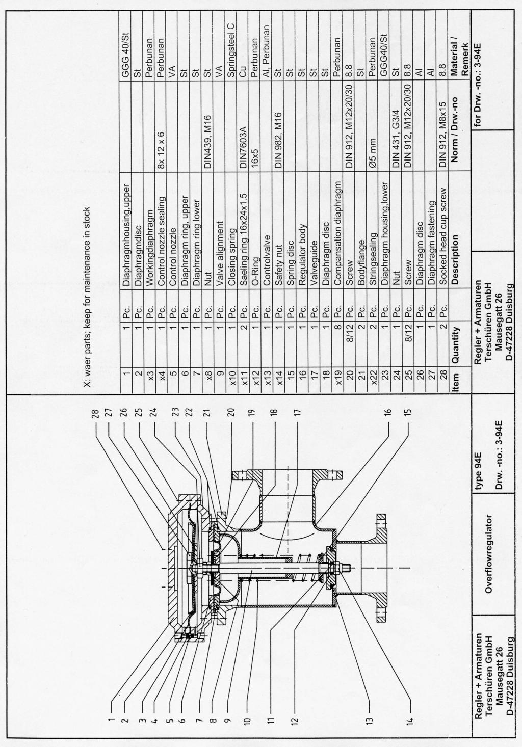
4 Design and Function of Type 94E (94) Overflow Regulator External Control Nozzel Installation All overflow regulators can be installed vertically or horizontally in flow direction. If installed vertically it is only necessary to mount the control regulator vertical beneath the control gear. Only qualified personal is allowed to do start up and maintenance. For demounting of the regulator all parts must be pressureless. Seite 4
5 Design As example for all overflow regulators type 94E is shown beneath with control regulator (I) and control gear (II). The control regulator is available in UH/UN/DUH/DUN and DH/DN for pressure range up to 1 bar respectively 7,5 bar. Control regulator RUHH is used for operating pressure greater than 7,5 bar. Scope of application Protection of compressor discharge pressure in overpressure range (conrol regulator UH/UN). Function Inlet pressure (p e ) is applied under cone valve 5 and as well via control pipe 4 on compensation diaphragm 3 and under working diaphragm 1; via throttle 2 also in the upper chamber of the diaphragm. When starting up the compressor, that means increasing inlet pressure, overflow regulator opens because the pressure above working diaphragm 1 increases less fast than in the lower diaphragm chamber due to throttle 2. Cone valve 5 closes when the pressure in both diaphragm chambers has equalized. If inlet pressure, which reaches control regulator via control pipe 8 exceeds the set value of adjustment spring 13, control valve 7 opens and allows gas to flow from upper diaphragm chamber through control pipe 6. This creates a differential pressure at working diaphragm 1, which causes cone valve 5 to open. Discharge pressure is set by using hand wheel 10. Turning it to the right increases pressure. Starting apparatus After properly installing the regulator proceed as follows for start up: Release tension of adjustment spring in control regulator Close pressure side shut-off valve Start up compressor Slowly tension adjustment spring of control regulator until desired discharge pressure is reached Secure hand wheel with locknut The overflow regulator is ready for operation. Slowly open pressure side shut-off valve again. Attention The line connection of the ventilation hole must end outside in the open air. Because in case of a crack at the diaphragm, witch belongs to the control regulator, it will be possible, that gas flow through the line connection of the ventilation hole. The valve flow coefficient K G is the value of the flow rate q through fully opened control regulator while p e = bar abs. and p a = bar abs.; measured under standard conditions on a test bench with air as flow medium. Valve flow coefficient K G for overflow regulator type (related to air) Valve-Ø [mm] K G - value [Nm³/h] Valve-Ø [mm] K G - value [Nm³/h] Values for larger valve diameters available on request. The following equations enable to calculate the required K G value: K G - value at subcritical pressure ratio pa qn 053, : KG = [Nm³/h] pe a e a p ( p p ) (q n in [Nm³/h]; p e and p a in [bar abs.]) K G - value at supercritical pressure ratio pa qn 2 < 053, : KG = [Nm³/h] pe pe When other gases are used, it is necessary to convert q n with the following corrective factors f: Medium f Medium f Ammonia 1,30 Methane 1,35 Butane 0,69 Municipal gas 1,53 C0 2 0,81 Oxygen 0,94 Nat. gas L 1,26 Nitrogen 1,01 Air 1,30 Hydrogen 3,92 Values for other mediums available on request. Conversion equation: q n qnmedium = [Nm³/h] f Calculation of nominal connection with: qn 13, ( 273+ T) D [mm] min = p v max q n : [Nm³/h]; p : [bar abs.]: v max : [m/s]; T : [ C] v max = max. permissible flow velocity Optimum valve diameter and nominal connection width can be calculated for each medium and unit with a computer program in our office. Unit Layout Seite 5
6 Overflow regulator Type 92/92E Scope of Application - Securing discharge pressure in overpressure range (Control regulator UH/UN) - Securing intake pressure in overpressure range (Control regulator DH/DN) Function Inlet pressure (pe) is applied under cone valve 5 and as well via control pipe 4 on compensation diaphragm 3 and under working diaphragm 1; via throttle 2 also in the upper chamber of the diaphragm. When starting up the compressor, that means increasing inlet pressure, overflow regulator opens because the pressure above working diaphragm 1 increases less fast than in the lower diaphragm chamber due to throttle 2. Cone valve 5 closes when the pressure in both diaphragm chambers has equalized. Securing discharge pressure: If inlet pressure, which reaches control regulator via control pipe 8 exceeds the set value of adjustment spring 13, control valve 7 opens and allows gas to flow from upper diaphragm chamber through control pipe 6. This creates a differential pressure at working diaphragm 1, which causes cone valve 5 to open. Discharge pressure is set by using hand wheel 10. Turning it to the right increases pressure. Securing intake pressure: If compressor intake pressure, which reaches under diaphragm 17 of control regulator DH via control pipe 18 falls below the set value of adjustment spring 15, control valve 19 opens and allows gas to flow from upper diaphragm space via control pipe 6. This creates a differential pressure at working diaphragm 1, which causes cone valve 5 to open. Intake pressure is set by using hand wheel 14. Turning it to the right increases pressure. Starting apparatus After properly installing the regulator proceed as follows for start up: - Open shut-off valve on compressor intake side - Close pressure side shut-off valve - Close control regulator DH for intake pressure, meaning relax adjustment spring completely - Open control regulator UH for discharge pressure, meaning relax adjustment spring completely - Start up compressor - Set discharge pressure at control regulator UH as for type 94 - Do not switch off compressor - Slightly open shut-off valve on pressure side - Slowly close the shut-off valve on intake side until the desired intake pressure is reached - Slowly tension (turn to right) adjustment spring of control regulator DH until switch point is reached - Secure handwheel with locknut The overflow regulator is ready for operation. Slowly open intake and pressure side shut-off valves again. Seite 6
7 Overflow Regulator Type 95/95E Scope of Application - Securing discharge pressure in overpressure range (Control regulator UH/UN) - Securing intake pressure in underpressure range (Control regulator DUH/DUN) Function Inlet pressure (pe) is applied under cone valve 5 and as well via control pipe 4 on compensation diaphragm 3 and under working diaphragm 1; via throttle 2 also in the upper chamber of the diaphragm. When starting up the compressor, that means increasing inlet pressure, overflow regulator opens because the pressure above working diaphragm 1 increases less fast than in the lower diaphragm chamber due to throttle 2. Cone valve 5 closes when the pressure in both diaphragm chambers has equalized. Securing discharge pressure: If inlet pressure, which reaches control regulator via control pipe 8 exceeds the set value of adjustment spring 13, control valve 7 opens and allows gas to flow from upper diaphragm chamber through control pipe 6. This creates a differential pressure at working diaphragm 1, which causes cone valve 5 to open. Discharge pressure is set by using hand wheel 10. Turning it to the right increases pressure. Securing intake pressure: If compressor intake pressure, which reaches above diaphragm 17 of control regulator DUH via control pipe 18 exceeds the set value of adjustment spring 15, control valve 19 opens and allows gas to flow from upper diaphragm space via control pipe 6. This creates a differential pressure at working diaphragm 1, which causes cone valve 5 to open. Intake pressure is set by using hand wheel 14. Turning it to the right increases underpressure. Starting apparatus After properly installing the regulator proceed as follows for start up: - Open shut-off valve on compressor intake side - Close pressure side shut-off valve - Close control regulator DUH for intake pressure, meaning tension adjustment spring - Open control regulator UH for discharge pressure, meaning relax adjustment spring - Start up compressor - Set discharge pressure at control regulator UH as for type 94 - Do not switch off compressor - Slightly open shut-off valve on pressure side - Slowly close the shut-off valve on intake side until the desired intake pressure is reached - Slowly relax (turn to left) adjustment spring of control regulator DH until control regulator switch point is reached - Secure handwheel with locknut The overflow regulator is ready for operation. Slowly open intake and pressure side shut-off valves again. Seite 7
8 Overflow Regulator Type 96/96E Scope of Application - Securing intake pressure in underpressure range (Control regulator DUH/DUN) Function Inlet pressure (pe) is applied under cone valve 5 and as well via control pipe 4 on compensation diaphragm 3 and under working diaphragm 1; via throttle 2 also in the upper chamber of the diaphragm. When starting up the compressor, that means increasing inlet pressure, overflow regulator opens because the pressure above working diaphragm 1 increases less fast than in the lower diaphragm chamber due to throttle 2. Cone valve 5 closes when the pressure in both diaphragm chambers has equalized. If compressor intake pressure, which reaches above diaphragm 11 of control regulator DUH via control pipe 8 exceeds the set value of adjustment spring 13, control valve 7 opens and allows gas to flow from upper diaphragm space via control pipe 6. This creates a differential pressure at working diaphragm 1, which causes cone valve 5 to open. Intake pressure is set by using hand wheel 10. Turning it to the right increases underpressure. Starting apparatus After properly installing the regulator proceed as follows for start up: - Open shut-off valve on compressor intake side - Close control regulator DUH/DUN for intake pressure, meaning tension adjustment spring - Slightly open pressure side shut-off valve - Start up compressor - Slowly close the shut-off valve on intake side until the desired intake pressure is reached - Slowly relax (turn to left) adjustment spring of control regulator DH until control regulator switch point is reached - Secure handwheel with locknut The overflow regulator is ready for operation. Slowly open intake and pressure side shut-off valves again. Seite 8
9 Other Types, Variants und Accessories By combining the control regulators and different connection modes, additional regulator types for different applications can be realised. Special models and purposeful accessories allow a diverse range of tasks to be solved. Overflow Regulator Type 97E/97 Scope of Application Securing differential pressure between discharge and intake pressure. (Control Regulator DUH/DUN) Overflow Regulator Type 99E/99 Scope of Application Securing intake pressure In overpressure range (Control Regulator DH/DN) Hot Gas Model Diaphragm materials Perbunan und Viton limit the possibility of using the overflow regulator for high gas temperatures due to their lacking high temperature resistance. Therefore, for media temperatures above 180 C up to around 250 C, the hot gas model identified by the additional symbol H in type designation is used. The diaphragm housing is installed on the regulator housing using spacers so that the media temperature is not applied directly to the diaphragms Seite 9
10 Starting Relief The construction of starting relief is shown using overflow regulator type 94E as example. The additional attached 2/2-Way Solenoid Valve is currentless open. When starting the plant, the overflow regulator is forced to open by the opened solenoid valve and no impermissible overpressure can form on pressure side of the compressor. After the plant rated output (compressor speed) is reached, solenoid valve is closed by release of current and the overflow regulator moves into normal position. If control voltage fails the overflow regulator is forced open and thus realises the safety function for voltage drop. Primary Sound Absorption According to the pressure ratio of the overflow regulator high sound intensity can result during expansion. This expansion sound can be reduced approx db by installing a ring-shaped, spongy filling body around the cone valve. Subsequent installation in the works is also possible using hold down clamp 3 and allen screws 4. Blowout Silencer Blow out noise from overflow regulators opening into atmosphere, can effectively be reduced by a directly flange-mounted silencer. This sound absorber only generate low pressure drop and work in a relatively wide frequency range. They are designed for special application and attain sound reduction up to 20 db. Outlet-Flange L ABS [mm] Di [mm] Da [mm] DN > DN 150 Special Design Motor Controled Set Value Adjustment For applications with changing pressure ratios or plants with changing operating modes the controldevice of the overflow regulator can be equipped with a motor actuator instead of the hand wheel. Using the motor drive, set value of the control regulator and with this response pressure can be varified while running plant. Seite 10
11 External Control Nozzle External control nozzle is used when: - soiling and blockaging is expected or a moist gas is used, - steel diaphragm housing or control regulator RUHH is used, - an easier and faster accessibility to the control nozzle is required. The connections of the control nozzle are produced with Ermeto-Pipes 10L as a standard. Piston Valve K For gas pressure above 7,5 bar piston valve in combination with control regulator RUHH is used (addition K in type designation). The piston replaces the compensating diaphragm while having the same function and due to ist design it is capable to equalise large pressure ratios between supply and discharge pessure without deformation. Position Indicator The indicator for optical or electronic signalling of the valve position can be installed optional at each overflow regulator type. The position of the working diaphragm suspension is transferred mechanically to the indicator. The indicator can be fitted with a limit switch to generate an electronic signal e.g. for a control panel or a monitoring device. Changing Operating Modes or Gases By combining several control devices and cicuitry with solenoid valves it is possible to realise different pressures or operating cases with one overflow regulator. When handling e.g. two operating modes with a regulator type 94 the control device UH1 is set to the higher pressure and normally in function. Control device UH2 with a lower set value becomes active when solenoid valve MV is opened. In case of more than two operating modes or other regulator types adequate installation is required. Seite 11
12 Design Control Gear Special Maintenance Instructions Performing a maintenance the control gear has to be checked on sealed closure of cone valve 13, for wear of the diaphragms 3 and 18 and on tightness against atmosphere. Cone valve 13 is tight, if by running plant no remarkable temperature increase occurs or no audible overflow occurs (prescribed set value is not reached). To remove cone valve 13 first screws 25 have to be undone and diaphragm housing can be removed. After that working diaphragm 3 can be unscrewed. Releasing screws 19 compensating diaphragm 18 together with valve suspension 9, valve guide 7 and cone valve 13 can be removed as a whole. Now all wearing parts have to be replaced. When installing it is to insure that items 4, 11, 12, and 20 are exchanged too. Cone valve 13 has to stand centrally on the valve seat so that during the assembly compensator diaphragm 18 automatically centers itself in the lower diaphragm housing 23. When installing working diaphragm 3 the prescribed maximum valve run has to be achieved again. Following equation as a rule of thumb can be used: Valve Run [mm] = ValveØ [mm] 0,25 X The valve run is measured between working diaphragm suspension 27 and the upper diaphragm housing 1. Seite 12
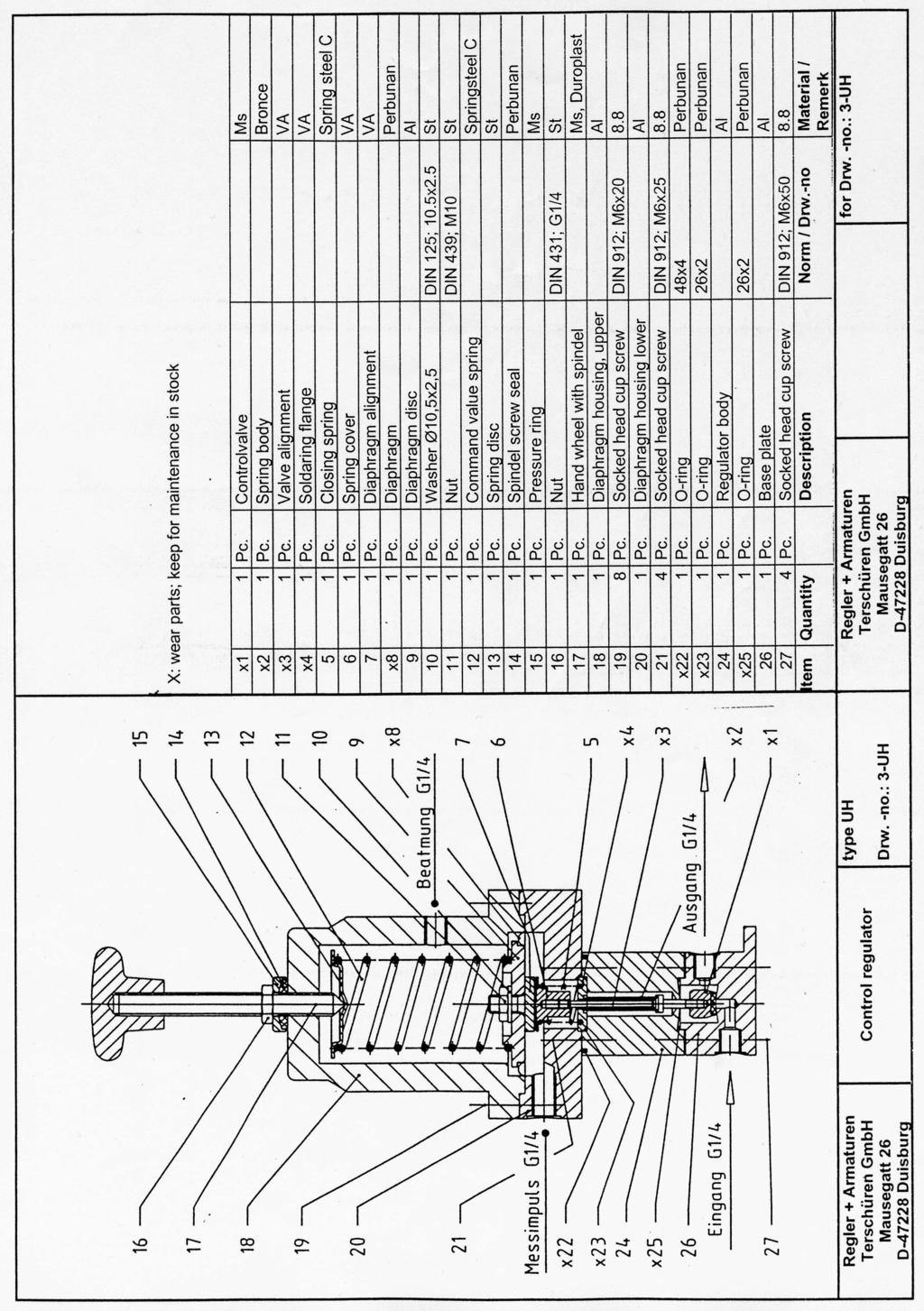
13 Special Maintenance Instructions Control Regulator Control Regulator For maintanance the control regulator has to be dismantled from the main device. Each time before taking apart the regulator, the adjustment spring 12 has to be relaxed by turning cross handle 17 to the left. Especially diaphragm 8, spring body 2, valve suspension 3, flange 4 and control valve 1 have to be checked for wear. By undoing screws 19 the diaphragm 8 with suspension 7 can be removed and checked. By unscrewing spring cap 6 and undoing screws 21 and 27 as well as nut 28 directly above the control valve 1 it can be unscrewed from controller set (2,3,4). The set can be removed and has to be checked. To maintain general operating safety the set should be replaced every three years latest. When installing it is to insure that items 4, 11, 12, and 20 are exchanged too. Cone valve 13 has to stand centrally on the valve seat so that during the assembly compensator diaphragm 18 automatically centers itself in the lower diaphragm housing 23. When installing working diaphragm 3 the prescribed maximum valve run has to be achieved again. Following equation as a rule of thumb can be used: The valve run is measured between working diaphragm suspension 27 and the upper diaphragm housing 1. When assembling it has to be ensured that: - control valve 1 is screwed up until approx. ¼ turns before the limit of the controller set (2,3,4), - spring cap 6 is only screwed on controller set (2,3,4) so wide that when pressing spring cap 6 the loosely placed regulator base 26 is lifted approx. 2 mm from the seat of regulator body 24 by control valve 1. Seite 13
14
15
16 COMPETENCE IN GAS! OUR PRODUCT PROGRAM DIN-DVGW Gas-Take Over Stations Gas-Regulaton Cabinets Station Accessories Gas-Pressure Regulators Safety Shut Off Valves Safety Relief Valves Overflow Regulatores Vaccum Regulatores Differential Pressure Regulators Special Design Regulators OUR ADMISS IONS Certified according to DIN EN ISO 9001 Production of Gas Stations DVG W (working paper) G493/1 Maintenance of Gas Stations DVG W (working paper) G493/2 W2 Armaturen GmbH Dr.-Alfred-Herrhausen-Allee 44a Duisburg, Germany T (020 65) F (020 65) info@w2-armaturen.de
GAS PRESSURE CONTROL UNIT TYPE 132
 GAS PRESSURE CONTROL UNIT TYPE 132 OUR DIVERSITY IS YOUR PROFIT. Gas Pressure Regulator Type 132 Scope of Application Scope of type 132 gas pressure regulator is to maintain the output pressure at a constant
Installation, Operating and Maintenance Manual Overflow Regulator Type 94/ 94 E
 Installation, Operating and Maintenance Manual Overflow Regulator Type 94/ 94 E Table of content 1. General information on installation, operating and maintenance instructions 1.1 Hazard notices 1.2 Qualified
Gas Pressure Regulator HON 200
 Product information serving the gas industry worldwide Applications, characteristics, technical data Application Gas supply to municipal, industrial and individual consumers Regulator for low-load rails
Gas Pressure Regulator HON 300
 Product information serving the gas industry worldwide Applications, characteristics, technical data Applications direct acting gas pressure regulator, for systems in accordance with DVGW working instruction
safety shut-off Valve HON 703 / HON 704
 safety shut-off Valve HON 703 / HON 704 Product information serving the gas industry worldwide Applications, characteristics, technical data Applications Main safety device in gas pressure regulating systems
Safety Shut-Off Valve HON 720
 Safety Shut-Off Valve HON 70 Product information serving the gas industry worldwide Application, Characteristics, Technical Data Application main safety device for gas pressure regulating stations suitable
safety Shut-Off Valve HON 721
 safety Shut-Off Valve HON 7 product information serving the gas industry worldwide safety shut-off valve HON 7 safety shut-off valve HON 7 Application, Characteristics, Technical Data Application safety
Actuator HON 670 / 671
 Actuator HON 670 / 67 Product information serving the gas industry worldwide Applications, characteristics, technical data Application The actuators HON 670 (K6, K8) and HON 67 (K7) are used to trigger
Safety Relief Valve HON 832
 Safety Relief Valve HON 832 product information serving the gas industry worldwide Application, characteristics, technical data Application 2 As leak gas SRV with internal vent connection (function class
Pressure Regulator 133 / 233
 Benefits Accurate regulation Exchangeable component technique Easy maintenance Suitable for HTB requirements DVGW-approval (DIN 3380/81, VP 200). Description The 133/233 regulator is a direct-acting, spring
HON 219 Pressure Reducer (D119a)
") Product information serving the gas industry worldwide Applications, characteristics, technical data Applications For industrial and process application Suitable for gases in accordance with DVGW Worksheet
Product information serving the gas industry worldwide Applications, characteristics, technical data Applications For industrial and process application Suitable for gases in accordance with DVGW Worksheet
Ball valve HKSF-W100. Ball valve HKSF-W100. RMA Kehl GmbH & Co. KG Oststrasse 17 D Kehl / Germany
 Ball valve HKSF-W100 RMA Kehl GmbH & Co. KG Oststrasse 17 D-77694 Kehl / Germany info@rma-kehl.de www.rma-armaturen.de 1 Design Features: RMA-ball valves type HKSF-W are fully welded and completely maintenance-free
Mounting and Operating Instructions EB 3007 EN. Self-operated Pressure Regulators. Differential Pressure Regulators (opening) Type Type 42-25
 Type Type 42-25") Self-operated Pressure Regulators Differential Pressure Regulators (opening) Type 42-20 Type 42-25 Type 42-20 Differential Pressure Regulator Type 42-25 Differential Pressure Regulator Mounting and Operating
Self-operated Pressure Regulators Differential Pressure Regulators (opening) Type 42-20 Type 42-25 Type 42-20 Differential Pressure Regulator Type 42-25 Differential Pressure Regulator Mounting and Operating
2/2-Way Solenoid Control Valve
 2/2-Way Solenoid Control Valve Excellent range (1:200) Very good response Compact valve design Orifice sizes 0.05... 2.0 mm Port connection 1/8 or sub-base Type 2871 can be combined with Type 8605 Digital
PRESSURE REGULATOR LBM SERIES
 VIRTUAL CATALOGUE FAIL TO OPEN REGULATOR HIGH FLOW COEFFICIENT WIDE PRESSURE-REGULATION RANGE FAST RESPONSE PRESSURE REGULATOR LBM SERIES FULL SEAL AT ZERO FLOW CAN BE SUPPLIED WITH MINIMUM / MAXIMUM PRESSURE
Pilot HON 625. Entwurf. Product information. serving the gas industry worldwide
 Pilot HON 62 Entwurf Product information serving the gas industry worldwide Pilot HON 62 Application, characteristics Application Pilot for the gas pressure regulator HON 02 Pilot for outlet pressure control
RR 16 Commercial & Industrial Regulator
 Gas RR 16 Commercial & Industrial Regulator Applications The RR 16 regulator is designed for industrial use: gas supply networks, district stations, industries, heating plants, as well as for all installations
FRM. Medium Pressure Regulator. Medium pressure regulator Type FRM
 FRM Medium Pressure Regulator Medium pressure regulator Type FRM Direct acting pressure regulator with adjustable setpoint springs and modular mounted safety shutoff valve (SAV) In compliance with EN 334
Differential Pressure Regulator Type Type 45-6 (0.1 to 1 bar, DN 15) Mounting and Operating Instructions EB 3226 EN
 Mounting and Operating Instructions EB 3226 EN") Differential Pressure Regulator Type 45-6 Type 45-6 (0.1 to 1 bar, DN 15) Mounting and Operating Instructions EB 3226 EN Edition March 2008 Contents Contents Page 1 Design and principle of operation...................
Differential Pressure Regulator Type 45-6 Type 45-6 (0.1 to 1 bar, DN 15) Mounting and Operating Instructions EB 3226 EN Edition March 2008 Contents Contents Page 1 Design and principle of operation...................
Gas Pressure Regulator R 51
 Gas Pressure Regulator R 51 Product Information Subject to technical modifications! Reprint prohibited! Table of Contents Application, Features, Technical Data 4 Application 4 Features 4 Type of model
Gas Pressure Regulator HON 502
 Gas Pressure Regulator HON 502 Product information serving the gas industry worldwide Gas Pressure regulator HON 502 Application, Characteristics, Technical Data Application for offtake stations in gas
ASX 176 Axial Pressure regulator
 ASX 176 Axial Pressure regulator ASX 176 Classification and Area of Application ASX 176 is a downstream pressure regulator, pilot controlled, for medium and high pressure applications. It is particularly
Pressure reducing valves Index
 Index General information page Introduction 506 General introduction 507 for a steam plant 509 Product information BSP thread page Brass 510 ; BSP female thread 511 ; BSP male thread 513 Stainless steel
OPERATING INSTRUCTIONS
 0/05 OPERATING INSTRUCTIONS for gas pressure regulators PN0 with integrated slam shut valve (SSV) and integrated limited capacity safety relief valve (RV) MR 25 F0, MR 25 SF0 p e 20 kpa - 0 MPa (0,2-0
Pressure and Flow Control Valves DBGM, German and European Patents
 Pressure and Flow Control Valves DBGM, German and European Patents Absolutely Reliable Pressure and Flow Control In water mains of sizes DN 50 to DN 150, ERHARD Control Valves in straight or angle pattern
Pressure relief valve DHV 716 set range: 0,5-10,0 bar
 Pressure relief valve DHV 7 set range: 0,5-0,0 bar Advantage pressure setting possible at any time, also during operation optimum monitoring valves high reproducibility of the set pressure high level of
Compact pressure switches for gas and air
 Compact pressure es for gas and air / 5.0 Printed in Germany Edition 0.8 Nr. 9 544 6 Technical description The pressure is an adjustable compact pressure according to EN 854 for combustion plants. The
Pressure relief valve DHV 712 DN 65-80: 0,5-10 bar, DN : 0,3-4 bar, DN 100: 0,5-6 bar
 Pressure relief valve DHV 7 DN 5-80: 0,5-0 bar, DN 5-00: 0, - bar, DN 00: 0,5 - bar Advantage for high pressure stability reliable reduction of pressure peaks and pulsations pressure setting possible at
RR 16 Commercial & Industrial Regulator
 RR 16 Commercial & Industrial Regulator The RR 16 regulator is designed for industrial use: gas supply networks, district stations, industries, heating plants, as well as for all installations where accurate
GasMultiBloc Combined regulator and safety valve Infinitely variable air/ gas ratio control mode MBC-300-VEF MBC-700-VEF MBC-1200-VEF
 GasMultiBloc Combined regulator and safety valve Infinitely variable air/ gas ratio control mode MBC-00-VEF 7.03 Max. operating pressure 30 mbar Compact design High flow values Low weight Low power consumption
Universal Charging and Testing Unit FPU-1
 1. DESCRIPTION 1.1. FUNCTION The charging and testing unit FPU-1 is used to charge accumulators with nitrogen or to check or to change the existing pre-charge pressure in accumulators. For this purpose
Safety Shut-off Valve SSV
 Safety Shut-off Valve SSV 8200-8300 < Accurate operation < Compact design < Easy maintenance Applications The safety shut-off valve is designed for use in gas distribution, and pressure regulation systems.
Mounting and operating instructions EB 2530 EN. Self-operated Pressure Regulator. Pressure Reducing Valve Type M 44-2
 Self-operated Pressure Regulator Pressure Reducing Valve Type M 44-2 Type M 44-2, connection G 1 4, K VS = 0.15 Type M 44-2, connection G 1, K VS = 6 Fig. 1 Type M 44-2 Pressure Reducing Valve Mounting
SAV. Safety Shut-off Valve. Safety Shut-off Valve Type SAV
 SAV Safety Shut-off Valve Safety Shut-off Valve Type SAV Direct acting shut-off device with adjustable setpoint springs for over-pressure and underpressure monitoring In compliance with EN 14382 Inlet
Pressure Reducing Valve DMV 750 set range: bar
 Pressure Reducing Valve DMV 750 set range:.0-6.0 bar Advantage pressure setting possible at any time, also during operation hermetically sealed by valve diaphragm high level of operating safety and long
2/2-Way Solenoid Control Valve
 2/2-Way Solenoid Control Valve Excellent range (1:200) Very good response Compact valve design Orifice sizes 0.05... 2.0 mm ort connection 1/8 or sub-base Type 2871 can be combined with Type 8605 Digital
Components for air preparation and pressure adjustment. OUT port position ( ) connected Rear side. of IN port. Air tank. directly.
 connected Rear side. of IN port. Air tank. directly.") Components preparation and pressure adjustment ABP Overview ABP is a component that enables boosting by s only up to twice primary pressure (.0MPa max.) in combination with using air tank but not using
Components preparation and pressure adjustment ABP Overview ABP is a component that enables boosting by s only up to twice primary pressure (.0MPa max.) in combination with using air tank but not using
MV-01. Features. 2/2-way Solenoid Valve for Fluids. Description: Application:
 MV-01 2/2-way Solenoid Valve for Fluids Description: Features / Nominal diameters 1/4-2 / Pressure up to 10 bar / 24 V DC and all common AC variants / Forced-lifting The pilot-controlled full-way valve
Tightness controls TC 1 3 and TC 4
 Tightness controls TC 1 3 and TC 4 Test of both safety valves Short test period thanks to logical decision-making in the program sequence Adjustable test period which can be adapted to different systems
Aperval Pressure Regulators
 Pressure Regulators Pressure regulators is pilot-controlled pressure regulator for medium and low pressure applications. is normally a fail to open regulator and specificaly will open under the following
DN 50 REGULATOR SUTON 5000A1 REGULATOR SUTON 5000D1
 www.apq.com.es EU Product / Spain DN 50 REGULATOR SUTON 5000A1 REGULATOR SUTON 5000D1 Cod. RISUT5000A1 Cod. RISUT5000D1 DESCRIPTION The Suton 50001 Regulator is designed for use in distribution networks
Differential pressure and flow controller (PN 16) AVPQ - return mounting, adjustable setting
 AVPQ - return mounting, adjustable setting") Data sheet Differential pressure and flow controller (PN 16) AVPQ - return mounting, adjustable setting Description AVPQ is a self-acting differential pressure and flow controller primarily for use in
Data sheet Differential pressure and flow controller (PN 16) AVPQ - return mounting, adjustable setting Description AVPQ is a self-acting differential pressure and flow controller primarily for use in
Tubes Components Valves Units Engineering SO EVERYTHING KEEPS FLOWING. Safety valves Bunging valves Vacuum valves Tank dome fittings
 SO EVERYTHING KEEPS FLOWING Safety valves Bunging valves Vacuum valves Tank dome fittings Reliable reaction at the right moment Safety components are part of our everyday life. Like anti-skid systems in
Safety shut-off valve S 50. Product information
 Safety shut-off valve S 50 Product information Subject to modifications! Reprint prohibited! Table of Contents Application, Characteristics, Technical Data 4 Application 4 Characteristics 4 Type of model
E 158 E 198 E 248. Tank top mounting Connection up to G11 / 4 Nominal flow rate up to 250 l/min e d
 R e t u r n - S u c t i o n F i l t e rs E 158 E 198 E 248 Tank top mounting Connection up to G11 / 4 Nominal flow rate up to 250 l/min 20.90-5e 0.0-2d D e s c r i p t i o n Application For operation in
Mounting and Operating Instructions EB 2558 EN. Self-operated Pressure Regulators. Type Pressure Build-up Regulator
 Self-operated Pressure Regulators Type 2357-31 Pressure Build-up Regulator with safety function and integrated excess pressure valve Type 2357-31 with non-return unit at port C Ports A and B with soldering
Pressure relief valve DHV 725 set range: 0,2-10,0 bar
 Pressure relief valve DHV 75 set range: 0, - 0,0 bar Advantage pressure setting possible at any time, also during operation optimum monitoring valves high reproducibility of the set pressure high level
Pressure Reducing Valve DMV 755
 Pressure Reducing Valve DMV 755 Nominal size DN 10 50 Nominal size 3/8 2 Nominal pressure PN 10 bar Features pressure setting range 1 to 9 bar control valve for reliable reduction of system pressures to
HON HSV086 Series Safety Shut-off Valves for Efficient, Sustainable and Safe Gas Distribution. Proven Technology. Superior Performance.
 HON HSV086 Series Safety Shut-off Valves for Efficient, Sustainable and Safe Gas Distribution Proven Technology. Superior Performance. HON HSV086 and HON HSVS086 Series Valves Designed to offer overpressure
776 Cryogenic Safety Valve
 776 Cryogenic Safety Valve INTRODUCTION 776 Cryogenic Safety Valve The effects of exceeding safe pressure levels in an unprotected pressure vessel or system, can have catastrophic effects on both plant
RB 4700 Commercial & Industrial Regulator
 RB 4700 Commercial & Industrial Regulator The RB 4700 regulator is designed for use in industrial and distribution applications such as district station and heating plants, and for industrial customers.
Norval Pressure regulator
 Norval Pressure regulator NORVAL Classification and Field of Application The NORVAL is a downstream pressure regulator, self actuated, spring loaded for medium and low pressure applications. It is suitable
T 2523 EN Type 2406 Excess Pressure Valve Self-operated Pressure Regulators ANSI version
 T 2523 EN Type 2406 Excess Pressure Valve Self-operated Pressure Regulators ANSI version Application Excess pressure valve for set points from 0.075 to 150 psi (5 mbar to 10 bar) Valve size NPS ½ to 2
Mass Flow Controller (MFC) for Gases
 for Gases") Mass Flow Controller (MFC) for Gases Type 8713 can be combined with... Direct flow measurement by MEMS- Technology for nominal flow rates from 1 ml N /min to 8 l N /min (N 2 ) High accuracy and repeatability
Mass Flow Controller (MFC) for Gases Type 8713 can be combined with... Direct flow measurement by MEMS- Technology for nominal flow rates from 1 ml N /min to 8 l N /min (N 2 ) High accuracy and repeatability
AVP-F. p setting range (bar) Code No. 003H6200
 Code No. 003H6200") Data sheet Differential pressure controller (PN 16) AVP - return and flow mounting, adjustable setting AVP-F - return mounting, fixed setting Description The controller has a control valve, an actuator
Data sheet Differential pressure controller (PN 16) AVP - return and flow mounting, adjustable setting AVP-F - return mounting, fixed setting Description The controller has a control valve, an actuator
Tank Blanketing Regulators
 Tank Blanketing Regulators Low-Pressure Reducing Regulator Type BR Low-Pressure Relief Valve Type BS Description Tank blanketing, or padding, is the process and practice of covering a stored commodity,
Type 310A-32A Pressure Reducing Regulator and Type 310A-32A-32A Working Monitor Regulator
 January 2009 Type 310A-32A Pressure Reducing Regulator and Type 310A-32A-32A Working Monitor Regulator Introduction The Type 310A pilot-operated high-pressure regulator (Figure 1) is used where high capacity
Self-operated Pressure Regulators Type 2405 Pressure Reducing Valve
 Self-operated Pressure Regulators Type 2405 Pressure Reducing Valve ANSI version Application Pressure reducing valve for set points from 0.075 to 150 psi (5 mbar to 10 bar) Valve size NPS ½ to 2 1) (DN
Mounting and Operating Instructions EB 3007 EN. Self-operated Pressure Regulators. Type Type Differential Pressure Regulators (opening)
") Self-operated Pressure Regulators Type 42-20 Type 42-25 Differential Pressure Regulators (opening) Translation of original instructions Type 42-20 Differential Pressure Regulator Type 42-25 Differential
Self-operated Pressure Regulators Type 42-20 Type 42-25 Differential Pressure Regulators (opening) Translation of original instructions Type 42-20 Differential Pressure Regulator Type 42-25 Differential
GRUNDFOS alldos product information. Vaccuperm 111 / 113. Vacuum gas dosing systems for chlorine gas, ammonia, sulphur dioxide and carbon dioxide
 GRUNDFOS alldos product information Vacuum gas dosing systems for chlorine gas, ammonia, sulphur dioxide and carbon dioxide Construction and function Modular system Vacuum regulator for direct mounting
RTG 311 pressure regulators are included within the direct acting and balanced valve regulator class.
 Introduction RTG 311 pressure regulators are included within the direct acting and balanced valve regulator class. The regulator is used for reducing and regulating the pressure of natural gases and LPG,
RTG 25. Introduction
 Introduction RTG 25 pressure regulator is included within the direct acting and balanced valve regulator class. These regulators have a large range of applications both in industrial and domestic installations.
Safety shut-off valve Control Control Lock-up Over pressure set point Under pressure set point pressure range accuracy class
 MR HP20 Gas pressure regulator Inlet pressure 20 bar Nominal diameter DN 25, DN 50, DN 80, DN 100 Applications Pressure reduction for: - District distribution - Industrial uses Brief information The gas
General Catalogue MEDENUS
 General Catalogue MEDENUS 11.2016 1 List of abbreviations and formula symbols ATC acceptance test certificate BV Vent valve nominal size DVGW Deutsche Vereinigung des Gas- und Wasserfaches e.v. f conversion
Safety shut-off valve S 100. Product information
 Safety shut-off valve S 100 Product information 03.2017 Subject to modifications! Reprint prohibited! Table of Contents Application, Characteristics, Technical Data 4 Application 4 Characteristics 4 Type
Differential pressure controller (PN 16) AHP - return mounting, adjustable setting
 AHP - return mounting, adjustable setting") Data sheet Differential pressure controller (PN 16) AHP - return mounting, adjustable setting Description DN 15-40 DN 50 DN 65-100 AHP is a self-acting differential pressure controller primarily for use
Data sheet Differential pressure controller (PN 16) AHP - return mounting, adjustable setting Description DN 15-40 DN 50 DN 65-100 AHP is a self-acting differential pressure controller primarily for use
Safety Shut-Off Valve RMG 711
 Safety Shut-Off Valve RMG 711 Product information serving the gas industry worldwide Application, Features, Technical Data Application safety device for gas pressure regulating stations suitable for natural
Mass Flow Controller (MFC) for Gases
 for Gases") Mass Flow Controller (MFC) for Gases Bypass MFC with capillary technology for nominal flow rates from 5 ml N /min to 15 l N /min Applicable for aggressive gases Compact design and digital communication
Mass Flow Controller (MFC) for Gases Bypass MFC with capillary technology for nominal flow rates from 5 ml N /min to 15 l N /min Applicable for aggressive gases Compact design and digital communication
Self-operated Regulators Accessories Differential Pressure and Flow Regulators
 Self-operated Regulators Accessories Differential Pressure and Flow Regulators Compression-type fittings Needle valves Compensation chambers Orifice plates Welding neck flanges Control lines Application
Gas Pressure Regulator HON 505
 product information serving the gas industry worldwide Application, Characteristics, Technical Data Application for gas supply for natural gas and all non-corrosive gaseous media Characteristics compact
Series 42 Self-operated Regulators Differential Pressure Regulators with Type 2424/Type 2428 Actuator (closing) Type Type 42-28
 Type Type 42-28") Series 42 Self-operated Regulators Differential Pressure Regulators with Type 2424/Type 2428 Actuator (closing) and balanced Type 2422 Valve Type 42-24 Type 42-28 Application Differential pressure regulators
Series 42 Self-operated Regulators Differential Pressure Regulators with Type 2424/Type 2428 Actuator (closing) and balanced Type 2422 Valve Type 42-24 Type 42-28 Application Differential pressure regulators
The affordable consumption counter for compressed air and gases R 3 /4 (DN 20)
") VA 420 new The affordable consumption counter for compressed air and gases R 1 /4 (DN 8) DN 15 R 3 /4 (DN 20) DN 25 R 1 1 /4 (DN 32) DN 40 R 2 (DN 50) With mit und and ohne without Flansch flange Intelligent
VA 420 new The affordable consumption counter for compressed air and gases R 1 /4 (DN 8) DN 15 R 3 /4 (DN 20) DN 25 R 1 1 /4 (DN 32) DN 40 R 2 (DN 50) With mit und and ohne without Flansch flange Intelligent
Paul Ladage 26 September 2017 MOVING THINGS AROUND - LATEST TRENDS IN HONEYWELL FLAGSHIP REGULATORS
 Paul Ladage 26 September 2017 MOVING THINGS AROUND - LATEST TRENDS IN HONEYWELL FLAGSHIP REGULATORS Agenda 1 What do we sell? Flagship Products HON 5020 HON R100 NG HON 512, class 150 Q&A Where Do Honeywell
better measurement Simply a question of SCHMIDT Flow Sensor SS The cost-effective alternative in pressurised systems up to 10 bars.
 Simply a question of better measurement SCHMIDT Flow Sensor SS 20.261 The cost-effective alternative in pressurised systems up to 10 bars. Compressed air technology Industrial processes A cost analysis
PRESSURE REDUCING VALVE RP45 (EN)
") PRESSURE REDUCING VALVE RP45 (EN) DESCRIPTION The ADCA RP45 series pressure reducing valves are single seat bellows sealed controllers, operating without auxiliary energy, designed for use on steam, compressed
PRESSURE REDUCING VALVE RP45 (EN) DESCRIPTION The ADCA RP45 series pressure reducing valves are single seat bellows sealed controllers, operating without auxiliary energy, designed for use on steam, compressed
Operating instructions - Translation of the original -
 Operating instructions - Translation of the original - 5093 xxx 000-xxx Check valve DN25 - DN100 EPDM O-Ring-design Intermediate flanged with welding ends 27.1.12 KIESELMANN GmbH Paul-Kieselmann-Str.4-10
Differential pressure controller (PN 25) AVP - return and flow mounting, adjustable setting
 AVP - return and flow mounting, adjustable setting") Differential pressure controller (PN 25) AVP - return and flow mounting, adjustable setting Description AVP(-F) is a self-acting differential pressure controller primarily for use in district heating systems.
Differential pressure controller (PN 25) AVP - return and flow mounting, adjustable setting Description AVP(-F) is a self-acting differential pressure controller primarily for use in district heating systems.
Combined Pressure / Vacuum Relief Valve KITO VD/o
 KITO VD/o DN D H kg* vacuum setting (mbar) pressure DIN ANSI DIN ANSI min max min max** 50 PN 16 2 220 332 351 11 3 50 10 75 80 PN 16 3 260 367 387 145 3 50 10 70 100 PN 16 4 260 368 393 178 3 50 10 80
Pressure reduction controller (PN 16, 25, 40)
") Pressure reduction controller (PN 16, 25, 40) AFD / VFG 2( - for water AFD / VFGS 2 - for steam Description The controller has a control valve, an actuator with one control diaphragm and a spring for pressure
Pressure reduction controller (PN 16, 25, 40) AFD / VFG 2( - for water AFD / VFGS 2 - for steam Description The controller has a control valve, an actuator with one control diaphragm and a spring for pressure
STAINLESS STEEL LOW PRESSURE REDUCING VALVE LPRV ELITE
 MAIN CHARACTERISTICS The stainless steel LPRV elite low pressure reducer is intended for the pressure reduction of the fluids such as water, air, clear liquids not in charge of and the compatible gases
Pressure Reducing Valve DMV 750
 ASV Stübbe GmbH & Co. KG Hollwieser Straße 5 D-32602 Vlotho Fon +49 (0) 57 33-7 99-0 Fax +49 (0) 57 33-7 99-2 00 www.asv-stuebbe.de contact@asv-stuebbe.de Pressure Reducing Valve DMV 750 Advantages reduction
Overview of types. T5-R B2/R B2 en v Subject to changes 1 / 4. k vs (Sequence 2)
") Technical data sheet R3015-..-..-B2 / R3020-..-..-B2 Characterised control valves, 6-way, with internal threads Two sequences (cooling/heating) With a rotary actuator 90 Water-side switching or modulating
Technical data sheet R3015-..-..-B2 / R3020-..-..-B2 Characterised control valves, 6-way, with internal threads Two sequences (cooling/heating) With a rotary actuator 90 Water-side switching or modulating
Mounting and Operating Instructions EB 3017 EN. Self-operated Regulators
 Self-operated Regulars Flow and Differential Pressure Regular Type 42-37 Flow and Differential Pressure or Flow and Pressure Regular Type 42-39 Type 42-37 Type 42-39 Fig. 1 Flow and differential pressure
2-Port Seat Valves with Flange, PN 16
 4 45 2-Port Seat Valves with Flange, PN 6 VVF45... dular cast iron EN-GJS-400-5 valve body DN 50...50 k vs 9...00 m /h Can be equipped with SKB...- or SKC...- electrohydraulic actuators Use For use in
Tightness control TC. Product brochure GB 3 Edition AGA
 Tightness control TC Product brochure GB 3 Edition 07.14 AGA Test of two safety valves Short test period thanks to logical decision-making in the program sequence Adjustable test period which can be adapted
2/2-way proportional valve
 2/2-way proportional valve High sensitivity Type can be combined with 0... 16 bar DN 0.8... 4 mm 1/8, 1/4 or sub-base EEx approvals optional Type 8605 Digital control electronics Cable plug version Type
Dival 600. Pressure Regulators
 Dival 600 Pressure Regulators Pressure regulators Dival 600 Dival 600 series pressure regulators are direct acting devices for low and medium pressure applications controlled by a diaphragm and counter
Gas Pressure Regulator RMG 201
 Product information serving the gas industry worldwide Application, characteristics, technical data Application application in industrial stations for small flowrate regulating lines in gas pressure regulating
Data sheet Pressure switch type CS December 2001 DKACT.PD.P10.A B1119
 Pressure switch type CS December 2001 DKACT.PD.P10.A2.02 520B1119 Introduction Pressure switch type CS is part of the Danfoss pressure control range. All CS pressure switches have a built-in pressure-operated,
ANDERSON GREENWOOD SERIES 9000 POSRV INSTALLATION AND MAINTENANCE INSTRUCTIONS
 Procedure-assembly-functional test and performance requirements 1 SCOPE 1.1 This document establishes the general procedure for assembly, functional testing and normal performance requirements of low Series
Flamco Flamco-Fill STA Flamco-Fill STM
 STA STM Typ STA 5936 Typ STM 5937 GB Installation and operating instructions 1999, 2 Contents GB UK Limited P.O. Box 9, Washway Lane, St. Helens, Merseyside WA10 6FE United Kingdom Telephone: 01744 744744
Flow VA 520. incl. temperature measurement. Intelligent solutions for ac- for compressed air and gases R 1/4 (DN 8) DN 15 R 3/4 (DN 20) DN 25
 DN 15 R 3/4 (DN 20) DN 25") VA 520 incl. temperature R 1/4 (DN 8) DN 15 R 3/4 (DN 20) DN 25 R 1 1/4 (DN 32) DN 40 R 2 (DN 50) Intelligent solutions for ac- for compressed air and gases work according to the approved calorimetric
VA 520 incl. temperature R 1/4 (DN 8) DN 15 R 3/4 (DN 20) DN 25 R 1 1/4 (DN 32) DN 40 R 2 (DN 50) Intelligent solutions for ac- for compressed air and gases work according to the approved calorimetric
CLASS TLP Pressure Reducing Valve
 CLASS TLP Pressure Reducing Valve CLASS TLP Direct Acting Pressure Reducing Valve The Class TLP balanced direct acting pressure regulator is designed for use on installations that have varying inlet pressures
Type 3709 Pneumatic Lock-up Valve. Translation of original instructions. Mounting and Operating Instructions EB 8391 EN
 Type 3709 Pneumatic Lock-up Valve Translation of original instructions Mounting and Operating Instructions EB 8391 EN Edition July 2017 Note on these mounting and operating instructions These mounting
Old documentation - Only for your information! Product is not available anymore!
 Double solenoid valve Regulator and safety combination Infinitely variable floating operation DM-EF 07-7. Printed in Germany Rösler Druck Edition 0.0 Nr. 9 Flanges, pressure switches, line sockets, pulse
PRESSURE REGULATORS AND FLOWMETERS, ALL MEDICAL GASES
 PRESSURE REGULATORS ALL MEDICAL GASES In this section we propose our pressure regulators (FM series, MU and MERCURY ) and our Rs flowmeters for applications other than oxygen therapy (presented in the
PRO-50 Instrument Supply Regulator
 Features CRN Approved The PRO-50 Regulator has been granted a Canadian Registration Number. Sour Service Capability Available in NACE configurations that comply with NACE MR0175/MR0103. Environmental limits
Operating instructions - Translation of the original -
 Operating instructions - Translation of the original - Overflow valves Typ 5076 DN 10 - DN100 KIESELMANN GmbH Paul-Kieselmann-Str.4-10 D - 75438 Knittlingen +49 (0) 7043 371-0 Fax: +49 (0) 7043 371-125
Tank Blanketing Regulators
 Tank Blanketing Regulators Low-Pressure Reducing Regulator Type BR Low-Pressure Relief Valve Type BS Description Tank blanketing, or padding, is the process and practice of covering a stored commodity,