SCIENTIFIC DATA SYSTEMS, INC. Depth Tension Line Speed Panel. DTLS Manual
|
|
|
- Cornelia Burke
- 5 years ago
- Views:
Transcription
1 SCIENTIFIC DATA SYSTEMS, INC. Depth Tension Line Speed Panel DTLS Manual This document contains proprietary information. Copyright 2015 Scientific Data Systems, Inc. All rights reserved. 1 Depth Tension Line Speed Panel DTLS
2 DTLS Manual This document contains proprietary information. Copyright 2015 Scientific Data Systems, Inc. All rights reserved Bacor Road Houston, Texas 77084, USA Phone: Website: Created September 5, 2018 Windows is a registered trademark of Microsoft Corporation in the United States and/or other countries. All other product names are trademarks of their respective companies.
3 Table of Contents TABLE OF CONTENTS DTLS HARDWARE...5 INTRODUCTION...5 DEPTH PANEL OPERATION...5 FIG 1.1 DTLS FACE PLATE...7 FIG 1.2 DTLS REAR PLATE DTLS CONNECTOR WIRING...9 INTERCONNECTION CABLES DTLS METER PROGRAMING SETUP FOR DEPTH COUNTER SETUP FOR DEPTH COUNTER 2/ LINE SPEED SETUP OF LINE TENSION DTLS THROUGH WARRIOR SOFTWARE USB COMMUNICATIONS DTLS HARDWARE SCHEMATIC SCHEMATIC SCHEMATIC Fig 6.1 Schematic page Fig 6.2 Schematic page Fig 6.3 Schematic page Fig 6.4 PCB DTLS HARDWARE Depth Tension Line Speed Panel DTLS
4
5 Section 1 1 DTLS Hardware Introduction The Depth, Line Speed and Line Tension Panel uses three industrial process Meters to provide simultaneous digital readout of the three measurements. Meter 1 is setup in a counting mode and can accommodate virtually any encoder resolution. Meter 2 is setup in a rate \ counter indicator mode and runs from the same encoder signals as Meter 1. Meter 3 senses a 4-20 ma signal from a pressure transducer connected to the measure head weight indicator system. Meters for other types of line weight sensor are available. The panel is intended to be powered by a 12 volt battery and contains a power supply providing regulated 12.0 volts and 5.0 volts for indicator and encoder power. The panel also provides 12 volts excitation for the pressure transducer. The encoder pulses are converted to depth and direction signals and routed to the depth and line speed meters and are also buffered and output to the rear panel connectors for input to the logging system. A retransmitted 4-20 ma signal is also available at the rear panel also for input to the logging system. Depth Panel Operation Depth entries and alarm setup points are entered from the key pads of each meter. Depth1 meter contains the alarm for minimum depth. If the depth counter becomes less than this minimum, it will activate the depth alarm. Depth2/Line Speed meter contains the alarm for maximum line speed. If the line speed becomes greater than this maximum, it will activate the overspeed alarm. Depth2 meter will display both a depth and the line speed, which can be selected by pressing the DISP-key. Any of the alarms will activate an audible alarm, front panel LED, and a rear panel external connector. The audio alarm can be silenced for the duration of the cause of that 5 Depth Tension Line Speed Panel DTLS
6 alarm by pressing the ALM DIS button. Once the alarm condition has passed, the audio alarm will be enable again for the next alarm. To enter a new preset depth on either depth meter, press the P2-key of that meter. The last preset depth will be displayed. The key directly under each digit will change the value of that digit. After the desired changes have been made, press the E-Key to enter the value into preset depth memory. To update the depth to the preset value, press the R-key to reset the depth. To enter new alarm values on either depth meter, press the P1-key of that meter. After changes have been made, press the E-key to enter the value into preset alarm memory. To enter a new alarm value on the line tension meter, press the PAR-key. The F1-key and F2-key can then be used to change the value. Press the PAR-key again to store the new alarm value

7 Fig 1.1 DTLS Face Plate 7 Depth Tension Line Speed Panel DTLS

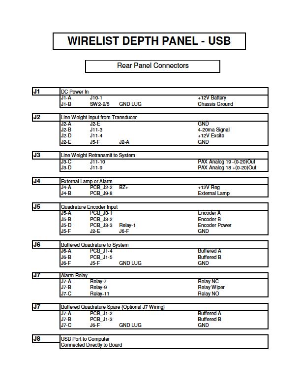
8 Fig 1.2 DTLS Rear Plate
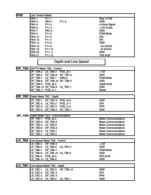
9 Section 2 2 DTLS Connector Wiring Interconnection Cables The cable to connect the depth panel buffered encoder output to the tool Interface panel has the following connections: Depth Panel 7 Pin Female Interface Panel 7 Pin Male The cable to connect the depth panel encoder input to the depth encoder has The following connections: Depth Panel 7 Pin Male Depth Encoder 7 Pin Female 9 Depth Tension Line Speed Panel DTLS
10 The cable for the retransmitted line tension from the depth panel to the system Tool interface panel has the following connections: Depth Panel 5 Pin Female Interface Panel 5 Pin Male The cable for the depth panel line tension input to the pressure transducer has The following connections: Depth Panel 5 Pin Male Pressure Transducer
11 Section 3 3 DTLS Meter Programing Setup for Depth Counter 1 Two sets of DIP switches must be set for proper function of the Depth meter. Switch one is located on the back of the meter. Switch two is located on the right side, as viewed from the front, (SW-1 ON Meter - 1, 4, 7, 8 ON/DOWN and 2, 3, 5, 6 OFF/UP) (SW-2 ON Meter - 1, 2 ON/DOWN and 3, 4, 5, 6, 7, 8, 9, 10 OFF/UP) Programming may only be accomplished by activating the `program enable switch at the rear of the panel. Other than changing the scale factor, reprogramming should only be necessary upon installation of a new meter. CODE ENTRY 41 1 Set unit personality to COUNTER 43 2 Set inputs to COUNT with UP/DOWN Control 44 1 Set to SINGLE EDGE COUNTING 45 2 Set scale multiplier to Set decimal point and leading zero blanking 51-2 Set reset mode to manual reset to preset 52-6 Set Output1 Alarm control to Boundry Set Output1 Time Delay to minimum 54 3 Set Output2 Termination to Terminate at Reset Set Output2 Time Delay to minimum 61 4 Set Right hand Dummy Zeros to None 66 2 Set 0perator enabled functions to Reset and Preset only 11 Depth Tension Line Speed Panel DTLS
12 With the settings above, to read out in feet (or meters) * Scale factor = 100 divided by encoder pulses per foot (or encoder pulses per meter) JP5 Setting 120 ppr 400 ppr 600 ppr 1200 ppr 1-2 No Divide / / / *Scale Factors - Note placing a sign in front of scale factor reverses encoder direction. Setup for Depth Counter 2/ Line Speed Two sets of DIP switches must be set for proper function of the Depth/Line Speed meter. Switch one is located on the back of the meter. Switch two is located on the right side, as viewed from the front, (SW-1 ON Meter - 1, 4, 7, 8 ON/DOWN and 2, 3, 5, 6 OFF/UP) (SW-2 ON Meter 1, 2,10 ON/DOWN and 3, 4, 5, 6, 7, 8, 9 OFF/UP) Programming may only be accomplished by activating the `program enable switch at the rear of the panel. Other than changing the scale factor, reprogramming should only be necessary upon installation of a new meter. CODE ENTRY 41 1 Set unit personality to RATE METER/COUNTER 42 3 Set Reset for both Rate and Counter 43 2 Set inputs to COUNT with UP/DOWN Control 44 1 Set to SINGLE EDGE COUNTING 45 2 Set scale multiplier to Set counter decimal point and leading zero blanking 51 1 Set Output1 to Rate and Output2 to Counter 52 6 Set Rate Alarm control to Boundry Set Rate Time Delay to minimum 54 3 Set Counter Termination to Terminate at Reset Set Counter Time Delay to minimum 56-2 Set Reset Counter to Preset Set Right hand Dummy Zeros to None 62 1 Set Time Rate to 1 Second 63 1 Set Rate Update Time 64 3 Set Rate Scale Multiplier to Set Rate decimal point and leading zero blanking 66 2 Set 0perator enabled functions to Reset and Preset only
13 With the settings above, to read out in feet per minute (or meters per minute) * Scale factor = 60 divided by encoder pulses per foot (or meter) JP5 Setting 120ppr 400ppr 600ppr 1200ppr 1-2 No Divide / / / Scale factor for the Depth 2 Counter is the same as the Depth 1 Counter above. Setup of Line Tension Programming may only be accomplished by activating the `program Enable switch at the rear of the panel. Press the PAR (Parameters) key to enter Program mode and select parameter groups. Use the F1 and F2 keys to change Selections 13 Depth Tension Line Speed Panel DTLS

14 Set each of the program groups as follows
15 4-SEC Secondary Function Parameters These parameters are not used at this time. 5-tOt Totalized Parameters These parameters are not used at this time. 6-SPt Setpoint Parameters Display Parameter Setting SPSEL Select Setpoint SP-1 Act-1 Action for Setpoint Absolute High Ab-HI SP-1 Setpoint Value Alarm Limit *1000 Src-1** Setpoint Source Net Input Value rel HYS-1 Setpoint Hystersis 2 ton-1 On Time Delay 0.0 tof-1 Off Time Delay 0.0 Out-1 Output Logic Nor rst-1 Reset Action Auto Stb-1 Standby Action no Lit-1 Output Panel Light nor * Alarm limit value that can be changed from front panel after programming ** Feature only available on the newer meters 7-SrL Serial communications Parameters Display Parameter Setting baud Baud Rate 2400 data Data Word Length 7 PAr Parity Odd Addr Meter Address 2 Abrv Abbreviated Printing no OPt Options no 8-Out Analog Output Parameters Display Parameter Setting type Analog Type 4-20 AS In Analog Assignment InP An-LO Analog Low Scale Value 0 An-HI Analog High Scale Value udt Update Time FCS Factory Service Parameters Display Parameter Setting d-lev Display Intensity Level 3 CodE Factory Service Code *** 50 *** Normally will show 50. To clear all setting to factory defaults enter Depth Tension Line Speed Panel DTLS
16


17 Section 4 4 DTLS Through Warrior Software USB communications The Warrior software communicates with the Depth Tension Line Speed Panel through USB. The panel needs to have a USB cable connected to the computer or through the computer through a USB hub (such as in the Scientific Data Systems, Inc. Interface Panel). The DTLS panel can be found in the Windows Device Manager as a Human Interface Device. The Depth panel communications must be enabled through the Warrior Depth Control Window by Selecting USB for the Depth Panel - Panel Type and clicking on the [Connect] button. Fig. 4.1 Connecting to Depth Panel 17 Depth Tension Line Speed Panel DTLS
![Once the panel has been connected to the software, click the [ Config ] button to bring up the Depth Configuration Window. Fig. 4.](/docs-images/92/110279420/images/18-0.jpg "2 Depth Configuration Window If the [ Apply ] button is clicked in the parameters section, new scale factors will be written to the Depth 1 meter, Depth 2 meter, and the Line Speed section of the")
18 Once the panel has been connected to the software, click the [ Config ] button to bring up the Depth Configuration Window. Fig. 4.2 Depth Configuration Window If the [ Apply ] button is clicked in the parameters section, new scale factors will be written to the Depth 1 meter, Depth 2 meter, and the Line Speed section of the Depth 2 meter. The Reverse check box reverses the depth direction of the depth panel meters and the depth direction of the Warrior software. By clicking on the [ Get ] button in the Depth Panel section, the scale factors of the meters may be read to verify settings. The Reverse check box reverses the depth direction of the depth panel meters only. The alarms in the depth panel may be set through the Depth Panel Alarms section. Enter the desired alarm limits in the value windows and select whether the alarm is to be on or off (off sets unreachable limits in the panel meters) then click the [Set ] button to set the alarms. Current alarm values may be read by clicking the [ Get ] button. Note that no alarms will sound until at least one depth pulse has been received after the panel has been turned on. The Test section has several alarm sequences that may be tested. Again note that the alarms will not sound until the panel has received at least one depth pulse after the panel has been turned on.
19 Section 5 5 DTLS Hardware Schematic 1 Encoder pulses are buffered and fed into a quadrature detector ICI used to detect ppr and direction before being divided down by the jumper selection at J5. The buffered outputs as well are the outputs of the quadrature detector are all buffered out through IC7 to J1. The voltage output to the encoder is selected by the J7 and is either +12v or +5v. IC6 is a voltage input detector, if more than +12v is applied to the panel SCR Q1 is triggered shorting the input power and tripping the fuse. U1 is a 12v to 5v converter used to provide circuit power as well as encoder panel is selected. Schematic 2 IC11 and IC10 handle the RS232 communications between the main board and the two depth displays. The received signal is fed into a nand gate were any serial data input from the tension meter via IC12 are merged then inverted and sent into the micro controller on pin 30. The TX output to the meters is also fed out to the meters through IC10, 11 and 12. Input alarms from the tree meters enter on J9, they are connected to pull up resisters before being buffered into the micro controller. Outputs from the micro controller to the son and lmp alarms are also buffered out through J9. The combination of IC13 and IC3 is used to prevent the occurrence of false alarms. Schematic 3 19 Depth Tension Line Speed Panel DTLS
20 This page contains the micro controller and associated hardware. IC9 is the serial EPROM used to program the microcontroller on power up. IC15is a diode protection for the incoming and outgoing USB signals. IC14 is a 5v to 3.3v dc to dc converter used to power the microcontroller, EPROM and usb protection circuit. Fig 6.1 Schematic page 1
21 Fig 6.2 Schematic page 2 21 Depth Tension Line Speed Panel DTLS
22
23 Fig 6.3 Schematic page 3 23 Depth Tension Line Speed Panel DTLS
24 Fig 6.4 PCB
25 Fig 6.5 Wiring Diagram 25 Depth Tension Line Speed Panel DTLS
26
27 Section 6 6 DTLS Hardware The following figure shows the rear connects on the GEM 20 Depth Meter and the GEM 42 Line Speed Meter. GEM DC DD DA GEM LC LD LA 27 Depth Tension Line Speed Panel DTLS
28
29 29 Depth Tension Line Speed Panel DTLS
30

31 31 Depth Tension Line Speed Panel DTLS
32
Stand-Alone Bubble Detection System
 Instruction Sheet P/N Stand-Alone Bubble Detection System 1. Introduction The Bubble Detection system is designed to detect air-bubble induced gaps in a bead of material as it is being dispensed. When
Section Freepoint Service 26.1 FREEPOINT CONTROL PANEL
 Section 26 26 Freepoint Service The Warrior system supports Freepoint tools that do not require motorized deployment. This includes Applied Electronics Bowspring and Magnetic tools and Homco tools. Other
BUBBLER CONTROL SYSTEM
 BUBBLER CONTROL SYSTEM Description: The HDBCS is a fully automatic bubbler system, which does liquid level measurements in water and wastewater applications. It is a dual air compressor system with, air
D-Opto Dissolved Oxygen Sensor Operation Manual for the D-Opto 4-20mA
 D-Opto Dissolved Oxygen Sensor Operation Manual for the D-Opto 4-20mA Software version 2.6 Table of contents 1 Introduction...3 1.1 Optical Sensor Technology...3 1.2 Installation...4 1.3 Operation...5
Domino DUEMMEGI. Domino. Communication Interface DFTS User s Manual. Release September 2007
 Domino Domino Communication Interface DFTS User s Manual Release 2.3 - September 2007 srl Via Longhena 4-20139 MILANO Tel. 02/57300377 - FAX 02/55213686 Domino - DFTS: User s Manual R.2.3 Index 1- INTRODUCTION...3
APA software instruction manual
 1. Starting the program In order to start the control software for the APA device press APAxx shortcut located on the desktop of the supplied computer. XX corresponds to the current software version. When
OPERATIONS AND MAINTENANCE MANUAL WINCH OPERATORS PANEL AMS4A041
 OPERATIONS AND MAINTENANCE MANUAL WINCH OPERATORS PANEL AMS4A041 TABLE OF CONTENTS SECTION DESCRIPTION 1.0 GENERAL DESCRIPTION 2.0 DETAILED DESCRIPTION OF FEATURES 3.0 MENU OPERATING INSTRUCTIONS OPEN
OC508 Programmable mv Calibrator
 OC508_GBM_201609 OC508 Programmable mv Calibrator Owner s Manual Orbit Controls AG Zürcherstrasse 137 CH8952 Schlieren - ZH orbitcontrols.ch OC508 Programmable mv Calibrator Selection of DIN Thermocouples
Connections The C20B can be connected either using the Molex locking socket, or by connection to four plated through holes. The plated through
 E-MAIL: C20 Carbon Dioxide Sensor General Description The C20B is a carbon dioxide designed specifically for educational applications. The C20B provides fully temperature compensated readings of Carbon
COMPRESSOR PACK SUCTION CONTROLLER TYPE: LP41x
 Electrical Installation Requirements Care should be taken to separate the power and signal cables to prevent electrical interference and possible damage due to inadvertent connection. SUPPLY E L N LN2
HART Communications Board
 - HART Communications Board (Highway Addressable Remote Transducer) User Manual Document No. Sensidyne, LP. 1000 112 th Circle N, Suite 100 St. Petersburg, Florida 33716 USA 800-451-9444 +1 727-530-3602
PRODUCT MANUAL. Diver-MOD
 PRODUCT MANUAL Diver-MOD Contents 1 Introduction... 1 1.1 Scope and Purpose... 1 1.2 Features... 1 1.3 System Overview... 1 1.4 Specifications... 2 2 Getting Started... 2 2.1 Supported Equipment... 2 2.2
Temperature Controller CC24-7 ULTRA USER S MANUAL Legion Dr. Mason, MI USA October 2010 Ph. (517) Fax (517)
 Fax (517)") Temperature Controller USER S MANUAL Aerotech, Inc. FORM: QM1387 4215 Legion Dr. Mason, MI 48854-1036 USA October 2010 Ph. (517) 676-7070 Fax (517) 676-7078 FOR CUSTOMER USE Enter the serial number located
Temperature Controller USER S MANUAL Aerotech, Inc. FORM: QM1387 4215 Legion Dr. Mason, MI 48854-1036 USA October 2010 Ph. (517) 676-7070 Fax (517) 676-7078 FOR CUSTOMER USE Enter the serial number located
Hydro-Control V User Guide
 Hydro-Control V User Guide Hydronix Part no: HD0193 Version 2.3.0 Revision date: July 2006 1 COPYRIGHT Neither the whole or any part of the information contained in nor the product described in this documentation
Oxygen Meter User Manual
 Oxygen Meter User Manual Monday, July 23, 2007 1. Outline...2 2. Program...3 2.1. Environment for program execution...3 2.2. Installation...3 2.3. Un installation...3 2.4. USB driver installation...3 2.5.
SAPCON. User Manual. Capacitance Continuous Level Indicator. . Introduction. . General Description. . Principle of Operation. .
 User Manual Capacitance Continuous Level Indicator Comprehensive User s Manual. Introduction. General Description. Principle of Operation. Specifications. Connection Diagrams. Quick Calibration Chart.
D-Opto Dissolved Oxygen Sensor Operation Manual
 D-Opto Dissolved Oxygen Sensor Operation Manual Software version 2.6 Contents 1. Introduction..... 1 Optical Sensor Technology.... 1 Features...... 1 2. D-Opto Specifications. 2 Specifications... 2 3.
BUBBLER CONTROL SYSTEM
 BUBBLER CONTROL SYSTEM Description: The LDBCS is a fully automatic bubbler system, which does liquid level measurements in water and wastewater applications. It is a dual air compressor system with, air
STAND alone & p.c. VERSION
 STAND alone & p.c. VERSION ECONOMY TRACK SYSTEMS 1/4 & 1/8 Mile Asphalt Track Dirt / Sand Track Mud Track Snowmobile Track R/C Car Track Custom Track Systems Timing to.001 Accuracy Time Slip Printer Optional
Using the Lego NXT with Labview.
 Using the Lego NXT with Labview http://www.legoengineering.com/component/content/article/105 The Lego NXT 32-bit ARM microcontroller - an Atmel AT91SAM7S256. Flash memory/file system (256 kb), RAM (64
Overview. Front Panel: Keypad and Display
 Overview The GA-200B is an analyzer that integrates a gas sampling system with sensors to measure and display the concentrations of oxygen and carbon dioxide in a sample as the percentage of a gas in the
APPLICATION NOTE. OJ-DV Modbus protocol. OJ Drives A DRIVES PROGRAMME DEDICATED TO VENTILATION SOLUTIONS E 03/18 (PDJ) 2018 OJ Electronics A/S
 2018 OJ Electronics A/S") APPLICATION NOTE 67467E 03/18 (PDJ) 2018 OJ Electronics A/S OJ-DV Modbus protocol OJ Drives A DRIVES PROGRAMME DEDICATED TO VENTILATION SOLUTIONS Introduction This protocol contains the Modbus addresses
APPLICATION NOTE 67467E 03/18 (PDJ) 2018 OJ Electronics A/S OJ-DV Modbus protocol OJ Drives A DRIVES PROGRAMME DEDICATED TO VENTILATION SOLUTIONS Introduction This protocol contains the Modbus addresses
DIY - PC - Interface for Suunto Cobra/Vyper/Mosquito
 DIY - PC - Interface for Suunto Cobra/Vyper/Mosquito Summary This document is the distinct consequence of the Spyder/Stinger interface DIY. After having many e-mails concerning the application for the
Design Envelope Booster. Sequence of operation
 Design Envelope Booster Sequence of operation File No: 62.835 Date: february 11, 2015 Supersedes: 62.835 Date: july 11, 2014 sequence of operation Design Envelope Booster 2 general The packaged domestic
IBU3 Manual Addendum 1
 This addendum covers the follow items. Connection of airsoft micro switch Connection of Taigen airsoft recoil units Selecting airsoft mode Settings for clutch style gearboxes Motor enable selection Confirmation
1. Hardware Bookkeeping & Adjustment...7. Access Flow Chart... 7 System Adjustment... 8 Chance Adjustment... 9 Touch Screen Calibration...
 Table of Contents 1. Hardware...2 Connectors Descriptions... 2 Connecting 2nd Screen and Touch Panel (Optional)... 3 Connection Diagram... 4 DIP Switch Settings... 5 36 & 10 PIN Button Layout... 5 Solving
STARLOG. Capacitive Water Depth Probe
 STARLOG Capacitive Water Depth Probe Model 6521 User Manual Supplement 6219 Revision D July 10. 1998 Copyright Notice Copyright Unidata Australia 1998. All rights reserved. No part of this publication
Air Bubbler Depth Gauge DG2200 Installation and Reference Manual
 Air Bubbler Depth Gauge DG2200 Installation and Reference Manual Rev. 3.2.2 06/2011 Installation and Reference Manual Page 2 Contents Chapter 1: Installation and Overview... 3 1.1 DG2200 Location Diagram...
Race Screen: Figure 2: Race Screen. Figure 3: Race Screen with Top Bulb Lock
 Eliminator Competition Stand Alone Mode - Instruction Manual Main Menu: After startup, the Eliminator Competition will enter the Main Menu. Press the right/left arrow buttons to move through the menu.
Operating instructions Electrical switching facility pco
 Operating instructions Electrical switching facility pco from software version V1.33 on TABLE OF CONTENTS 1. Before you start... 4 1.1 Brief description... 4 1.2 Using this manual... 4 2. pco integrated
eflo ELECTRONIC GAS FLOW METER OPERATIONS MANUAL
 eflo ELECTRONIC GAS FLOW METER OPERATIONS MANUAL Super Systems Inc. 7205 Edington Drive Cincinnati, OH 45249 513-772-0060 Fax: 513-772-9466 www.supersystems.com Super Systems Inc. USA Office Corporate
Series MTS300 Motorized Test Stands
 Series MTS300 Motorized Test Stands 2 Thank you Thank you for purchasing an Omega Series MTS300 Motorized Test Stand, designed for producing up to 300 lbf (1.5 kn) of tension or compression force. Three
This addendum describes the back pressure control implementation if FuelCell Version 4.1a and later.
 FuelCell Addendum - Back Pressure Controls D. Johnson, Scribner Associates, Inc. 7/23/2015, Ver. 6 Introduction This addendum describes the back pressure control implementation if FuelCell Version 4.1a
ELIMINATOR COMPETITION DRAG RACE Program Manual Firm Ver 4.11
 ELIMINATOR COMPETITION DRAG RACE Program Manual Firm Ver 4.11 The Portatree Eliminator Super 2000 Competition Track Timer can be used with an IBM Compatible Personal Computer connected through Com Port
DataCan. Linewise System. Description. Hardware. Applications
 Linewise System Description The Linewise System is a basic acquisition system comprised of hardware and software that records and displays simple process measurements. Examples of these include: depth,
Roller AC Servo System
 Safely Instruction Roller AC Servo System HMI-15 User Manual Please read this manual carefully, also with related manual for the machinery before use the controller. For installing and operating the controller
SECTION 2 SMART PAYOUT MANUAL SET FIELD SERVICE MANUAL
 SECTION 2 SMART PAYOUT MANUAL SET FIELD SERVICE MANUAL Innovative Technology assume no responsibility for errors, omissions, or damages resulting from the use of information contained within this manual.
REASONS FOR THE DEVELOPMENT
 7 Series 7 Series +24VDC VDC OUTPUT MICROPROCESS. E P IN EXH OUT 7 Series 7 ø,8 8 7 Series 9 5 8 9 7 Series Display features The proportional regulator has a 3 /2 digit display and a three-pushbutton
SHIMADZU LC-10/20 PUMP
 SHIMADZU LC-10/20 PUMP Clarity Control Module ENG Code/Rev.: M091/70C Date: 24.10.2017 Phone: +420 251 013 400 DataApex Ltd. Fax: +420 251 013 401 Petrzilkova 2583/13 clarity@dataapex.com 158 00 Prague
J12 TICKET DISPENSER HOPPER ALL STOP STOP 1 STOP 2 STOP 3 BIG DOUBLE SMALL TAKE PLAY START CURRENT PRODUCTION BOARD TYPE
 New Cherry 96 /Fruit Bonus 96 (Special Edition) NEW CHERRY 96 NEW FRUIT BONUS 96 NEW CHERRY 96 SPECIAL EDITION NEW FRUIT BONUS 96 SPECIAL EDITION PARTS SIDE SOLDER SIDE 1 VIDEO RED VIDEO GREEN 1 2 VIDEO
FOOD INTAKE MONITOR. Hardware and Software User s Manual DOC-047 Rev 3.0. Copyright 2009 All Rights Reserved
 Hardware and Software User s Manual DOC-047 Rev 3.0 Copyright 2009 All Rights Reserved MED Associates, Inc. P.O. Box 319 St. Albans, Vermont 05478 www.med-associates.com - ii - TABLE OF CONTENTS Chapter
PART 5 - OPTIONS CONTENTS 5.1 SYSTEM EXPANSION 5-3
 PART 5 - OPTIONS CONTENTS Para Page 5.1 SYSTEM EXPANSION 5-3 5.2 SENSORS 5-3 5.2.1 Trim Angle Sensor 5-3 5.2.2 Mast Rotation Sensor 5-3 5.2.3 Heel Angle Sensor 5-3 5.2.4 Barometric Pressure Sensor 5-3
A4s Operation Manual
 A4s Operation Manual Safety Instruction Please read this manual carefully, also with related manual for the machinery before use the controller. For installing and operating the controller properly and
TH-1800-T TRX-700-CNG Converter
 TH-1800-T TRX-700-CNG Converter low detector The CNG fuel gas flowmeter is so accurate as to meet a demand of measuring the CNG directly by making the most use of our well-established mini-thermal flowmeter
KEM Scientific, Inc. Instruments for Science from Scientists
 KEM Scientific, Inc. Instruments for Science from Scientists J-KEM Scientific, Inc. 6970 Olive Blvd. St. Louis, MO 63130 (314) 863-5536 Fax (314) 863-6070 E-Mail: jkem911@jkem.com Precision Vacuum Controller,
HyperSecureLink V6.0x User Guide
 HyperSecureLink V6.0x User Guide Note: This software works with the LS-30 Version (06.0x or later) 1, Hardware Installation: 1-1, Connection Diagram for USB or RS-232 Computer Interface To LS-30 CM1 To
Force Test Stand Model ESM301 / ESM301L. Version 2. User s Guide
 Force Test Stand Model ESM301 / ESM301L Version 2 Thank you Thank you for purchasing a Mark-10 ESM301 / ESM301L Version 2 Force Test Stand, designed for producing up to 300 lbf (1.5 kn) of tension or compression
OEM Manual. MODEL ½ Digit DRUM SCALE
 OEM Manual MODEL 4020-3 ½ Digit DRUM SCALE Scaletron Industries, Ltd. Bedminster Industrial Park 53 Apple Tree Lane P.O. Box 365 Plumsteadville, PA 18949 USA Toll Free: 1-800-257-5911 (USA & Canada) Phone:
Operating Instructions
 Addingham Cricket Club, Leeds Operating Instructions Introduction Bespoke Scoreboards Operating Instructions The information displayed on your Scoreboard is changed using the Scoreboard controller. This
AHE58/59 AC Servo System
 AHE58/59 AC Servo System HMI-12 User Manual Safely INstruction Please read this manual carefully, also with related manual for the machine head before use. For perfect operation and safety, installing
NOVALYNX CORPORATION MODEL BAROMETRIC PRESSURE SENSOR PCB MODEL BAROMETRIC PRESSURE SENSOR IN NEMA ENCLOSURE INSTRUCTION MANUAL
 NOVALYNX CORPORATION MODEL 230-600 BAROMETRIC PRESSURE SENSOR PCB MODEL 230-601 BAROMETRIC PRESSURE SENSOR IN NEMA ENCLOSURE INSTRUCTION MANUAL REVISION DATE: 11/15/2006 Receiving and Unpacking Carefully
Copyright 2004 by the Thomas G. Faria Corporation, Uncasville CT No part of this publication may by reproduced in any form, in an electronic
 Copyright 2004 by the Thomas G. Faria Corporation, Uncasville CT No part of this publication may by reproduced in any form, in an electronic retrieval system or otherwise, without the prior written permission
1. Hardware...2. Hardware Connection... Connection Diagram... DIP Switch Setting... & 0 PIN Button Layout...
 Table of Contents 1. Hardware...2 Hardware Connection... Connection Diagram... DIP Switch Setting... & 0 PIN Button Layout... 3. Bookkeeping & Adjustment...5 Access Flow Chart... System Settings... Chance
OMNISPORT 2000 SWIMMING QUICK REFERENCE
 Before During After OMNISPORT 2000 SWIMMING QUICK REFERENCE 1. Confirm that the timer is reset. 2. Set the timer to the correct event and heat. The right LCD, line 2 displays E:(event) H:(heat) R:(round)
Gas Analyzer for TC Sensors (CO2, H2, N2) Series 62101, 64101, Operating Manual
 Series 62101, 64101, Operating Manual") Gas Analyzer for TC Sensors (CO2, H2, N2) Series 62101, 64101, 65101 Operating Manual Disclaimer Please read and understand the user manual before installing and using the products described herein. It
Gas Analyzer for TC Sensors (CO2, H2, N2) Series 62101, 64101, 65101 Operating Manual Disclaimer Please read and understand the user manual before installing and using the products described herein. It
CF8-W-Disp-CO. User manual. CO 2 / CO sensor with built-in general purpose controller
 User manual CF8-W-Disp-CO CO 2 / CO sensor with built-in general purpose controller General The IAQ-sensor product CF8-W-Disp-CO is used to measure indoor air carbon dioxide and carbon monoxide concentrations.
1. Hardware Hardware Connection... 2 Connection Diagram... 3 DIP Switch Settings & 10 PIN Button Layout... 4
 Table of Contents 1. Hardware... 2 Hardware Connection... 2 Connection Diagram... 3 DIP Switch Settings... 4 36 & 10 PIN Button Layout... 4 2. Bookkeeping & Adjustment... 5 Access Flow Chart... 5 System
LED CONVERSION BOARD - YAKUZA SERIES EGO/GEO
 LED CONVERSION BOARD - YAKUZA SERIES EGO/GEO The LED conversion board replaces the OLED screen mini-board on your Yakuza Series board. Combined with new firmware, your board will function similarly to
Helium Level Measurement Unit
 Helium Level Measurement Unit HLMU User Manual Version 002 The information in this manual may be altered without notice. BRUKER BIOSPIN accepts no responsibility for actions taken as a result of use of
Position Controller PS312P_LCD_v2.2
 Position Controller PS312P_LCD_v2.2 INSTRUCTION MANUAL Hymark Ltd. 427 Bark Cove Owensboro, KY 4233 (27) 683-35 Fax (27) 683-25 www.kentuckygauge.com 1. FUNCTIONS OF THE DISPLAYS...3 2. FUNCTIONS OF THE
SDI mA Pressure Transducer (Submersible + Dry) Model WL2100 Operating Manual
 Model WL2100 Operating Manual") SDI-12 + 4-20mA Pressure Transducer (Submersible + Dry) Model WL2100 Operating Manual (Submersible) WL2100W (Dry) WL2100D QUALITY SYSTEM ISO: 9001 CERTIFIED HYQUEST SOLUTIONS PTY LTD 48-50 Scrivener St,
SDI-12 + 4-20mA Pressure Transducer (Submersible + Dry) Model WL2100 Operating Manual (Submersible) WL2100W (Dry) WL2100D QUALITY SYSTEM ISO: 9001 CERTIFIED HYQUEST SOLUTIONS PTY LTD 48-50 Scrivener St,
Digital Vacuum Regulator
 Temperature Control for Research and Industry Digital Vacuum Regulator User s Manual Model DVR-280 INDEX SECTION PAGE 1. QUICK OPERATING INSTRUCTIONS............................. 3 KEM-NET DATA LOGGING
Exercise 1: Control Functions
 Exercise 1: Control Functions EXERCISE OBJECTIVE When you have completed this exercise, you will be able to control the function of an asynchronous ripple counter. You will verify your results by operating
HumiSys HF High Flow RH Generator
 HumiSys HF High Flow RH Generator Designed, built, and supported by InstruQuest Inc. Versatile Relative Humidity Generation and Multi-Sensor System The HumiSys HF is a high flow version of the previously
TEL/jlRE" Introduction. Display Features and Modes. Startup Procedure. Power-Up Procedure. Adjustment Modes
 TEL/jlRE" Introduction The Telaire 7001 CO 2 /T emperature monitor (shown in Fi gt u e 1 below) is an easy to use hand-held instnunent, which provides stable and highly accurate readings due to Telaire
Met One E-BAM Particulate Monitor
 STANDARD OPERATING PROCEDURES Met One E-BAM Particulate Monitor AMBIENT AIR MONITORING PROGRAM for the 130 LIBERTY STREET DECONSTRUCTION PROJECT LOWER MANHATTAN DEVELOPMENT CORPORATION 1 Liberty Plaza
USER MANUAL. Intelligent Diagnostic Controller IDC24-A IDC24-AF IDC24-AFL IDC24-F IDP24-A * IDP24-AF * IDP24-AFL * IDP24-F * 1/73
 USER MANUAL Intelligent Diagnostic Controller IDC24-A IDC24-AF IDC24-AFL IDC24-F IDP24-A * IDP24-AF * IDP24-AFL * IDP24-F * *) Require software ID: DID-SW-001 1/73 Table of contents 1 General... 3 1.1
TECNAUTIC_GmbH. Display Functions with the PB100/200 connected: -- GND Speed -- GND Course -- Heading (Gyro option is recommended) 2 m
 2 m") PB100/200 Sonic Wind Wind, GPS, Compass Display Config: SE=12 di=00 df=20,91,30,34,(61) 35,36,81 Gr=01 n0=00 n1=07 n2=07**) n3=00 Display Functions with the PB100/200 connected: -- Apparent Wind -- True
PB100/200 Sonic Wind Wind, GPS, Compass Display Config: SE=12 di=00 df=20,91,30,34,(61) 35,36,81 Gr=01 n0=00 n1=07 n2=07**) n3=00 Display Functions with the PB100/200 connected: -- Apparent Wind -- True
SonoMeter 30 Energy Meters
 Data Sheet SonoMeter 30 Energy Meters Description The Danfoss SonoMeter 30 is a range of ultrasonic, compact energy meters intended for measuring energy consumption in heating and cooling applications
Procedure Troubleshooting the Interconnect Cables
 Procedure 6.1 - Troubleshooting the Interconnect Cables Troubleshooting the upper interconnect cable 1. Remove the display housing per Procedure 7.13. Disconnect the upper interconnect cable from the upper
User Manual. asense VAV. CO 2 / temperature sensor with built-in general purpose controller
 Gas and Air Sensors User Manual asense VAV CO / temperature sensor with built-in general purpose controller General The IAQ-sensor product asense VAV is used to measure indoor air carbon dioxide concentration
Sequence of Operations
 MAGNUM Condensing Unit Software 5580 Enterprise Pkwy. Fort Myers, FL 33905 Office: 239-694-0089 Fax: 239-694-0031 Sequence of Operations MAGNUM Chiller V8 software www.mcscontrols.com MCS Total Solution
The HumiSys. RH Generator. Operation. Applications. Designed, built, and supported by InstruQuest Inc.
 The HumiSys RH Generator Designed, built, and supported by InstruQuest Inc. Versatile Relative Humidity Generation and Multi-Sensor System The new HumiSys with single or dual RH probes capabilities is
BathySurvey A Trimble Access hydrographic survey module
 BathySurvey A Trimble Access hydrographic survey module Contents 1. Introduction... 3 2. Installation... 4 3. Main Screen... 5 4. Device... 6 5. Jobs... 7 6. Settings Odom Echotrac... 8 7. Settings Ohmex
SR-242 USER S GUIDE. Table of Contents
 User s Guide gfhf Table of Contents 1. Introduction...3 2. Faceplate...3 2.1 Parameter List...3 2.2 Parameter Buttons ( and )...4 2.3 Function Buttons ( and )...4 2.4 LED Status Window...4 2.5 Value Setting
Manual Weighingblock VB2 series and Uniscale
 Manual Weighingblock VB2 series and Uniscale Note: At page 8 in this manual you will find a short form instruction. Normally the only instruction shipped together with the Scale. Overview different ranges.
EPP4 Pressure Regulator Basic G 1/4"
 EPP4 Pressure Regulator Basic G 1/4" Flow Curve 1/4" Dimensions Outlet pressure - bar 9 8 7 6 5 4 3 2 1 0 0 20 40 60 70 80 100 120 Flow rate - Nm 3 /h The male connector adopted on the EPP4 is a standard
Atlas 6TM. Indoor Air Quality Monitor Instruction Manual. Measures CO 2, Temperature and Humidity DISTRIBUTED BY
 Atlas 6TM Indoor Air Quality Monitor Instruction Manual Measures C 2, Temperature and Humidity DISTRIBUTED BY INTRDUCTIN Thank you for purchasing this meter. This device measures ppm levels, temperature
571 Series Medical TM. IntelliSwitch Electronic Switchover
 ADI 9505-H 571 Series Medical TM IntelliSwitch Electronic Switchover INSTALLATION AND OPERATING INSTRUCTIONS Carefully Read These Instructions Before Operating Carefully Read These Controls Corporation
A4 Operation Manual. Fig.1-1 Controller Socket Diagram
 A4 Operation Manual Safety Instruction Please read this manual carefully, also with related manual for the machinery before use the controller. For installing and operating the controller properly and
ACV-10 Automatic Control Valve
 ACV-10 Automatic Control Valve Installation, Operation & Maintenance General: The Archer Instruments ACV-10 is a precision automatic feed rate control valve for use in vacuum systems feeding Chlorine,
Electronic gas volume corrector model DGVC-04
 Electronic gas volume corrector model DGVC-04 1. Introduction The following user s manual gives information about the installation, configuration, usage and storage of the electronic gas volume corrector
Standard Chiller 1/4 compressors Manual version: /10/96
 Application program for Macroplus II Standard Chiller 1/4 compressors Manual version: 1.4-18/10/96 Program code: EP000ECH02 Rif.: 68EM Contents 0$,1)($785(6 HARDWARE...2 FUNCTIONS OF THE SYSTEM...3 PROTECTIONS...3
GATE 2 Part No
 PAGE 1 GATE 2 Part No. 23001125 SWING GATE CTROLLER INSTALLATI GUIDE Page 2 GATE 2 Code No. 23001125 Electronic Control Board for use with SEA Hydraulic or Electro-mechanical swing gate operators (without
Nuclear Associates
 Nuclear Associates 36-751 XenoGard 133 Xe Monitor Operators Manual March 2005 Manual No. 128011 Rev. 3 2004, 2005 Fluke Corporation, All rights reserved. Printed in U.S.A. All product names are trademarks
Sensoric 4-20 ma Transmitter Board Operation Manual
 Sensoric 4-20 ma Transmitter Board Operation Manual 1 Content Features Operation Manual Technical Data Mechanical Dimensions Remarks & Contact information 2 Features Soldered sensor cell (non replaceable)
Operation and Maintenance Manual for the Dive Control Helium Speech Unscrambler
 Operation and Maintenance Manual for the Dive Control Helium Speech Unscrambler Part Number: CO363AY Document Number: CO-OM-248 Revision: 6 (Intentionally Blank) APPROVAL SHEET Document Information Advitium
DST Host User Manual
 For DST Host version 7.0 onwards, published October 2017 Cefas Technology Limited CONTENTS About this Manual... 2 Conventions used in this Manual... 2 Getting Started... 3 Installing the Host Software...
D-OptoLogger Dissolved Oxygen Logger Operation Manual
 D-OptoLogger Dissolved Oxygen Logger Operation Manual Software version 3.4 Contents 1. Introduction..... 1 Optical Sensor Technology.....1 Features...... 1 2. D-OptoLogger Specifications.2 Specifications...
D-Opto. Dissolved Oxygen Sensor. Operation Manual (Software Version 1.0)
") D-Opto Dissolved Oxygen Sensor Operation Manual (Software Version 1.0) Table of contents 1 Introduction...3 1.1 Optical Sensor Technology...3 2 Software...4 2.1 Installation...4 2.2 Operation...4 3 Operation...9
D-Opto Dissolved Oxygen Sensor Operation Manual (Software Version 1.0) Table of contents 1 Introduction...3 1.1 Optical Sensor Technology...3 2 Software...4 2.1 Installation...4 2.2 Operation...4 3 Operation...9
Basic Nitriding Sampling System Hydrogen Analyzer with Calculated % DA, % NH 3, and K N Values. Operations Manual
 Basic Nitriding Sampling System Hydrogen Analyzer with Calculated % DA, % NH 3, and K N Values Operations Manual Please read, understand, and follow these instructions before operating this equipment.
MACON R70 FOR 1 OR 2 COMPRESSORS
 MACON R70 FOR 1 OR 2 COMPRESSORS GENERAL CHARACTERISTICS Application to chiller and heat pumps. INPUTS 5 Analogical inputs for temperature measuring in range - 50 +99 C. 3 for the first circuit Nο1. Water
Location of CC Number if not located with the identification:
 This checklist is used for Technical Policy U. Evaluating electronic digital indicators submitted separate from a measuring element. This section is intended for lab testing only. Is permanence necessary?
EZ Boom 2010 System for the EZ Guide 500 Lightbar Triangle Ag Services Users Guide
 EZ Boom 2010 System for the EZ Guide 500 Lightbar Triangle Ag Services Users Guide Parts of the Controller (For details on the parts of the EZ Boom controller refer to Appendix F) Status Indicator Rate
AUTO PUMP STATUS CENTER
 INSTRUCTION MANUAL AUTO PUMP STATUS CENTER PRESSURE ONLY MODEL #: 091-198-12-AP File: IM_091-198-12-AP_revD.indd Rev: D, pg 3 WD Revised By: PSS Date: 2-01-2016 3 YEAR WARRANTY INTRODUCTION The Auto Pump
INTRODUCTION TO NETWORK WIND 3 MOUNTING THE UNIT 14 SELECTING THE DISPLAY MODE 5 ABBREVIATIONS AND DEFINITIONS 17
 CONTENTS CONTENTS 1 INSTALLATION 14 GENERAL INTRODUCTION TO B&G NETWORK 2 SITING THE UNIT 14 INTRODUCTION TO NETWORK WIND 3 MOUNTING THE UNIT 14 EXAMPLE SYSTEMS USING NETWORK WIND 4 SPECIFICATION 16 SELECTING
MP15 Jockey Pump Controller
 Setup and Operating Instructions MP15 Jockey Pump Controller This manual provides general information, installation, operation, maintenance, and system setup information for Metron Model MP15 Jockey Pump
Using Modbus Protocol with the ALTUS Net Oil Computer. Instruction Manual
 Using Modbus Protocol with the ALTUS Net Oil Computer Instruction Manual November 2000 Using Modbus Protocol with the ALTUS Net Oil Computer Instruction Manual November 2000 For technical assistance,
Digi Connect ME 9210 Linux: serial port 2 for JTAG modules
 Digi Connect ME 9210 Linux: serial port 2 for JTAG modules Document History Date Version Change Description 08/05/2009 Initial entry/outline Table of Contents Document History... 2 Table of Contents...
CONSOLE-320 ENGLISH. 230A: CONSOLE-320 with cable data output Item 230B: CONSOLE-320 with cable + wireless radio data output
 CONSOLE-320 Item 230A: CONSOLE-320 with cable data output Item 230B: CONSOLE-320 with cable + wireless radio data output Table of contents 1. INTRODUCTION...2 1.1 Power supply...2 1.2 Connections...2 1.3