A3x-01 Ascent Trainer
|
|
|
- Dana Walker
- 5 years ago
- Views:
Transcription
1 A3x-01 Ascent Trainer SERVICE MANUAl
2
3 table of contents CHAPTER 1: Serial number location... 1 CHAPTER 2: Important Safety instructions 2.1 Moving the Unit Read and Save These Instructions Electrical Requirements... 4 CHAPTER 3: Preventative Maintenance 3.1 Recommended Cleaning Tips Check for Damaged Parts Care and Maintenance Instructions Preventative Maintenance Checklist... 6 CHAPTER 4: CONSOLE overlay and workout description 4.1 Console Description Console Description - Back Workout Setup Steps - Manual Workout Setup Steps - Level Based Workout Setup Steps - Fitness Test Workout Setup Steps - Heart Rate Workout Setup Steps - Watts CHAPTER 5: Manager MODE 5.1 Using Manager Mode Manager Mode Overview CHAPTER 6: ENGINEERING / Service MODEs 7.1 Using Engineering / Service Mode CHAPTER 7: Troubleshooting 7.1 Electrical Diagrams LCB Error Indicators Troubleshooting - Keypad Issues Troubleshooting - Resistance Issues Troubleshooting - Pedals Slipping Troubleshooting - Noise Issues Troubleshooting - Console Issues Troubleshooting - Heart Rate Issues Troubleshooting - Motor Overload, Over Current, and Synchronization Errors Troubleshooting - Motor Unplugged Error CHAPTER 8: PART REPLACEMENT GUIDE 8.1 Front Disk Removal Front Shroud Removal Lower Control Board (LCB) Replacement ECB (Electromagnetic Brake) Replacement... 31
4 table of contents 8.5 Cup Holder Replacement Belts Removal and Installation Pulley Axle Set Replacement Drive Axle Set Replacement Console Replacement Console - Overlays & Keypads Replacement Handlebar Assembly Replacement Rear Shroud Replacement Incline Motor Replacement Dual Action Handlebar Replacement Foot Pedals Replacement Pedal Arm Replacement Link Arm Replacement Swing Arm Replacement Rear Pivot Arm Replacement Testing the Ascent Trainer CHAPTER 9: EXPLODED DIAGRAMS 9.1 Ascent Trainer Specifications Fasteners & Assembly Tools Ascent Trainer Assembly Steps Leveling the Ascent Trainer TV Bracket Installation iv
5 Chapter 1: Serial number location 1.1 ASCENT TRAINER SERIAL NUMBER LOCATION SERIAL Number Placement 1
6 Chapter 2: important safety instructions 2.1 MOVING THE UNIT Two hand holds are located just above the MATRIX logo on the rear legs. The A3x weighs 390lbs. To avoid injury to the user and the unit, be sure to have proper assistance to move the unit. 2
7 Chapter 2: Important Safety Instructions 2.2 READ AND SAVE THESE INSTRUCTIONS This Ascent Trainer is intended for commercial use. To ensure your safety and protect the equipment, read all instructions before operating the MATRIX Ascent Trainer. When using an electrical product, basic precautions should always be followed including the following: CAUTION! If you experience chest pains, nausea, dizziness, or shortness of breath, stop exercising immediately and consult your physician before continuing. CAUTION! Any changes or modifications to this equipment could void the product warranty. An appliance should never be left unattended when plugged in. Unplug the unit from the outlet when not in use and before putting on or taking off any parts. This product must be used for its intended purpose described in this service manual. Do not use other attachments that are not recommend by the manufacturer. Attachments may cause injury. To prevent electrical shock, never drop or insert any object into any opening. Do not remove the console covers. Service should only be done by an authorized service technician. Never operate the Ascent Trainer with the air opening blocked. Keep the air opening clean, free of lint and hair. Do not carry this unit by it s supply cord or use the cord as a handle. Close supervision is necessary when the Ascent Trainer is used by or near children or disable persons. Do not use outdoors. Do not operate where aerosol (spray) products are being used or when oxygen is being administered. To disconnect, turn all controls to the off position, then remove the plug from the outlet. Connect this Ascent Trainer to a properly grounded outlet only. Do not use the equipment in any way other than designed or intended by the manufacturer. It is imperative that all Matrix Fitness Systems equipment is used properly to avoid injury. Keep hands and feet clear of moving parts at all times to avoid injury. Unsupervised children must be kept away from this equipment. Do not wear loose clothing while on the equipment. 3
8 Chapter 2: Important Safety Instructions 2.3 ELECTRICAL REQUIREMENTS For your safety and Ascent Trainer performance, the ground on this circuit must be non-looped. Please refer to NEC article and Your Ascent Trainer is provided with a power cord with a plug listed below and requires the listed outlet. Any alterations of this power cord could void all warranties for this product. Multiple Ascent Trainers can be powered on one dedicated circuit. (3 units per 15 Amp and 4 units per 20 Amp dedicated circuit.) MATRIX DEDICATED CIRCUIT/ELECTRICAL REQUIREMENT INFO All Matrix Ascent Trainers require the use of a 15 amp or 20 amp dedicated circuit, with a non-looped (isolated) neutral/ground, for the power requirement. Quite simply this means that each outlet you plug Ascent Trainers into should not have anything else running on that same circuit besides other Ascent Trainers (up to 3 per 15 amp circuit and 4 per 20 amp circuit). The easiest way to verify this is to locate the main circuit breaker box, and turn off the breaker(s) one at a time. Once a breaker has been turned off, the only thing that should not have power to it are the Ascent Trainers in question. No lamps, vending machines, fans, sound systems, or any other item should lose power when you perform this test. Non-looped (isolated) neutral/grounding means that each circuit must have an individual neutral/ground connection coming from it, and terminating at an approved earth ground. You cannot jumper a single neutral/ground from one circuit to the next. In addition to the dedicated circuit requirement, the proper gauge wire must be used from the circuit breaker box, to each outlet that will have the maximum number of units running off of it. If the distance from the circuit breaker box, to each outlet, is 100 ft or less, then 12 gauge wire may be used. For any distance greater than 100 ft from the circuit breaker box to the outlet, 10 gauge wire must be used. 4
9 Chapter 3: PREVENTATIVE MAINTENANCE 3.1 RECOMMENDED CLEANING TIPS 3.2 check for damaged parts Preventative maintenance and daily cleaning will prolong the life and look of your MATRIX Ascent Trainer. Please read and follow these tips. Position the equipment away from direct sunlight. The intense UV light can cause discoloration on plastics. Locate your equipment in an area with cool temperatures and low humidity. Clean with a soft 100% cotton cloth. Clean with soap and water or other non-ammonia based all purpose cleaners. Wipe foot pads, handles, heart rate grips, and handlebars clean after each use. Do not pour liquids directly onto your equipment. This can cause damage to the equipment and in some cases electrocution. DO NOT use any equipment that is damaged or has worn or broken parts. Use only replacement parts supplied by Matrix Fitness Systems. maintain labels and nameplates. Do not remove labels for any reason. They contain important information. If unreadable or missing, contact Matrix Fitness Systems for a replacement , maintain all equipment Preventative maintenance is the key to smooth operating equipment. Equipment needs to be inspected at regular intervals. Defective components must be replaced immediately. Improperly working equipment must be kept out of use until it is repaired. Ensure that any person(s) making adjustments or performing maintenance or repair of any kind is qualified to do so. Matrix Fitness Systems will provide service and maintenance training at our corporate facility upon request or in the field if proper arrangements are made. Check pedal motion and stability. Adjust leveling feet when equipment wobbles or rocks. Maintain a clean area around equipment, free from dust and dirt. 5
10 Chapter 3: PREVENTATIVE MAINTENANCE 3.3 CARE AND MAINTENANCE INSTRUCTION In order to maximize life span, and minimize down time, all MATRIX equipment requires regular cleaning, and maintenance items performed on a scheduled basis. This section contains detailed instructions on how to perform these items, the frequency of which they should be done, and a check list to sign off each time service is completed for a specific machine. Some basic tools and supplies will be necessary to perform these tasks which include (but may not be limited to): 3.4 preventative maintenance checklist Make: Model: S/N Location: Technician: DATE: * Metric Allen wrenches * #2 Phillips head screwdriver * Adjustable wrench * Torque wrench (capability to read foot lbs, and inch lbs) * Lint free cleaning cloths * Teflon based spray lubricant * Mild, water soluble, detergent such as Simple Green, or other Matrix approved product * Teflon based spray lubricant such as Super Lube, or other Matrix approved product * Vacuum cleaner with an extendable hose and crevasse tool attachment Please find the worksheet sample for our equipment provided in this manual and make copies as needed. Keep them up to date as the required service / maintenance items are performed. It is critical that you also log the accumulated (total) amount of miles or running hours on the equipment each time service or maintenance is performed. Inspect power cords Check E-stop cord/button Vacuum/clean under cover Check motor drive belt Check running belt Flip/replace deck De-wax rollers Notes/comments Check resistance system Lubricate pivot points Check connecting joints Remove covers, check belts Check pedal & crank Check/lube seat adjustment Verify electronics operation Clean/lube guide rods Inspect belt/cable assy. Check locking pins Check pulleys Inspect upholstery Check/tighten hardware Lubricate Acme screw You may periodically see addendums to this document, as the Matrix Technical Support Team identifies items that require specific attention, the latest version will always be available on the Matrix website, www. matrixfitness.com Make: Model: S/N Location: Technician: DATE: DAILY MAINTENANCE ITEMS 1) Clean the entire machine using water and mild detergent such as Simple Green, or other Matrix approved solutions (cleaning agents should be alcohol and ammonia free). QUARTERLY MAINTENANCE ITEMS 1) Check all connecting joint areas for tightness of bolt assemblies. 2) Ensure that there is little, or no free play at all joint assemblies once bolts have been tightened. Installation of washer kits may be required if free play does not come out from tightening bolts. 3) Remove plastic covers, and lubricate the ball joint where the Link Arm and Handlebar join together. A grease gun, with a needle fitting adapter is required for this (Matrix recommends using Superlube brand grease with PTFE {Teflon} additive). Inspect power cords Check E-stop cord/button Vacuum/clean under cover Check motor drive belt Check running belt Flip/replace deck De-wax rollers Notes/comments Check resistance system Lubricate pivot points Check connecting joints Remove covers, check belts Check pedal & crank Check/lube seat adjustment Verify electronics operation Clean/lube guide rods Inspect belt/cable assy. Check locking pins Check pulleys Inspect upholstery Check/tighten hardware Lubricate Acme screw 4) Remove plastic covers, and lubricate the Acme screw on the left and right incline motors (Matrix recommends using Superlube brand grease with PTFE {Teflon} additive). 6

11 Chapter 4: CONSOLE Overlay and workout DESCRIPTION 4.1 CONSOLE DESCRIPTION PROGRAM KEYS: Simple program selection buttons make Matrix Ascent Trainers easy to use. The Ascent Trainer features eight programs. START / QUICK START: One touch Quick Start and Start any time during preference selection. UP / DOWN LEVEL: Easy information and level selection. UP / DOWN INCLINE: Easy incline level selection. SELECT / SELECT SCREEN / RESET: This multi-function button enters information when setting up programming options, toggles information displayed and if held down for 5 seconds, resets the Ascent Trainer to Start-up Mode. 7
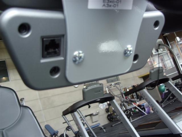
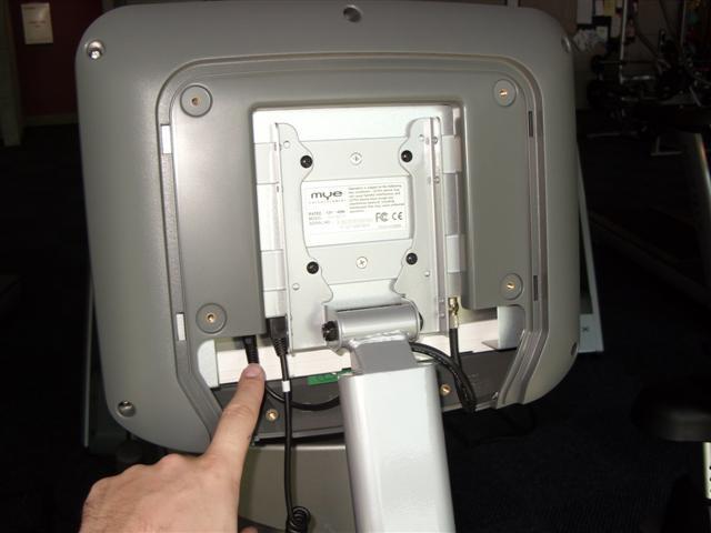
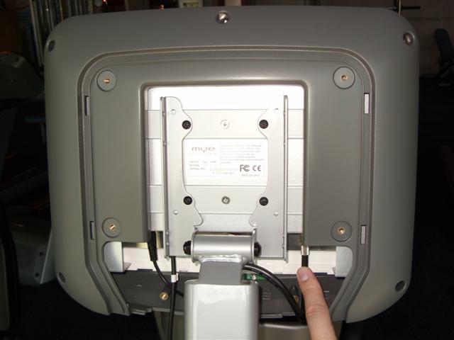
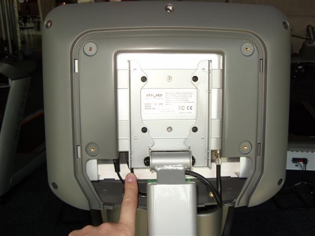
12 Chapter 4: CONSOLE overlay AND workout DESCRIPTION 4.2 CONSOLE DESCRIPTION - BACK Matrix is the leader in entertainment availability. On the back of the console are two RJ45 receptacles. They are marked CSAFE and ENTERTAINMENT. These ports allow the Ascent Trainer to be connected to a fitness entertainment system and / or a fitness network such as Fitlinxx. The ENTERTAINMENT port is compatible with entertainment protocol such as CardioVision or Broadcast Vision. 8
13 chapter 4: console overlay and workout description 4.3 workout setup steps - MANUAL 4.4 workout setup steps - level based GO - Press to immediately begin a workout. Workout, resistance level, incline level, and time will automatically go to default settings. Quick Start will not prompt user for age, weight, or level settings. 1) Start pedaling and press the QUICK START key to begin your workout. 2) The display will read Starting 3, Starting 2, Starting 1 and then the program will begin. MANUAL - Manual allows the user to input more information while defining their own workout. Calorie expenditure will be more accurate when inputting information in Manual than Go. 1) Start pedaling and press the MANUAL key. 2) Select Level by using the UP or DOWN arrow keys and press SELECT. 3) Select Time by using the UP or DOWN arrow keys and press SELECT. 4) Select Weight by using the UP or DOWN arrow keys and press SELECT. 5) The display will read Starting 3, Starting 2, Starting 1 and then the program will begin. RANDOM - There are 20 workout profiles in the Random Mode. The profile will change each time the RANDOM key is pressed. 1) Start pedaling and press the RANDOM key. 2) Select Level by using the UP or DOWN arrow keys and press SELECT. 3) Select Time by using the UP or DOWN arrow keys and press SELECT. 4) Select Weight by using the UP or DOWN arrow keys and press SELECT. 5) The display will read Starting 3, Starting 2, Starting 1 and then the program will begin. ROLLING / INTERVALS - The Rolling and Interval programs are level based programs that automatically adjust the resistance level and elevation level to simulate real terrain. 1) Start pedaling and press the ROLLING or INTERVALS key. 2) Select Level by using the UP or DOWN arrow keys and press SELECT. 3) Select Time by using the UP or DOWN arrow keys and press SELECT. 4) Select Weight by using the UP or DOWN arrow keys and press SELECT. 5) The display will read Starting 3, Starting 2, Starting 1 and then the program will begin. FAT BURN - Fat burn is a level based program that is designed to help users burn fat through various resistance level changes. 1) Start pedaling and press the FAT BURN key. 2) Select Level by using the UP or DOWN arrow keys and press SELECT. 3) Select Time by using the UP or DOWN arrow keys and press SELECT. 4) Select Weight by using the UP or DOWN arrow keys and press SELECT. 5) The display will read Starting 3, Starting 2, Starting 1 and then the program will begin. 9
14 Chapter 4: CONSOLE overlay AND workout DESCRIPTION 4.5 workout setup steps - fitness test FITNESS TEST -The Cooper Fitness Test measures cardiovascular fitness and proves an estimated sub-maximal VO2 result. It is based on power output according to ACSM standards and was developed by the Cooper Institute ( User RPMs must remain between RPM during the test. The test will end when the user can no longer maintain this speed. Use of a heart rate strap is optional but provides more data. The test starts at a low intensity level and gradually increases in intensity (difficulty) every 2 minutes. As it increases, the user must maintain RPM to advance to the next level. The test could take upwards of 30+ minutes for very fit individuals. Once the test ends a recovery period (cool down) will begin and the user's results are calculated and displayed. Results are based on the number of stages completed. 1) Start pedaling and press the FITNESS TEST key. 2) Select Age by using the UP or DOWN LEVEL keys and press SELECT. 3) Select Gender by using the UP or DOWN LEVEL keys and press SELECT. 4) Select Weight by using the UP or DOWN LEVEL keys and press SELECT. 5) The display will read Starting 3, Starting 2, Starting 1, and then the program will begin. 6) Once the workout is complete, the display will read the results of the Fitness Test. Percentile values for maximal Aerobic Power Age Percentile Men Women

15 Chapter 4: CONSOLE overlay AND workout DESCRIPTION 4.6 workout setup steps - heart rate 4.7 workout setup steps - watts TARGET HEART RATE - The Matrix Ascent Trainer comes with standard digital contact heart rate sensors and are POLAR telemetry compatible. Locate the metal sensors on the handlebars of the Ascent Trainer. Notice that there are two separate pieces of metal on each grip. You must be making contact with both pieces of each grip to get an accurate heart rate reading. You can grab these sensors in any program to view your current heart rate. The heart rate readout is located in the lower left hand corner and is labeled HEART RATE. 1) Start pedaling and press the TARGET HR key. 2) Select Age by using the UP or DOWN arrow keys and press SELECT. 3) Select Percent by using the UP or DOWN arrow keys and press SELECT. 4) Select Time by using the UP or DOWN arrow keys and press SELECT. 5) Select Weight by using the UP or DOWN arrow keys and press SELECT. 6) The display will read Starting 3, Starting 2, Starting 1 and then the program will begin. CONSTANT WATTS - Constant Watts is a unique program that allows you to vary your cadence or RPM and the Ascent Trainer's resistance level will adjust accordingly to your selected goal. The quicker you pedal, the less resistance for the goal selected. 1) Start pedaling and press the CONSTANT WATTS key. 2) Select Watts by using the UP or DOWN arrow keys and press SELECT. 3) Select Time by using the UP or DOWN arrow keys and press SELECT. 4) Select Weight by using the UP or DOWN arrow keys and press SELECT. 5) The display will read Starting 3, Starting 2, Starting 1 and then the program will begin. Heart Rate Protocols: * HR is within 10 BPM (beats per minute) of target, upper LED display will show a heart. * HR is within 10 BPM of target, resistance level will increase or decrease every 10 seconds. * HR is greater than 14 BPM of target, resistance level will drop to 30%. * HR is greater than 10 BPM of target, display will read: "WARNING HR ABOVE TARGET". * HR is greater than 20 BPM of target, program will immediately end. 11
16 Chapter 5: MANAGER MODE 5.1 USING manager mode The Manager's Custom Mode allows the club owner to customize the Ascent Trainer for the club. 1) To enter Manager Mode, press and hold down the UP and DOWN LEVEL keys. Continue to hold down these two keys until the display reads Manager. 2) To scroll through the list of options in Manager Mode, use the UP and DOWN LEVEL keys. Each of the custom settings will show on the display. 3) To select a custom setting, press the SELECT key when the desired setting is shown. 4) To change the value of the setting, use the UP and DOWN LEVEL keys. 5) To confirm and save the value of the setting, press the START key. Setting saved will appear on the display. 6) To exit the setting without saving, press and hold the SELECT key. 7) Press the START key twice to return to normal operation. 12
17 chapter 5: MANAGER MODE 5.2 MANAGER MODE OVERVIEW CODE CUSTOM SETTING DEFAULT MINIMUM MAXIMUM Description P0 Maximum Program Time 95 min 10 min 95 min Sets the total run time of any program. P1 Default Workout Time 20 min 10 min Maximum Time Setting Workout time when GO is pressed or when no time is selected during program set up. P2 Default Resistance Level Starting resistance when GO is pressed or when no resistance is selected during program set up. P3 Default User Weight 150 lbs / 75 kg 80 lbs / 36 kg 400 lbs / 181 kg Weight used for program calorie expenditure calculations. P4 Speed Units MILE KILOMETER MILE Display value in miles or kilometers. P5 Machine Type SWING RAMP SWING The Ascent Trainer console should always be set as SWING. P6 Console Beep On / Off ON OFF ON Confirmation beeps when keys are pressed can be turned on or off. P7 Accumulated Distance N/A 0 65,000 Miles P8 Accumulated Time N/A 0 65,000 hours Total distance for all programs. Total time for all programs displayed in hours. P9 Display Language ENGLISH N/A N/A Select between English, French, Spanish, Italian, Dutch, and German. P10 Software Version N/A N/A N/A Current version of console software. P11 Incline Calibration OFF OFF ON Default display is OFF. Selecting ON will automatically calibrate the incline motors to factory settings. Use this feature when actual elevation does not match console display. P12 Incline Reset ON OFF ON This is a software feature that resets machine elevation to 0 degrees after 30 seconds of user inactivity. During incline reset, movement can be stopped by pressing any console key. The display will scroll "HOLD SELECT TO RESUME." To resume reset to 0 degrees, hold the SELECT key for 3 seconds. P13 Default Incline Level 10 Starting incline level at each program starts except Fit Test. Factory setting is 10%. In Fit Test, elevation is set to 0%. P14 Error Code N/A N/A N/A Console will record up to 3 errors. Error codes are stored permanently until reset by a technician. To reset error codes, hold MANUAL and RANDOM keys for 3 seconds. P15 LCB Version N/A N/A N/A Display will show LCB.VER XX YYY. XX is machine type, YYY is the software version number. 13
18 Chapter 6: Engineering / service MODE 6.1 engineering / service mode To enter Engineering or Service Mode, hold the UP and DOWN LEVEL keys for 3 seconds until Manager Mode appears on the middle LED display. Press the UP or DOWN LEVEL key to scroll between the different Engineering and Service Modes. This mode is for factory settings only. ENGINEERING MODE SERVICE MODE SERVICE 1: Display Test. SERVICE 2: RPM Reading. SERVICE 3: Accumulated Distance and Time. SERVICE 4: Heart Rate Test. 14
19 Chapter 7: TROUBLESHOOTING 7.1 Electrical Diagrams 15
20 Chapter 7: TROUBLESHOOTING 7.1 electrical diagrams Wiring Diagram Instructions 16
21 Chapter 7: TROUBLESHOOTING 7.1 electrical diagrams P05 - Console Cable P04 Pulse Sensor Wire 17
22 chapter 7: troubleshooting 7.1 electrical diagrams P02 Elevation Wire P14 ECB Load Wire 18
23 Chapter 7: TROUBLESHOOTING 7.2 LCB ERROR INDICATORS LCB Power indicator light DN1 - Indicates if the upper console is commanding Elevation 1 DOWN. DN2 - Indicates if the upper console is commanding Elevation 2 DOWN. UP1 - Indicates if the upper console is commanding Elevation 1 UP. UP2 - Indicates if the upper console is commanding Elevation 2 UP. RPM - Rotation rate for speed. BRK - Resistance indicator light. RL - Relay indicator light. STATUS - Digital communication state indicator light. OL1 - Elevation 1 error indicator light. OL2 - Elevation 2 error indicator light. 19
 The keypad connection ribbon cable has not been plugged in correctly.")
. c. Inspect the keypad ribbon cable connection at the UCB (Figure B). d.")
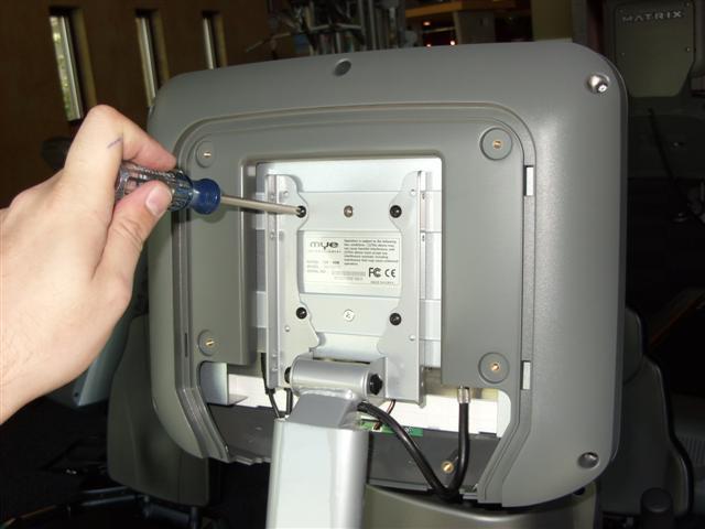
24 chapter 7: troubleshooting 7.3 troubleshooting - Keypad issues possible causes: all or some of the function keys do not respond 1) The keypad connection ribbon cable has not been plugged in correctly. 2) The keypad is damaged. 3) The console is damaged. SOLUTION: 1) Check the connections of the keypad at the Upper Control Board. a. Remove the console from the console mast. b. Remove the 6 screws holding the back of the console to the front (Figure A). c. Inspect the keypad ribbon cable connection at the UCB (Figure B). d. Even if the keypad ribbon cable appears to be connected correctly, unplug and re-seat the cable, then retest. 2) Replace the affected keypad. 3) Replace the console. Figure A Figure B 20
 The ECB is damaged. 4) The Lower Control Board is damaged. High or no resistance SOLUTION: 1) Check the console cable connections at the UCB.")
25 Chapter 7: TROUBLESHOOTING 7.4 TROUBLESHOOTING - RESISTANCE ISSUES possible causes: 1) The console cable is damaged or not properly plugged in. 2) The Upper Control Board is damaged. 3) The ECB is damaged. 4) The Lower Control Board is damaged. High or no resistance SOLUTION: 1) Check the console cable connections at the UCB. 2) Remove the front covers and check the console cable connection at the LCB. Also confirm that LED RBK on the LCB is lit. If it is not, replace the LCB. 3) Check if the ECB is conducting power: a. Insert the probes from a multi-meter into the black and red wires on the ECB wire harness connector (Figure A). b. The output voltage from the ECB should be ohms. 4) If the ECB reading is not between 8 and 15 ohms, replace the ECB. 5) If the ECB reading is between 8 and 15 ohms, replace the LCB. 6) If both the ECB and LCB have been replaced and the issue is still present, replace the console. Figure A 21
26 Chapter 7: TROUBLESHOOTING 7.5 TROUBLESHOOTING PEDALS SLIPPING Possible causes: pedals slipping 1) The belt tension is not enough. 2) The one way bearing is damaged. SOLUTION: 1) Remove the covers and check the belt tension. a. The drive belt should be tightened to 180 ft / lbs. b. The ECB belt should be tightened to 120 ft / lbs. 2) If the belts are tensioned correctly, the one way bearing is damaged, replace the drive assembly. 7.6 Troubleshooting - Noise Issues Possible causes: 1) The pedal is on the pedal arm too loosely. 2) The drive axle is worn out. 3) The belt tension is not enough, or the belts are too dirty. Knocking or creaking noise SOLUTION: 1) Retighten the pedal onto the pedal arm. 2) Replace the drive axle as needed. 3) Remove the covers and check the belt tension. a. The drive belt should be tightened to 180 ft / lbs. b. The ECB belt should be tightened to 120 ft / lbs. 4) Clean the belts. If they are worn or will not clean, replace the belts. 22
 Poor connection to the terminals on the console. 3) The console is damaged. 4) The generator is damaged.")
27 CHAPTER 7: TROUBLESHOOTING 7.7 troubleshooting - CONSOLE issues POSSible causes: no display on the console or the console is dim 1) The console cable is damaged or not properly connected. 2) Poor connection to the terminals on the console. 3) The console is damaged. 4) The generator is damaged. SOLUTION: 1) Unplug the console cable at the console and use a multi-meter to check if the voltage between pin 1 (Vcc) and pin 8 (Ground) of the console cable is greater than 12 Volts DC. If it is, replace the console. 2) Remove the front covers and check the console cable connection at the LCB. Also confirm that LED +12 on the LCB is lit. If it is not, replace the LCB. 3) Check if the generator is outputting variable power: a. Insert the probes from a multi-meter into the black and red wires on. the generator wire harness connector (Figure A). b. When pedaling, the output voltage from the generator should vary. depending on the RPM. The generator should output 120 VAC at. 94 RPM. c. If the generator is not outputting variable power, replace the... ECB. d. If the ECB is outputting variable power, replace the lower control... board. Figure A 23
28 Chapter 7: TROUBLESHOOTING 7.8 troubleshooting - Heart Rate Issues heart rate function does not work or is reading incorrectly possible causes: 1) The chest strap being used is not making good contact with the user's chest. 2) The chest strap is at a low battery status. 3) The chest strap is damaged. 4) The HR grips are damaged. 5) The HR board is damaged. 6) The Upper Control Board is damaged. SOLUTION: 1) Re-center the chest strap below the user's pectoral muscle (Figure A) and check again. 2) Replace the battery in the chest strap. 3) Replace the chest strap. 4) If there is no HR present, replace the HR grips. 5) If there is a HR present but it is much higher than normal, replace the HR board. 6) If replacing the HR grips and board does not resolve the issues, replace the console. figure a 24
 The unit has incorrect software in the Lower")
 Scroll to P10 Software Version using the LEVEL keys and press SELECT. a. Confirm the LCB software version is S004 or higher, if it S003 or lower, replace the LCB.")
29 Chapter 7: TROUBLESHOOTING 7.9 Troubleshooting - Motor Overload, over current, or Synchronization Errors Motor Overload, Over Current, or Synchronization Error POSSIBLE CAUSES: 1) The unit has incorrect software in the Lower Control Board. 2) The incline motor(s) are damaged. SOLUTION: 1) Press and hold both LEVEL keys until Manager appears on the display. 2) Scroll to P10 Software Version using the LEVEL keys and press SELECT. a. Confirm the LCB software version is S004 or higher, if it S003 or lower, replace the LCB. 3) Open the left and right rear covers (Figures A & B). 4) Scroll to P11 Calibration using the LEVEL keys and press SELECT. a. Check to see if one or both of the incline motors are slow or not moving. If so, replace the affected incline motor. Figure A Figure B 25
 Press and hold both LEVEL keys until Manager appears on the display. 2) Scroll to P5 Machine using the LEVEL keys and press SELECT. a. This should be set for SWING at all times.")
 Open the right side front disk and check the incline motor connections at the LCB (Figure A).")
30 Chapter 7: TROUBLESHOOTING 7.10 troubleshooting - motor unplugged error Possible Cause: Motor Unplugged Error 1) Console is not receiving a signal from the incline motors. SOLUTION: 1) Press and hold both LEVEL keys until Manager appears on the display. 2) Scroll to P5 Machine using the LEVEL keys and press SELECT. a. This should be set for SWING at all times. If it is set for RAMP, change using the LEVEL keys, then press START to save. Test the unit for function. 3) Open the right side front disk and check the incline motor connections at the LCB (Figure A). 4) Open the right and left rear covers and check the connection between the incline motor wire and the incline motor extended wire (Figure B). 5) Scroll to P11 Calibration using the LEVEL keys and press SELECT. a. Check to see if one or both of the incline motors are slow or not moving. If so, replace the affected incline motor. Figure A Figure B 26
 Remove the link arm and pedal arm plastic caps (Figures A")
 Detach the link arm from the crank bearing assembly (Figure D).")
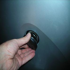
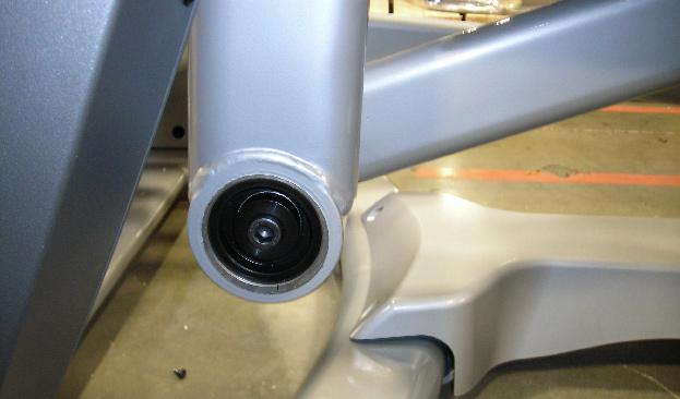
 Press the center cap and turn it counter clockwise to remove (Figure F).")
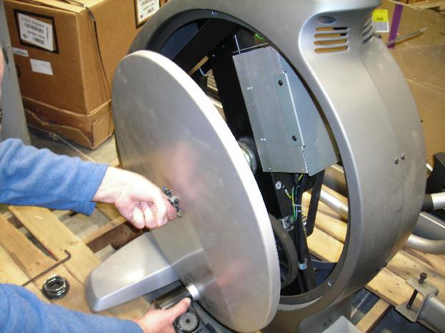
. 7) Thread the Matrix disk removal tool into the center hub (Figure H).")
. Repeat if necessary for the opposite side disk.")
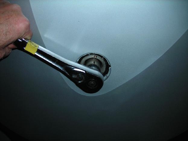
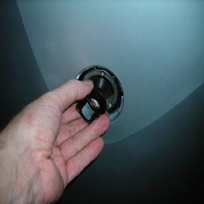
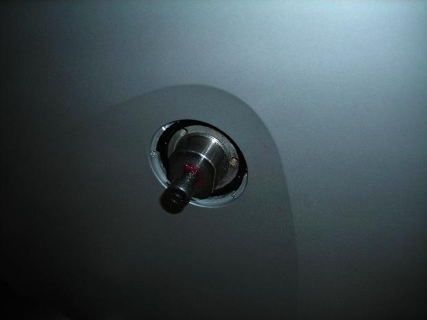
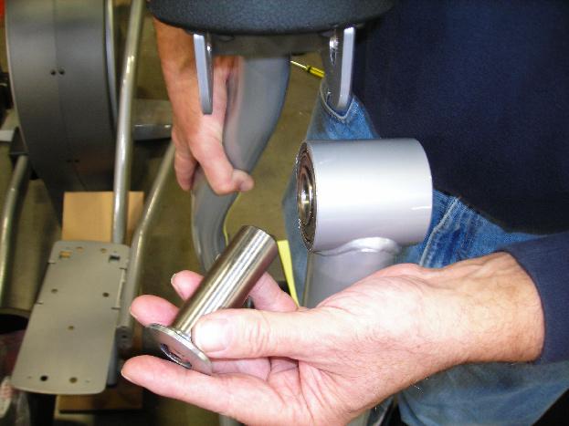
31 Chapter 8: Part Replacement Guide 8.1 FRONT DISK REMOVAL 1) Remove the link arm and pedal arm plastic caps (Figures A and B). 2) Detach the dual-action handlebar at the pedal arm (Figure C). 3) Detach the link arm from the crank bearing assembly (Figure D). 4) Rest the link arm padded surface on the front stabilizer (Figure E). 5) Press the center cap and turn it counter clockwise to remove (Figure F). 6) Remove the 24mm locking nut and washer by turning them counter clockwise (Figure G). 7) Thread the Matrix disk removal tool into the center hub (Figure H). 8) Turn the center bolt of the removal tool clockwise until the main disk can be removed (Figures I and J). Repeat if necessary for the opposite side disk. 9) When reinstalling the 24mm nut, it should be tightened to 196 N-m Torque. figure a figure b figure c figure d figure e 27


32 Chapter 8: Part Replacement Guide 8.1 FRONT DISK REMOVAL CONTINUED figure f figure g figure h figure i figure j 28
 Remove the 6 screws that hold the front shrouds in place on each side (Figure A).")
33 Chapter 8: Part Replacement Guide 8.2 FRONT SHROUD REMOVAL 1) Remove the front disks as outlined in Section ) Remove the 6 screws that hold the front shrouds in place on each side (Figure A). 3) Remove the front shrouds for frame access (Figure B). figure a figure b 29
 Turn off the power and disconnect the cord from the machine.")
 Remove the 2 screws holding the cover on the lower control board to allow wiring access.")
 Remove the 2 screws holding the LCB to the frame and remove the LCB. (Figure C).")
34 Chapter 8: Part Replacement Guide 8.3 lower control board replacement 1) Turn off the power and disconnect the cord from the machine. 2) Remove both front disks from the machine as outlined in Section ) Remove the 2 screws holding the cover on the lower control board to allow wiring access. (Figure A). 4) Disconnect all wires from the LCB (7 connections) (Figure B). 5) Remove the 2 screws holding the LCB to the frame and remove the LCB. (Figure C). 6) Reverse Steps 1-5 to install a new LCB. 7) Test the Ascent Trainer for function as outlined in Section figure a figure b figure c 30
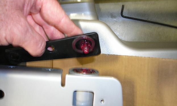
 Unplug the ECB (under mast connection point) from the wire harness (Figures A & B). 5) Loosen the 11mm nut on the tension loop bolt (Figure C).")
 Remove the old ECB and install the new ECB from the user s left side of the frame. (Figure F). 9) Install the 6 frame mounting bolts loosely & attach the belt. (Figure G).")
 Reconnect the ECB wires, reassemble the front disks and shrouds. 13) Test the Ascent Trainer as outlined in Section 8.20.. figure a figure b figure c figure d 31")
35 Chapter 8: Part Replacement Guide 8.4 ECB REPLACEMENT 1) Turn off power and disconnect the cord from the machine. 2) Remove the front disks as outlined in Section ) Remove the front shrouds as outlined in Section ) Unplug the ECB (under mast connection point) from the wire harness (Figures A & B). 5) Loosen the 11mm nut on the tension loop bolt (Figure C). 6) Remove the tension loop bolt from the ECB bracket. (Figure D). 7) Remove the 6 bolts holding the ECB to the frame & remove the belt once loosened (Figure E). 8) Remove the old ECB and install the new ECB from the user s left side of the frame. (Figure F). 9) Install the 6 frame mounting bolts loosely & attach the belt. (Figure G). 10) Attach the tension loop bolt to the ECB bracket and tension the belt to 120 lbs using an 11mm nut (Figure H). 11) Tighten the 6 frame mounting bolts to 12 N-m torque. 12) Reconnect the ECB wires, reassemble the front disks and shrouds. 13) Test the Ascent Trainer as outlined in Section figure a figure b figure c figure d 31

36 Chapter 8: Part Replacement Guide 8.4 ECB REMOVAL AND INSTALLATION CONTINUED figure e figure f figure g figure h 32
 Remove the 2 screws holding the")
 Remove the cup holder (Figure B).")
37 Chapter 8: Part Replacement Guide 8.5 cup holder replacement 1) Remove the 2 screws holding the cup holder to the console mast (Figure A). 2) Remove the cup holder (Figure B). 3) Reverse Steps 1-2 to install a new cup holder. Figure A Figure B 33
 Turn off the power and disconnect the cord from the machine.")
 To remove the drive belt, loosen the belt tension bolt on the left side of the tension pulley and rotate the pulley")
 To remove the ECB belt, loosen the 6 bolts holding the ECB to the frame (Figure D).")
 Install the replacement belt(s) and reverse necessary steps to secure the assembly until the belt is tight.")
38 Chapter 8: Part Replacement Guide 8.6 BELTS REMOVAL AND INSTALLATION 1) Turn off the power and disconnect the cord from the machine. 2) Remove the front disks from the machine as outlined in Section ) To remove the drive belt, loosen the belt tension bolt on the left side of the tension pulley and rotate the pulley counter-clockwise until there is enough slack in the belt to remove it (Figures B &C). 4) To remove the ECB belt, loosen the 6 bolts holding the ECB to the frame (Figure D). 5) Loosen the 11 mm nut on the tension loop bolt until there is enough slack in the belt to remove it (Figure E). 6) Install the replacement belt(s) and reverse necessary steps to secure the assembly until the belt is tight. Tighten the 6 ECB bolts to 12 N-m torque. Tighten the drive belt to 180 lbs. for a new belt, 150 lbs. for a used belt. Tighten the ECB belt to 120 lbs. 7) Test the Ascent Trainer for function as outlined in Section figure a figure b figure c figure d figure e 34
 Remove both front disks from the machine as outlined in Section 9.1.")
 Release any bent tabs on the lock washer around the nut. Remove the 75mm nut from the assembly being serviced (Figure C).")
 Remove the bearing assembly, and clean any debris from the frame (Figure E).")
39 chapter 8: part replacement guide 8.7 PULLEY AXLE SET REPLACEMENT 1) Turn off the power and disconnect the cord from the machine. 2) Remove both front disks from the machine as outlined in Section ) Loosen the belt tension bolt on the right side until there is enough slack to remove the drive belt and tensioner (Figures A & B). 4) Release any bent tabs on the lock washer around the nut. Remove the 75mm nut from the assembly being serviced (Figure C). Shown with special tool available from Matrix Fitness. 5) Remove the tapered split ring that is held in place by the nut (Figure D). 6) Remove the bearing assembly, and clean any debris from the frame (Figure E). 7) Reverse steps 1-6 to install a new pulley axle set, making sure to tighten the 75mm nut to 100 N-m torque and re-bend the lock washer tabs to secure the nut. Reinstall the belts as outlined in Sections 8.5 and ) Test the Ascent Trainer for function as outlined in Section figure a figure b figure c figure d figure e 35
 Release any bent tabs on the lock washer around the nut. Remove the 75mm nut from the assembly being serviced (Figure A). Shown with special tool available from Matrix Fitness.")
40 Chapter 8: Part Replacement Guide 8.8 DRIVE AXLE SET REPLACEMENT 1) Turn off the power and disconnect the cord from the machine. 2) Remove the front disks from the machine as outlined in Section ) Remove both belts as outlined in Sections 8.5 & ) Release any bent tabs on the lock washer around the nut. Remove the 75mm nut from the assembly being serviced (Figure A). Shown with special tool available from Matrix Fitness. 5) Remove the tapered split ring that is held in place by the nut (Figure B). 6) Remove the drive axle set and clean any debris from the frame (Figure C). 7) Reverse steps 1-6 to install a new drive axle set, making sure to tighten the 75mm nut to 100 N-m torque and re-bend the lock washer tabs to secure the nut. Reinstall the belts as outlined in Sections 8.5 and ) Test the Ascent Trainer for function as outlined in Section figure a figure b figure c 36
 Remove the 4 screws that hold the console to the top of the console mast (Figure A).")
 Carefully push the wires into the console and mast until they are clear of the console/mast connection and attach the console to the mast using the 4")
41 Chapter 8: Part Replacement Guide 8.9 CONSOLE REPLACEMENT 1) Turn off the power and disconnect the cord from the machine. 2) Remove the 4 screws that hold the console to the top of the console mast (Figure A). 3) Disconnect the data cable, heart rate, and ground wires and remove the console (Figure B). 4) Reconnect the wire connections to the new console. 5) Carefully push the wires into the console and mast until they are clear of the console/mast connection and attach the console to the mast using the 4 screws removed in Step 2. 6) Test the Ascent Trainer for function as outlined in Section figure a figure b 37
 Remove the console from the machine as outlined in section 8.9. 3) Remove the 6 screws holding the console together and remove the back of the console (Figure A).")
 Remove excess adhesive from the plastic.")
 Remove the backing from the new keypad (Figure E).")
 Attach the keypad ribbon cable to the console control board by pressing carefully into place (Figure F). 9) Remove the backing from the new overlay(s) (Figure G).")
42 Chapter 8: Part Replacement Guide 8.10 CONSOLE OVERLAYS & KEYPADS REPLACEMENT 1) Turn off the power and disconnect the cord from the machine. 2) Remove the console from the machine as outlined in section ) Remove the 6 screws holding the console together and remove the back of the console (Figure A). 4) Using a razor blade, carefully peel up one corner of the overlay (Figure B) and then remove the entire overlay (Figure C). NOTE: If just replacing overlays, only complete Steps 1-4 and ) Remove excess adhesive from the plastic. 6) Remove the faulty keypad(s) by disconnecting the appropriate ribbon cable(s) from the circuit board, and remove it from the console (Figure D). 7) Remove the backing from the new keypad (Figure E). To install a new keypad, slide the ribbon cable through the console and align the keypad with the console house and press it into place. 8) Attach the keypad ribbon cable to the console control board by pressing carefully into place (Figure F). 9) Remove the backing from the new overlay(s) (Figure G). To install a new overlay, align the overlay with the console housing and press into place being careful to avoid air bubbles and misalignment. 10) Reattach the back of the console using the 6 screws removed in Step 3 and re-install the console onto the mast of the machine (Figure H). 11) Test the Ascent Trainer for function as Section figure a figure b figure c figure d 38


43 Chapter 8: Part Replacement Guide 8.10 CONSOLE KEYPAD & OVERLAY REPLACEMENT - CONTINUED figure e figure f figure g figure h 39
 Turn off the power and disconnect the cord from the machine.")
 Remove the 4 bolts that hold the handlebar to the console mast being careful to support the handlebar")
 Carefully remove the wires from inside the console mast until the connectors on the ends come free and")
 To install a new handlebar assembly, connect the new handlebar and carefully push the heart rate wires")
44 Chapter 8: Part Replacement Guide 8.11 handlebar assembly replacement 1) Turn off the power and disconnect the cord from the machine. 2) Remove the two screws holding the plastic handlebar cover in place and remove the cover (Figure A). 3) Remove the 4 bolts that hold the handlebar to the console mast being careful to support the handlebar (Figures B and C). 4) Carefully remove the wires from inside the console mast until the connectors on the ends come free and disconnect (Figure D). 5) To install a new handlebar assembly, connect the new handlebar and carefully push the heart rate wires into the console mast. 6) Attach the new handlebar assembly to the console mast using the 4 screws removed in Step 3. 7) Reattach the cover over the handlebar assembly. 8) Test the Ascent Trainer for function as outlined in Section figure a figure b figure c figure d 40
 Remove the 3 screws on the outer shroud (1 at the rear of the machine and 2 at the front)")
 4) Repeat the same steps for the other side of the machine. 5) Reverse steps 1-4 to install new shrouds.")
45 Chapter 8: Part Replacement Guide 8.12 REAR SHROUD REPLACEMENT 1) Remove the 3 screws on the outer shroud (1 at the rear of the machine and 2 at the front) (Figure A). 2) Remove the 6 screws on the inner shroud (Figure B). 3) Remove the shrouds from the machine. (Figure C) 4) Repeat the same steps for the other side of the machine. 5) Reverse steps 1-4 to install new shrouds. 6) Test the Ascent Trainer for function as outlined in Section figure a figure b figure c 41
46 Chapter 8: Part Replacement Guide 8.13 INCLINE MOTOR REPLACEMENT 1) Turn off the power and disconnect the cord from the machine. 2) Remove the rear shrouds as outlined in Section ) Disconnect the incline motor ground wire from frame. (Figure A). 4) Carefully remove the two 8mm bolts that hold the swing arm to the motor assembly (Figure B). Make sure to secure the swing arm as once the bolts are removed it will fall (Figure C) 5) Move the swing arm up to rest against the frame so it is clear of the motor. 6) Remove the motor by disassembling the pivot bolt (Figure D) and disconnecting the wire connection (Figure E). 7) Prepare the new motor for installation, the new motor will have the nut placed at the end of the screw shaft DO NOT move the nut (Figure F). 8) Install the new motor using the plastic washers (Figure G). 9) Reverse Step 6 to secure the new incline motor in place, and then reconnect the ground wire from step 2. NOTE: Do not overtighten the pivot bolt the incline motor must be able to swivel. 10) Reconnect the power cord and turn the machine on. Enter Manager Mode by pressing and holding the UP and DOWN LEVEL keys at the same time. Manager will appear on the display, press SELECT. Using the UP ELEVATION key, toggle to P11 (Motor Calibration) and press SELECT. After the calibration sequence is complete the motors will stop turning. Turn the machine off and remove the power cord again. 11) Set the nut on the Acme screw to a distance of 67mm from the base of the motor casing to the furthest end of the nut (Figure H). 12) Reattach the swing arm to the nut with 8mm bolts by reversing Step 4. 13) Reinstall the rear shrouds. 14) Test the Ascent Trainer for function as outlined in Section figure a figure b 42


47 Chapter 8: Part Replacement Guide 8.13 INCLINE MOTOR REPLACEMENT - CONTINUED figure c figure d figure e figure f figure g figure h 43
 Remove the plastic cover where the dual action handlebar meets the pedal arm (Figure A).")
 Remove the two bolts holding the dual action handlebar to the console mast pivot (Figure C). 4) Remove the pivot cap and handlebar (Figure D).")
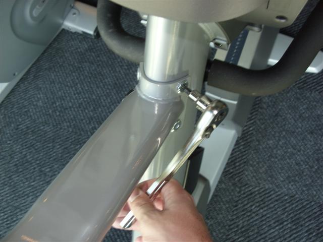
48 chapter 8: part replacement guide 8.14 dual action handlebar replacement 1) Remove the plastic cover where the dual action handlebar meets the pedal arm (Figure A). 2) Remove the bolt and bushings where the dual action handlebar and the pedal arm meet (Figure B). 3) Remove the two bolts holding the dual action handlebar to the console mast pivot (Figure C). 4) Remove the pivot cap and handlebar (Figure D). 5) Reverse steps 1-4 to install a new dual action handlebar. 6) Test the Ascent Trainer for function as outlined in Section figure a figure b figure c figure d 44
 Remove the 4 Phillips")
.")
 Remove the rubber grip (Figure C).")
.")
49 Chapter 8: Part Replacement Guide 8.15 FOOT PEDALS REPLACEMENT 1) Remove the 4 Phillips screws that hold the plastic foot pedal to the foot plate (Figure A). 2) Remove the plastic foot pedal (Figure B). 3) Remove the rubber grip (Figure C). 4) Clean the foot plate to remove any rubber or debris (Figure D). 5) Reverse Steps 1-4 to install a new foot pedal. 6) Test the Ascent Trainer as outlined in Section figure a figure b figure c figure d 45
 Remove the bolt and bushings where the dual action handlebar and the pedal arm meet (Figure B). 3) Remove the pedal as outlined in Section 8.15.")
 Slide the pedal arm shaft out of the link arm housing noting the order of the washers on the pedal arm shaft (Figure D). 6) Reverse Steps 1-5 to install a new pedal arm.")
50 Chapter 8: Part Replacement Guide 8.16 PEDAL ARM REPLACEMENT 1) Remove the plastic cover where the dual action handlebar meets the pedal arm (Figure A). 2) Remove the bolt and bushings where the dual action handlebar and the pedal arm meet (Figure B). 3) Remove the pedal as outlined in Section ) Remove the 3 bolts that hold on the mounting plate at the link arm / pedal arm joint (Figure C). Note the plastic washer that mounts at the end of the shaft. 5) Slide the pedal arm shaft out of the link arm housing noting the order of the washers on the pedal arm shaft (Figure D). 6) Reverse Steps 1-5 to install a new pedal arm. 7) Test the Ascent Trainer for function as outlined in Section figure a figure b figure c figure d 46
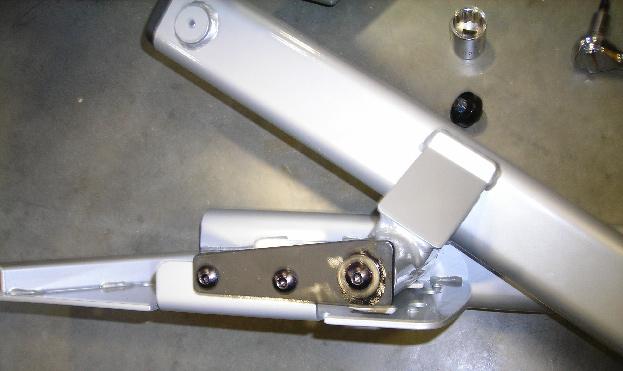
 Disconnect the link arm from the crank assembly (Figure B). 3) Disconnect the pedal and link arm from the rear of the machine by separating the joint between the swing arm and the link arm.")
51 chapter 8 : part replacement guide 8.17 link arm replacement 1) Remove the plastic cover at the joint of the link arm and the crank assembly (Figure A). 2) Disconnect the link arm from the crank assembly (Figure B). 3) Disconnect the pedal and link arm from the rear of the machine by separating the joint between the swing arm and the link arm. Remove the plastic cap from the swing arm bushing to reveal the bolt and washer that hold the joint together. Remove the bolt (tighten to 28 N-m torque during reassembly) and separate the link and pedal arms from the swing arm (Figures C & D). 4) Remove the 3 bolts that hold on the mounting plate at the link arm / pedal arm joint (Figure E). Note the plastic washer that mounts at the end of the shaft. 5) Slide the pedal arm shaft out of the link arm housing noting the arrangement of the washers on the pedal arm shaft. (Figure F). 6) Reverse Steps 1-5 to install a new link arm. 7) Test the Ascent Trainer for function as outlined in Section figure a figure b 47

52 Chapter 8: Part Replacement Guide 8.17 link arm replacement - continued 48
 Remove the bolt that holds the swing arm to the pedal and link arms (Figure B).")
 Loosen one of the bolts on either side of the upper pivot joint (Figure E).")
 Transfer the rubber arm pad and plastic parts to the new swing arm. (Figure H). 7) Reverse Steps 1-6 to install the new swing arm.")
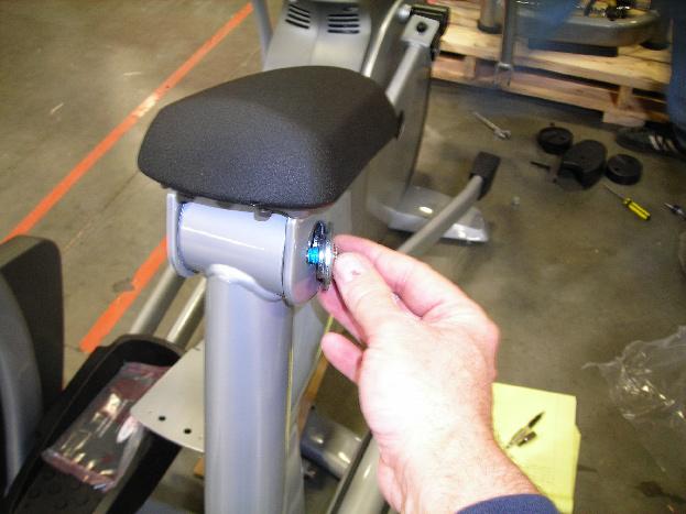
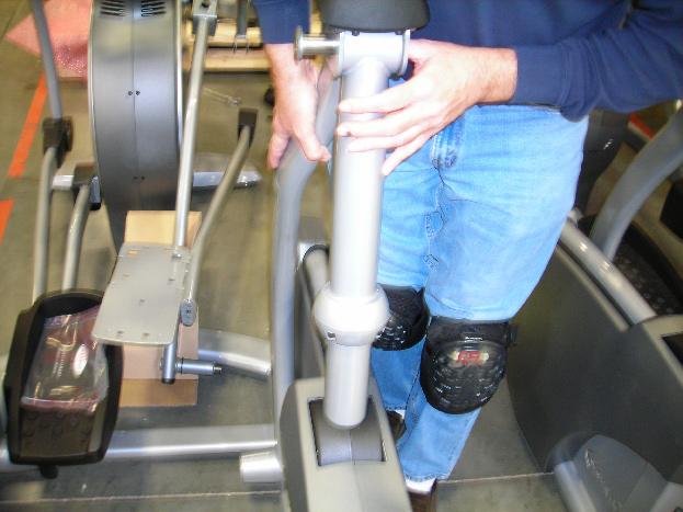
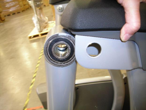
53 Chapter 8: Part Replacement Guide 8.18 SWING ARM REPLACEMENT 1) Remove the black plastic cover on the lower swing arm joint (Figure A). 2) Remove the bolt that holds the swing arm to the pedal and link arms (Figure B). 3) Carefully tap the crank arm inward until it can be pulled free of the bearing housing (Figure C & D). 4) Loosen one of the bolts on either side of the upper pivot joint (Figure E). 5) Holding onto the swing arm, push / pull the pivot shaft out of the bearing housing (Figures F and G). 6) Transfer the rubber arm pad and plastic parts to the new swing arm. (Figure H). 7) Reverse Steps 1-6 to install the new swing arm. NOTE: Be aware of the spacer between the bearings that the shaft passes through (Figure I). 8) Test the Ascent Trainer for function as outlined in Section figure a figure b figure c 49


54 Chapter 8: Part Replacement Guide 8.18 SWING ARM REPLACEMENT - CONTINUED figure d figure e figure f figure g figure h figure i 50
 Turn off the power and disconnect the cord from")
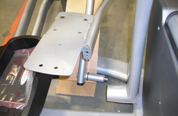
 Remove the bolts holding the rear pivot arm to the incline motor (Figure A).")
 and carefully swing the upper arm assembly forward and out of the")
.")
 Reverse Steps 1-6 to install a new pivot arm assembly.")
55 Chapter 8: Part Replacement Guide 8.19 REAR PIVOT ARM REPLACEMENT 1) Turn off the power and disconnect the cord from the machine. 2) Remove the rear shrouds as outlined in Section ) Remove the bolts holding the rear pivot arm to the incline motor (Figure A). 4) Remove the 4 bolts that hold the upper pivot arm assembly to the lower pivot arm (Figure B) and carefully swing the upper arm assembly forward and out of the way. 5) Remove the pivot shaft bolt and taper washer from the pivot assembly (Figures C & D). 6) Remove the pivot shaft and rear pivot arm from the frame (Figure E). 7) Reverse Steps 1-6 to install a new pivot arm assembly. NOTE: Tighten the pivot shaft bolt to 40 N-m torque. 8) Test the Ascent Trainer for function as outlined in Section figure a figure b figure c figure d figure e 51
56 Chapter 8: Part Replacement Guide 8.20 TESTING THE ASCENT TRAINER Once the unit or replacement part is fully installed and assembled and properly placed on the floor, use the following instructions to test the machine: 1) Without hitting start or entering any exercise modes, stand on the machine and hold the handlebars while initiating movement to simulate exercising. While moving listen for any odd noises or squeaks. 2) After stopping movement, press the green START key and begin using the machine. 3) Grasp the hand grips to check for proper heart rate response. 4) Press the LEVEL UP and DOWN keys both on the hand grips and on the console to make sure resistance is fully functional. 5) Press the ELEVATION UP and DOWN keys (fully incline and decline the machine) to make sure the incline motor function is fully operational. (If "motor synchronization error comes up, enter the manager mode by pressing the LEVEL UP and DOWN keys at the same time for 3 seconds. Press the SELECT button to enter the manager mode menu and scroll through the screens by pressing either the ELEVATION or LEVEL UP or DOWN keys to P11 (calibrate) and press SELECT to calibrate the motors. Once the motors finish moving press the START key twice to exit manager mode. Press the START key again to start the machine and recheck the elevation using the ELEVATION UP or DOWN keys to verify that calibration worked. 6) If everything functions properly the machine will reset after 30 seconds and is ready for use. 52
57 chapter 9: ascent trainer specifications and assembly guide 9.1 Ascent trainer specifications console Display Type Display Feedback Programs Resistance Levels 25 Elevation Levels 20 One Button Quick Start CSafe Pause Time On the Fly Program Change Full Course Screen View Entertainment Technical data Resistance Technology Power Requirements Minimum Watts 15 LED Maximum Watts 600 Overall Dimensions (L x W x H) Maximum User Weight Unit Weight Shipping Weight Transport Wheel USER DATA Incline, Time, Speed, Distance, Calories, Watts, Level, HR, RPM Heart Rate, Constant Watts, Manual, Random, Interval, Fat Burn and Rolling Hills Yes Yes 30 Seconds Yes Yes FITCONNEXION Ready JID Hybrid ECB 120V Stride Length 21-24" Incline Range 30" Constant Rate of Acceleration Contact Heart Rate Sensors Telemetric Heart Rate Receiver Replaceable Foot Pedal Inserts Q-Factor 3.75" Handle Bar Design 80" x 34.5" x 72" / x 87.7 x cm 400 lbs / kg 390 lbs / kg 434 lbs / kg Yes Yes Yes Yes Yes Multi-position dual action and ergo bend stationary. 53
58 Chapter 9: Ascent trainer specifications and assembly guide 9.2 FASTENERS & ASSEMBLY TOOLS quantity part # sketch description Hardware bag 01 6 mm allen wrench 01 phillips screwdriver mm open wrench 04 Z01 hex socket head cap (M8 x 15L) Yellow 08 Z02 Hex socket head cap (M8 x 20L) Black 06 Z03 cross truss head (M5 x 10L) White 04 Z04 hex socket head cap (M8 x 65L) White 02 Z05 hex socket head cap (M8 x 55L) White 02 Z06 flat washer (8.2 x 16.0 x 1.0) White 02 Z07 nylon nut (m8 x 1.25L) White 04 Z08 Axle White 04 Z09 Hex Socket Head Cap (M8 x 25L) Yellow 02 B28 cross truss head (M5 x 8L) Included in console 54

59 Chapter 9: ascent trainer specifications and assembly guide 9.3 ASCENT TRAINER ASSEMBLY STEPS after these assembly steps are complete, be sure to setup and test the unit as outlined in section step 1 55

60 chapter 9: ascent trainer specifications and assembly guide 9.3 ascent trainer assembly steps - continued step 2 56

61 chapter 9: ascent trainer specifications and assembly guide 9.3 ascent trainer assembly steps - continued step 3 57

62 Chapter 9: ascent trainer specifications and assembly guide 9.3 ascent trainer assembly steps - continued final assembly 58
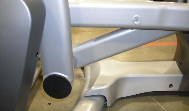
 are completely tightened and flush")
63 chapter 9: ascent trainer specifications and assembly guide 9.4 Leveling the ascent trainer When leveling the Ascent Trainer, make sure that the middle levelers (shown below) are completely tightened and flush with the bottom of the machine. Use only the front 2 levelers to balance out the machine. 59
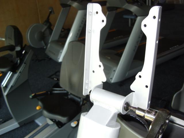
 Pound the spring pin (found in the hardware bag) into the small hole in the TV bracket (Figure A). This is much easier to do before the bracket is installed on the Ascent Trainer.")

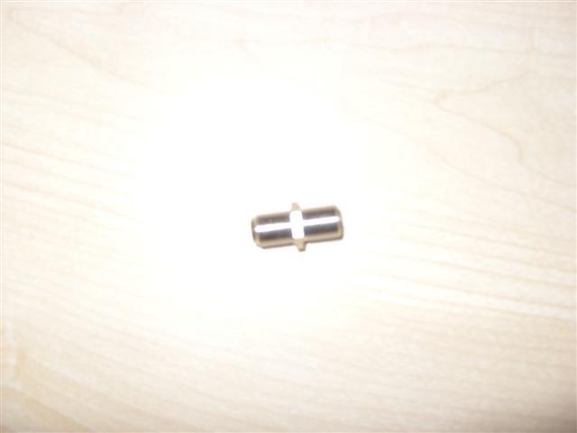
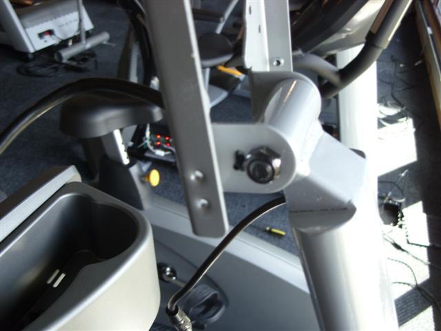
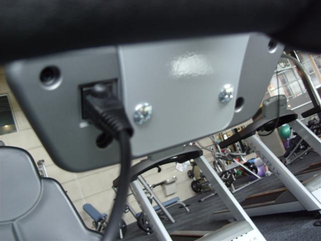
64 chapter 9: ascent trainer specifications and assembly guide 9.5 TV Bracket Installation 1) Remove the bracket, hardware, and TV from their boxes. 2) Pound the spring pin (found in the hardware bag) into the small hole in the TV bracket (Figure A). This is much easier to do before the bracket is installed on the Ascent Trainer. 3) Remove the Matrix Logo plate from the front of the console mast (Figure B). 4) Pull the coax and TV power wires through the hole in the front of the console mast. NOTE: You may need to remove the console to get these wires fished through the hole in the front of the console mast. 5) Attach the coax and TV power wires to the wiring running inside of the TV bracket (Figure C). You will need to use the male to male coax connector shipped in the hardware bag (Figure D). 6) Attach the TV bracket to the console mast using the 4 screws removed in Step 3 (Figure E). 7) Attach both of the long metal pieces (called rabbit ears) to the TV bracket using the long screw and nut found in the hardware bag (Figure F). The user's right side rabbit ear should be installed so that the spring pin lines up with a hole in the rabbit ear to limit the angle of adjustment of the TV (Figure G). 8) Attach the TV to the rabbit ears using 4 screws from the hardware bag (Figure H). 9) Attach the TV controller bracket to the front of the console. The TV controller bracket will mount using the 2 bottom screws holding the console to the console mast (Figure I). 10) Attach the TV controller to the TV controller bracket (Figure J). 11) Connect the TV power wire (Figure K), coax cable signal wire (Figure L), and controller wire (Figure M) to the back of the TV. NOTE: The controller wire will have a tag on both ends, one labeled controller, the other TV. 12) Connect the controller wire to the back of the TV controller (Figure N). 13) Install the cover onto the back of the TV (Figure O). NOTE: There is an extra cover shipped with the TV. 13) Run a coax cable to the base of the Ascent Trainer and plug it into the entertainment port (Figure P). 14) Plug in the TV power adaptor to a wall plug and into the entertainment port at the base of the Ascent Trainer (Figure Q). 15) Use the remote control sent with the TV to perform a channel search to program the TV (Figure R). 16) To perform a channel search, hit MENU, the right arrow once, hit the down arrow to Auto CH Search, and then ENTER. The TV will automatically search for both Analog and Digital channels. Figure A Figure B 60

65 chapter 9: ascent trainer specifications and assembly guide 9.5 TV Bracket Installation - Continued Figure C Figure D Figure E Figure F Figure G Figure H 61

66 chapter 9: ascent trainer specifications and assembly guide 9.5 TV Bracket Installation - Continued Figure I Figure J Figure K Figure L Figure M Figure N 62


67 chapter 9: ascent trainer specifications and assembly guide 9.5 TV Bracket Installation - Continued Figure O Figure P Figure Q Figure R 63
CLASS CYCLE P8000 OWNER'S MANUAL JOHNSON HEALTH TECH. CO., LTD.
 CLASS CYCLE P8000 JOHNSON HEALTH TECH. CO., LTD. No.26, Ching Chuan Rd., Taya Hsiang, Taichung Hsien 428, Taiwan, R.O.C. TEL: +886-4-2566700 FAX: +886-4-2560087 E-mail: sales@johnsonfitness.com http://www.johnsonfitness.com
MAGNETIC CYCLING TRAINER SF-B0419 USER MANUAL
 MAGNETIC CYCLING TRAINER SF-B049 USER MANUAL IMPORTANT: Read all instructions carefully before using this product. Retain owner s manual for future reference. For customer service, please contact: support@sunnyhealthfitness.com
222 Schwinn Recumbent Exercise Bike Parts List Full Size Hardware Chart Product Illustration Assembly Instructions
 222 Schwinn Recumbent Exercise Bike Parts List Full Size Hardware Chart Product Illustration Assembly Instructions FITNESS SAFEGUARDS AND WARNINGS Before starting any exercise program, consult with your
IMPORTANT PRECAUTIONS DANGER! WARNING! CAUTION! SAVE THESE INSTRUCTIONS ENGLISH TO REDUCE THE RISK OF ELECTRICAL SHOCK:
 T3xe T3xh T3xm T3x T1xe T1x 2 IMPORTANT PRECAUTIONS SAVE THESE INSTRUCTIONS When using a treadmill, basic precautions should always be followed, including the following: Read all instructions before using
7130 Lancer Rear Drive Magnetic Commercial Indoor Cycling Bike
 7130 Lancer Rear Drive Magnetic Commercial Indoor Cycling Bike Owner s Manual Made in Taiwan INDEX IMPORTANT SAFETY INFORMATION... 1 EXPLODED DRAWING... 2 PARTS LIST... 3 ASSEMBLY INSTRUCTION... 4-9 USER
BELT DRIVE INDOOR CYCLING BIKE SF-B1712 USER MANUAL
 BELT DRIVE INDOOR CYCLING BIKE SF-B1712 USER MANUAL IMPORTANT! Please retain owner s manual for maintenance and adjustment instructions. Your satisfaction is very important to us, PLEASE DO NOT RETURN
MAGNETIC INDOOR CYCLING BIKE
 MAGNETIC INDOOR CYCLING BIKE SF-B1805 USER MANUAL IMPORTANT! Please retain owner s manual for maintenance and adjustment instructions. Your satisfaction is very important to us, PLEASE DO NOT RETURN UNTIL
MAGNETIC MINI EXERCISE BIKE SF-B0418 USER MANUAL
 MAGNETIC MINI EXERCISE BIKE SF-B018 USER MANUAL IMPORTANT! Please retain owner s manual for maintenance and adjustment instructions. Your satisfaction is very important to us, PLEASE DO NOT RETURN UNTIL
IMPORTANT PRECAUTIONS DANGER! WARNING! CAUTION! SAVE THESE INSTRUCTIONS TO REDUCE THE RISK OF ELECTRICAL SHOCK:
 T7xi T7xe T5x 2 IMPORTANT PRECAUTIONS SAVE THESE INSTRUCTIONS When using a treadmill, basic precautions should always be followed, including the following: Read all instructions before using this equipment.
INDOOR CYCLING BIKE SF-B1110 USER MANUAL
 INDOOR CYCLING BIKE SF-B1110 USER MANUAL IMPORTANT! Read all instructions carefully before using this product. Retain owner s manual for future reference. For customer service, please contact: support@sunnyhealthfitness.com
Misaligned Folds Paper Feed Problems Double Feeds Won t Feed FLYER Won t Run iii
 Operator s Manual Table of Contents Operator Safety... 1 Introduction... 2 Unpacking and Setup... 3 Unpacking... 3 Setup... 4 FLYER Overview... 5 FLYER Diagram... 5 Capabilities... 5 Control Panel... 6
200 PSI COMPRESSORS - MODEL NUMBERS
 200 PSI COMPRESSORS - MODEL NUMBERS 380C AIR COMPRESSOR KIT PART NO. 38033 480C AIR COMPRESSOR KIT PART NO. 48043 380C 480C IMPORTANT: It is essential that you and any other operator of this product read
Pressure Dump Valve Service Kit for Series 3000 Units
 Instruction Sheet Pressure Dump Valve Service Kit for Series 000 Units. Overview The Nordson pressure dump valve is used to relieve hydraulic pressure instantly in Series 00, 400, 500, and 700 applicator
Manual en Español Latino Americano: ASSEMBLY MANUAL / OWNER S MANUAL
 Manual en Español Latino Americano: http://www.schwinnfitness.com ASSEMBLY MANUAL / OWNER S MANUAL Table of Contents Important Safety Instructions - Assembly 3 Safety Warning Labels / Serial Number 4 Specifications
BELT DRIVE PREMIUM INDOOR CYCLING BIKE SF-B1509 USER MANUAL
 BELT DRIVE PREMIUM INDOOR CYCLING BIKE SF-B1509 USER MANUAL IMPORTANT! Read all instructions carefully before using this product. Retain owner s manual for future reference. For customer service, please
PARAMOUNT FITNESS 7.55T/7.85T Treadmill Owner s Manual
 PARAMOUNT FITNESS 7.55T/7.85T Treadmill Owner s Manual Safety Warnings... 4 Introduction... 7 Overview... 7 Power Requirements... 8 Service and Support Information... 9 Initial Setup... 10 Warnings...
Pressure Dump Valve Service Kit for Series 2300 Units
 Instruction Sheet Pressure Dump Valve Service Kit for Series 00 Units. Overview The Nordson pressure dump valve is used to relieve hydraulic pressure instantly in Series 00 applicator tanks when the unit
USER S MANUAL QUESTIONS? CAUTION. Model No. FMEX Serial No. Write the serial number in the space above for reference. Serial Number Decal
 Model No. FMEX81110.0 Serial No. Write the serial number in the space above for reference. USER S MANUAL Serial Number Decal QUESTIONS? If you have questions, or if parts are damaged or missing, please
A U T O O P E N S E R I E S C A P P R E S S O P E R A T O R S M A N U A L
 A U T O O P E N S E R I E S C A P P R E S S O P E R A T O R S M A N U A L Safety Instructions When using your heat press, basic precautions should always be followed, including the following:.. 3. 4. 5.
DeskCycle USER S MANUAL. Ellipse QUESTIONS / PROBLEMS. Order# Support and Contact: See the support link at DeskCycle.com
 DeskCycle Ellipse USER S MANUAL Visit us at www.deskcycle.com for: Usage Tips Calorie Calculator Accessories And More QUESTIONS / PROBLEMS Order# Support and Contact: See the support link at DeskCycle.com
100C Air Compressor Kit
 10010 100C Air Compressor (standard mounting bracket, CE Spec) 10014 100C Air Compressor (no leader hose or check valve, CE Spec) 10016 100C Air Compressor (with Omega Bracket, CE Spec) IMPORTANT: It is
BELT DRIVE INDOOR CYCLING BIKE SF-B1712
 BELT DRIVE INDOOR CYCLING BIKE SF-B1712 USER MANUAL IMPORTANT! Read all instructions carefully before using this product. Retain owner s manual for future reference. For customer service, please contact:
PRO1030 Bi-Directional Assembly Replacement
 PRO1030 Bi-Directional Assembly Replacement 1. Remove both side covers using the Crank and Cover Removal procedure. Fig. 1 2. Disconnect both brake cables (not shown) from the brake (S3611). (Fig. 1) 3.
420C AIR COMPRESSOR KIT PART NO C AIR COMPRESSOR KIT PART NO
 420C AIR COMPRESSOR KIT PART NO. 42042 460C AIR COMPRESSOR KIT PART NO. 46043 420C 460C IMPORTANT: It is essential that you and any other operator of this product read and understand the contents of this
Magnetic Bike. Model No: AENERGISER BODY WORX. Retain this owner s manual for future reference Read and follow all instructions in this owner s manual
 BODY WORX Magnetic Bike Model No: AENERGISER Retain this owner s manual for future reference Read and follow all instructions in this owner s manual Version A 1 EXPLODE DRAWING -02- PARTS LIST AND TOOLS
444C DUAL PERFORMANCE VALUE PACK
 (Chrome) PART NO. 44432 IMPORTANT: It is essential that you and any other operator of this product read and understand the contents of this manual before installing and using this product. SAVE THIS MANUAL
Booster Pump PB4-60 Replacement Kits
 Booster Pump PB4-60 Replacement Kits FOR YOUR SAFETY - This product must be installed and serviced by a contractor who is licensed and qualified in pool equipment by the jurisdiction in which the product
USER GUIDE PREDATOR E620ST STANDING UPPER BODY ERGOMETER REGISTER YOUR PRODUCT AT FIRSTDEGREEFITNESS.COM/SUPPORT
 USER GUIDE PREDATOR E620ST STANDING UPPER BODY ERGOMETER REGISTER YOUR PRODUCT AT FIRSTDEGREEFITNESS.COM/SUPPORT VERSION: 2016 INTRODUCTION WELCOME TO YOUR PREDATOR E620ST Congratulations on your purchase
IMPORTANT SAFETY INSTRUCTIONS
 IMPORTANT SAFETY INSTRUCTIONS CAUTION - To reduce risk of electrical shock: - Do not disassemble. Do not attempt repairs or modifications. Refer to qualified service agencies for all service and repairs.
The MAXX Press DIGITAL CAP OPERATOR S MANUAL
 The MAXX Press DIGITAL CAP OPERATOR S MANUAL Safety Instructions When using your heat press, basic precautions should always be followed, including the following:.. 3. 4. 5. 6. 7. 8. 9. 0.. Read all instructions.
OPERATOR S MANUAL SPREADER. CSS, VNQ [For Combine Harvester AW82V] Original instructions
![OPERATOR S MANUAL SPREADER. CSS, VNQ [For Combine Harvester AW82V] Original instructions](/thumbs/90/102423265.jpg "OPERATOR S MANUAL SPREADER. CSS, VNQ [For Combine Harvester AW82V] Original instructions") OPERATOR S MANUAL SPREADER CSS, VNQ [For Combine Harvester AW82V] en Original instructions Introduction Introduction Please read this operator s manual before using your spreader. We would first like to
OPERATOR S MANUAL SPREADER CSS, VNQ [For Combine Harvester AW82V] en Original instructions Introduction Introduction Please read this operator s manual before using your spreader. We would first like to
Duo/Trio Office Bike Owner s Manual
 Duo/Trio Office Bike Owner s Manual Welcome Congratulations on choosing to enhance your productivity and wellness with LifeSpan. You ve made a healthy decision, as the need for increased amounts of daily
250C-IG COMPRESSOR KIT 12V PART NO C-IG COMPRESSOR KIT 24V PART NO
 250C-IG COMPRESSOR KIT 12V PART NO. 25050 250C-IG COMPRESSOR KIT 24V PART NO. 25058 IMPORTANT: It is essential that you and any other operator of this product read and understand the contents of this manual
INCLINE SLIDE ROWER SF-RW5720 USER MANUAL
 INCLINE SLIDE ROWER SF-RW5720 USER MANUAL IMPORTANT! Read all instructions carefully before using this product. Retain owner s manual for future reference. For customer service, please contact: support@sunnyhealthfitness.com
SPINNER CHRONO GETTING STARTED GUIDE. Welcome to a personalized fitness experience for your members
 SPINNER CHRONO GETTING STARTED GUIDE Welcome to a personalized fitness experience for your members The Spinner Chrono is a premium bike offering your members a high degree of adjustability, comfort, and
PROPORTIONING VALVE. Model 150 INSTRUCTION MANUAL. March 2017 IMS Company Stafford Road
 PROPORTIONING VALVE Model 150 INSTRUCTION MANUAL March 2017 IMS Company 10373 Stafford Road Telephone: (440) 543-1615 Fax: (440) 543-1069 Email: sales@imscompany.com 1 Introduction IMS Company reserves
SPINNER RIDE GETTING STARTED GUIDE. Welcome to a personalized fitness experience for your members
 This addendum accompanies your equipment documentation and is additional information concerning the heart rate features for your equipment and console. Important The heart rate feature is intended for
400C & 450C DUAL PERFORMANCE VALUE PACKS
 (Chrome) PART NO. 40013 (Silver) PART NO. 45012 (Chrome) PART NO. 45013 IMPORTANT: It is essential that you and any other operator of this product read and understand the contents of this manual before
User Manual GRI- 1500Li
 User Manual GRI- 1500Li Your Cart Tek caddy cart was thoroughly quality control checked and road tested before being shipped to your address. We do everything possible to assure that your caddy is in perfect
Lectric Cycles Mid-Drive Electric Motor Installation
 Lectric Cycles Mid-Drive Electric Motor Installation This write-up describes the installation of a Lectric Cycles electric motor. The model is the e-rad Mid-Drive 750 Watt conversion kit, installed on
D I G I T A L C L A M
 The MAXX Press D I G I T A L C L A M OPERATOR S MANUAL 6 x0 x5 5 x5 Safety Instructions When using your heat press, basic precautions should always be followed, including the following:.. 3.. 5. 6. 7.
TrekMill USER'S MANUAL MM5050
 Read the safety and comfort guide in this manual before using this equipment. USER'S MANUAL TrekMill MM5050 Serial Number: Date Purchased: Find the serial number in the location shown below. CONTENTS Safety
DM-MBRD (English) Dealer's Manual. ROAD MTB Trekking. City Touring/ Comfort Bike. Rear Derailleur SLX RD-M7000 DEORE RD-M6000
 Dealer's Manual. ROAD MTB Trekking. City Touring/ Comfort Bike. Rear Derailleur SLX RD-M7000 DEORE RD-M6000") (English) DM-MBRD001-04 Dealer's Manual ROAD MTB Trekking City Touring/ Comfort Bike URBAN SPORT E-BIKE Rear Derailleur SLX RD-M7000 DEORE RD-M6000 CONTENTS IMPORTANT NOTICE... 3 TO ENSURE SAFETY... 4
(English) DM-MBRD001-04 Dealer's Manual ROAD MTB Trekking City Touring/ Comfort Bike URBAN SPORT E-BIKE Rear Derailleur SLX RD-M7000 DEORE RD-M6000 CONTENTS IMPORTANT NOTICE... 3 TO ENSURE SAFETY... 4
BELT DRIVE PREMIUM INDOOR CYCLING BIKE SF-B1509 USER MANUAL
 BELT DRIVE PREMIUM INDOOR CYCLING BIKE SF-B1509 USER MANUAL IMPORTANT! Please retain owner s manual for maintenance and adjustment instructions. Your satisfaction is very important to us, PLEASE DO NOT
97C COMPRESSOR KIT 12V PART NO C COMPRESSOR KIT 24V PART NO C COMPRESSOR KIT PART NO
 97C COMPRESSOR KIT 12V PART NO. 00097 97C COMPRESSOR KIT 24V PART NO. 02497 98C COMPRESSOR KIT PART NO. 00098 97C 98C IMPORTANT: It is essential that you and any other operator of this product read and
250C-IG COMPRESSOR KIT 12V PART NO C-IG COMPRESSOR KIT 24V PART NO
 250C-IG COMPRESSOR KIT 12V PART NO. 25050 250C-IG COMPRESSOR KIT 24V PART NO. 25058 IMPORTANT: It is essential that you and any other operator of this product read and understand the contents of this manual
INDOOR BIKE MANUAL
 INDOOR BIKE 91022 MANUAL 91022 INSTRUCTIONS FOR USE 1) The model 91022 is designed to be used as light commercial use or home use. It has a fixed wheel driven flywheel and should be used under professional
TWIST-IN STEPPER SF-S0636 USER MANUAL
 TWIST-IN STEPPER SF-S0636 USER MANUAL IMPORTANT! Please retain owner s manual for maintenance and adjustment instructions. Your satisfaction is very important to us, PLEASE DO NOT RETURN UNTIL YOU HAVE
Model PSI Compressor with 3-Gallon Air Tank 12VDC
 Model 6350 150 PSI Compressor with 3-Gallon Air Tank 12VDC IMPORTANT: It is essential that you and any other operator of this product read and understandd the contents of this manual before installing
Motorized Treadmill Owner s Manual
 Motorized Treadmill Owner s Manual HS212TM FORCE PLEASE READ ALL INSTRUCTIONS IN THE OWNER'S MANUAL. CAREFULLY BEFORE ASSEMBLY AND USE OF THE TREADMILL, AND KEEP IT FOR FUTURE REFERENCE. 0 CONTENTS------------------------------------------------------------------------------------1
Procedure Troubleshooting the Interconnect Cables
 Procedure 6.1 - Troubleshooting the Interconnect Cables Troubleshooting the upper interconnect cable 1. Remove the display housing per Procedure 7.13. Disconnect the upper interconnect cable from the upper
Fiber Cable Puller with Tuf-Lugger lite
 7 OPERATING INSTRUCTION MANUAL Fiber Cable Puller with Tuf-Lugger lite Copyright 2015 DCD Design & Manufacturing Ltd. Revision 1.0 IMPORTANT SAFETY INSTRUCTIONS READ ALL INSTRUCTIONS BEFORE USING The Fiber
The Walkstation. User Instructions. FitWork Walkstation
 The Walkstation User Instructions FitWork Walkstation Walkstation Safety Instructions When using the Walkstation, basic safety precautions should always be followed, including, but not limited to, the
USER GUIDE PREDATOR E620ST STANDING UPPER BODY ERGOMETER
 USER GUIDE PREDATOR E620ST STANDING UPPER BODY ERGOMETER Introduction WELCOME TO YOUR PREDATOR E620ST Congratulations on your purchase the Predator is constructed for high intensity, powerful workouts.
Santa Fe Cycles Assembly Guide Introduction
 Santa Fe Cycles Assembly Guide Introduction Congratulations on your purchase of your new Santa Fe bicycle. You have purchased a bicycle that has many features and qualities. Please take a few minutes and
Final Assembly Instructions Bikes with Threaded Headsets
 Final Assembly Instructions Bikes with Threaded Headsets Thank you for buying your new bicycle from L.L.Bean. Read these instructions carefully before beginning the final assembly. Prior to shipping, our
Assembly Tools. Assembly will take 1-2 hours
 Assembly Tools Included in your parts box: Pedals Quick release skewer Reflectors (if not already installed) Toolkit (4+5mm combo Allen wrench, 13+15mm combo open-end wrench) Helpful Tools: Scissors (for
400H HARDMOUNT AIR COMPRESSOR KIT PART NO H HARDMOUNT AIR COMPRESSOR KIT PART NO
 400H HARDMOUNT AIR COMPRESSOR KIT PART NO. 40042 450H HARDMOUNT AIR COMPRESSOR KIT PART NO. 45042 400H 450H IMPORTANT: It is essential that you and any other operator of this product read and understand
Gerber Sabre 404 and 408 Installation Instructions
 1 TITLE: Gerber FastFact # Supplied by: Last Modified: Summary: Gerber Sabre 404 and 408 Installation Instructions 5002 Gerber Service November 13, 2001 This document provides the installation and set-up
OEM Manual MODEL 2305 ECONOMICAL DIGITAL SINGLE CYLINDER SCALE
 OEM Manual MODEL 2305 ECONOMICAL DIGITAL SINGLE CYLINDER SCALE 1 These instructions generally describe the installation, operation, and maintenance of subject equipment. The manufacturer reserves the right
AC1810 / AC1810-A TECHNICAL SPECIFICATIONS. Operating Pressure psi ( kgs/cm²) [AC1810] Displacement. Net Weight
![AC1810 / AC1810-A TECHNICAL SPECIFICATIONS. Operating Pressure psi ( kgs/cm²) [AC1810] Displacement. Net Weight](/thumbs/83/88369739.jpg "AC1810 / AC1810-A TECHNICAL SPECIFICATIONS. Operating Pressure psi ( kgs/cm²) [AC1810] Displacement. Net Weight") Technical Specifications Operating Instructions Maintenance Information Troubleshooting Guide Parts Diagrams AC1810 / AC1810-A THE EVOLUTION OF PERFECTION CAUTION: Before attempting to use or service this
Technical Specifications Operating Instructions Maintenance Information Troubleshooting Guide Parts Diagrams AC1810 / AC1810-A THE EVOLUTION OF PERFECTION CAUTION: Before attempting to use or service this
200 PSI HIGH-FLOW AIR SOURCE KIT
 200 PSI HIGH-FLOW AIR SOURCE KIT 50% Duty Compressor on 2.0 Gallon Air Tank PART NO. 20008 IMPORTANT: It is essential that you and any other operator of this product read and understand the contents of
200 PSI FAST-FILL AIR SOURCE KIT
 200 PSI FAST-FILL AIR SOURCE KIT 55% Duty Compressor on 2.0 Gallon Air Tank PART NO. 20007 IMPORTANT: It is essential that you and any other operator of this product read and understand the contents of
TECHNICAL INFORMATION
 TECHNICAL INFORMATION Model No. Description RP2300FC, RP2301FC Router CONCEPT AND MAIN APPLICATIONS Models RP2300FC and RP2301FC are upgraded sister tools of our current plunge-type electronic router Model
BR-2444 ROWING MACHINE
 BR-2444 ROWING MACHINE Important Safety Information Please keep this manual in a safe place for reference. 1. It is important to read this entire manual before assembling and using the equipment. Safe
Final Assembly Instructions Bikes with Quill Stems
 Final Assembly Instructions Bikes with Quill Stems Thank you for buying your new bicycle from L.L.Bean. Read these instructions carefully before beginning the final assembly. Prior to shipping, our expert
MODEL NUMBER: PSI AIR SOURCE KIT 200 PSI Compressor on 2.0 Gallon 200 PSI Air Tank
 IMPORTANT SAFETY INSTRUCTIONS CAUTION - To reduce risk of electrical shock or Electrocution: MODEL NUMBER: 20008 200 PSI AIR SOURCE KIT 200 PSI Compressor on 2.0 Gallon 200 PSI Air Tank IMPORTANT: It is
Training with the Seattle Wooden Rower. Contents CAUTION CAUTION. 1. Carton contents of the Seattle Wooden Rower. 2. Assembly.
 Training with the Seattle Wooden Rower Contents. As with any piece of fitness equipment, consult a physician before starting your exercise program.. Follow instructions provided in this manual for correct
icreasepro Creaser Operators Manual
 6-2013 Version 3.0 icreasepro Creaser Operators Manual WWW.MBMCORP.COM 800-223-2508 TABLE OF CONTENTS SPECIFICATIONS.1a SAFETY PROCEDURES/CARE & MAINTENANCE..1b COMPONENT IDENTIFICATION 2 TOUCH SCREEN
CycleOps Pro Series Indoor Cycles
 CycleOps Pro Series Indoor Cycles User Guide 400 Pro 300 Pro 200 Pro 100 Pro Deutsche Anweisungen www.cycleops.com/userguide Istruzioni italiane www.cycleops.com/userguide Nederlandse instructies www.cycleops.com/userguide
42045 Heavy Duty ADA Base Model Kit: 85/105 PSI (ADA Compressor Only) Heavy Duty ADA Base Model Kit: 110/145 PSI (ADA Compressor Only)
 Heavy Duty ADA Base Model Kit: 110/145 PSI (ADA Compressor Only)") 42045 Heavy Duty ADA Base Model Kit: 85/105 PSI (ADA Compressor Only) 42047 Heavy Duty ADA Base Model Kit: 110/145 PSI (ADA Compressor Only) 45052 Constant Duty ADA Base Model Kit: 85/105 PSI (ADA Compressor
42045 Heavy Duty ADA Base Model Kit: 85/105 PSI (ADA Compressor Only) 42047 Heavy Duty ADA Base Model Kit: 110/145 PSI (ADA Compressor Only) 45052 Constant Duty ADA Base Model Kit: 85/105 PSI (ADA Compressor
Shoreline Cantilever Lift 2500lb Capacity Models: (108" inside width) - Part # (120" inside width) - Part #
 - Part # (120 inside width) - Part #") Shoreline Cantilever Lift 2500lb Capacity Models: 25108 (108" inside width) - Part # 1017402 25120 (120" inside width) - Part # 1017403 1. 2. 3. 4. 5. CAUTION - PUT SAFETY FIRST Before attempting to install
Shoreline Cantilever Lift 2500lb Capacity Models: 25108 (108" inside width) - Part # 1017402 25120 (120" inside width) - Part # 1017403 1. 2. 3. 4. 5. CAUTION - PUT SAFETY FIRST Before attempting to install
MODEL NUMBER: M20005 AIR SOURCE KIT. 30% Duty Compressor on. 2.0 Gallon Air Tank SAVE THIS MANUAL FOR FUTURE REFERENCE
 MODEL NUMBER: M20005 AIR SOURCE KIT 30% Duty Compressor on 2.0 Gallon Air Tank SAVE THIS MANUAL FOR FUTURE REFERENCE USER MANUAL IMPORTANT SAFETY INSTRUCTIONS CAUTION - To reduce risk of electrical shock
 www.myrower.com support@myrower.com ASSEMBLY Congratulations on purchasing the MyRower! Please see the following pages for instructions on assembling your MyRower. Bits bag contents: Rail Cross Bolt (90mm)
Rocky Mountain Element Technical Manual. Rev B
 Rocky Mountain Element Technical Manual Rev B 1 Table of Contents Materials Required... 3 Suspension Pivot Torque Guide... 4 Small Parts Torque Guide... 5 Assembly Instructions... 6 1) Bearing Installation...
CHAIN DRIVE PREMIUM INDOOR CYCLING BIKE SF-B1509C USER MANUAL
 CHAIN DRIVE PREMIUM INDOOR CYCLING BIKE SF-B509C USER MANUAL WARNING! Your indoor cycling bike is not designed for reverse pedaling! Failure to comply with this warning may result in permanent damage to
Final Assembly Instructions Bikes with Threaded Headsets
 Final Assembly Instructions Bikes with Threaded Headsets Thank you for buying your new bicycle from L.L.Bean. Read these instructions carefully before beginning the final assembly. Prior to shipping, our
Troubleshooting Guide
 Troubleshooting Guide This troubleshooting guide outlines quick fixes to the most common technical questions about the ElliptiGO. If the problem persists or you feel uncomfortable performing these actions,
2,500/4,000 LB Easy Riser Vertical Cable Feighner Lift
 2,500/4,000 LB Easy Riser Vertical Cable Feighner Lift CAUTION - PUT SAFETY FIRST 1. Before attempting to install or operate this lift, study and fully understand the proper operating procedures and safety
DM-MARD (English) Dealer's Manual. ROAD MTB Trekking. City Touring/ Comfort Bike REAR DERAILLEUR XTR RD-M9100 RD-M9120
 Dealer's Manual. ROAD MTB Trekking. City Touring/ Comfort Bike REAR DERAILLEUR XTR RD-M9100 RD-M9120") (English) DM-MARD001-00 Dealer's Manual ROAD MTB Trekking City Touring/ Comfort Bike URBAN SPORT E-BIKE REAR DERAILLEUR XTR RD-M9100 RD-M9120 CONTENTS CONTENTS...2 IMPORTANT NOTICE...3 TO ENSURE SAFETY...4
(English) DM-MARD001-00 Dealer's Manual ROAD MTB Trekking City Touring/ Comfort Bike URBAN SPORT E-BIKE REAR DERAILLEUR XTR RD-M9100 RD-M9120 CONTENTS CONTENTS...2 IMPORTANT NOTICE...3 TO ENSURE SAFETY...4
USER MANUAL. you pedal, something amazing happens
 TM USER MANUAL you pedal, something amazing happens THANK YOU! In our humble beginnings we ran a bike-powered smoothie booth at Northern California music festivals called The Juice Pedaler. We saw the
Magnetic-Resistance Rower NS-40503RW. Model NS-40503RW. Retain This Manual for Reference ASSEMBLY & OWNER'S MANUAL
 NOTE: Please read all instructions carefully before using this product Table of Contents Safety Notice Hardware Pack Magnetic-Resistance Rower NS-40503RW Assembly Instruction Parts List Warranty Ordering
OPERATING and MAINTENANCE INSTRUCTIONS MAXIS 3K Puller (M3K-M)
") OPERATING and MAINTENANCE INSTRUCTIONS MAXIS 3K Puller (M3K-M) 04/17 (M3K-M) READ AND UNDERSTAND ALL OF THE INSTRUCTIONS AND SAFETY INFORMATION IN THIS MANUAL BEFORE OPERATING OR SERVICING THIS TOOL TABLE
OPERATING and MAINTENANCE INSTRUCTIONS MAXIS 3K Puller (M3K-M) 04/17 (M3K-M) READ AND UNDERSTAND ALL OF THE INSTRUCTIONS AND SAFETY INFORMATION IN THIS MANUAL BEFORE OPERATING OR SERVICING THIS TOOL TABLE
Freedom8 ShoeBox Compressor Manual
 Freedom8 ShoeBox Compressor Manual Warning!! This product is not a toy! Use or misuse can cause severe injury or death! Use only with adult supervision. This unit is only to be used with tanks, hoses and
OPERATING and MAINTENANCE INSTRUCTIONS MAXIS 6K Puller (M6K-M)
") OPERATING and MAINTENANCE INSTRUCTIONS MAXIS 6K Puller (M6K-M) READ AND UNDERSTAND ALL OF THE INSTRUCTIONS AND SAFETY INFORMATION IN THIS MANUAL BEFORE OPERATING OR 04/17 (M6K-M) SERVICING THIS TOOL TABLE
OPERATING and MAINTENANCE INSTRUCTIONS MAXIS 6K Puller (M6K-M) READ AND UNDERSTAND ALL OF THE INSTRUCTIONS AND SAFETY INFORMATION IN THIS MANUAL BEFORE OPERATING OR 04/17 (M6K-M) SERVICING THIS TOOL TABLE
24L OIL FREE AIR COMPRESSOR MODEL NO: TIGER 7/250 PART NO: OPERATION & MAINTENANCE INSTRUCTIONS LS10/13
 24L OIL FREE AIR COMPRESSOR MODEL NO: TIGER 7/250 PART NO: 2244030 OPERATION & MAINTENANCE INSTRUCTIONS LS10/13 INTRODUCTION Thank you for purchasing this product. Before attempting to use this product,
A4s Operation Manual
 A4s Operation Manual Safety Instruction Please read this manual carefully, also with related manual for the machinery before use the controller. For installing and operating the controller properly and
U.S. Patent No. 7,922,246. Patents Pending
 U.S. Patent No. 7,922,246 Patents Pending 2 Table of Contents Page General Information... 3 Warnings and Cautions... 4 Tools... 6 SmartDock Parts... 6 Initial Set-Up and Adjustment... 7 Select Valve Retaining
Console Owner s Manual
 Console Owner s Manual DT3 Treadmill Base Owner s Manual TR800B, TR1200B, TR5000B Table of Contents Welcome Getting Started Welcome Warranty Registration Safety Treadmill Base Specifications Unique Features
To save this document, scroll up and select the download icon
 Thank you for purchasing a RustySpokes Softcruise. We know you are going to enjoy the bike, but if you had it shipped to you, there are a few things you need to do to assemble the bike. The seat, pedals
USER MANUAL
 C Cimarron Sports 1-888-816-6517 www.cimarronsports.com Combo Pitching Machine USER MANUAL TABLE OF CONTENTS Thank you for purchasing the Cimarron Combo Pitching Machine. The Cimarron Combo Pitching Machine
Med Aire Alternating Pressure Pump and Pad System
 User Manual Med Aire Alternating Pressure Pump and Pad System 14002E 14001E Symbols & Statements NOTE Indicates some tips or some information users should be aware of. CAUTION Indicates correct operating
A4 Operation Manual. Fig.1-1 Controller Socket Diagram
 A4 Operation Manual Safety Instruction Please read this manual carefully, also with related manual for the machinery before use the controller. For installing and operating the controller properly and
Shifting Lever. RAPIDFIRE Plus 11-speed
 (English) DM-SL0005-04 Shifting Lever Dealer's Manual RAPIDFIRE Plus 11-speed MTB XTR SL-M9000 DEORE XT SL-M8000 CONTENTS IMPORTANT NOTICE... 3 TO ENSURE SAFETY... 4 LIST OF TOOLS TO BE USED... 7 INSTALLATION...
TECHNICAL INFORMATION
 TECHNICAL INFORMATION Models No. TD0101, TD0101F Description Impact Driver L PRODUCT P 1/ 14 CONCEPT AND MAIN APPLICATIONS Models TD0101 and TD0101F are cost-competitive 100N.m-class impact driver developed
Parts List. Description. Additional Considerations. Installation Instructions. Dual/Elite Hydraulic Treadmill Kit (supplied by EPI)
") Page 1 of 9 Parts List Dual/Elite Hydraulic Treadmill Kit (supplied by EPI) Qty Description Treadmill Body 1 Treadmill Power Unit (per Treadmill Body) 2 Treadmill Decks (per Treadmill Body) 1 Treadmill
Page 1 of 9 Parts List Dual/Elite Hydraulic Treadmill Kit (supplied by EPI) Qty Description Treadmill Body 1 Treadmill Power Unit (per Treadmill Body) 2 Treadmill Decks (per Treadmill Body) 1 Treadmill
Nexus. Dealer's Manual. ROAD MTB Trekking. City Touring/ Comfort Bike SG-3R40 SG-3R45 SG-3R75 SG-3R75-A SG-3R75-B SG-3D55 SG-3C41
 (English) DM-SG0005-01 Dealer's Manual ROAD MTB Trekking City Touring/ Comfort Bike URBAN SPORT E-BIKE Nexus SG-3R40 SG-3R45 SG-3R75 SG-3R75-A SG-3R75-B SG-3D55 SG-3C41 SL-3S35-E SL-3S41-E SL-3S42-E SM-BC03
SG-7R46 SG-7R45 BR-IM41-R CJ-7S40 WARNING CAUTION SERVICE INSTRUCTIONS. Inter-7 Hub. Inter-M Brake Cassette joint NOTE:
 t WARNING It is important to completely understand the operation of your bicycle's brake system. Improper use of your bicycle's brake system may result in a loss of control or an accident, which could
Assembly Tools. Assembly will take about an hour
 Assembly Guide Assembly Tools Included in your parts box: Pedals Toolkit (4+5mm combo Allen wrench, 13+15mm combo open-end wrench) Touch-up paint Spare fuses (for battery) Assembly will take about an hour
VERTICAL AIR COMPRESSORS
 VERTICAL AIR COMPRESSORS MODEL NO: VE15C150, VE18C150, VE25C150 PART NO: 2226010, 2226020, 2226025 OPERATION & MAINTENANCE INSTRUCTIONS LS0715 INTRODUCTION Thank you for purchasing this CLARKE Vertical