Supplementary Installation and Operating Instructions. Variable Area Flow Meters SGK-1 Ex SGK-2 Ex SGK-3 Ex. Category: II 2G Ex IIC II 3G Ex IIC
|
|
|
- Joy Perkins
- 5 years ago
- Views:
Transcription
1 Supplementary Installation and Operating Instructions Variable Area Flow Meters SGK-1 Ex SGK-2 Ex SGK-3 Ex Category: II 2G Ex IIC II 3G Ex IIC
2 Contents 1 General safety directions Main safety features Category / zone Ignition protection types Temperature classes Operating pressure Static electricity Static discharge Identification Installation and setup Electrical connection Pin assignments Connection cable Ground connector Start-up Service Dismantling Electrical connection Process connections Maintenance Annex TÜV statement [Technical Control Board] Declaration of conformity
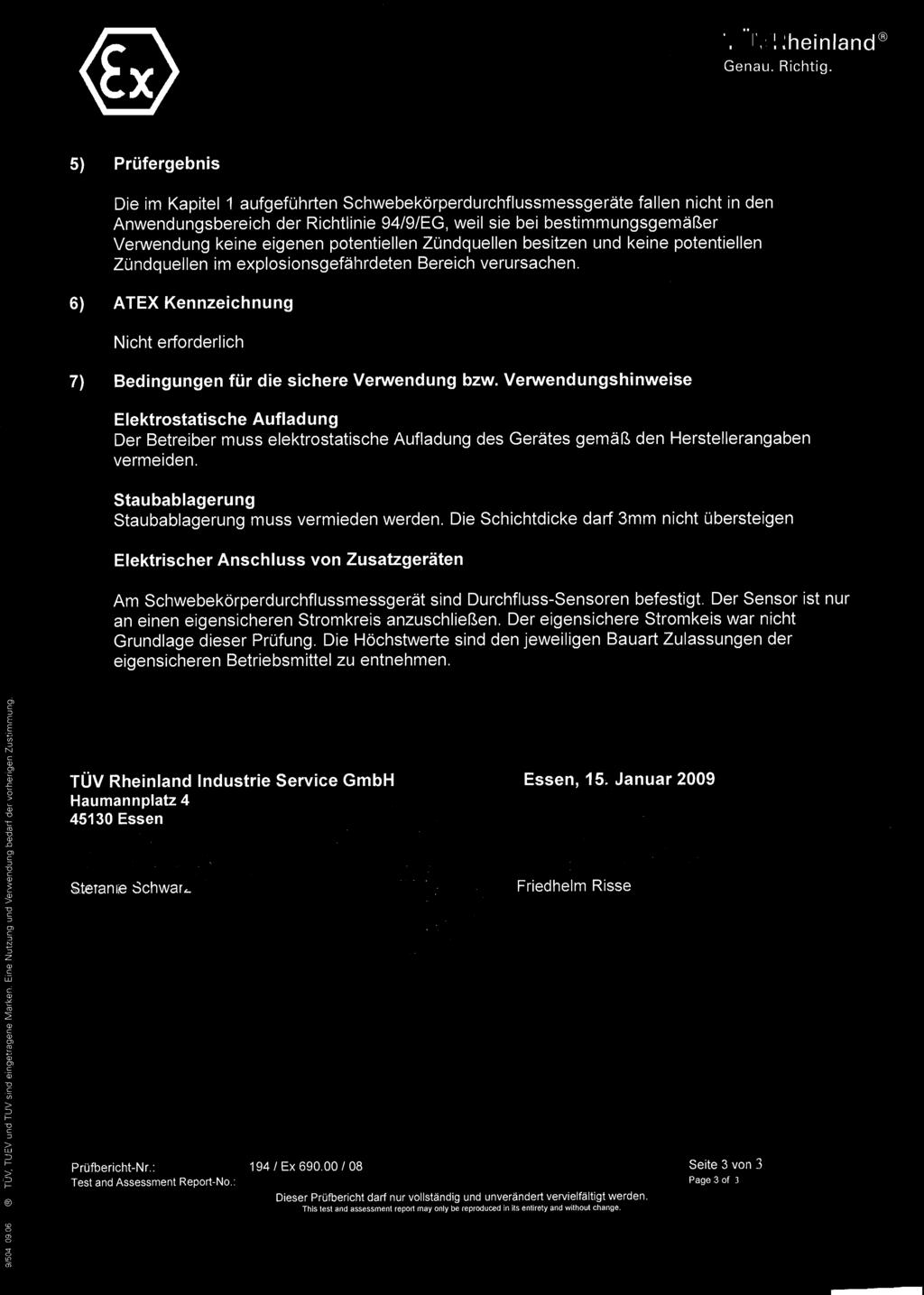
3 1 General safety directions This supplement to the installation and operating instructions is valid for explosion protection designs of variable area flow meters of the following series: SGK-1 Ex SGK-1-MSK1 Ex SGK-1-MSK12 Ex SGK-1-MSKW Ex SGK-1-RC Ex SGK-2 Ex SGK-2-MSK1 Ex SGK-2-MSK12 Ex SGK-2-MSKW Ex SGK-3 Ex SGK-3-MSK1 Ex SGK-3-MSK12 Ex SGK-3-MSKW Ex It supplements the installation and operating instructions for the designs not for protection from explosions. The information in these instructions only contains data that are related to explosion protection. The technical information of the installation and operating instructions for the designs not for protection against explosions remain valid unchanged, as long as they are not excluded or replaced by these instructions. The variable area flow meters of the series SGK-1 Ex SGK-2 Ex SGK-3 Ex have been tested by TÜV Rheinland according to the European Directive 2014/34/EU per EN :2007 and EN :2007 for use in potentially explosive areas using the TÜV test report 194/Ex690.00/08 Danger! Danger of explosion can result from incorrect handling. Installation, set up, commissioning and service of explosion protected operating material must only be performed by personnel trained in explosion protection ( competent person ). -3-
4 2 Main safety features 2.1 Category / zone Variable area flow meters of type: SGK-1 Ex SGK-2 Ex SGK-3 Ex are designed for use in Category 2 according to directive 2014/34/EU and suitable as per EN 60079/14 for use in Zone 1 and Zone 2 (refer to section 9.1 and 9.2). 2.2 Ignition protection types The electrical circuits of the limit indicator (reed contacts/rc-contacts) are designed in the ignition protection type intrinsically safe of category ia. They may only be operated with approved and suitable switch amplifiers, whereby the connection values are limited according to Namur (ssee section 4.1). Variable area flow meters of type: SGK-1 Ex SGK-2 Ex SGK-3 Ex do not fall under 2014/34/EU (also see section 9.1). -4-
5 2.3 Temperature classes Variable area flow meters of type: SGK-1 Ex SGK-2 Ex SGK-3 Ex are allowed only in specifically described temperature classes (see Table 1). The ambient temperature T amb, medium temperature T m and the material of the variable area flow meter are listed in the table. Table 1 Maximum permissible ambient/medium temperatures in C when used in temperature class T6-T1. Material of floats and collectors Aluminium/ /Hastelloy PVDF/PTFE PVC PP Temperature class T6 T6 T6-1 T6 T amb : < 40 C T amb: < 40 C T amb : > 0 C < 40 C T amb: > 0 C < 40 C T m : < 70 C T m: < 70 C T m : < 40 C Tm: < 70 C T5 T5 T5-T1 T amb : < 40 C T amb : < 40 C T amb : > 0 C < 40 C T m: < 85 C T m : < 85 C T m : < 85 C T4-T1 T4-T1 T amb: < 40 C : < 40 C Tamb T m : < 100 C : < 100 C Tm The tables take into consideration the following parameters for determining the permissible temperature class: Ambient temperature T amb Medium temperature T m Material of the float -5-
6 2.4 Operating pressure Glass size Max. operating pressure in bar (pmax) 4; 5; 6; 9,5 ;10; Static electricity With variable area flow meters it is basically possible for the electrostatic field, which is generated in the interior of the measuring tube, to reach to the exterior of the device. Variable area flow meters of type: SGK-1 Ex SGK-2 Ex SGK-3 Ex are therefore to be permanently grounded (see section 4). Danger! Danger of explosion can result from incorrect connection. The operating company is responsible for installing error free grounding of the process line. 2.6 Static discharge Surfaces can be electrostatically, combustibly charged during cleaning (e.g. Plexiglas protection on viewing window). These surfaces are marked with the shown adhesive label. Caution! Measures against static charging Do not rub the plastic surface. Clean surfaces only with damp cloth. The marked locations may be cleaned only with a damp, lint-free cloth. In addition, caution should be taken not to rub against these surfaces with clothing, since static charge can occur at any time. Dust deposits on the housing of the variable area flow meter are also to be removed with a damp cloth. The deposits must not exceed a thickness of 3 mm. -6-

7 3 Identification The identification of the entire device is done on the sleeve parallel to the viewing window with the following rating plates: SGK-2 Year P max Tag No. SN Year of manufacture Max. allowable operating pressure Measurement point marking Serial number Composition of the serial number nnnnn-mmm-yy Example: Order number Device no. 13 in order with year of manufacture
8 4 Installation and setup Danger! Danger of explosion can result from incorrect handling. Installation and setup of explosion protected operating material must only be performed by personnel trained in explosion protection. The instructions of the installation and operating instructions and the supplement to the installation and operating instructions are absolutely to be followed here. Calibration of the variable area flow meters with respect to the area of use is to be checked by inspection of the rating plate. The variable area flow meter is to be grounded (also refer to the illustration in section 4.4). If the equipment is not sufficiently grounded via the process line, an additional ground connection is to be created via the ground connection on the back of the sleeve. The connection only guarantees an electrostatic connection of the equipment and does not meet the requirements of a potential equalization connection. The equipment must be operated with an upstream throttle valve if possible pressure surges in the piping cannot be operationally avoided. 4.1 Electrical connection The simple, intrinsically safe reed contact is fastened to the variable area flow meter. This reed contact must only be done by a type-approved, suitable switch amplifier with intrinsically safe electrical circuits. The following maximum values must be observed: Characteristic data Limit value switch Ui [V] Ii [ma] MSK1 Ex MSK12 Ex MSKW Ex 20 V 40 ma RC N3 RC N3 8 VDC 1 ma/3 ma These limit value switches do not assume safety relevant functions within the system. -8-

9 4.2 Pin assignments The electrical connection of the installed limit value switch is described in the installation and operating instructions and pictured on the product label. For the Ex design, the remark 500 V proofed must be on the contact label as shown in the following illustration. In addition, the type designation also contains Ex. Only equipment with this tested and marked contact is allowed for operation in the Ex area. The operating company of the system must ensure that the contact label shown below is present on the flow meter. Ex designation Warning! This remark must be present on the label to be allowed to operate the equipment in the Ex area 4.3 Connection cable The connection cable for the intrinsically safe electrical circuits is to be selected according to the valid installation standard (e.g. EN ). Summed current generation between different, intrinsically safe electrical currents of the variable area flow meter is to be avoided. -9-
10 4.4 Ground connector The following illustration shows a principle sketch of the connection of the ground cable with the process line. This ground cable must be connected with the process line resp. the grounded dashboard before starting up equipment of type: SGK-1 Ex SGK-2 Ex SGK-3 Ex dashboard SGK Ex grounding connection 5 Start-up Before start-up, the following tests are to be performed: 1. Qualification testing for sufficient corrosion resistance to the measuring media of the materials used for measurement parts and the used sealing materials. 2. Connect the installed, intrinsically safe reed contacts correctly. 3. Electronically ground the measurement equipment (also see illustration in section 4.4) 4. To prevent pressure surges, the operating company must ensure that the device is run with a continuous volume flow. Do not use solenoid valves! -10-
11 6 Service The variable area flow meters of type: SGK-1 Ex, SGK-2 Ex, SGK-3 Ex are maintenance free under normal operating conditions and proper usage. In unfavourable operating modes, adverse measurement functions can occur due to soiling of the measuring glass or the variable area flow meter. In this case a cleaning of the measurement glass and the variable area flow meter is to be performed according to the installation and operating instructions. Alternatively, the device can be sent to Kirchner und Tochter GmbH for cleaning. Danger! Danger of explosion can result from incorrect handling. The service of explosion protected operating material must only be performed by personnel trained in explosion protection. Systems in potentially explosive areas must be regularly inspected for their proper condition. The following tests must be performed regularly: Visual inspection of the housing, measurement glass and connection pieces for damage or corrosion. Check the measurement parts for leaks. Include the variable area flow meter in the regular pressure tests of the process line. Visual inspection of the variable area flow meter collectors (must be replaced if there is brittleness) Dust deposits on the equipment must not exceed a thickness of 3 mm. The equipment is to be thoroughly cleaned with a damp cloth. -11-
12 7 Dismantling 7.1 Electrical connection Disassembly should be performed with the power off if at all possible. If this is not possible, the basic conditions for intrinsic safety (e.g. no grounding or connection of different intrinsically safe electrical currents) must be observed during disassembly. 7.2 Process connections Danger! Danger of injury due to media escaping under pressure. The lines in which the variable area flow meter is installed are to be discharged before disassembly. Depending on the medium, damage e.g. to the respiratory system or the skin may occur. Uncontrolled discharge of residual liquid from the measurement piece is to be avoided. For environmentally critical measuring media, all parts which have been in contact with the media are to be decontaminated carefully after removal. Removal and installation is the responsibility of the operating company. 8 Maintenance Maintenance, which is relevant to safety in regards to explosion protection, is only to be performed by the manufacturer, their agents or supervised by authorised technicians. -12-

13 9 Annex 9.1 TÜV statement [Technical Control Board] -13-
14 -14-

15 -15-
16 9.2 Declaration of conformity -16-
17 Notes -17-
18 Notes -18-
19 Notes -19-
20 The devices from Kirchner und Tochter have been tested in compliance with applicable EC/EU CE-regulations of the European Community. The respective declaration of conformity is available on request. Subject to change without notice. The current valid version of our documents can be found at The Kirchner und Tochter QM-System is certified in accordance with DIN EN ISO 9001:2015. The quality is systematically adapted to the continuously increasing demands.
DK46 - DK800 Supplementary instructions
 DK46 - DK800 Supplementary instructions Variable area flowmeter Device category II2G with electrical internals Additional Ex manual KROHNE CONTENTS DK46 - DK800 1 Safety instructions 3 1.1 General... 3
VA FLOWMETERS Supplementary Instructions
 VA FLOWMETERS Supplementary Instructions Variable area flowmeters without electrical built-ins Equipment category II 2 G, II 2 D KROHNE CONTENTS VA FLOWMETERS 1 General notes 3 2 Safety instructions 4
VS18/26 with PROFINET and EtherNet/IP Interface. ATEX Installation Instructions
 VS18/26 with PROFINET and EtherNet/IP Interface ATEX Installation Instructions INDEX 1. INTENDED USAGE 3 2. OPERATING MANUAL ATEX 4 2.1 General conditions 4 2.2 Installation 5 2.3 Operating 5 2.4 Failures
Installation and Operating Instructions Bypass Flow Meter DST
 Installation and Operating Instructions Bypass Flow Meter DST DST_gb_A4_1.0.doc Version 1.0 1 von 10 Contents 1. Foreword... 3 2. Safety... 3 2.1. Symbol and meaning... 3 2.2. General safety directions
* * Data Sheet and Operating Manual. Digital manometer ME01 ## # 87 # HL S#### Dust explosion protection Zone 22.
 *09005087* DB_BA_EN_ME01_S Rev.A 12/16 *09005087* d e v e l o p i n g s o l u t i o n s Data Sheet and Operating Manual ME01 Digital manometer Table of Contents ME01 ## # 87 # HL S#### Dust explosion protection
Pressure Switches Application Guideline
 Pressure Switches Application Guideline Product Overview The Fema Pressure Switch product portfolio provides devices suitable for many applications. The portfolio contains Special functions and equipment
Monitoring device NTS 30
 P R O D U C T I N F O R M A T I O N Electronic level- and temperature monitoring device Monitoring device NTS 30 Contents Description Description... 2 Operating... 3 Design and electrical data... 4 Circuit
Technical Data. General specifications. Rated operating distance s n 2 mm
 0102 Model Number Features 2 mm flush Usable up to SIL 2 acc. to IEC 61508 Technical Data specifications Switching function Normally closed (NC) Output type NAMUR Rated operating distance s n 2 mm Installation
Technical Data. Dimensions
 0102 Model Number Features Comfort series 15 mm non-flush Stainless steel housing Accessories BF 30 Mounting flange, 30 mm Technical Data specifications Switching element function NAMUR, NC Rated operating
Operating Manual * * Pressure Transmitter. Table of Content. 1 Safety Guidelines. 1.3 Risks due to Non-Observance of Safety Instructions
 *09005184* BA_EN_ME11 Rev.B 09/15 *09005184* d e v e l o p i n g s o l u t i o n s ME11 Operating Manual Pressure Transmitter Table of Content 1 Safety Guidelines 2 Application Purpose 3 Description of
Technical Data. Dimensions
 0102 Model Number Features Comfort series 15 mm flush Accessories MHW 01 Modular mounting bracket MH 04-2057B Mounting aid for VariKont and +U1+ V1-G-N-2M-PUR Female cordset, M12, 2-pin, NAMUR, PUR cable
Technical Data. Dimensions
 00 Model Number Features Comfort series 30 mm non-flush Accessories MHW 0 Modular mounting bracket V-G Female connector, M, 4-pin, field attachable V-W-N-M-PUR Female cordset, M, -pin, NAMUR, PUR cable
PRAHER PLC-MP AQUASTAR MANAUL 2009
 PRAHER PLC-MP AQUASTAR MANAUL 2009 1. Copyrights This Operating Manual contains copyright-protected information. All rights reserved to Praher Kunststofftechnik GmbH. This Operating Manual is designed
GA24 Technical Datasheet
 GA24 Technical Datasheet Variable-area flowmeter Sturdy construction for several applications Local indication without auxiliary power Replaceable mounting parts KROHNE CONTENTS GA24 1 Product features
Dimensions. Technical Data General specifications Switching element function Rated operating distance s n 5 mm
 Dimensions M18x1 37 40 4 0102 24 LED Model Number Features 5 mm embeddable Usable up to SIL2 acc. to IEC 61508 Connection BN BU Accessories L+ L- EXG-18 Quick mounting bracket with dead stop BF 18 Mounting
Instruction Manual Contact Pressure Vacuum Gauge
 MS10 Instruction Manual Contact Pressure Vacuum Gauge Table of Contents 1. Safety Instructions 2. Intended Applications 3. Product Description and Functions 4. Installation 5. Commissioning 6. Maintenance
Declaration of Conformity as per Directive 97/23/EC
 Declaration of Conformity as per Directive 97/23/EC The manufacturer declares that:, 47906 Kempen, Germany Multi-way diverting valves Series 29a and Series 29b, with packing with lever 1. The valves are
Technical Data. General specifications. Rated operating distance s n 5 mm
 0102 Model Number Features 5 mm flush Usable up to SIL 2 acc. to IEC 61508 Accessories EXG-18 Quick mounting bracket with dead stop BF 18 Mounting flange, 18 mm Technical Data specifications Switching
Measurement accessories METPOINT OCV for the measurement in systems up to 40 bar
 EN - english Instructions for installation and operation Measurement accessories METPOINT OCV for the measurement in systems up to 40 bar Dear customer, Thank you for deciding in favour of the METPOINT
Technical Data. Dimensions
 0102 Model Number Features 6 mm flush Usable up to SIL 3 acc. to IEC 61508 Application Danger! In safety-related applications the sensor must be operated with a qualified fail safe interface from Pepperl+Fuchs,
Technical Data. Dimensions
 0102 Model Number Features 10 mm flush Shielded PUR cable for oil and gas sector Accessories BF 30 Mounting flange, 30 mm Technical Data specifications Switching function Normally closed (NC) Output type
Technical Data. Dimensions
 00 Model Number Features mm flush Usable up to SIL acc. to IEC 6508 Accessories V-G Female connector, M, -pin, field attachable V-W Female connector, M, -pin, field attachable V-G-N-M-PUR Female cordset,
Bourdon tube pressure gauge for diaphragm seals
 Bourdon tube pressure gauge for diaphragm seals and switch function, Type series BR42.. Features Bourdon tube pressure gauge for diaphragm seal and switch function Nominal range -1 3 bar to -1 15 bar,
Operating Instructions in compliance with Pressure Equipment Directive 2014/68/EU. FAS Brass Check Valve RDL
 Operating Instructions in compliance with Pressure Equipment Directive 2014/68/EU FAS Brass Check Valve RDL Please read these operating instructions carefully to ensure a safe operation and keep the same
Temperature gauge Installation Guide
 Temperature gauge Installation Guide improper functioning, or damage. Additional information can be found at: CAUTION: Read this installation guide carefully before unpacking the temperature gauge. Improper
Inductive slot sensor
 0102 Model Number Features 3.5 mm slot width Usable up to SIL 3 acc. to IEC 61508 Nonferrous targets Application Danger! In safety-related applications the sensor must be operated with a qualified fail
Operating Instructions
 Operating Instructions Light-metal Ex d enclosures / flameproof enclosure > 8265/0 Empty enclosure > 8265/4 Control panel, integrated in Ex e enclosure > 8265/5 Control panel Table of Contents 1 Table
Flowmeter. Original operating manual DFM
 Flowmeter Original operating manual Series DFM 165 350 Version BA-2016.08.09 EN Print-No. 300 458 TR MA DE Rev002 ASV Stübbe GmbH & Co. KG Hollwieser Straße 5 32602 Vlotho Germany Phone: +49 (0) 5733-799-0
Technical Data. Dimensions
 0102 Model Number Features Comfort series 5 mm flush Usable up to SIL 2 acc. to IEC 61508 Accessories BF 18 Mounting flange, 18 mm EXG-18 Quick mounting bracket with dead stop Technical Data specifications
Magnetic level switch type MR783 Instruction Manual
 Magnetic level switch Magnetic level switch type MR783 1. DESCRIPTION page 3 1.1 Operation page 3 1.2 Application page 3 1.3 Description page 3 2. SPECIFICATIONS page 3 2.1 Service Conditions page 4 2.2
Technical Data. General specifications Switching element function Rated operating distance s n 2 mm
 0102 Model Number Features 2 mm flush Usable up to SIL 2 acc. to IEC 61508 Accessories EXG-12 Quick mounting bracket with dead stop BF 12 Mounting flange, 12 mm Technical Data specifications Switching
Technical Data. General specifications Switching element function Rated operating distance s n 5 mm
 00 Model Number Features 5 mm flush Usable up to SIL acc. to IEC 6508 Accessories V-G Female connector, M, -pin, field attachable V-W Female connector, M, -pin, field attachable V-G-N-M-PUR Female cordset,
Electropneumatic Positioner and Pneumatic Positioner Type 3760 JIS
 Electropneumatic Positioner and Pneumatic Positioner Type 3760 Application Single-acting positioners for direct attachment to pneumatic control valves. Supplied with an electric input signal of 4 to 20
Declaration of Conformity as per Directive 97/23/EC
 Declaration of Conformity as per Directive 97/23/EC The manufacturer declares that:, 47906 Kempen, Germany Continuous, inline sampling valves Series 27f, with packing Operate with either; Star lever, or
Technical Data. General specifications Switching element function Rated operating distance s n 1.5 mm
 0102 Model Number Features 1.5 mm flush Accessories BF 8 Mounting flange, 8 mm Technical Data specifications Switching element function NAMUR, NC Rated operating distance s n 1.5 mm Installation flush
Pressure switch with bourdon tube
 Pressure switch with bourdon tube for plants requiring special supervision,type series BN4 Features Pressure switch with bourdon tube for plants requiring special supervision, Nominal ranges -1...0 bar
OPERATION MANUAL PNEUMATIC VALVES
 OPERATION MANUAL PNEUMATIC VALVES DIRECTIVE 2014/34/EU ATEX ENGLISH Index 1 Product identification 2 Security 3 Guarantee 4 Transportation 5 Assemblage 6 Setting up 7 Adjustments 8 Technical information
deltaflowc deltaflowc Venturi or Probe
 deltaflowc Mass Flowmeter for Gases - Multivariable with ultra fast dp, p and T-sensors - Compact, accurate and user-friendly - Ideal for OEMs deltaflowc Venturi or Probe Precise mass flow metering deltaflowc
VA40 - VA45 Technical Datasheet
 VA40 - VA45 Technical Datasheet Variable area flowmeter Local indication without auxiliary power Adaptable to meet customers' requirements Replaceable mounting parts KROHNE CONTENTS VA40 - VA45 1 Product
Operating instructions for variable area flow meter with needle valve. Model: UVR/UTR
 Operating instructions for variable area flow meter with needle valve Model: UVR/UTR 1. Contents 1. Contents... 2 2. Note... 3 3. Instrument inspection... 3 4. Regulation use... 3 5. Operating principle...
VG5 Supplementary instructions
 VG5 Supplementary instructions 2-wire / 10 GHz Radar (FMCW) Level Meter Supplementary Instructions for ATEX applications HYCONTROL CONTENTS VG5 1 General safety information 4 1.1 Scope of the document...
Dimensions. Technical Data General specifications Switching element function Rated operating distance s n 10 mm
 Dimensions M30x1,5 5 40 37 0102 Model Number 36 LED Features Comfort series 10 mm embeddable Connection BN BU Accessories BF 30 Mounting flange, 30 mm L+ L- Technical Data specifications Switching element
Electropneumatic Positioner and Pneumatic Positioner Type 3760 JIS
 Electropneumatic Positioner and Pneumatic Positioner Type 3760 Application Single-acting positioners for direct attachment to pneumatic control valves. An electric standardized signal of 4 to 20 ma or
DEUTSCH. Flüssigkeits- Mengenmesser FMO. Seite Flow Meter FMO. Page Compteur volumétrique. Page 43-63
 Originalbetriebsanleitung Original main operating instructions Notice d instructions générale originale Flüssigkeits- Mengenmesser FMO Seite 2-22 Flow Meter FMO DEUTSCH Page 23-42 Compteur volumétrique
Type Operating Instructions. 2/2-way solenoid valve 2/2-Wege Magnetventil Electrovanne 2/2 voies.
 2/2-way solenoid valve 2/2-Wege Magnetventil Electrovanne 2/2 voies We reserve the right to make technical changes without notice. Technische Änderungen vorbehalten. Sous réserve de modifications techniques.
Electropneumatic Positioner Type 4763 Pneumatic Positioner Type 4765
 Electropneumatic Positioner Type 4763 Pneumatic Positioner Type 4765 Application Single-acting positioner for attachment to pneumatic control valves. Supplied with either an electric input signal from
Operating Instructions of BROSA tension load cells, types 0111, 0113
 Operating Instructions of BROSA tension load cells, types 0, 03. Description of BROSA tension load cells. Structure and function The BROSA type 0 and 03 tension load cells transmit and measure the tensile
Technical Data. General specifications Switching element function DC Dual NC Rated operating distance s n 3 mm. Short-circuit protection
 0102 Model Number Features Direct mounting on standard actuators Compact and stable housing with terminal compartment connection Fixed setting EC-Type Examination Certificate TÜV99 ATEX 1479X Usable up
Hafner-Pneumatik presents: General information on ATEX 95 & Products for explosion hazardous environment from the Hafner range
 Hafner-Pneumatik presents: Including Pneumatic Valves General information on ATEX 95 & Products for explosion hazardous environment from the Hafner range General information - 1 A product that is supposed
Certificate of Compliance
 Certificate of Compliance Certificate: 2419437 Master Contract: 203012 Issued to: ABB Automation Products GmbH 72 Schillerstrasse Minden, 32425 Germany Attention: Ralf Schaffer The products listed below
Safety. Operating instructions. White meters BK V2 to BK V12. (component of a diaphragm gas meter) DANGER. Contents WARNING CAUTION
 DANGER. Contents WARNING CAUTION") 2017 Elster GmbH Edition 06.17 Translation from the German D I Contents 1000243906-002-04 www.docuthek.com Operating instructions White meters BK V2 to BK V12 (component of a diaphragm gas meter) White
2017 Elster GmbH Edition 06.17 Translation from the German D I Contents 1000243906-002-04 www.docuthek.com Operating instructions White meters BK V2 to BK V12 (component of a diaphragm gas meter) White
Instructions for Installation, Use and Maintenance FSI Safety Tank Shower Systems
 Instructions for Installation, Use and Maintenance FSI Safety Tank Shower Systems per DIN 12 899 T1-3 and ANSI Z 358-2004 Table of Contents for Instructions for Use Section 1 Manufacturer, Safety Shower
RTD temperature probes
 RTD temperature probes Ex i for use in areas with an explosion hazard (Ex areas) Persons concerned: Experienced professional electricians as per EU Directive 1999/92/EC and trained personnel Operating
Declaration of Conformity as per Directive 97/23/EC and Manufacturer s Declaration as per Directive 98/37/EC
 Declaration of Conformity as per Directive 97/23/EC and Manufacturer s Declaration as per Directive 98/37/EC The manufacturer declares that:, 47906 Kempen, Germany Continuous, PFA-lined, inline sampling
2 Overview. SITRANS P measuring instruments for pressure. Transmitters for gage and absolute pressure. Z series for gage pressure
 Z series for gage pressure Overview Design The main components of the pressure transmitter are: Brass housing with silicon measuring cell and electronics plate Process connection Electrical connection
LTB013EN. Operating Instruction Trimod Besta Level Switch types XA 5, XB 5 for use in potentially explosive atmospheres acc.
 LTB013EN Operating Instruction Trimod Besta Level Switch types XA 5, XB 5 for use in potentially explosive atmospheres acc. to IECEx scheme Subject to technical modification Bachofen AG Ackerstrasse 42
Safety Instructions Liquiphant FailSafe FTL80, FTL81, FTL85
 XA01537F-A/00/EN/01.16 71333275 Products Solutions Services Safety Instructions Liquiphant FailSafe FTL80, FTL81, FTL85 0Ex ia IIC T6 Ga X Ga/Gb Ex ia IIC T6 X Document: XA01537F-A Safety instructions
Type 2000 INOX. Quickstart. English Deutsch Français. 2/2-way angle seat valve 2/2-Wege Schrägsitzventil Vanne à siège incliné 2/2 voies
 Type 2000 INOX 2/2-way angle seat valve 2/2-Wege Schrägsitzventil Vanne à siège incliné 2/2 voies Quickstart English Deutsch Français Contents 1 QUICKSTART... 2 2 CONTACT ADDRESS... 2 3 INTENDED USE...
SITRANS. Pressure transmitter SITRANS P, Z series for gauge and absolute pressure. Introduction. Safety instructions 2.
 Introduction 1 Safety instructions 2 SITRANS Pressure transmitter SITRANS P, Z series for gauge and absolute pressure 7MF1564 Description 3 Assembly and connection 4 Technical data 5 Dimensional drawings
Operating Instructions in compliance with Pressure Equipment Directive 2014/68/EU. FAS Straight-Way Valve with Packing Gland
 Operating Instructions in compliance with Pressure Equipment Directive 2014/68/EU FAS Straight-Way Valve with Packing Gland Please read these operating instructions carefully to ensure a safe operation
Centrifugal Gas Separator ZGA. Operating Manual. Dimensions, weights and other technical data are subject to changes.
 Centrifugal Gas Separator ZGA Operating Manual Am Neuen Rheinhafen 4 - D-67346 Speyer Postfach 1709 - D-67327 Speyer Phone: +49 (6232) 657-0 Fax: +49 (6232) 657-505 Internet: http://www.burmt.de Email:
ATM.ECO/IS - Analog Transmitter with Temperature compensation
 Pressure Transmitter - FM / FM-C certified ATM.ECO/IS - Analog Transmitter with Temperature compensation CUSTOMER BENEFITS Certificate: FM, FM-C & IECEx & ATEX Entry level series into precision pressure
II 2G EEx ia IIC T6. Ignition protection class
 ATEX General information According to 94/9/EC, a device that is to be used in an environment at risk of explosion may only be brought into the market if it satisfies the standards specified in the norm.
Instruction Manual Differential Pressure Transmitter
 DE61 Instruction Manual Differential Pressure Transmitter Table of Contents 1. Safety Instructions 2. Intended Applications 3. Product Description and Functions 4. Installation 5. Commissioning 6. Maintenance
Pressure relief valve
 Pressure relief valve Operating manual Series DHV 718 Version BA-2016.01.11 EN Print-No. 300 524 TR MA DE Rev001 ASV Stübbe GmbH & Co. KG Hollwieser Straße 5 32602 Vlotho Germany Phone: +49 (0) 5733-799-0
Ball valve. Operating instructions for series. Version BA Print-No TR MA DE Rev001
 Ball valve Operating instructions for series Version BA-2016.02.05 Print-No. 300 587 TR MA DE Rev001 We reserve the right to make technical changes. Read carefully before use. Save for future use. ASV
CERTIFICATE OF COMPLIANCE
 FM Approvals 1151 Boston Providence Turnpike P.O. Box 9102 Norwood, MA 02062 USA T: 781 762 4300 F: 781-762-9375 www.fmapprovals.com CERTIFICATE OF COMPLIANCE HAZARDOUS (CLASSIFIED) LOCATION ELECTRICAL
Installation, operating and maintenance Instructions for Seemag bypass level indicator
 Issue: S Date: 05-09-14 Type G35 General information The Seetru bypass magnetic level indicator, abbreviate SEEMAG, serves to show the filling level of fluids in tanks, basins, tubes etc. The Seemag operates
SITRANS P measuring instruments for pressure
 SITRANS P measuring instruments for pressure Z series for gage pressure Siemens AG 008 Overview Design The main components of the pressure transmitter are: Brass housing with silicon measuring cell and
Operating instructions for KLINGER SCHÖNEBERG ball valves type RK-Chemoball, type RK-Proball and type RK-Ecoball
 Operating instructions for KLINGER SCHÖNEBERG ball valves type RK-Chemoball, type RK-Proball and type RK-Ecoball Contents 1 Validity... 2 2 Authorised use and maximum loading... 2 3 Type models... 2 4
Air Sensor. SAC Ex. Manual ATEX. AQ Elteknik AB
 Air Sensor SAC Ex Manual AQ Elteknik AB ATEX Air Sensor SAC Ex ATEX Certified model Manual version 2.1 April 2014 AQ Elteknik AB 2 Table of contents 1. Manufacturer information... 4 Manufacture Declaration
Declaration of Conformity as per Directive 97/23/EC
 Declaration of Conformity as per Directive 97/23/EC The manufacturer declares that:, 47906 Kempen, Germany Discontinous, inline sampling valves Series 27a and Series 27g, with packing with lever (180 )
Technical Data. Dimensions
 0102 Model Number Features 2 mm flush Usable up to SIL2 acc. to IEC 61508 Technical Data specifications Switching element function NAMUR, NC Rated operating distance s n 2 mm Installation flush Output
1.8 INDUSTRIAL PROCESS WEIGHING IN HAZARDOUS AREAS
 1.8 INDUSTRIAL PROCESS WEIGHING IN HAZARDOUS AREAS EXPLOSION PROTECTION In addition to the type approval and certification of industrial weighing systems concerned with accuracy, equipment that is also
Pressure Measurement Single-range transmitters for general applications
 Siemens A 207 Overview Application The SITRANS P Compact pressure transmitter is designed for the special requirements of the food, pharmaceutical and biotechnology industries. The use of high-grade materials
Incorrect installation, adjustment, or misuse of this burner could result severe personal injury, or substantial property damage.
 Operating instructions GB VD Burners Incorrect installation, adjustment, or misuse of this burner could result severe personal injury, or substantial property damage. To the Equipment Owner: Please read
6301 TYPE CAST IRON SAFETY VALVES
 Pressure (bar) 6301 TYPE CAST IRON SAFETY VALVES FEATURES The 6301 type safety valve is a device designed to protect installations against possible overpressure. It operates automatically and closes when
ATM/Ex - Intrinsically Safe Analog Pressure Transmitter - ATEX / IECEx Certified
 Intrinsically safe pressure transmitters ATM/Ex - Intrinsically Safe Analog Pressure Transmitter - ATEX / IECEx Certified CUSTOMER BENEFITS Certificate: ATEX & IECEx Fast customization thanks to configurable
User Manual. GPL 3000 e. gas detector
 User Manual GPL 3000 e gas detector Table of contents Application...4 Unit ppm, Vol.%...5 Operation elements GPL 3000 e...6 Gas Sensor...7 Measurement range...8 LED allocation...8 Turning on the GPL 3000
VIESMANN. Service instructions VITOSOL 200-T, 300-T. for contractors. Vitosol 200-T, 300-T. For applicability, see the last page
 Service instructions for contractors VIESMANN Vitosol 200-T, 300-T For applicability, see the last page VITOSOL 200-T, 300-T 12/2008 Please keep safe. Safety instructions Safety instructions Please follow
Pressure relief valve
 Pressure relief valve Operating manual Series DHV 712 R Version BA-2016.01.19 EN Print-No. 300 472 TR MA DE Rev001 ASV Stübbe GmbH & Co. KG Hollwieser Straße 5 32602 Vlotho Germany Phone: +49 (0) 5733-799-0
Compact differential pressure switch Flameproof enclosure Ex d Models DE, DEC
 Mechatronic pressure measurement Compact differential pressure switch Flameproof enclosure Ex d Models DE, DEC WIKA data sheet PV 35.41 Process Compact Series Applications Differential pressure monitoring
6-5 Maintenance Manual
 Non Return Valve 6-5 Maintenance Manual Contents 1. PRODUCT DESCRIPTION... 1 1.1 How it works... 1 1.2 Overall dimensions... 3 1.3 Technical datasheet... 4 1.3.1 Push flow situation... 4 1.3.2 Pull flow
Operating Instructions in compliance with Pressure Equipment Directive 2014/68/EU. AWA Change-over Valve
 Operating Instructions in compliance with Pressure Equipment Directive 2014/68/EU AWA Change-over Valve Please read these operating instructions carefully to ensure a safe operation and keep the same for
Type 0404 / /2-way solenoid valve 2/2-Wege-Magnetventil Électrovanne 2/2 voies Operating Instructions Bedienungsanleitung Manuel d utilisation
 Type 0404 / 5404 2/2-way solenoid valve 2/2-Wege-Magnetventil Électrovanne 2/2 voies Operating Instructions Bedienungsanleitung Manuel d utilisation 1 OPERATING INSTRUCTIONS The operating instructions
ATM/Ex - Analog Pressure Transmitter
 Pressure Transmitter - ATEX certified ATM/Ex - Analog Pressure Transmitter CUSTOMER BENEFITS Certificate: ATEX & EAC Fast customization thanks to configurable product design Demountable electrical connector
Level sensing relative and absolute pressure transmitter type 712
 Level sensing relative and absolute pressure transmitter type 712 Pressure range 0... 0.3-3 bar The level sensing pressure transmitter Type 712 is manufactured using an relative or absolute pressure measuring
Mounting and operating instructions EB 2530 EN. Self-operated Pressure Regulator. Pressure Reducing Valve Type M 44-2
 Self-operated Pressure Regulator Pressure Reducing Valve Type M 44-2 Type M 44-2, connection G 1 4, K VS = 0.15 Type M 44-2, connection G 1, K VS = 6 Fig. 1 Type M 44-2 Pressure Reducing Valve Mounting
Mechanical pressure switches
 18 Technical features / Advantages Diecast aluminium housing IP 54 or IP 65 version also available Wall mounting or directly on the pressure line Switching element (microswitch) Lead sealable setpoint
Pressure maintenance valve SDV-P / SDV-P-E
 Translation of the original manual Pressure maintenance valve SDV-P / SDV-P-E Assembly and Operating Manual Superior Clamping and Gripping Imprint Imprint Copyright: This manual remains the copyrighted
ATM.1ST/Ex - High Precision Transmitter
 Pressure Transmitter - ATEX / IECEx certified ATM.1ST/Ex - High Precision Transmitter CUSTOMER BENEFITS Certificate: ATEX, IECEx & EAC High measurement accuracy is ensured by sophisticated digital temperature
Modular valve block. Operating manual Series MVB 100/200. Version BA EN Print-No TR MA DE Rev001
 Modular valve block Operating manual Series MVB 100/200 Version BA-2016.04.20 EN Print-No. 300 627 TR MA DE Rev001 ASV Stübbe GmbH & Co. KG Hollwieser Straße 5 32602 Vlotho Germany Phone: +49 (0) 5733-799-0
Instruction Manual Differential Pressure Transmitter
 DE13 Instruction Manual Differential Pressure Transmitter Table of Contents 1. Safety Instructions 2. Intended Applications 3. Product Description and Functions 4. Installation 5. Commissioning 6. Maintenance
Steam Trap BK BK 212-ASME. Original Installation Instructions English
 Steam Trap BK 212.. BK 212-ASME EN English Original Installation Instructions 810609-02 1 Contents Page Important Notes Usage for the intended purpose... 3 Safety note... 3 Danger... 3 Attention... 3 Application
BGA244 Binary Gas Analyzer
 Quick Start Guide Revision 1.0 Certification Warranty Service certifies that this product met its published specification at the time of shipment. This product is warranted against defects in materials
GAS FUEL VALVE FORM AGV5 OM 8-03
 ALTRONIC AGV5 OPERATING MANUAL GAS FUEL VALVE FORM AGV5 OM 8-03 WARNING: DEVIATION FROM THESE INSTALLATION INSTRUCTIONS MAY LEAD TO IMPROPER ENGINE OPERATION WHICH COULD CAUSE PERSONAL INJURY TO OPERATORS
Safety Manual. Process pressure transmitter IPT-1* 4 20 ma/hart. Process pressure transmitter IPT-1*
 Safety Manual Process pressure transmitter IPT-1* 4 20 ma/hart Process pressure transmitter IPT-1* Contents Contents 1 Functional safety 1.1 General information... 3 1.2 Planning... 4 1.3 Instrument parameter
P900. P900, Datenblatt Seite 1 DESCRIPTION
 , Datenblatt Seite 1 Field proven rugged construction High overpressure capability High reliability for demanding environments Application specific customization Excellent media compatibility Shock and
Technical Data. General specifications Switching element function DC Dual NC Rated operating distance s n 3 mm. Short-circuit protection
 0102 Model Number Features Direct mounting on standard actuators Compact and stable housing Fixed setting EC-Type Examination Certificate TÜV99 ATEX 1479X Usable up to SIL2 acc. to IEC 61508 Accessories
Actuating elements for ComEx
 Description A large number of variants and versions of actuating elements are available for the ComEx control and indicator units. All actuating elements are made of high-quality thermoplastic and conform