Safety Manual VEGAVIB series 60
|
|
|
- Laura Washington
- 5 years ago
- Views:
Transcription

1 Safety Manual VEGAVIB series 60 Contactless electronic switch Document ID: 32002
2 Contents Contents 1 Functional safety General information Planning Adjustment instructions Setup Reaction during operation and in case of failure Recurring function test Safety-related characteristics Supplement Editing status:
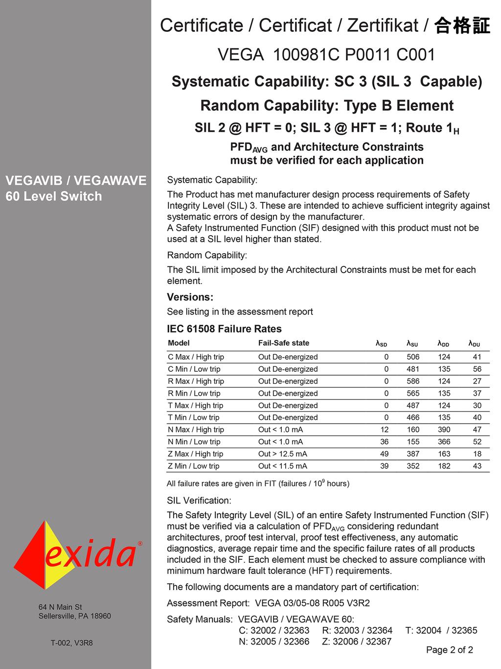
3 1 Functional safety Scope Application area 1.1 General information This safety manual applies to measuring systems consisting of the vibrating level switch VEGAVIB series 60 with integrated electronics module VB60C: VEGAVIB 61, 62, 63 Valid hardware and software versions: Sensor software from Rev Serial number of the electronics > The measuring system can be implemented for level detection of bulk solids (powders and granulates) which meets the special requirements of safety technology. Due to the systematic capability SC3 this is possible up to: SIL2 in single-channel architecture SIL3 in multiple channel architecture Note: With a special factory setting, the measuring system is also suitable for detection of solids in water (see "Operating instructions manual"). SIL conformity Abbreviations, terms Relevant standards The SIL conformity is confirmed by the verification documents in the appendix. SIL HFT SFF PFD avg PFH FMEDA λ sd λ su λ dd λ du Safety Integrity Level Hardware Fault Tolerance Safe Failure Fraction Average Probability of dangerous Failure on Demand Probability of a dangerous Failure per Hour Failure Mode, Effects and Diagnostics Analysis Rate for safe detected failure Rate for safe undetected failure Rate for dangerous detected failure Rate for dangerous undetected failure DC S Diagnostic Coverage of safe failures; DC S = λ sd /(λ sd +λ su ) DC D Diagnostic Coverage of dangerous failures; DC D = λ dd /(λ dd +λ du ) FIT Failure In Time (1 FIT = 1 failure/10 9 h) MTBF MTTF MTTR Mean Time Between Failure Mean Time To Failure Mean Time To Repair Further abbreviations and terms are stated in IEC IEC (also available as DIN EN) 3
4 Functional safety of electrical/electronic/programmable electronic safety-related systems Safety requirements Failure limit values for a safety function, depending on the SIL class (of IEC , 7.6.2) Safety integrity level Low demand mode High demand mode SIL PFD avg PFH < < < < < < < < 10-5 Safety integrity of hardware for safety-related subsystems of type B (IEC , 7.4.3) Safe failure fraction Hardware fault tolerance SFF HFT = 0 HFT = 1 HFT = 2 < 60 % not permitted SIL1 SIL2 60 % < 90 % SIL1 SIL2 SIL3 90 % < 99 % SIL2 SIL3 (SIL4) 99 % SIL3 (SIL4) (SIL4) Safety function Safe state 1.2 Planning The safety function of this measuring system is the identification and signalling of the condition of the vibrating element. A difference is made between the two conditions "covered" and "uncovered". The safe state depends on the mode: Vibrating element in safe state Output circuit in safe state Overflow protection (max. operation) covered currentless Dry run protection (min. operation) uncovered currentless Fault description 4 The safe state of the measuring system is the switched-off status (idle current principle): C electronics: contactless electronic switch open R electronics: relay output deenergised T electronics: transistor output non-conductive A safe failure exists when the measuring system switches to the defined safe state or the fault mode without the process demanding it.
5 If the internal diagnostic system detects a failure, the measuring system goes into fault mode. A dangerous undetected failure exists if the measuring system switches neither to the defined safe state nor to the failure mode when the process requires it. Configuration of the processing unit Low demand mode High demand mode The processing unit must evaluate the output circuit of the measuring system under the conditions of the quiescent current principle. The processing unit must correspond to the SIL level of the measurement chain. If the demand rate is only once a year, then the measuring system can be used as safety-relevant subsystem in "low demand mode" (IEC , ). If the ratio of the internal diagnostics test rate of the measuring system to the demand rate exceeds the value 100, the measuring system can be treated as if it is executing a safety function in the mode with low demand rate (IEC , ). An associated characteristic is the value PFD avg (average Probability of dangerous Failure on Demand). It is dependent on the test interval T Proof between the function tests of the protective function. Number values see chapter "Safety-related characteristics". If the "low demand rate" does not apply, the measuring system should be used as a safety-relevant subsystem in the mode "high demand mode" (IEC , ). The fault tolerance time of the complete system must be higher than the sum of the reaction times or the diagnostics test periods of all components in the safety-related measurement chain. An associated characteristic is the value PFH (failure rate). Number values see chapter "Safety-related characteristics". Assumptions The following assumptions form the basis for the implementation of FMEDA: Failure rates are constant, wear of the mechanical parts is not taken into account Failure rates of external power supplies are not taken into account Multiple errors are not taken into account The average ambient temperature during the operating time is 40 C (104 F) The environmental conditions correspond to an average industrial environment The lifetime of the components is around 8 to 12 years (IEC , , remark 3) The repair time (exchange of the measuring system) after an nondangerous malfunction is eight hours (MTTR = 8 h) The processing unit evaluates the output circuit of the measuring system according to the idle current principle. The scanning interval of a connected control and processing unit is max. 1 hour, in order to react to dangerous, detectable errors 5
6 Existing communication interfaces (e. g. HART, I²C-Bus) are not used for transmission of safety-relevant information General instructions and restrictions Adjustment elements Mounting and installation Operation and interference 6 The measuring system should be used appropriately taking pressure, temperature, density and chemical properties of the medium into account. The user-specific limits must be complied with. The specifications of the operating instructions manual must not be exceeded. Keep in mind when using as dry run protection: Avoid buildup on the vibrating system (probably shorter proof test intervals will be necessary) Fork version: avoid granulate size of the medium > 15 mm (0.6 in) 1.3 Adjustment instructions Since the plant conditions influence the safety of the measuring system, the adjustment elements must be set according to the application: Potentiometer for switching point adaptation DIL switch for mode adjustment The function of the adjustment elements is described in the operating instructions manual. 1.4 Setup Take note of the mounting and installation instructions in the operating instructions manual. In the setup procedure, a check of the safety function by means of an initial filling is recommended. 1.5 Reaction during operation and in case of failure The adjustment elements or device parameters must not be modified during operation. If modifications have to be made during operation, carefully observe the safety functions. Fault signals that may appear are described in the appropriate operating instructions manual. If faults or error messages are detected, the entire measuring system must be shut down and the process held in a safe state by other measures. The exchange of the electronics is simple and described in the operating instructions manual. Note the instructions for parameter adjustment and setup. If due to a detected failure the electronics or the complete sensor is exchanged, the manufacturer must be informed (incl. a fault description).
7 Reason Implementation Basics 1.6 Recurring function test The recurring function test is testing the safety function and to find out possible undetected, dangerous failuress. The functional capability of the measuring system has to be tested in adequate time intervals. It is up to the user's responsibility to selct the kind of testing. The time intervals are subject to the PFD avg -value according to the chart and diagram in section "Safety-relevant characteristics". With high demand rate, a recurring function test is not requested in IEC The functional efficiency of the measuring system is demonstrated by the frequent use of the system. In double channel architectures it is a good idea to verify the effect of the redundancy through recurring function tests at appropriate intervals. Please carry out the test in such a way, that the correct safety function in combination with all components is granted. This is granted by the control of the response height during a filling process. If a filling up to the response height is not practicable, the measuring system has to be responded by an appropriate simulation of the level or the physical measuring effect. The methods and procedures used during the tests must be stated and their suitability must be specified. The tests must be documented. If the function test proves negative, the entire measuring system must be switched out of service and the process held in a safe state by means of other measures. In a multiple channel architecture this applies separately to each channel. 1.7 Safety-related characteristics The failure rates of the electronics, the mechanical parts of the transmitter as well as the process fitting are determined by an FMEDA according to IEC The calculations are based on component failure rates according to SN All values refer to an average ambient temperature during the operating time of 40 C (104 F). For a higher average temperature of 60 C (140 F), the failure rates should be multiplied by a factor of 2.5. A similar factor applies if frequent temperature fluctuations are expected. The calculations are also based on the specifications stated in chapter "Planning". Service life Failure rates After 8 to 12 years, the failure rates of the electronic components will increase, whereby the derived PFD and PFH values will deteriorate (IEC , , note 3). Overflow protection (max. operation) λ sd 0 FIT 0 FIT λ su 506 FIT 481 FIT λ dd 124 FIT 135 FIT Dry run protection (min. operation) 7
8 Overflow protection (max. operation) λ du 41 FIT 56 FIT DC S 0 % 0 % DC D 75 % 71 % Dry run protection (min. operation) MTBF = MTTF + MTTR 1.45 x 10 6 h 1.45 x 10 6 h Fault reaction time Diagnosis test period < 100 sec. Specific characteristics Single channel architecture SIL SIL2 HFT 0 Instrument type Type B Overflow protection (max. operation) SFF 94 % 92 % PFD avg T Proof = 1 year T Proof = 5 years T Proof = 10 years < x 10-2 < x 10-2 < x 10-2 Dry run protection (min. operation) < x 10-2 < x 10-2 < x 10-2 PFH < x 10-6 /h < x 10-6 /h Time-dependent process of PFD avg The chronological sequence of PFD avg is nearly linear to the operating time over a period up to 10 years. The above values apply only to the T Proof interval after which a recurring function test must be carried out. 4 PFD avg T Proof 8 Fig. 1: Chronological sequence of PFD avg (figures see above charts) 1 PFD avg = 0 2 PFD avg after 1 year 3 PFD avg after 5 years 4 PFD avg after 10 years
9 Multiple channel architecture Specific characteristics If the measuring system is used in a multiple channel architecture, the safety-relevant characteristics of the selected structure of the meas. chain must be calculated specifically for the selected application according to the above failure rates. A suitable Common Cause Factor must be taken into account. 9

10 2 Supplement 2 Supplement 10
11 2 Supplement 11
12 Printing date: All statements concerning scope of delivery, application, practical use and operating conditions of the sensors and processing systems correspond to the information available at the time of printing. Subject to change without prior notice VEGA Grieshaber KG, Schiltach/Germany 2018 VEGA Grieshaber KG Am Hohenstein Schiltach Germany Phone Fax
Safety Manual VEGAVIB series 60
 Safety Manual VEGAVIB series 60 NAMUR Document ID: 32005 Contents Contents 1 Functional safety... 3 1.1 General information... 3 1.2 Planning... 4 1.3 Adjustment instructions... 6 1.4 Setup... 6 1.5 Reaction
Safety Manual OPTISWITCH series relay (DPDT)
") Safety Manual OPTISWITCH series 5000 - relay (DPDT) 1 Content Content 1 Functional safety 1.1 In general................................ 3 1.2 Planning................................. 5 1.3 Adjustment
Safety Manual OPTISWITCH series 5000 - relay (DPDT) 1 Content Content 1 Functional safety 1.1 In general................................ 3 1.2 Planning................................. 5 1.3 Adjustment
Safety Manual. Process pressure transmitter IPT-1* 4 20 ma/hart. Process pressure transmitter IPT-1*
 Safety Manual Process pressure transmitter IPT-1* 4 20 ma/hart Process pressure transmitter IPT-1* Contents Contents 1 Functional safety 1.1 General information... 3 1.2 Planning... 4 1.3 Instrument parameter
Safety Manual VEGASWING 61, 63. NAMUR With SIL qualification. Document ID: 52084
 Safety Manual VEGASWING 61, 63 NAMUR With SIL qualification Document ID: 52084 Contents Contents 1 Document language 2 Scope 2.1 Instrument version... 4 2.2 Area of application... 4 2.3 SIL conformity...
Vibrating Switches SITRANS LVL 200S, LVL 200E. Safety Manual. NAMUR With SIL qualification
 Vibrating Switches SITRANS LVL 200S, LVL 200E NAMUR With SIL qualification Safety Manual Contents 1 Document language 2 Scope 2.1 Instrument version... 4 2.2 Area of application... 4 2.3 SIL conformity...
Special Documentation Proline Promass 80, 83
 SD00077D/06/EN/14.14 71272498 Products Solutions Services Special Documentation Proline Promass 80, 83 Functional safety manual Coriolis mass flow measuring system with 4 20 ma output signal Application
Failure Modes, Effects and Diagnostic Analysis
 Failure Modes, Effects and Diagnostic Analysis Project: Solenoid Drivers KFD2-SL2-(Ex)1.LK.vvcc KFD2-SL2-(Ex)*(.B).vvcc Customer: Pepperl+Fuchs GmbH Mannheim Germany Contract No.: P+F 06/09-23 Report No.:
Failure Modes, Effects and Diagnostic Analysis
 Failure Modes, Effects and Diagnostic Analysis Project: Isolating repeater 9164 Customer: R. STAHL Schaltgeräte GmbH Waldenburg Germany Contract No.: STAHL 16/08-032 Report No.: STAHL 16/08-032 R032 Version
Failure Modes, Effects and Diagnostic Analysis
 Failure Modes, Effects and Diagnostic Analysis Project: Temperature transmitter PR5337 / PR6337 / PR7501 with 4..20 ma output Customer: PR electronics A/S Rønde Denmark Contract No.: PR electronics A/S
FP15 Interface Valve. SIL Safety Manual. SIL SM.018 Rev 1. Compiled By : G. Elliott, Date: 30/10/2017. Innovative and Reliable Valve & Pump Solutions
 SIL SM.018 Rev 1 FP15 Interface Valve Compiled By : G. Elliott, Date: 30/10/2017 FP15/L1 FP15/H1 Contents Terminology Definitions......3 Acronyms & Abbreviations...4 1. Introduction...5 1.1 Scope.. 5 1.2
SIL Safety Manual. ULTRAMAT 6 Gas Analyzer for the Determination of IR-Absorbing Gases. Supplement to instruction manual ULTRAMAT 6 and OXYMAT 6
 ULTRAMAT 6 Gas Analyzer for the Determination of IR-Absorbing Gases SIL Safety Manual Supplement to instruction manual ULTRAMAT 6 and OXYMAT 6 ULTRAMAT 6F 7MB2111, 7MB2117, 7MB2112, 7MB2118 ULTRAMAT 6E
Eutectic Plug Valve. SIL Safety Manual. SIL SM.015 Rev 0. Compiled By : G. Elliott, Date: 19/10/2016. Innovative and Reliable Valve & Pump Solutions
 SIL SM.015 Rev 0 Eutectic Plug Valve Compiled By : G. Elliott, Date: 19/10/2016 Contents Terminology Definitions......3 Acronyms & Abbreviations...4 1. Introduction..5 1.1 Scope 5 1.2 Relevant Standards
Failure Modes, Effects and Diagnostic Analysis
 Failure Modes, Effects and Diagnostic Analysis Project: Solenoid Valves SNMF 532 024 ** ** and SMF 52 024 ** ** Customer: ACG Automation Center Germany GmbH & Co. KG Tettnang Germany Contract No.: ACG
Hydraulic (Subsea) Shuttle Valves
 Shuttle Valves") SIL SM.009 0 Hydraulic (Subsea) Shuttle Valves Compiled By : G. Elliott, Date: 11/3/2014 Contents Terminology Definitions......3 Acronyms & Abbreviations..4 1. Introduction 5 1.1 Scope 5 1.2 Relevant Standards
SIL SM.009 0 Hydraulic (Subsea) Shuttle Valves Compiled By : G. Elliott, Date: 11/3/2014 Contents Terminology Definitions......3 Acronyms & Abbreviations..4 1. Introduction 5 1.1 Scope 5 1.2 Relevant Standards
Solenoid Valves For Gas Service FP02G & FP05G
 SIL Safety Manual SM.0002 Rev 02 Solenoid Valves For Gas Service FP02G & FP05G Compiled By : G. Elliott, Date: 31/10/2017 Reviewed By : Peter Kyrycz Date: 31/10/2017 Contents Terminology Definitions......3
Accelerometer mod. TA18-S. SIL Safety Report
 Accelerometer mod. TA18-S SIL Safety Report SIL005/11 rev.1 of 03.02.2011 Page 1 of 7 1. Field of use The transducers are made to monitoring vibrations in systems that must meet particular technical safety
Pneumatic QEV. SIL Safety Manual SIL SM Compiled By : G. Elliott, Date: 8/19/2015. Innovative and Reliable Valve & Pump Solutions
 SIL SM.0010 1 Pneumatic QEV Compiled By : G. Elliott, Date: 8/19/2015 Contents Terminology Definitions......3 Acronyms & Abbreviations..4 1. Introduction 5 1.1 Scope 5 1.2 Relevant Standards 5 1.3 Other
Bespoke Hydraulic Manifold Assembly
 SIL SM.0003 1 Bespoke Hydraulic Manifold Assembly Compiled By : G. Elliott, Date: 12/17/2015 Contents Terminology Definitions......3 Acronyms & Abbreviations..4 1. Introduction 5 1.1 Scope 5 1.2 Relevant
Failure Modes, Effects and Diagnostic Analysis. Rosemount Inc. Chanhassen, MN USA
 Failure Modes, Effects and Diagnostic Analysis Project: 3095MV Mass Flow Transmitter Customer: Rosemount Inc. Chanhassen, MN USA Contract No.: Q04/04-09 Report No.: Ros 04/04-09 R001 Version V1, Revision
Failure Modes, Effects and Diagnostic Analysis
 Failure Modes, Effects and Diagnostic Analysis Project: Surge Protective Devices D9324S Customer: G.M. International s.r.l Villasanta Italy Contract No.: GM 16/02-055 Report No.: GM 16/02-055 R005 Version
Ultima. X Series Gas Monitor
 Ultima X Series Gas Monitor Safety Manual SIL 2 Certified " The Ultima X Series Gas Monitor is qualified as an SIL 2 device under IEC 61508 and must be installed, used, and maintained in accordance with
Neles ValvGuard VG9000H Rev 2.0. Safety Manual
 Neles ValvGuard VG9000H Rev 2.0 Safety Manual 10SM VG9000H en 11/2016 2 Neles ValvGuard VG9000H Rev 2.0 Safety Manual Table of Contents 1 General information...3 1.1 Purpose of the document... 3 1.2 Description
H250 M9 Supplementary instructions
 H250 M9 Supplementary instructions Variable area flowmeter Safety manual acc. to IEC 61508:2010 KROHNE CONTENTS H250 M9 1 Introduction 3 1.1 Fields of application... 3 1.2 User benefits... 3 1.3 Relevant
Rosemount 2130 Level Switch
 Rosemount 2130 Level Switch Functional Safety Manual Manual Supplement Reference Manual Contents Contents 1Section 1: Introduction 1.1 Scope and purpose of the safety manual.............................................
Solenoid Valves used in Safety Instrumented Systems
 I&M V9629R1 Solenoid Valves used in Safety Instrumented Systems Operating Manual in accordance with IEC 61508 ASCO Valves Page 1 of 7 Table of Contents 1 Introduction...3 1.1 Terms and Abbreviations...3
What safety level can be reached when combining a contactor with a circuitbreaker for fail-safe switching?
 FAQ 01/2015 What safety level can be reached when combining a contactor with a circuitbreaker for fail-safe switching? SIRIUS Safety Integrated http://support.automation.siemens.com/ww/view/en/40349715
Failure Modes, Effects and Diagnostic Analysis
 Failure Modes, Effects and Diagnostic Analysis Project: Ground Monitoring Device 71**/5, 81**/5, 82**/5 Company: R. STAHL Schaltgeräte GmbH Waldenburg Germany Contract No.: STAHL 11/07-089 Report No.:
SPR - Pneumatic Spool Valve
 SIL SM.008 Rev 7 SPR - Pneumatic Spool Valve Compiled By : G. Elliott, Date: 31/08/17 Contents Terminology Definitions:... 3 Acronyms & Abbreviations:... 4 1.0 Introduction... 5 1.1 Purpose & Scope...
Section 1: Multiple Choice
 CFSP Process Applications Section 1: Multiple Choice EXAMPLE Candidate Exam Number (No Name): Please write down your name in the above provided space. Only one answer is correct. Please circle only the
Failure Modes, Effects and Diagnostic Analysis
 Failure Modes, Effects and Diagnostic Analysis Project: Contact elements Type 8082 and Type 8208 with or without 8602 actuator Customer: R. STAHL Schaltgeräte GmbH Waldenburg Germany Contract No.: Stahl
Failure Modes, Effects and Diagnostic Analysis. Rosemount Inc. Chanhassen, Minnesota USA
 Failure Modes, Effects and Diagnostic Analysis Project: 3051C Pressure Transmitter Customer: Rosemount Inc. Chanhassen, Minnesota USA Contract No.: Ros 03/10-11 Report No.: Ros 03/10-11 R001 Version V1,
Failure Modes, Effects and Diagnostic Analysis
 Failure Modes, Effects and Diagnostic Analysis Project: 3051S SIS Pressure Transmitter, with Safety Feature Board, Software Revision 3.0 Customer: Rosemount Inc. Chanhassen, MN USA Contract No.: Ros 02/11-07
Failure Modes, Effects and Diagnostic Analysis
 Failure Modes, Effects and Diagnostic Analysis Project: Variable area flow meter RAMC Customer: Rota Yokogawa GmbH & Co. KG Wehr Germany Contract No.: Rota Yokogawa 05/04-20 Report No.: Rota Yokogawa 05/04-20
Product information Vibrating
 Product information Level detection in bulk solids VEGAVIB 61 VEGAVIB 62 VEGAVIB 63 VEGAWAVE 61 VEGAWAVE 62 VEGAWAVE 63 Document ID: 29438 Contents Contents 1 Description of the measuring principle...
This manual provides necessary requirements for meeting the IEC or IEC functional safety standards.
 Instruction Manual Supplement Safety manual for Fisher Vee-Ball Series Purpose This safety manual provides information necessary to design, install, verify and maintain a Safety Instrumented Function (SIF)
Commissioning and safety manual
 Commissioning and safety manual CNL35L DNL35L SIL2 LOREME 12, rue des Potiers d'etain Actipole BORNY - B.P. 35014-57071 METZ CEDEX 3 Phone 03.87.76.32.51 - Telefax 03.87.76.32.52 Contact: Commercial@Loreme.fr
Neles trunnion mounted ball valve Series D Rev. 2. Safety Manual
 Neles trunnion mounted ball valve Series D Rev. 2 Safety Manual 10SM D en 1/2017 2 Neles trunnion mounted ball valve, Series D Table of Contents 1 Introduction...3 2 Structure of the D series trunnion
Failure Modes, Effects and Diagnostic Analysis
 Failure Modes, Effects and Diagnostic Analysis Project: Digital Output Module Valve DOMV 9478/22-08-51 Company: R. STAHL Schaltgeräte GmbH Waldenburg Germany Contract No.: STAHL 11/01-104 Report No.: STAHL
Functional safety. Functional safety of Programmable systems, devices & components: Requirements from global & national standards
 Functional safety Functional safety of Programmable systems, devices & components: Requirements from global & national standards Matthias R. Heinze Vice President Engineering TUV Rheinland of N.A. Email
Safety manual for Fisher GX Control Valve and Actuator
 Instruction Manual Supplement GX Valve and Actuator Safety manual for Fisher GX Control Valve and Actuator Purpose This safety manual provides information necessary to design, install, verify and maintain
Reliability of Safety-Critical Systems Chapter 3. Failures and Failure Analysis
 Reliability of Safety-Critical Systems Chapter 3. Failures and Failure Analysis Mary Ann Lundteigen and Marvin Rausand mary.a.lundteigen@ntnu.no RAMS Group Department of Production and Quality Engineering
RESILIENT SEATED BUTTERFLY VALVES FUNCTIONAL SAFETY MANUAL
 Per IEC 61508 and IEC 61511 Standards BRAY.COM Table of Contents 1.0 Introduction.................................................... 1 1.1 Terms and Abbreviations...........................................
Special Documentation Liquiphant M/S with electronic insert FEL56 + Nivotester FTL325N
 [Ex ia] CH1 CH1 [Ex ia] CH1 CH2 CH3 CH2 CH3 SD01521F/00/EN/02.16 71329742 Products Solutions Services Special Documentation Liquiphant M/S with electronic insert FEL56 + Nivotester FTL325N Functional Safety
DeZURIK. KGC Cast Knife Gate Valve. Safety Manual
 KGC Cast Knife Gate Valve Safety Manual Manual D11036 August 29, 2014 Table of Contents 1 Introduction... 3 1.1 Terms... 3 1.2 Abbreviations... 4 1.3 Product Support... 4 1.4 Related Literature... 4 1.5
DeZURIK. KSV Knife Gate Valve. Safety Manual
 KSV Knife Gate Valve Safety Manual Manual D11035 August 29, 2014 Table of Contents 1 Introduction... 3 1.1 Terms... 3 1.2 Abbreviations... 4 1.3 Product Support... 4 1.4 Related Literature... 4 1.5 Reference
Transmitter mod. TR-A/V. SIL Safety Report
 Transmitter mod. TR-A/V SIL Safety Report SIL003/09 rev.1 del 09.03.2009 Pagina 1 di 7 1. Employ field The transmitters are dedicated to the vibration monitoring in plants where particular safety requirements
DeZURIK Double Block & Bleed (DBB) Knife Gate Valve Safety Manual
 Knife Gate Valve Safety Manual") Double Block & Bleed (DBB) Knife Gate Valve Safety Manual Manual D11044 September, 2015 Table of Contents 1 Introduction... 3 1.1 Terms... 3 1.2 Abbreviations... 4 1.3 Product Support... 4 1.4 Related
Double Block & Bleed (DBB) Knife Gate Valve Safety Manual Manual D11044 September, 2015 Table of Contents 1 Introduction... 3 1.1 Terms... 3 1.2 Abbreviations... 4 1.3 Product Support... 4 1.4 Related
YT-3300 / 3301 / 3302 / 3303 / 3350 / 3400 /
 Smart positioner YT-3300 / 3301 / 3302 / 3303 / 3350 / 3400 / 3410 / 3450 Series SIL Safety Instruction. Supplement to product manual July. 2015 YTC Ver 1.06 1 Table of contents 1 Introduction... 3 1.1
Continuous Gas Analysis. ULTRAMAT 6, OXYMAT 6 Safety Manual. Introduction 1. General description of functional safety 2
 Introduction 1 General description of functional safety 2 Continuous Gas Analysis ULTRAMAT 6, OXYMAT 6 Device-specific safety instructions 3 List of abbreviations A Operating Instructions Supplement to
Rosemount 2120 Level Switch
 Rosemount 2120 Level Switch Functional Safety Manual Manual Supplement Manual Supplement Contents Contents 1Section 1: Introduction 1.1 Scope and purpose of the safety manual.............................................
Functional Safety SIL Safety Instrumented Systems in the Process Industry
 Products Solutions Services Functional Safety SIL Safety Instrumented Systems in the Process Industry BASF - Press Photo 2 section Foreword rubric 3 Foreword has come into focus since the publication of
Product information. Capacitive. Level detection in liquid VEGACAP 62 VEGACAP 63 VEGACAP 64 VEGACAP 66 VEGACAP 69. Document ID: 29983
 Product information Level detection in liquid VEGACAP 62 VEGACAP 63 VEGACAP 64 VEGACAP 66 VEGACAP 69 Document ID: 29983 Contents Contents 1 Description of the measuring principle... 3 2 Type overview...
Section 1: Multiple Choice Explained EXAMPLE
 CFSP Process Applications Section 1: Multiple Choice Explained EXAMPLE Candidate Exam Number (No Name): Please write down your name in the above provided space. Only one answer is correct. Please circle
Special Documentation Liquiphant M/S with electronic insert FEL57 + Nivotester FTL325P
 [Ex ia] CH1 CH1 [Ex ia] CH1 CH2 CH3 CH2 CH3 SD01508F/00/EN/02.16 71329740 Products Solutions Services Special Documentation Liquiphant M/S with electronic insert FEL57 + Nivotester FTL325P Functional Safety
Failure Modes, Effects and Diagnostic Analysis
 Failure Modes, Effects and Diagnostic Analysis Project: Abc. X Series Ball Valve Company: Abc. Inc. Sellersville, PA USA Contract Number: Q11/12-345 Report No.: Abc 11/12-345 R001 Version V1, Revision
TRI LOK SAFETY MANUAL TRI LOK TRIPLE OFFSET BUTTERFLY VALVE. The High Performance Company
 TRI LOK TRI LOK TRIPLE OFFSET BUTTERFLY VALVE SAFETY MANUAL The High Performance Company Table of Contents 1.0 Introduction...1 1.1 Terms and Abbreviations... 1 1.2 Acronyms... 1 1.3 Product Support...
Jamesbury Pneumatic Rack and Pinion Actuator
 Jamesbury Pneumatic Rack and Pinion Actuator Valv-Powr Series VPVL Rev. 3.0 Safety Manual 10SM VPVL en 5/2017 2 Jamesbury Pneumatic Rack and Pinion Actuator, Valv-Powr Series VPVL, Rev 3.0, Safety Manual
Achieving Compliance in Hardware Fault Tolerance
 Mirek Generowicz FS Senior Expert (TÜV Rheinland #183/12) Engineering Manager, I&E Systems Pty Ltd Abstract The functional safety standards ISA S84/IEC 61511 (1 st Edition, 2003) and IEC 61508 both set
Failure Modes, Effects and Diagnostic Analysis
 Failure Modes, Effects and Diagnostic Analysis Project: Primary Elements Company: Rosemount Inc. (an Emerson Process Management company) Chanhassen, MN USA Contract Number: Q13/04-008 Report No.: ROS 13/04-008
COMPLIANCE with IEC EN and IEC EN 61511
 COMPLIANCE with IEC EN 61508 and IEC EN 61511 Certificate No.: C- IS-260811 01 CERTIFICATE OWNER: ORION S.p.A. VIA CABOTO, 8 I-34148 TRIESTE (Italy) WE HEREWITH CONFIRM THAT THE ANALYSIS DEVELOPED BY ORION;
EL-O-Matic E and P Series Pneumatic Actuator SIL Safety Manual
 SIL Safety Manual DOC.SILM.EEP.EN Rev. 0 April 2017 EL-O-Matic E and P Series Pneumatic Actuator SIL Safety Manual schaal 1:1 EL Matic TM EL-O-Matic E and P Series DOC.SILM.EEP.EN Rev. 0 Table of Contents
Operating Instructions. Ball valve fitting according to ZB For pressure transmitter VEGABAR 82. Document ID: 50027
 Operating Instructions Ball valve fitting according to ZB 2553 For pressure transmitter VEGABAR 82 Document ID: 50027 Contents Contents 1 About this document 1.1 Function... 3 1.2 Target group... 3 1.3
New Thinking in Control Reliability
 Doug Nix, A.Sc.T. Compliance InSight Consulting Inc. New Thinking in Control Reliability Or Your Next Big Headache www.machinerysafety101.com (519) 729-5704 Control Reliability Burning Questions from the
High performance disc valves Series Type BA, BK, BW, BM, BN, BO, BE, BH Rev Safety Manual
 High performance disc valves Series Type BA, BK, BW, BM, BN, BO, BE, BH Rev. 2.0 Safety Manual 10SM B Disc en 4/2018 2 High performance disc valves Series, Type BA, BK, BW, BM, BN, BO, BE, BH, Rev. 2.0
High Integrity Pressure Protection Systems HIPPS
 High Integrity Pressure Protection Systems HIPPS HIPPS > High Integrity Pressure Protection Systems WHAT IS A HIPPS The High Integrity Pressure Protection Systems (HIPPS) is a mechanical and electrical
PL estimation acc. to EN ISO
 PL estimation acc. to EN ISO 3849- Example calculation for an application MAC Safety / Armin Wenigenrath, January 2007 Select the suitable standard for your application Reminder: The standards and the
Failure Modes, Effects, and Diagnostic Analysis of a Safety Device
 Elias Mabook Failure Modes, Effects, and Diagnostic Analysis of a Safety Device Helsinki Metropolia University of Applied Sciences Bachelor of Engineering Degree Programme in Electronics Bachelor s Thesis
The Key Variables Needed for PFDavg Calculation
 Iwan van Beurden, CFSE Dr. William M. Goble, CFSE exida Sellersville, PA 18960, USA wgoble@exida.com July 2015 Update 1.2 September 2016 Abstract In performance based functional safety standards, safety
PROCESS AUTOMATION SIL. Manual Safety Integrity Level. Edition 2005 IEC 61508/61511
 PROCESS AUTOMATION Manual Safety Integrity Level SIL Edition 2005 IEC 61508/61511 With regard to the supply of products, the current issue of the following document is applicable: The General Terms of
Understanding safety life cycles
 Understanding safety life cycles IEC/EN 61508 is the basis for the specification, design, and operation of safety instrumented systems (SIS) Fast Forward: IEC/EN 61508 standards need to be implemented
Failure Modes, Effects and Diagnostic Analysis
 Failure Modes, Effects and Diagnostic Analysis Project: Emerson s Rosemount 2051 Pressure Transmitter with 4-20mA HART Device Label SW 1.0.0-1.4.x Company: Rosemount Inc. Shakopee, MN USA Contract No.:
Transducer mod. T-NC/8-API. SIL Safety Report
 CEMB S.p.a. Transducer mod. T-NC/8-API SIL Safety Report SIL006/11 rev.0 dated 03.03.2011 Page 1 di 7 1. Employ field The transducers can measure the static or dynamic distance in plants which need to
Service & Support. Questions and Answers about the Proof Test Interval. Proof Test According to IEC FAQ August Answers for industry.
 Cover sheet Questions and Answers about the Proof Test Interval Proof Test According to IEC 62061 FAQ August 2012 Service & Support Answers for industry. Contents This entry originates from the Siemens
L&T Valves Limited SAFETY INTEGRITY LEVEL (SIL) VERIFICATION FOR HIGH INTEGRITY PRESSURE PROTECTION SYSTEM (HIPPS) Report No.
 VERIFICATION FOR HIGH INTEGRITY PRESSURE PROTECTION SYSTEM (HIPPS) Report No.") L&T Valves Limited TAMIL NADU SAFETY INTEGRITY LEVEL (SIL) VERIFICATION FOR HIGH INTEGRITY PRESSURE PROTECTION SYSTEM (HIPPS) MAY 2016 Report No. 8113245702-100-01 Submitted to L&T Valves Ltd. Report by
L&T Valves Limited TAMIL NADU SAFETY INTEGRITY LEVEL (SIL) VERIFICATION FOR HIGH INTEGRITY PRESSURE PROTECTION SYSTEM (HIPPS) MAY 2016 Report No. 8113245702-100-01 Submitted to L&T Valves Ltd. Report by
YT-300 / 305 / 310 / 315 / 320 / 325 Series
 Volume Booster YT-300 / 305 / 310 / 315 / 320 / 325 Series SIL Safety Instruction. Supplement to product manual Apr. 2016 YTC Ver. 2.01 1 Table of contents 1 Introduction... 3 1.1 Purpose of this document...
Reliability of Safety-Critical Systems Chapter 4. Testing and Maintenance
 Reliability of Safety-Critical Systems Chapter 4. Testing and Maintenance Mary Ann Lundteigen and Marvin Rausand mary.a.lundteigen@ntnu.no RAMS Group Department of Production and Quality Engineering NTNU
Session: 14 SIL or PL? What is the difference?
 Session: 14 SIL or PL? What is the difference? Stewart Robinson MIET MInstMC Consultant Engineer, Pilz Automation Technology UK Ltd. EN ISO 13849-1 and EN 6061 Having two different standards for safety
Applications & Tools. Evaluation of the selection of a safetyrelated mode using non-safety-related components
 Cover sheet Evaluation of the selection of a safetyrelated mode using non-safety-related components SINUMERIK 840D sl SINUMERIK Safety Integrated Application description February 2015 Applications & Tools
Product information. Capacitive. Level detection with bulk solids VEGACAP 62 VEGACAP 65 VEGACAP 66 VEGACAP 67. Document ID: 29982
 Product information Level detection with bulk solids VEGACAP 62 VEGACAP 65 VEGACAP 66 VEGACAP 67 Document ID: 29982 Contents Contents 1 Description of the measuring principle... 3 2 Type overview... 5
THE IMPROVEMENT OF SIL CALCULATION METHODOLOGY. Jinhyung Park 1 II. THE SIL CALCULATION METHODOLOGY ON IEC61508 AND SOME ARGUMENT
 THE IMPROVEMENT OF SIL CALCULATION METHODOLOGY Jinhyung Park 1 1 Yokogawa Electric Korea: 21, Seonyu-ro45-gil Yeongdeungpo-gu, Seoul, 07209, Jinhyung.park@kr.yokogawa.com Safety Integrity Level (SIL) is
Competence in Functional Safety
 MANUAL Competence in Functional Safety Safety-instrumented system Instrumentation Automation SMART IN FLOW CONTROL. SAMSON AIR TORQUE CERA SYSTEM KT-ELEKTRONIK LEUSCH PFEIFFER RINGO SAMSOMATIC STARLINE
SIL Safety Manual for Fisherr ED, ES, ET, EZ, HP, or HPA Valves with 657 / 667 Actuator
 SIL Safety Manual ED, ES, ET, EZ, HP, HPA Valves w/ 657/667 Actuator SIL Safety Manual for Fisherr ED, ES, ET, EZ, HP, or HPA Valves with 657 / 667 Actuator Purpose This safety manual provides information
DSB, DSF: Pressure monitors and pressure switches
 roduct data sheet 23.760 DSB, DSF: ressure monitors and pressure switches How energy efficiency is improved Control and monitoring according to needs and with no auxiliary energy Features For regulating
Every things under control High-Integrity Pressure Protection System (HIPPS)
") Every things under control www.adico.co info@adico.co Table Of Contents 1. Introduction... 2 2. Standards... 3 3. HIPPS vs Emergency Shut Down... 4 4. Safety Requirement Specification... 4 5. Device Integrity
Every things under control www.adico.co info@adico.co Table Of Contents 1. Introduction... 2 2. Standards... 3 3. HIPPS vs Emergency Shut Down... 4 4. Safety Requirement Specification... 4 5. Device Integrity
SIL explained. Understanding the use of valve actuators in SIL rated safety instrumented systems ACTUATION
 SIL explained Understanding the use of valve actuators in SIL rated safety instrumented systems The requirement for Safety Integrity Level (SIL) equipment can be complicated and confusing. In this document,
Valve Communication Solutions. Safety instrumented systems
 Safety instrumented systems Safety Instrumented System (SIS) is implemented as part of a risk reduction strategy. The primary focus is to prevent catastrophic accidents resulting from abnormal operation.
CHANGE HISTORY DISTRIBUTION LIST
 Issue Date of Issue CR/DR Numbers CHANGE HISTORY No. of Pages Draft A Aug 2011 N/A 28 Draft Issue Pages Changed and Reasons for Change Sept 2011 N/A 28 Formal issue with client comments from draft issue
Understanding the How, Why, and What of a Safety Integrity Level (SIL)
") Understanding the How, Why, and What of a Safety Integrity Level (SIL) Audio is provided via internet. Please enable your speaker (in all places) and mute your microphone. Understanding the How, Why, and
Understanding the How, Why, and What of a Safety Integrity Level (SIL) Audio is provided via internet. Please enable your speaker (in all places) and mute your microphone. Understanding the How, Why, and
Technical Data Sheet MF010-O-LC
 Technical Data Sheet MF010-O-LC - 1 - 1. Properties The oxygen measuring system MF010-O-LC determines the oxygen content in gas mixtures up to a temperature of 250 C. It is particularly suitable for the
Safety-critical systems: Basic definitions
 Safety-critical systems: Basic definitions Ákos Horváth Based on István Majzik s slides Dept. of Measurement and Information Systems Budapest University of Technology and Economics Department of Measurement
Supplementary instructions. Rod and cable components. for VEGAFLEX series 80. Document ID: 44968
 Supplementary instructions Rod and cable components for VEGAFEX series 80 Document ID: 44968 Contents Contents 1 Product description 1.1 Extensions... 3 2 Mounting 2.1 General instructions... 6 2.2 Rod
Level detection in bulk solids. Vibration VEGAVIB VEGAWAVE Product Information
 Level detection in bulk solids Vibration VEGAVIB 61-63 VEGAWAVE 61-63 Product Information Contents Contents 1 Description of the measuring principle...........................................................
Operating instructions Capacitive sensors KG AC (M18) / / 2010
 / / 2010") Operating instructions Capacitive sensors KG AC (M18) UK 704923 / 00 09 / 2010 Contents 1 Preliminary note 3 2 Safety instructions 3 3 Functions and features 3 3.1 Application examples 4 4 Installation
Operating instructions Capacitive sensors KG AC (M18) UK 704923 / 00 09 / 2010 Contents 1 Preliminary note 3 2 Safety instructions 3 3 Functions and features 3 3.1 Application examples 4 4 Installation
Operating instructions Safety Rope Emergency Stop Switches ZB0052 / ZB0053 ZB0072 / ZB0073
 Operating instructions Safety Rope Emergency Stop Switches UK ZB0052 / ZB0053 ZB0072 / ZB0073 7390878 / 02 03 / 2011 Contents 1 Safety instructions...3 2 Installation / set-up...4 2.1 Applications...4
Session One: A Practical Approach to Managing Safety Critical Equipment and Systems in Process Plants
 Session One: A Practical Approach to Managing Safety Critical Equipment and Systems in Process Plants Tahir Rafique Lead Electrical and Instruments Engineer: Qenos Botany Site Douglas Lloyd Senior Electrical
DSL, DSH: Specially designed pressure limiter
 Product data sheet 11.1 23.770 DSL, DSH: Specially designed pressure limiter How energy efficiency is improved Control and monitoring according to needs and with no auxiliary energy. Features Switching
Supplementary Operator s Manual 42/24-14 EN Rev. 3
 Advance Optima Continuous Gas Analyzers AO2000 Series with Uras26, Magnos206, Caldos25, Caldos27 Designed per Category 3G for Measurement of Flammable Gases ( Safety Concept ) and Non-flammable Gases Supplementary
Operating instructions Capacitive sensor KIA (M30) / / 2010
 / / 2010") Operating instructions Capacitive sensor KIA (M30) UK 704182 / 03 07 / 2010 Contents 1 Preliminary note 3 2 Safety instructions 3 3 Functions and features 3 3.1 Application examples 4 4 Installation 4
Operating instructions Capacitive sensor KIA (M30) UK 704182 / 03 07 / 2010 Contents 1 Preliminary note 3 2 Safety instructions 3 3 Functions and features 3 3.1 Application examples 4 4 Installation 4
model for functional safety of
 Application of Weibull reliability model for functional safety of electro-hydraulic system 1 When the safety of the machinery users relies on a reliable function of the control system, than a safety function
Hygienic Instruction. EHEDG, Installation and Cleaning Instructions. VEGASWING SG51, SWING61, SWING63 Hygienic process fittings. Document ID: 35487
 Hygienic Instruction EHEDG, Installation and Cleaning Instructions VEGASWING SG51, SWING61, SWING63 Hygienic process fittings Document ID: 35487 Contents Contents 1 About this document... 3 1.1 Function...