Granland 76-82, N-3045 Drammen (NO).
|
|
|
- Gyles Hall
- 5 years ago
- Views:
Transcription
1 (12) INTERNATIONAL APPLICATION PUBLISHED UNDER THE PATENT COOPERATION TREATY (PCT) (19) World Intellectual Property Organization International Bureau (10) International Publication Number (43) International Publication Date WO 2013/ Al 31 October 2013 ( ) P O P C T (51) International Patent Classification: (81) Designated States (unless otherwise indicated, for every E02B 15/04 ( ) B63B 35/32 ( ) kind of national protection available): AE, AG, AL, AM, AO, AT, AU, AZ, BA, BB, BG, BH, BN, BR, BW, BY, (21) International Application Number: BZ, CA, CH, CL, CN, CO, CR, CU, CZ, DE, DK, DM, PCT/NO20 13/ DO, DZ, EC, EE, EG, ES, FI, GB, GD, GE, GH, GM, GT, (22) International Filing Date: HN, HR, HU, ID, IL, IN, IS, JP, KE, KG, KM, KN, KP, 26 April 2013 ( ) KR, KZ, LA, LC, LK, LR, LS, LT, LU, LY, MA, MD, (25) Filing Language: English ME, MG, MK, MN, MW, MX, MY, MZ, NA, NG, NI, NO, NZ, OM, PA, PE, PG, PH, PL, PT, QA, RO, RS, RU, (26) Publication Language: English RW, SC, SD, SE, SG, SK, SL, SM, ST, SV, SY, TH, TJ, TM, TN, TR, TT, TZ, UA, UG, US, UZ, VC, VN, ZA, (30) Priority Data: ZM, ZW April 2012 ( ) NO (84) Designated States (unless otherwise indicated, for every (71) Applicant: JASON ENGINEERING AS [NO/NO]; kind of regional protection available): ARIPO (BW, GH, Granland 76-82, N-3045 Drammen (NO). GM, KE, LR, LS, MW, MZ, NA, RW, SD, SL, SZ, TZ, UG, ZM, ZW), Eurasian (AM, AZ, BY, KG, KZ, RU, TJ, (72) Inventors: RASMUSSEN, Claus; c/o Jason Enigneering TM), European (AL, AT, BE, BG, CH, CY, CZ, DE, DK, AS, Granland 76-82, N-3045 Drammen (NO). HOLUM- EE, ES, FI, FR, GB, GR, HR, HU, IE, IS, IT, LT, LU, LV, SNES, Arne; c/o Jason Engineering AS, Granland 76-82, MC, MK, MT, NL, NO, PL, PT, RO, RS, SE, SI, SK, SM, N-3045 Drammen (NO). GATEVOLD, Fredrik; c/o Jason TR), OAPI (BF, BJ, CF, CG, CI, CM, GA, GN, GQ, GW, Engineering AS, Granland 76-82, N-3045 Drammen (NO). ML, MR, NE, SN, TD, TG). HOAN, Baard; c/o Jason Engieering AS, Granland 76-82, N-3045 Drammen (NO). Published: (74) Agent: ZACCO NORWAY AS; P.O.Box 2003 Vika, N- with international search report (Art. 21(3)) 0125 Oslo (NO). (54) Title: APPARATUS FOR APPLYING DISPERSANT ON OIL SLICK FROM A BOAT (57) Abstract: The application relates to an apparatus for applying a dispersant to an oil slick at sea from a boat, the apparatus com prising two support beams with associated nozzle manifolds, characterised in that the support beams are mounted inside a ship's hull and adapted to be passed out through a hatch or opening on each side of the hull, the apparatus having an inactive, retracted position when it is not in use, and an active, extended position when it is in use, and wherein the hatches or openings and the support beams with associated nozzle manifolds are arranged such that the dispersant, when the apparatus is in use, hits the sea/oil slick ahead of the breaking point of the boat's bow wave.
2 Apparatus for applying dispersant on oil slick from a boat The present invention relates t o an apparatus for effective application of dispersants t o oil slicks at sea. The apparatus is mounted permanently on board a boat, for example, on board a support vessel in connection with offshore oil installations. Background Dispersion is a known method for combating oil spills at sea. Attempts have previously been made t o mount suspended, swinging spray booms of varying solutions, length and quality on the side of supply vessels and different support vessels. Studies/research conducted by, inter alia, SINTEF Materials and Chemistry in Trondheim has shown that these simple dispersion systems have a very limited effect, partly because the width of application has been too small, because the solutions have distributed the dispersant too unevenly, because the dispersant has been so atomised that it has been too easily caught by the wind and weather etc. All in all, the effect has been small in relation t o the amount of dispersant used and the effort and time spent applying the dispersant. Jason Engineering A S has, with chemical-technical advice from SINTEF, developed a system including two swinging support booms equipped with spray booms and associated manifold with nozzles. This system functions so much better than earlier solutions because it is mounted on the vessel such that the dispersing fluid is applied t o and hits the oil film before the bow wave from the vessel hits, splits and disturbs the oil film on the sea surface. However, a pre requisite for this equipment t o function is that the vessel on which it is mounted has an open deck at the front towards the bow in order t o provide space in which t o install and operate the equipment. Many new support vessels that are under development, especially for Arctic areas, comprise an enclosed bow section (for example, the Ulstein X-Bow type ship and other similar designs). This means it is not possible t o mount and operate the dispersion equipment manually on the foredeck of the vessel in such a way as t o achieve optimal application of the dispersant.
3 New and more stringent requirements relating t o both HSE and oil leak handling equipment, are constantly being introduced, i.e., new vessels are increasingly required t o be equipped with oil leak handling equipment, whilst HSE requirements are met. In addition, many of the new types of vessels with an enclosed bow section are often specially designed for Arctic conditions, which further increases the need and requirements for carefully thought-out and reliable systems. Moreover, there is a clear trend that vessels adapted for Arctic conditions comprise more automated equipment t o protect the crew from the elements and the increased risk that exists when working on deck in Arctic conditions. A challenge in connection with vessels having an enclosed bow section is that the available inside space is also limited. This also applies t o some extent t o traditional hull types, but the challenge seems t o be even greater for vessels that have an enclosed bow section. As both the outside and inside space is already limited, it is very difficult t o find space for additional equipment, especially equipment of some size. Another challenge is that new requirements stipulate that oil leak handling equipment must be capable of being mobilised and be ready for use within 30 minutes. In Arctic conditions, icing is a major problem. Icing affects the performance of the equipment and can, in some cases, put the equipment out of action or ruin it. In addition, icing makes it more difficult and dangerous for the crew t o handle and stay in the vicinity of the equipment. Application of dispersant to oil slicks entails the use of fluids that can freeze to ice in Arctic conditions. In connection with oil leak handling in the form of application of dispersants t o an oil slick, it is desirable that neither more nor less dispersant be used than is necessary. It is not desired that the dispersant should become a source of pollution in itself, and in addition, as mentioned, the space on board a vessel is limited, and so it is desira ble to use the dispersant in a prudent manner. If the oil leak handling equipment is incorrectly positioned or dimensioned, there is a risk that large volumes of dispersant will be wasted without achieving its intended purpose. Incorrect use can result in unnecessarily large amounts of dispersant being used t o no effect, and in the dispersant being swept away by the elements and thus not hitting any oil slick, or in
4 the dispersant being applied unevenly and thus not giving a uniform or optimal dispersing effect. According t o the present invention, at least some of these challenges are solved by means of an apparatus disclosed in claim 1. Other advantageous or alternative embodiments of the invention are disclosed in the dependent claims. According t o an aspect of the present invention, an apparatus is provided for applying dispersant t o an oil slick at sea from a boat, the apparatus comprising two support beams for spray booms, later referred t o as "nozzle manifolds", wherein support beams equipped with nozzle manifolds are mounted inside a ship's hull and are arranged t o be passed out through two respective hatches or openings on each side of the hull, the apparatus having a passive, retracted position when it is not in use, and an active, extended position when it is in use, wherein a support beam with respective manifold and the hatches or openings are arranged such that the dispersant hits the oil slick ahead of the bow wave when the apparatus is in use, thereby ensuring that the dispersant strikes a water/oil surface that has not yet been affected by the vessel's waves, i.e., before the bow wave breaks and pushes the oil film away from the ship's side. According t o another aspect of the present invention, an apparatus is provided wherein the system comprises beams arranged t o be pushed out and in of the hull, the beams being pushed by a mechanical or hydraulic mechanism, which mechanism may comprise drive via toothed rack, wire rope drive, cylinder and/or telescope. According t o a further aspect of the present invention, an apparatus is provided wherein each of the systems is provided with a nozzle manifold and nozzles, the nozzle manifold being adapted to be capable of being lowered and raised relative to the sea surface and the support beam from which it is suspended. According t o yet another aspect of the present invention, an apparatus is provided wherein the nozzle manifold is a twin manifold and comprises two rows of nozzles, the rows having different capacity, wherein the metering of dispersant onto an oil slick at sea can be adapted t o alternate between or combine the capacity of the two rows.
5 According t o an advantageous embodiment of the present invention, an apparatus is provided wherein the nozzle manifold comprises heating cables for de-icing. Technical description According t o one embodiment of the present invention, a specifically designed and strengthevaluated beam section 1 is used; see Figure 1. This section 1 is support beam/support arm for a nozzle manifold 6. According t o an advantageous embodiment of the present invention, the system comprises a twin nozzle manifold (not shown). Support beam 1 is suspended from two bearing points 2 by, for example, a slide bearing of a synthetic material. The support beam 1 can be pushed/pulled back and forth. The two bearing points 2 are secured t o a standard U-section 3 which forms the actual anchorage t o a vessel's steel structure onto which it is preferably welded. At one end of the support beam's 1 web are two pipes 4 with a quick release coupling at each end. These pipes are for the supply of dispersing fluid via hoses t o the twin manifold 6. On the other side of the beam is a mechanism 5 which pushes/pulls the support beam 1 back and forth along the bearing points 2. This mechanism 5 may comprises a toothed rack or wire rope driven system where the actual drive comprises a hydraulic or electric motor, or alternatively a mechanism including one or more hydraulic cylinders. Fig. 1 shows a system comprising a wire rope drive mechanism 5. As mentioned in the introduction above, a first challenge that is encountered in connection with dispersion from vessels with an enclosed foreship is that it is not possible t o position any such equipment on the outside of the hull. A second challenge is that there is limited space inside the hull forward towards the bow. The width of the boat may be of decisive importance for how far forward it is practically possible t o position the equipment. There must be a compromise between what is ideal and what is practically possible.
6 The bow wave, where and how it breaks, is of critical importance for whether the oil is hit with the dispersant or whether clean sea is sprayed t o no avail. It turns out in practice that the bow wave of a number of the new said vessels with enclosed foreship breaks far less and considerably further back than is the case with conventional boats with bul bous bow (depending on the boat's speed and the prevailing weather conditions). This is considered to be a major advantage as regards application of dispersant to an oil slick at sea with the aid of an apparatus according t o the present invention. As mentioned above and as shown in Figure 2, the nozzle manifolds 6 will have a certain distance a between each other when the apparatus according t o the invention is in use, allowing a gap or area between the nozzle manifolds 6 on the starboard and port side t o arise, which is not directly sprayed with dispersing fluid. This gap or distance can, however, be minimised or eliminated by employing one or more of the following methods: - the innermost nozzle or nozzles on the nozzle manifolds 6 can be adapted or arranged such that the spreading profiles of the dispersing fluid spray are as wide as possible and/or optionally directed inwards, whereby said gap or distance a, vertically, is as wide as the ship's hull at the waterline at the point where the apparatus according t o the invention is arranged; - the innermost nozzle or nozzles on the nozzle manifold 6 can be adapted or arranged such that the spreading profiles of the dispersant fluid spray are directed forwards and inwards, whereby said gap or distance is narrower than the hull at the waterline, at the point where the apparatus according t o the invention is arranged, - the support beams 1, and thus the nozzle manifolds 6, are pulled inwards, and thus together, when the nozzle manifolds 6 have been lowered t o operational height. In the cases where the shape of the hull narrows closer t o the waterline, the nozzle manifolds 6 can be drawn slightly inwards/together as shown by the arrow p in Figure 2. As mentioned above, the system according t o an advantageous embodiment may comprise a twin manifold 6, where the two rows of spray nozzles have different capacity (for example, 100% and 25% nominal capacity). By alternating between or combining the two rows of nozzles, it is possible t o meter/apply an amount of dispersing fluid that is optimal in relation t o the thickness and condition of the oil film. In addition t o alternating between the two rows of nozzles, separately or together, the pressure in the manifolds can be varied steplessly, which in turn results in a stepless variable metering of dispersing fluid. In addition, the speed of the
7 vessel can be adapted t o the thickness and condition of the oil film in order t o further optimise the application of the dispersant. Fig. 1, which shows one embodiment of the present invention, shows that the nozzle manifold 6 can be hoisted up and down by means of two lines 10. Each line 10 runs via a pulley fastened t o the support beam 1 and t o a small hydraulically operated winch 7 that is remote-controlled from a radio control system or the like (not shown). Dispersing fluid is passed t o the nozzle manifold 6 via hoses 9 which, for example, can be connected using rapid release couplings 8. At the inlet t o the manifolds is a pressure-controlled shut-off valve. The task of this valve is t o instantly shut off supply of fluid t o the manifold 6 so that hoses 9 and pipes 4 do not run dry in the event of a break in the dispersion operation. This results in a precise starting and stopping of spray from the nozzles when the shut-off valve t o the individual manifold is operated. Supply of dispersing fluid from the storage tank(s) t o the nozzle manifolds 6 can take place with the aid of a pump and a shut-off valve t o each manifold. These valves can be equipped with a hydraulic actuator and with both a visual and an electrical indicator for open/closed position. Control of the valve may be effected manually, or, for example, by radio control. The design, positioning and mounting of the equipment is such that all relevant HSE requirements are met. The part that is t o be passed out through a special, adapted hatch in the ship's side is of an extremely slim form. It takes up very little space in height and width. There is free passage below (or above) during both operation and storage. Moving components that may cause personal injury are equipped with covers. All hydraulic and electric components are in accordance with relevant safety rules and requirements. No heavy components need be lifted. The heaviest component, the nozzle manifold, is hoisted up or down with the aid of rope and pulleys or two small winches with hand crank when it is t o be stored or made ready for use. It is expedient t o avoid conflict with other machines such as anchor capstan and mooring winches or other installations. Location and anchorage are up under the deck. It is a requirement that the equipment should be mobilised and be ready for use within 30 minutes. When the equipment is stored and is so-called "stand by", the following steps only must be carried out for mobilisation:
8 - switch on the main switch in the electric control cabinet - fasten the radio control by belt around the waist - hoist the manifold into place and connect lines - run (using the radio control) the support arm and manifold halfway out through the hatch in the ship's side - connect hoses (rapid release coupling) t o the nozzle manifold - run the support arm and manifold right out - run manifold down t o a suitable height above the sea surface. It will be understood that the aforementioned procedure is relevant in the case that the apparatus according t o the invention is controlled by a radio-controlled system. Other automatic control systems may also be used. A simpler/less costly, wholly or partly manual system may also be used within the scope of the present invention. To prevent icing on the nozzle manifolds 6 and other exposed equipment as a result of sea spray and extreme cold, for example, during use in Arctic conditions, the nozzle manifolds 6, and optionally other exposed equipment, can be equipped with heating cable for de-icing. The heating cables can be connected via a plug and socket as required or controlled automatically by means of the control system. Electrical equipment on the nozzle manifold 6 and other relevant equipment are in protection class EExe The equipment is operated by hydraulic/electric means and can, as mentioned, be remotecontrolled using radio control. In that case, the equipment can consist of two identical units mounted next t o each other and used respectively on the starboard and port side of the vessel. They can be used independently of each other, but have a common system for remote control. In, for example, the range % of nominal capacity, it is possible, according t o one embodiment of the invention, t o make stepless adjustment from the remote control. This is so as t o aim for a maximally optimal dispersion when the oil film is of varying thickness.
9 If the hydraulics generator fails, the block with shut-off valves can be connected t o another hydraulic source via two valves and hoses. The control valves may also be operated manually if the control current (24VDC) is switched off. In the event of a lack of contact via radio, the operating panel can be connected t o the control cabinet by mans of a flexible cable. Figure 1 shows an embodiment of the apparatus according t o the present invention, where: 1. Support beam 2. Slide bearing 3. Anchoring section 4. Pipe for supply of dispersant 5. Mechanism for reciprocating movement of the support beam 6. Nozzle manifold 7. Winches for hoisting the nozzle manifold up and down 8. Pressure-controlled shut-off valve 9. Hoses for supply of dispersant 10. Lines for hoisting manifold up and down Figure 2 shows how a complete ship set consisting of two apparatus can be mounted on board a support vessel of a type similar t o the Ulstein X-Bow, i.e., with enclosed bow section. Figure 2 shows a cross-section through the vessel immediately aft of the mooring and anchor winches. The apparatus is shown mounted under a deck ceiling. It will be understood that the apparatus can also be mounted on a deck. Figure 2 shows the support beams in their outermost position and the nozzle manifolds lowered down to about 4.5 m above the sea surface and with a spray of dispersant falling down on the sea surface. Attached are also nine photographs of an embodiment of the present invention. These photographs show: Photograph 1: The invention comprises a specifically designed and strength-evaluated beam section. This section is support arm for the nozzle manifold.
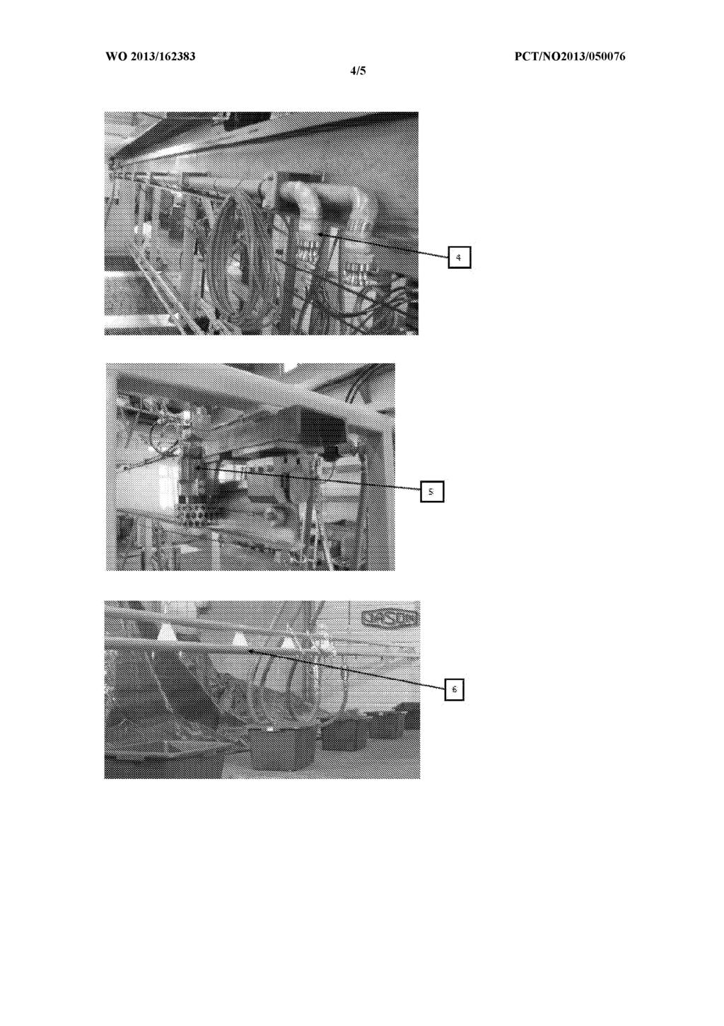
10 Photograph 2: The beam section is suspended from two slide bearings of synthetic material. The beam section can be pushed/pulled back and forth. Photograph 3: The two bearing points are secured t o a standard U-section which forms the actual anchorage t o the vessel's steel structure onto which it is preferably welded. Photograph 4 : On one side of the support beam web are two pipes with a rapid release coupling at either end. These pipes are for supply of dispersing fluid via hoses t o the twin manifold. Photograph 5: On the other side of the support beam is a mechanism which pushes/pulls the support beam back and forth. This mechanism may be a toothed rack or a wire, where the actual drive is a hydraulic or electric motor, or a mechanism having one or more hydraulic cylinders. Photograph 5 shows an apparatus with wire rope drive. Photograph 6: As mentioned above, a twin manifold is included where a row of spray nozzles has different capacity (100% and 25% nominal capacity). By alternating between the two rows of nozzles, it is possible t o meter/apply dispersing fluid on the basis of the thickness and condition of the oil film. In addition t o alternating between the two rows of nozzles, separately or together, the pressure in the manifolds can be varied steplessly, which in turn results in a stepless variable metering of dispersing fluid. Photograph 7: The manifold is hoisted up and down in that it is suspended from two lines. Each line runs via a pulley attached t o the section and t o a small hydraulically operated winch that is remote-controlled from the radio control. Photograph 8: Dispersing fluid is passed t o the nozzle manifold by means of hoses that are connected using rapid release couplings. At the inlet t o the manifolds is a pressure-controlled shut-off valve. The task of this valve is t o instantly shut off supply of fluid t o the manifold such that hoses and pipes do not run dry in the event of a break in the dispersion operation. This results in a precise starting and stopping of spray from the nozzles when the shut-off valve t o the individual manifold is operated.
11 Photograph 9: The shut-off valve t o each manifold is equipped with a hydraulic actuator and with both visual and electrical indicator for open/closed position. Control of the valve is from the radio control.
12 P a t e n t c l a i m s 1. An apparatus for applying a dispersant to an oil slick at sea from a boat, the apparatus comprising two support beams with associated nozzle manifolds, c h a r a c t e r i s e d i n that the support beams are mounted inside a ship's hull and are adapted to be passed out through a hatch or opening on each side of the hull, the apparatus having an inactive, retracted position when it is not in use, and an active, extended position when it is in use, and wherein the hatches or openings and the support beams with associated nozzle manifolds are arranged such that the dispersant, when the apparatus is in use, hits the sea/oil slick ahead of the breaking point of the boat's bow wave. 2. An apparatus according to claim 1, wherein the support beams are adapted to be pushed out and in through the ship's hull essentially horizontally and essentially transverse to the longitudinal direction of the boat, the support beams being pushed by a mechanical or hydraulic mechanism, which mechanism comprising drive via toothed rack, wire rope drive, cylinder and/or telescope. An apparatus according to claim 1 or 2, wherein each of the support beams is provided with a nozzle manifold and nozzles, the nozzle manifold being adapted to be capable of being lowered and raised relative to the sea surface and the support beam from which it is suspended. An apparatus according to claim 3, wherein the nozzle manifold is a twin manifold and comprises two rows of nozzles, the rows having different capacity, wherein the metering of the dispersant onto an oil slick at sea can be adjusted by alternating between or combining the capacity of the two rows. An apparatus according to claim 3, wherein the nozzle manifold comprises heating cables for de-icing.
13 6. An apparatus according to claim 3, wherein raising and lowering of the nozzle manifold is to be controlled from a wireless portable control panel (radio control).
14
15
16
17
18
19 n erna ona app ca on o. PCT/NO201 3/ A. CLASSIFICATION OF SUBJECT MATTER IPC: see extra sheet According to International Patent Classification (IPC) or to both national classification and IPC B. FIELDS SEARCHED Minimum documentation searched (classification system followed by classification symbols) IPC: B63B, E02B Documentation searched other than minimum documentation to the extent that such documents are included in the fields searched SE, DK, Fl, NO classes as above Electronic data base consulted during the international search (name of data base and, where practicable, search terms used) EPO-lnternal, PAJ, WPI data C. DOCUMENTS CONSIDERED TO BE RELEVANT Category* Citation of document, with indication, where appropriate, of the relevant passages Relevant to claim No. A NO B (NOREN AS -(B1 ) NOREN BERGEN AS [NO]), March 2000 ( ); abstract; figures P, A W O A 1 (FUGRO GEOTEAM AS ET AL), 3 May ( ); abstract; figures A EP A2 (CLEANSEAS OIL POLLUTION CONTRO), January 1982 ( ); abstract; figures A W O A 1 (DELAVAN LTD ET AL), 1 October ( ) ; abstract; figures Further documents are listed in the continuation of Box C. See patent family annex. * Special categories of cited documents: " later document published after the international fding date or priority "A" document defining the general state of the art which is not considered date and not in conflict with the application but cited to understand to be of particular relevance the principle or theory underlying the invention "E" earlier application or patent but published on or after the international 'X" document of particular relevance; the claimed invention cannot be filing date considered novel or cannot be considered to involve an inventive "L" document which may throw doubts on priority claim(s) or which is step when the document is taken alone cited to establish the publication date of another citation or other Ύ " document of particular relevance; the claimed invention cannot be special reason (as specified) considered to involve an inventive step when the document is "O" document referring to an oral disclosure, use, exhibition or other combined with one or more other such documents, such combination means being obvious to a person skilled in the art "P" document published prior to the international filing date but later than ' '&" document member of the same patent family the priority date claimed Date of the actual completion of the international search Date of mailing of the international search report Name and mailing address of the ISA/SE Patent- och registreringsverket Box 5055 Authorized officer Bjorn Lindkvist S STOCKHOLM Facsimile No Telephone No Form PCT/ISA/210 (second sheet) (July 2009)
20 n erna ona app ca on o. PCT/NO201 3/ C (Continuation). DOCUMENTS CONSIDERED TO BE RELEVANT Category* Citation of document, with indication, where appropriate, of the relevant passages Relevant to claim No. A EP A 1 (ARCTIA SAARISTOVARUSTAMO OY), 10 1, 2 August ( ); abstract; figures A WO A 1 (ORC A B ET AL), 4 November ( ); abstract; figures Form PCT/ISA/210 (continuation of second sheet) (July 2009)
21 n erna ona app ca on o. PCT/NO201 3/ Continuation of: second sheet International Patent Classification (IPC) E02B 75/04 ( ) B63B 35/32 ( ) Form PCT/ISA/210 (extra sheet) (July 2009)
22 n erna ona app ca on o. Information on patent family members PCT/NO201 3/ NO B 15/03/2000 NONE O A 1 03/05/201 2 NO A 30/04/201 2 EP A2 06/01/1 982 J P A 10/05/1 982 NO A 29/1 2/1 981 O A 1 01/1 0/1 981 DE D 1 26/04/1 984 DK A 18/1 1/1 981 EP B 1 21/03/1 984 J P S A 08/04/1 982 J P B 25/07/1 988 NO A 17/1 1/1 981 EP A 1 10/08/201 1 F l A O 28/01/201 1 F l A O 30/1 1/201 0 F l A O 28/01/201 0 W O A 1 04/1 1/201 0 A U A 1 17/1 1/201 1 CA A 1 04/1 1/201 0 CN A 25/04/201 2 EP A 1 07/03/201 2 KR A 13/03/201 2 RU A 10/06/201 3 US A 1 16/02/201 2 Form PCT/ISA/210 (patent family annex) (July 2009)
Are We There Yet? IPv6 as Related to GDP per Capita. By Alain Durand November 28 th,` 2016
 Are We There Yet? as Related to By Alain Durand November 28 th,` 2016 Quesons for this Study: I. Where are we across the globe with adoption? a. Is deployed uniformly? b. Is there a rich country/poor country
FIG. 1. Specific Speed (N ) 5 August 2010 ( ) WO 2010/ Al. (43) International Publication Date
 5 August 2010 ( ) WO 2010/ Al. (43) International Publication Date") (12) INTERNATIONAL APPLICATION PUBLISHED UNDER THE PATENT COOPERATION TREATY (PCT) (19) World Intellectual Property Organization International Bureau (43) International Publication Date (10) International
(12) INTERNATIONAL APPLICATION PUBLISHED UNDER THE PATENT COOPERATION TREATY (PCT) (19) World Intellectual Property Organization International Bureau (43) International Publication Date (10) International
EP A1 (19) (11) EP A1. (12) EUROPEAN PATENT APPLICATION published in accordance with Art. 153(4) EPC
 (11) EP A1. (12) EUROPEAN PATENT APPLICATION published in accordance with Art. 153(4) EPC") (19) (12) EUROPEAN PATENT APPLICATION published in accordance with Art. 153(4) EPC (11) EP 2 481 666 A1 (43) Date of publication: 01.08.2012 Bulletin 2012/31 (21) Application number: 10826779.0 (22) Date
(19) (12) EUROPEAN PATENT APPLICATION published in accordance with Art. 153(4) EPC (11) EP 2 481 666 A1 (43) Date of publication: 01.08.2012 Bulletin 2012/31 (21) Application number: 10826779.0 (22) Date
(12) STANDARD PATENT (11) Application No. AU B2 (19) AUSTRALIAN PATENT OFFICE
 STANDARD PATENT (11) Application No. AU B2 (19) AUSTRALIAN PATENT OFFICE") (12) STANDARD PATENT (11) Application No. AU 2011283645 B2 (19) AUSTRALIAN PATENT OFFICE (54) Title Apparatus and method for heat curing of pipe liners (51) International Patent Classification(s) F16L
(12) STANDARD PATENT (11) Application No. AU 2011283645 B2 (19) AUSTRALIAN PATENT OFFICE (54) Title Apparatus and method for heat curing of pipe liners (51) International Patent Classification(s) F16L
TEPZZ 9_ 9 A_T EP A1 (19) (11) EP A1 (12) EUROPEAN PATENT APPLICATION. (43) Date of publication: Bulletin 2015/36
 (11) EP A1 (12) EUROPEAN PATENT APPLICATION. (43) Date of publication: Bulletin 2015/36") (19) TEPZZ 9_ 9 A_T (11) EP 2 913 293 A1 (12) EUROPEAN PATENT APPLICATION (43) Date of publication: 02.09.2015 Bulletin 2015/36 (51) Int Cl.: B66D 1/38 (2006.01) (21) Application number: 15250003.9 (22)
(19) TEPZZ 9_ 9 A_T (11) EP 2 913 293 A1 (12) EUROPEAN PATENT APPLICATION (43) Date of publication: 02.09.2015 Bulletin 2015/36 (51) Int Cl.: B66D 1/38 (2006.01) (21) Application number: 15250003.9 (22)
TEPZZ A_T EP A1 (19) (11) EP A1 (12) EUROPEAN PATENT APPLICATION. (43) Date of publication: Bulletin 2013/48
 (11) EP A1 (12) EUROPEAN PATENT APPLICATION. (43) Date of publication: Bulletin 2013/48") (19) TEPZZ 66654 A_T (11) EP 2 666 543 A1 (12) EUROPEAN PATENT APPLICATION (43) Date of publication: 27.11.2013 Bulletin 2013/48 (51) Int Cl.: B02C 13/286 (2006.01) B02C 13/18 (2006.01) (21) Application
(19) TEPZZ 66654 A_T (11) EP 2 666 543 A1 (12) EUROPEAN PATENT APPLICATION (43) Date of publication: 27.11.2013 Bulletin 2013/48 (51) Int Cl.: B02C 13/286 (2006.01) B02C 13/18 (2006.01) (21) Application
TEPZZ _ Z684A_T EP A1 (19) (11) EP A1 (12) EUROPEAN PATENT APPLICATION. (51) Int Cl.: A01D 34/82 ( )
 (11) EP A1 (12) EUROPEAN PATENT APPLICATION. (51) Int Cl.: A01D 34/82 ( )") (19) TEPZZ _ Z684A_T (11) EP 3 1 684 A1 (12) EUROPEAN PATENT APPLICATION (43) Date of publication: 2.01.17 Bulletin 17/04 (1) Int Cl.: A01D 34/82 (06.01) (21) Application number: 1617949.9 (22) Date of
(19) TEPZZ _ Z684A_T (11) EP 3 1 684 A1 (12) EUROPEAN PATENT APPLICATION (43) Date of publication: 2.01.17 Bulletin 17/04 (1) Int Cl.: A01D 34/82 (06.01) (21) Application number: 1617949.9 (22) Date of
(12) STANDARD PATENT (11) Application No. AU B2 (19) AUSTRALIAN PATENT OFFICE
 STANDARD PATENT (11) Application No. AU B2 (19) AUSTRALIAN PATENT OFFICE") (12) STANDARD PATENT (11) Application No. AU 2013222067 B2 (19) AUSTRALIAN PATENT OFFICE (54) Title Apparatus and method for repairing pipes (51) International Patent Classification(s) F16L 55/162 (2006.01)
(12) STANDARD PATENT (11) Application No. AU 2013222067 B2 (19) AUSTRALIAN PATENT OFFICE (54) Title Apparatus and method for repairing pipes (51) International Patent Classification(s) F16L 55/162 (2006.01)
TEPZZ A_T EP A1 (19) (11) EP A1 (12) EUROPEAN PATENT APPLICATION
 (11) EP A1 (12) EUROPEAN PATENT APPLICATION") (19) TEPZZ 55475 A_T (11) EP 2 554 752 A1 (12) EUROPEAN PATENT APPLICATION (43) Date of publication: 06.02.2013 Bulletin 2013/06 (21) Application number: 11176100.3 (51) Int Cl.: E02D 7/06 (2006.01) E02D
(19) TEPZZ 55475 A_T (11) EP 2 554 752 A1 (12) EUROPEAN PATENT APPLICATION (43) Date of publication: 06.02.2013 Bulletin 2013/06 (21) Application number: 11176100.3 (51) Int Cl.: E02D 7/06 (2006.01) E02D
TEPZZ 6Z4795A T EP A2 (19) (11) EP A2 (12) EUROPEAN PATENT APPLICATION. (43) Date of publication: Bulletin 2013/25
 (11) EP A2 (12) EUROPEAN PATENT APPLICATION. (43) Date of publication: Bulletin 2013/25") (19) TEPZZ 6Z479A T (11) EP 2 604 79 A2 (12) EUROPEAN PATENT APPLICATION (43) Date of publication: 19.06.2013 Bulletin 2013/2 (1) Int Cl.: F01D /18 (2006.01) (21) Application number: 12194748. (22) Date
(19) TEPZZ 6Z479A T (11) EP 2 604 79 A2 (12) EUROPEAN PATENT APPLICATION (43) Date of publication: 19.06.2013 Bulletin 2013/2 (1) Int Cl.: F01D /18 (2006.01) (21) Application number: 12194748. (22) Date
TEPZZ 54Z549A_T EP A1 (19) (11) EP A1. (12) EUROPEAN PATENT APPLICATION published in accordance with Art.
 (11) EP A1. (12) EUROPEAN PATENT APPLICATION published in accordance with Art.") (19) TEPZZ 54Z549A_T (11) EP 2 540 549 A1 (12) EUROPEAN PATENT APPLICATION published in accordance with Art. 153(4) EPC (43) Date of publication: 02.01.2013 Bulletin 2013/01 (21) Application number: 11747089.8
(19) TEPZZ 54Z549A_T (11) EP 2 540 549 A1 (12) EUROPEAN PATENT APPLICATION published in accordance with Art. 153(4) EPC (43) Date of publication: 02.01.2013 Bulletin 2013/01 (21) Application number: 11747089.8
WO 2007/ Al PCT. (19) World Intellectual Property Organization International Bureau
 World Intellectual Property Organization International Bureau") (12) INTERNATIONAL APPLICATION PUBLISHED UNDER THE PATENT COOPERATION TREATY (PCT) (19) World Intellectual Property Organization International Bureau (43) International Publication Date (10) International
(12) INTERNATIONAL APPLICATION PUBLISHED UNDER THE PATENT COOPERATION TREATY (PCT) (19) World Intellectual Property Organization International Bureau (43) International Publication Date (10) International
TEPZZ 69Z 85A T EP A2 (19) (11) EP A2 (12) EUROPEAN PATENT APPLICATION
 (11) EP A2 (12) EUROPEAN PATENT APPLICATION") (19) TEPZZ 69Z 8A T (11) EP 2 690 28 A2 (12) EUROPEAN PATENT APPLICATION (43) Date of publication: 29.01.14 Bulletin 14/0 (21) Application number: 13177476.2 (1) Int Cl.: F03D 7/02 (06.01) F03D 7/00 (06.01)
(19) TEPZZ 69Z 8A T (11) EP 2 690 28 A2 (12) EUROPEAN PATENT APPLICATION (43) Date of publication: 29.01.14 Bulletin 14/0 (21) Application number: 13177476.2 (1) Int Cl.: F03D 7/02 (06.01) F03D 7/00 (06.01)
CERN Personnel Statistics
 CERN/TREF/439 4 May 2017 Organisation européenne pour la recherche nucléaire European Organization for Nuclear Research Laboratoire Européen pour la Physique des Particules European Laboratory for Particle
(12) INTERNATIONAL APPLICATION PUBLISHED UNDER THE PATENT COOPERATION TREATY (PCT)
 INTERNATIONAL APPLICATION PUBLISHED UNDER THE PATENT COOPERATION TREATY (PCT)") (12) INTERNATIONAL APPLICATION PUBLISHED UNDER THE PATENT COOPERATION TREATY (PCT) (19) World Intellectual Property Organization International Bureau (10) International Publication Number (43) International
(12) INTERNATIONAL APPLICATION PUBLISHED UNDER THE PATENT COOPERATION TREATY (PCT) (19) World Intellectual Property Organization International Bureau (10) International Publication Number (43) International
Update of trade weights data underlying the EERs and HCIs
 August 2017 Update of trade weights data underlying the EERs and HCIs The trade weights underlying the calculation of the effective exchange rates (EERs) of the euro and the harmonised competitiveness
TEPZZ _ 5778A_T EP A1 (19) (11) EP A1 (12) EUROPEAN PATENT APPLICATION
 (11) EP A1 (12) EUROPEAN PATENT APPLICATION") (19) TEPZZ _ 778A_T (11) EP 3 13 778 A1 (12) EUROPEAN PATENT APPLICATION (43) Date of publication: 01.03.2017 Bulletin 2017/09 (21) Application number: 1183169.0 (1) Int Cl.: C21D 9/6 (2006.01) F27B 9/04
(19) TEPZZ _ 778A_T (11) EP 3 13 778 A1 (12) EUROPEAN PATENT APPLICATION (43) Date of publication: 01.03.2017 Bulletin 2017/09 (21) Application number: 1183169.0 (1) Int Cl.: C21D 9/6 (2006.01) F27B 9/04
*EP A2* EP A2 (19) (11) EP A2 (12) EUROPEAN PATENT APPLICATION. (43) Date of publication: Bulletin 2003/34
 (11) EP A2 (12) EUROPEAN PATENT APPLICATION. (43) Date of publication: Bulletin 2003/34") (19) Europäisches Patentamt European Patent Office Office européen des brevets *EP00133679A2* (11) EP 1 336 79 A2 (12) EUROPEAN PATENT APPLICATION (43) Date of publication: 20.08.2003 Bulletin 2003/34
(19) Europäisches Patentamt European Patent Office Office européen des brevets *EP00133679A2* (11) EP 1 336 79 A2 (12) EUROPEAN PATENT APPLICATION (43) Date of publication: 20.08.2003 Bulletin 2003/34
I International Bureau (10) International Publication Number (43) International Publication Date
 International Publication Number (43) International Publication Date") (12) INTERNATIONAL APPLICATION PUBLISHED UNDER THE PATENT COOPERATION TREATY (PCT) (19) World Intellectual Property Organization I International Bureau (10) International Publication Number (43) International
(12) INTERNATIONAL APPLICATION PUBLISHED UNDER THE PATENT COOPERATION TREATY (PCT) (19) World Intellectual Property Organization I International Bureau (10) International Publication Number (43) International
(51) Int Cl.: B64C 39/02 ( ) A63H 29/16 ( )
 Int Cl.: B64C 39/02 ( ) A63H 29/16 ( )") (19) TEPZZ Z64 7A_T (11) EP 3 06 427 A1 (12) EUROPEAN PATENT APPLICATION (43) Date of publication: 17.08.16 Bulletin 16/33 (1) Int Cl.: B64C 39/02 (06.01) A63H 29/16 (06.01) (21) Application number: 1389.2
(19) TEPZZ Z64 7A_T (11) EP 3 06 427 A1 (12) EUROPEAN PATENT APPLICATION (43) Date of publication: 17.08.16 Bulletin 16/33 (1) Int Cl.: B64C 39/02 (06.01) A63H 29/16 (06.01) (21) Application number: 1389.2
Boom for a load handling machine.
 Loughborough University Institutional Repository Boom for a load handling machine This item was submitted to Loughborough University's Institutional Repository by the/an author. Citation: NURSE, A.D....et
1. Annex 1: Indicators
 1. Annex 1: Indicators 1.1 Input indicators 1. Financial envelope of AGN operating agreements over 7 years, in * Euro 613 740 613 740 572 773 553 605 553 605 638 904 638 904 *Reported budget outcome 2.
The UPOV Convention: an International Standard
 EU Plant Variety Rights in the 21 st Century Conference on the outcome of the evaluation of the Community Plant Variety Rights Regime The UPOV Convention: an International Standard Peter Button (Vice Secretary-General,
Total Frequency Percent CAPS Graduate Graduate Intensive English
 Total Enrollment Fall, Fall I 2006: 8150 All Students by School All Students By Status CAPS & Traditional UG 4722 57.9 Continuing 5926 72.7 Graduate 3406 41.8 First-time Freshman 911 11.2 Intensive English
Installation and operation manual SUNWOOD MARINO LPG
 Installation and operation manual SUNWOOD MARINO Version: Natural Gas LPG Specifications Manufacturer Sunderman Openhaarden V.O.F. / Sunwood Contact details Christiaan Huygensstraat 10 2665 KX Bleiswijk
Summary Charts Scenario 3 - Low Change Scenario
 7/26/2016 U:\POUPU000.2015g_TD model 9\20160723TDM9\TDM_9p_Model_3_Sum_.Scen03_E70_20160726.xlsx Page 1 Summary Charts Scenario 3 - Low Change Scenario Equivalent domestic postage 70% priority domestic
MARIE SKŁODOWSKA-CURIE ACTIONS STATISTICS INDIVIDUAL FELLOWSHIPS
 MARIE SKŁODOWSKA-CURIE ACTIONS STATISTICS INDIVIDUAL FELLOWSHIPS Dernière mise à jour : Février 2019 1 EF ST EF CAR/RI SE GF European Fellowships Standard European Fellowships CAR/RI Society and Enterprise
The Unitor Gas Distribution System
 The Unitor Gas Distribution System By Leif Andersen, Technical Product Manager Welding, WSS High-pressure gas cylinders inside the ship s hull is a safety risk to crew and vessel and should always be avoided.
WO 2007/ Al PCT. (19) World Intellectual Property Organization International Bureau
 World Intellectual Property Organization International Bureau") (12) INTERNATIONAL APPLICATION PUBLISHED UNDER THE PATENT COOPERATION TREATY (PCT) (19) World Intellectual Property Organization International Bureau (43) International Publication Date (10) International
(12) INTERNATIONAL APPLICATION PUBLISHED UNDER THE PATENT COOPERATION TREATY (PCT) (19) World Intellectual Property Organization International Bureau (43) International Publication Date (10) International
Summary Charts Scenario 1 - Base Scenario
 7/26/2016 U:\POUPU000.2015g_TD model 9\20160723TDM9\TDM_9p_Model_3_Sum_.Scen01_E70_20160726.xlsx Page 1 Summary Charts Scenario 1 - Base Scenario Equivalent domestic postage 70% priority domestic postage
(12) United States Patent
 United States Patent") (12) United States Patent US007137200B2 (10) Patent No.: US 7,137,200 B2 Shepherd et al. (45) Date of Patent: Nov. 21, 2006 (54) METHOD OF CONSTRUCTING A BUOY 3,665,882 A * 5/1972 Georgiev et al.... 114,226
(12) United States Patent US007137200B2 (10) Patent No.: US 7,137,200 B2 Shepherd et al. (45) Date of Patent: Nov. 21, 2006 (54) METHOD OF CONSTRUCTING A BUOY 3,665,882 A * 5/1972 Georgiev et al.... 114,226
TEPZZ 7_687ZA_T EP A1 (19) (11) EP A1 (12) EUROPEAN PATENT APPLICATION. (43) Date of publication: Bulletin 2014/15
 (11) EP A1 (12) EUROPEAN PATENT APPLICATION. (43) Date of publication: Bulletin 2014/15") (19) TEPZZ 7_687ZA_T (11) EP 2 716 870 A1 (12) EUROPEAN PATENT APPLICATION (43) Date of publication: 09.04.2014 Bulletin 2014/15 (51) Int Cl.: F01D 5/20 (2006.01) (21) Application number: 13187418.2 (22)
(19) TEPZZ 7_687ZA_T (11) EP 2 716 870 A1 (12) EUROPEAN PATENT APPLICATION (43) Date of publication: 09.04.2014 Bulletin 2014/15 (51) Int Cl.: F01D 5/20 (2006.01) (21) Application number: 13187418.2 (22)
WO 2016/ Al. 24 March 2016 ( ) P O P C T
 P O P C T") (12) INTERNATIONAL APPLICATION PUBLISHED UNDER THE PATENT COOPERATION TREATY (PCT) (19) World Intellectual Property Organization International Bureau (10) International Publication Number (43) International
(12) INTERNATIONAL APPLICATION PUBLISHED UNDER THE PATENT COOPERATION TREATY (PCT) (19) World Intellectual Property Organization International Bureau (10) International Publication Number (43) International
ULMATEC LAUNCH AND RECOVERY SYSTEMS
 M L U NC LAU MS ERY V ECO DR N HA C E AT TE SYS S R LA ULMATEC LAUNCH AND RECOVERY SYSTEMS Ulmatec develops efficient, safe and robust solutions for handling remotely operated vehicles (ROVs) from ships
Fresh Woter Aquifer : C u t r - - _Casting. Casing,^ Perforation Clusters FIG. 1
 (12) INTERNATIONAL APPLICATION PUBLISHED UNDER THE PATENT COOPERATION TREATY (PCT) (19) World Intellectual Property Organization International Bureau (10) International Publication Number (43) International
TEPZZ 7 Z67A_T EP A1 (19) (11) EP A1 (12) EUROPEAN PATENT APPLICATION
 (11) EP A1 (12) EUROPEAN PATENT APPLICATION") (19) TEPZZ 7 Z67A_T (11) EP 2 711 067 A1 (12) EUROPEAN PATENT APPLICATION (43) Date of publication: 26.03.14 Bulletin 14/13 (21) Application number: 12188.1 (1) Int Cl.: B01D 3/60 (06.01) B01D 3/92 (06.01)
(19) TEPZZ 7 Z67A_T (11) EP 2 711 067 A1 (12) EUROPEAN PATENT APPLICATION (43) Date of publication: 26.03.14 Bulletin 14/13 (21) Application number: 12188.1 (1) Int Cl.: B01D 3/60 (06.01) B01D 3/92 (06.01)
(12) United States Patent (10) Patent No.: US 6,601,826 B1
 United States Patent (10) Patent No.: US 6,601,826 B1") USOO66O1826B1 (12) United States Patent (10) Patent No.: Granata (45) Date of Patent: Aug. 5, 2003 (54) LOW-LEVEL LIFT 4,858,888 A 8/1989 Cruz et al.... 254/122 5,192,053 A * 3/1993 Sehlstedt... 254/122
USOO66O1826B1 (12) United States Patent (10) Patent No.: Granata (45) Date of Patent: Aug. 5, 2003 (54) LOW-LEVEL LIFT 4,858,888 A 8/1989 Cruz et al.... 254/122 5,192,053 A * 3/1993 Sehlstedt... 254/122
Lightweight portable training device to simulate kayaking
 University of Central Florida UCF Patents Patent Lightweight portable training device to simulate kayaking 12-7-2010 Ronald Eaglin University of Central Florida Find similar works at: http://stars.library.ucf.edu/patents
WO 2014/ Al. 17 April 2014 ( ) P O P C T
 P O P C T") (12) INTERNATIONAL APPLICATION PUBLISHED UNDER THE PATENT COOPERATION TREATY (PCT) (19) World Intellectual Property Organization International Bureau (10) International Publication Number (43) International
(12) INTERNATIONAL APPLICATION PUBLISHED UNDER THE PATENT COOPERATION TREATY (PCT) (19) World Intellectual Property Organization International Bureau (10) International Publication Number (43) International
PCT WO 2007/ A2
 (12) INTERNATIONAL APPLICATION PUBLISHED UNDER THE PATENT COOPERATION TREATY (PCT) (19) World Intellectual Property Organization International Bureau (43) International Publication Date (10) International
USOO A United States Patent (19) 11 Patent Number: 5,893,786 Stevens 45 Date of Patent: Apr. 13, 1999
 11 Patent Number: 5,893,786 Stevens 45 Date of Patent: Apr. 13, 1999") III IIII USOO589.3786A United States Patent (19) 11 Patent Number: Stevens 45 Date of Patent: Apr. 13, 1999 54 AUTOMATIC TELESCOPING BOUYANT 5,582,127 12/1996 Willis et al.... 116/210 IDENTIFICATION DEVICE
III IIII USOO589.3786A United States Patent (19) 11 Patent Number: Stevens 45 Date of Patent: Apr. 13, 1999 54 AUTOMATIC TELESCOPING BOUYANT 5,582,127 12/1996 Willis et al.... 116/210 IDENTIFICATION DEVICE
Device for atomizing a liquid
 Page 1 of 6 Device for atomizing a liquid Abstract ( 5 of 5 ) United States Patent 4,504,014 Leuning March 12, 1985 A device (10) for atomizing a liquid is disclosed. The device (10) includes a sprayhead
ROAD SAFETY: Towards a European Road Safety Area: Policy orientations on road safety
 ROAD SAFETY: Towards a European Road Safety Area: Policy orientations on road safety TWO MAIN POLICY PAPERS WHITE PAPER 2011: Towards a zero-vision on road safety POLICY ORIENTATIONS ON ROAD SAFETY 2011-2020
(12) United States Patent (10) Patent No.: US 6,456,197 B1
 United States Patent (10) Patent No.: US 6,456,197 B1") USOO6456197B1 (12) United States Patent (10) Patent No.: Lauritsen et al. (45) Date of Patent: Sep. 24, 2002 (54) OIL-IN-WATER DETECTOR BUOY (56) References Cited ARRANGEMENT U.S. PATENT DOCUMENTS (75)
USOO6456197B1 (12) United States Patent (10) Patent No.: Lauritsen et al. (45) Date of Patent: Sep. 24, 2002 (54) OIL-IN-WATER DETECTOR BUOY (56) References Cited ARRANGEMENT U.S. PATENT DOCUMENTS (75)
United States Patent (19) Condo et al.
 Condo et al.") United States Patent (19) Condo et al. 54 BOXING TRAINING APPARATUS 75 Inventors: Girolamao Condo; Luigi Trocola, both of Eislingen, Fed. Rep. of Germany 73) Assignee: Petra Condo, Eislingen, Fed. Rep.
United States Patent (19) Condo et al. 54 BOXING TRAINING APPARATUS 75 Inventors: Girolamao Condo; Luigi Trocola, both of Eislingen, Fed. Rep. of Germany 73) Assignee: Petra Condo, Eislingen, Fed. Rep.
(43) International Publication Date WO 2014/ Al 3 April 2014 ( ) W P O P C T
 International Publication Date WO 2014/ Al 3 April 2014 ( ) W P O P C T") (12) INTERNATIONAL APPLICATION PUBLISHED UNDER THE PATENT COOPERATION TREATY (PCT) (19) World Intellectual Property Organization International Bureau (10) International Publication Number (43) International
(12) INTERNATIONAL APPLICATION PUBLISHED UNDER THE PATENT COOPERATION TREATY (PCT) (19) World Intellectual Property Organization International Bureau (10) International Publication Number (43) International
TEPZZ 5_84 8A_T EP A1 (19) (11) EP A1. (12) EUROPEAN PATENT APPLICATION published in accordance with Art.
 (11) EP A1. (12) EUROPEAN PATENT APPLICATION published in accordance with Art.") (19) TEPZZ 5_84 8A_T (11) EP 2 518 438 A1 (12) EUROPEAN PATENT APPLICATION published in accordance with Art. 153(4) EPC (43) Date of publication: 31.10.2012 Bulletin 2012/44 (21) Application number: 10839590.6
(19) TEPZZ 5_84 8A_T (11) EP 2 518 438 A1 (12) EUROPEAN PATENT APPLICATION published in accordance with Art. 153(4) EPC (43) Date of publication: 31.10.2012 Bulletin 2012/44 (21) Application number: 10839590.6
IBAN Mandatory Countries for International Payments
 IBAN Mandatory Countries for International Payments SWIFT Standards (IBAN Mandatory) ISO CTRY CODE SEPA Format of Receiver Bank Account Number Albania AL No IBAN-28 Andorra AD No IBAN-24 Austria AT Yes
(12) Patent Application Publication (10) Pub. No.: US 2008/ A1
 Patent Application Publication (10) Pub. No.: US 2008/ A1") (19) United States (12) Patent Application Publication (10) Pub. No.: US 2008/0066794 A1 Durfee US 2008 OO66794A1 (43) Pub. Date: Mar. 20, 2008 (54) (76) (21) (22) (60) AUTOMATIC HUNTING BLIND Inventor:
(19) United States (12) Patent Application Publication (10) Pub. No.: US 2008/0066794 A1 Durfee US 2008 OO66794A1 (43) Pub. Date: Mar. 20, 2008 (54) (76) (21) (22) (60) AUTOMATIC HUNTING BLIND Inventor:
HANDBOOK. Squeeze Off Unit SOU 400. Please refer any queries to:
 HANDBOOK Squeeze Off Unit SOU 400 Please refer any queries to: Hy Ram Engineering Co Ltd Pelham Street Mansfield Nottinghamshire NG18 2EY Telephone No: (01623) 422982 Please note all queries should state
PIN Flash 18 - Background tables
 PIN Flash 18 - Background tables Definition of deaths on urban/rural rural roads How the urban/rural distinction is made in the statistics that your country provides to CARE CARE Deaths on rural roads
HANDBOOK. Squeeze Off Unit SOU 250. Please refer any queries to:
 HANDBOOK Squeeze Off Unit SOU 250 Please refer any queries to: Hy Ram Engineering Co Ltd Pelham Street Mansfield Nottinghamshire NG18 2EY Telephone No: (01623) 422982 Please note all queries should state
Floor Mount Socket. T: +44 (0) F: +44 (0)
 F: +44 (0)") G-Davit : Floor Mount Socket USER INSTRUCTION MANUAL A davit socket for installation bolted to a high strength flooring material. Suitable for both fall arrest use and lifting. EN795 Class B, PPE Anchor
G-Davit : Floor Mount Socket USER INSTRUCTION MANUAL A davit socket for installation bolted to a high strength flooring material. Suitable for both fall arrest use and lifting. EN795 Class B, PPE Anchor
The salient features of the 27m Ocean Shuttle Catamaran Hull Designs
 The salient features of the 27m Ocean Shuttle Catamaran Hull Designs The hull form is a semi-planing type catamaran. It employs a combination of symmetrical and asymmetrical sponson shapes, thereby combining
7%averzazz az72eways. AZafaa 77/owa soy. /v/a/y7 Oa. July 7, 1964 W. A. THOMPSON 3,139,732 BOAT STABILIZING AND LIFTING DEVICE.
 July 7, 1964 W. A. THOMPSON Filed May 5, 1961 BOAT STABILIZING AND LIFTING DEVICE 2 Sheets-Sheet /v/a/y7 Oa AZafaa 77/owa soy 7%averzazz az72eways July 7, 1964 Filed May 5, l96l W. A. THOMPSON BOAT STABILIZING
STRUCTURAL MEMBERS OF A SHIP. compartment stem frame beam bracket girder stern post hull angle bar stiffener
 Unit 2 SHIPS AND SHIPS TERMS STRUCTURAL MEMBERS OF A SHIP Basic terms shell plating strake keel deck tank top floor stringer buoyancy strength stability bulkhead compartment stem frame beam bracket girder
Exposure estimations before and after the new EFSA-Guidance ECPA s perspective based on examples
 Exposure estimations before and after the new EFSA-Guidance ECPA s perspective based on examples Overview Lack of clear guidance & room for interpretation Following the guidance document finalisation by
(12) Patent Application Publication (10) Pub. No.: US 2009/ A1
 Patent Application Publication (10) Pub. No.: US 2009/ A1") (19) United States US 20090215566A1 (12) Patent Application Publication (10) Pub. No.: US 2009/0215566A1 Braedt (43) Pub. Date: Aug. 27, 2009 (54) MULTIPLE SPROCKETASSEMBLY Publication Classification (75)
(19) United States US 20090215566A1 (12) Patent Application Publication (10) Pub. No.: US 2009/0215566A1 Braedt (43) Pub. Date: Aug. 27, 2009 (54) MULTIPLE SPROCKETASSEMBLY Publication Classification (75)
VEFT Aerospace Technology
 Douglas S. Walkinshaw Patent Pending PCT/CA2007/001125 Page 1 (WO/2007/147259) ENTRAINMENT AIR FLOW CONTROL AND FILTRATION DEVICES Latest bibliographic data on file with the International Bureau Publication
Gebrauchsanleitung. Instructions for Use. Instructions d utilisation. Instrucciones de uso Istruzioni per l uso
 Gebrauchsanleitung DE HU Instructions for Use GB SL Instructions d utilisation FR CZ Instrucciones de uso Istruzioni per l uso ES IT TR RU Gebruiksaanwijzing Instruções de serviço NL PT BG GR Brugsanvisning
United States Patent (19)
") United States Patent (19) Fujikawa 54 HYDRAULIC CONTROL SYSTEM FOR A ROCK DRILL (75) Inventor: Kozo Fujikawa, Hiroshima, Japan 73) Assignee: Toyo Kogyo Co., Ltd., Hiroshima, Japan 21 Appl. No.: 194,391
United States Patent (19) Fujikawa 54 HYDRAULIC CONTROL SYSTEM FOR A ROCK DRILL (75) Inventor: Kozo Fujikawa, Hiroshima, Japan 73) Assignee: Toyo Kogyo Co., Ltd., Hiroshima, Japan 21 Appl. No.: 194,391
(12) Patent Application Publication (10) Pub. No.: US 2006/ A1
 Patent Application Publication (10) Pub. No.: US 2006/ A1") (19) United States US 20060289584A1 (12) Patent Application Publication (10) Pub. No.: US 2006/0289584A1 Lu (43) Pub. Date: Dec. 28, 2006 (54) PROTECTIVE BAG HAVING INNER PAD FOR SURFBOARD (76) Inventor:
(19) United States US 20060289584A1 (12) Patent Application Publication (10) Pub. No.: US 2006/0289584A1 Lu (43) Pub. Date: Dec. 28, 2006 (54) PROTECTIVE BAG HAVING INNER PAD FOR SURFBOARD (76) Inventor:
Friday, December 28, 2001 United States Patent: 4,100,941 Page: 1. United States Patent 4,100,941 Ainsworth, et al. July 18, 1978
 Friday, December 28, 2001 United States Patent: 4,100,941 Page: 1 ( 6 of 6 ) United States Patent 4,100,941 Ainsworth, et al. July 18, 1978 Rapier looms Abstract A rapier for use with a rapier loom has
ISO INTERNATIONAL STANDARD
 INTERNATIONAL STANDARD ISO 12217-3 First edition 2002-05-01 AMENDMENT 1 2009-06-15 Small craft Stability and buoyancy assessment and categorization Part 3: Boats of hull length less than 6 m AMENDMENT
BoatWasher Swede, , MS Float
 BoatWasher Swede, 400-600, MS Float Cleans the hull from algea, barnacles and other fouling. Cleans both motor- and sailing yachts. Three sizes of washers fits most boat types, up to approximate 25-meter
Posting of workers in the European Union and EFTA countries : Report on A1 portable documents issued in 2010 and 2011
 EUROPEAN COMMISSION Employment, Social Affairs and Inclusion DG Analysis, Evaluation, External Relations Employment Analysis Posting of workers in the European Union and EFTA countries : Report on A1 portable
(51) Int Cl.: A61B 1/00 ( )
 Int Cl.: A61B 1/00 ( )") (19) (11) EP 1 726 248 B1 (12) EUROPEAN PATENT SPECIFICATION (4) Date of publication and mention of the grant of the patent: 22.12. Bulletin /1 (21) Application number: 07790.4 (22) Date of filing: 1.03.0
(19) (11) EP 1 726 248 B1 (12) EUROPEAN PATENT SPECIFICATION (4) Date of publication and mention of the grant of the patent: 22.12. Bulletin /1 (21) Application number: 07790.4 (22) Date of filing: 1.03.0
United States Patent (19) Widecrantz et al.
 Widecrantz et al.") United States Patent (19) Widecrantz et al. 54 76 22) 21 (52) (51) 58 56 ONE WAY WALVE PRESSURE PUMP TURBINE GENERATOR STATION Inventors: Kaj Widecrantz, P.O. Box 72; William R. Gatton, P.O. Box 222, both
United States Patent (19) Widecrantz et al. 54 76 22) 21 (52) (51) 58 56 ONE WAY WALVE PRESSURE PUMP TURBINE GENERATOR STATION Inventors: Kaj Widecrantz, P.O. Box 72; William R. Gatton, P.O. Box 222, both
(12) Patent Application Publication (10) Pub. No.: US 2013/ A1
 Patent Application Publication (10) Pub. No.: US 2013/ A1") (19) United States (12) Patent Application Publication (10) Pub. No.: US 2013/0178136A1 REUT et al. US 2013 0178136A1 (43) Pub. Date: Jul. 11, 2013 (54) (75) (73) (21) (22) (30) SYSTEM FOR MACHINING THE
(19) United States (12) Patent Application Publication (10) Pub. No.: US 2013/0178136A1 REUT et al. US 2013 0178136A1 (43) Pub. Date: Jul. 11, 2013 (54) (75) (73) (21) (22) (30) SYSTEM FOR MACHINING THE
(12) Ulllted States Patent (10) Patent N0.: US 7,273,329 B2 Spratt et a]. (45) Date of Patent: Sep. 25, 2007
![(12) Ulllted States Patent (10) Patent N0.: US 7,273,329 B2 Spratt et a]. (45) Date of Patent: Sep. 25, 2007](/thumbs/93/111904770.jpg "(12) Ulllted States Patent (10) Patent N0.: US 7,273,329 B2 Spratt et a]. (45) Date of Patent: Sep. 25, 2007") US007273329B2 (12) Ulllted States Patent (10) Patent N0.: US 7,273,329 B2 Spratt et a]. (45) Date of Patent: Sep. 25, 2007 (54) HYDRAULIC BOAT LIFT 4,895,479 A 1/1990 Michaelsen et a1. 5,184,914 A 2/1993
US007273329B2 (12) Ulllted States Patent (10) Patent N0.: US 7,273,329 B2 Spratt et a]. (45) Date of Patent: Sep. 25, 2007 (54) HYDRAULIC BOAT LIFT 4,895,479 A 1/1990 Michaelsen et a1. 5,184,914 A 2/1993
Operators & Maintenance Manual OPERATOR S MANUAL USAGE AND MAINTENANCE F100M F100M. Powered Fixed Hoist Ideal for raised swimming pools and hot tubs
 MIllside House Anton Road Andover Hampshire SP10 2RW T: +44 (0)1256 896000 E: info@poollifts.co.uk Operators & Maintenance Manual OPERATOR S MANUAL USAGE AND MAINTENANCE F100M F100M Powered Fixed Hoist
Part 7 Fleet in service Chapter 2 Inclining test and light weight check
 RULES FOR CLASSIFICATION Inland navigation vessels Edition December 2015 Part 7 Fleet in service Chapter 2 Inclining test and light weight check The content of this service document is the subject of intellectual
United States Patent (19) 11 Patent Number: 5,493,591 Kadowaki 45 Date of Patent: Feb. 20, 1996
 11 Patent Number: 5,493,591 Kadowaki 45 Date of Patent: Feb. 20, 1996") USOO5493591A United States Patent (19) 11 Patent Number: Kadowaki 45 Date of Patent: Feb. 20, 1996 54 INTERNAL PUMPFOR NUCLEAR 3,950,220 4/1976 Holz... 376/.391 REACTORS FOREIGN PATENT DOCUMENTS 75) Inventor:
USOO5493591A United States Patent (19) 11 Patent Number: Kadowaki 45 Date of Patent: Feb. 20, 1996 54 INTERNAL PUMPFOR NUCLEAR 3,950,220 4/1976 Holz... 376/.391 REACTORS FOREIGN PATENT DOCUMENTS 75) Inventor:
exercising facility (14), when the arms of the person are to
, when the arms of the person are to") USOO5906563A United States Patent (19) 11 Patent Number: 5,906,563 Pittari (45) Date of Patent: May 25, 1999 54) DUAL EXERCISE BIKE 5,284.462 2/1994 Olschansky et al.... 482/64 5,342,262 8/1994 Hansen......
USOO5906563A United States Patent (19) 11 Patent Number: 5,906,563 Pittari (45) Date of Patent: May 25, 1999 54) DUAL EXERCISE BIKE 5,284.462 2/1994 Olschansky et al.... 482/64 5,342,262 8/1994 Hansen......
N3% (12) United States Patent. NNéré. (10) Patent No.: US 7, B2. Rossiter (45) Date of Patent: Nov. 20, 2007
 United States Patent. NNéré. (10) Patent No.: US 7, B2. Rossiter (45) Date of Patent: Nov. 20, 2007") (12) United States Patent US007298.473B2 (10) Patent o.: US 7,298.473 B2 Rossiter (45) Date of Patent: ov. 20, 2007 (54) SPECTROSCOPY CELL 4,587,835 A 5/1986 Adams 4,674,876 A 6/1987 Rossiter... 356,244
(12) United States Patent US007298.473B2 (10) Patent o.: US 7,298.473 B2 Rossiter (45) Date of Patent: ov. 20, 2007 (54) SPECTROSCOPY CELL 4,587,835 A 5/1986 Adams 4,674,876 A 6/1987 Rossiter... 356,244
A CLASS CATAMARAN CLASS RULES 2017
 INTERNATIONAL A CLASS CATAMARAN CLASS RULES 2017 A The "A-Division-Catamaran-Class" was originally founded in England by the former "International Yacht Racing Union" in 1956. A Class Catamaran Rules 2017
Intellectual Property, P.O. Box 9, NL-6160 MA Geleen (21) International Application Number:
 International Application Number:") (12) INTERNATIONAL APPLICATION PUBLISHED UNDER THE PATENT COOPERATION TREATY (PCT) (19) World Intellectual Property Organization International Bureau (43) International Publication Date (10) International
(12) INTERNATIONAL APPLICATION PUBLISHED UNDER THE PATENT COOPERATION TREATY (PCT) (19) World Intellectual Property Organization International Bureau (43) International Publication Date (10) International
Airless-spraying equipment. SuperFinish 23. Solid. Profitable. Innovative QLS technology
 Airless-spraying equipment SuperFinish 23 Solid Profitable Innovative QLS technology The easily transported Airless spraying equipment for flexible use on the building site Innovative QLS technology reliable
10.2. Basketball Single Post System
 Basketball Basketball Single Post System The single-post basketball stand is made with oval aluminium profiles with a cross-section of 120 x 100 mm. The wall thickness of this robust apparatus is 4 to
Ice skate blade alignment mechanism
 Iowa State University Patents Iowa State University Research Foundation, Inc. 8-11-1992 Ice skate blade alignment mechanism Leon E. Girard Iowa State University Patrick E. Patterson Iowa State University
Order No Projection Backboard
 Basketball Basketball Single Post System The single-post basketball stand is made with oval aluminium profiles with a cross-section of 120 x 100 mm. The wall thickness of this robust apparatus is 4 to
Semi-automatic firearms
 United States Patent 4,335,643 Gal June 22, 1982 Semi-automatic firearms Abstract Disclosed is a semi-automatic firearm which has a configuration generally similar to a known form of submachine gun insofar
APPENDIX IV DEVELOPMENT AND MEASUREMENT RULES OF THE INTERNATIONAL TEN SQUARE METER SAILING CANOE
 APPENDIX IV Development Canoe Rules APPENDIX IV DEVELOPMENT AND MEASUREMENT RULES OF THE INTERNATIONAL TEN SQUARE METER SAILING CANOE 1 GENERAL Class and measurement rules measurement forms may be obtained
damage due to improper handling, carelessness, or normal wear and tear damage due to tampering by persons lacking Porsche Design authorisation
 WARRANTY TERMS WARRANTOR Porsche Lizenz- und Handelsgesellschaft mbh & Co. KG, Grönerstraße 5, 71636 Ludwigsburg, Germany Every Porsche Design Timepiece is manufactured from the highest-quality materials
(12) United States Patent (10) Patent No.: US 6,524,267 B1
 United States Patent (10) Patent No.: US 6,524,267 B1") USOO6524267B1 (12) United States Patent (10) Patent No.: US 6,524,267 B1 Gremel et al. 45) Date of Patent: Feb. 25, 2003 9 (54) VENOUS FILTER FOR ASSISTED VENOUS (56) References Cited RETUR N U.S. PATENT
USOO6524267B1 (12) United States Patent (10) Patent No.: US 6,524,267 B1 Gremel et al. 45) Date of Patent: Feb. 25, 2003 9 (54) VENOUS FILTER FOR ASSISTED VENOUS (56) References Cited RETUR N U.S. PATENT
Pressure Independent Control Series
 Document No. 155-522 Pressure Independent Control Series Two-Way Cast Iron Flanged Bodies, ANSI 125 and 250 Description Siemens Pressure Independent Control Valves integrate three functions into a single
Differential Pressure Regulator Type Type 45-6 (0.1 to 1 bar, DN 15) Mounting and Operating Instructions EB 3226 EN
 Mounting and Operating Instructions EB 3226 EN") Differential Pressure Regulator Type 45-6 Type 45-6 (0.1 to 1 bar, DN 15) Mounting and Operating Instructions EB 3226 EN Edition March 2008 Contents Contents Page 1 Design and principle of operation...................
Differential Pressure Regulator Type 45-6 Type 45-6 (0.1 to 1 bar, DN 15) Mounting and Operating Instructions EB 3226 EN Edition March 2008 Contents Contents Page 1 Design and principle of operation...................
SPG. Application example. Pneumatic 2-Finger Parallel Gripper Heavy-load Gripper. Weight 35 kg. Stroke per finger 100 mm.
 SPG Size 100 Weight 35 kg 10,000 N Stroke per finger 100 mm Workpiece weight 50 kg Application example Gripper unit for heavy V8 engine blocks. SPG 100 2-Finger Heavy-load Gripper 446 www.schunk.com SPG
(12) United States Patent (10) Patent No.: US 6,834,776 B1
 United States Patent (10) Patent No.: US 6,834,776 B1") USOO6834776B1 (12) United States Patent (10) Patent No.: US 6,834,776 B1 Corvese (45) Date of Patent: Dec. 28, 2004 (54) TENNIS BALL RETRIEVING DEVICE 5,125,654 A 6/1992 Bruno... 473/460 (75) Inventor:
USOO6834776B1 (12) United States Patent (10) Patent No.: US 6,834,776 B1 Corvese (45) Date of Patent: Dec. 28, 2004 (54) TENNIS BALL RETRIEVING DEVICE 5,125,654 A 6/1992 Bruno... 473/460 (75) Inventor:
Your after-sales service contact:
 SB 55/99-100 Operate the Hydraulic Anchor Part Brake 2018-11-28 Rev. B 1 Scope and Target Group Always refer to the user manual for additional information and safety warnings. Only perform this task if
Standard Eurobarometer 84 Autumn Report. Media use in the European Union
 Fieldwork November 2015 Survey requested and co-ordinated by the European Commission, Directorate-General for Communication This document does not represent the point of view of the European Commission.
Lightweight Roof Tiles Designed for Life. unique high performance shingles. Product Guide & Price List
 Lightweight Roof Tiles Designed for Life unique high performance shingles Product Guide & Price List Introducing the ExtraLight roof tiling system, a new and unique high performance textured tile. The
(12) United States Patent (10) Patent No.: US 7,052,424 B2
 United States Patent (10) Patent No.: US 7,052,424 B2") US007052424B2 (12) United States Patent (10) Patent No.: US 7,052,424 B2 Kabrich et al. (45) Date of Patent: May 30, 2006 (54) CANTILEVER TOOTH SPROCKET 3,173,301 A * 3/1965 Miller... 474,163 3,899,219
US007052424B2 (12) United States Patent (10) Patent No.: US 7,052,424 B2 Kabrich et al. (45) Date of Patent: May 30, 2006 (54) CANTILEVER TOOTH SPROCKET 3,173,301 A * 3/1965 Miller... 474,163 3,899,219
(12) United States Patent
 United States Patent") USOO7690411 B2 (12) United States Patent Wilson (10) Patent No.: (45) Date of Patent: US 7.690,411 B2 Apr. 6, 2010 (54) TIRE PRESSURE CONTROL SYSTEM (76) Inventor: Seth Wilson, 1218 Puerta Del Sol, San
USOO7690411 B2 (12) United States Patent Wilson (10) Patent No.: (45) Date of Patent: US 7.690,411 B2 Apr. 6, 2010 (54) TIRE PRESSURE CONTROL SYSTEM (76) Inventor: Seth Wilson, 1218 Puerta Del Sol, San
(12) United States Patent (10) Patent No.: US 6,311,857 B1
 United States Patent (10) Patent No.: US 6,311,857 B1") USOO6311857B1 (12) United States Patent (10) Patent No.: US 6,311,857 B1 Al-Darraii (45) Date of Patent: Nov. 6, 2001 (54) STAND USING HOCKEY STICK SUPPORTS 5,848,716 12/1998 Waranius... 211/85.7 X 6,073,783
USOO6311857B1 (12) United States Patent (10) Patent No.: US 6,311,857 B1 Al-Darraii (45) Date of Patent: Nov. 6, 2001 (54) STAND USING HOCKEY STICK SUPPORTS 5,848,716 12/1998 Waranius... 211/85.7 X 6,073,783
(12) Patent Application Publication (10) Pub. No.: US 2007/ A1
 Patent Application Publication (10) Pub. No.: US 2007/ A1") US 200701.23374A1 (19) United States (12) Patent Application Publication (10) Pub. No.: US 2007/01233.74 A1 Jones (43) Pub. Date: May 31, 2007 (54) BASKETBALL GOAL RIM LOCK Publication Classification (76)
US 200701.23374A1 (19) United States (12) Patent Application Publication (10) Pub. No.: US 2007/01233.74 A1 Jones (43) Pub. Date: May 31, 2007 (54) BASKETBALL GOAL RIM LOCK Publication Classification (76)
INSTALLATION INSTRUCTIONS
 INSTALLATION INSTRUCTIONS HIGH PRESSURE PUMP To minimize vibration, it is best to build brackets on the motor itself, similar to alternator brackets. Use cardboard to construct a pattern first before making
DBI SALA Advanced Hoist Systems
 DBI SALA 8518008 Advanced Hoist Systems CONTENTS History of Unique Concepts Limited... 2 Uni-Anchor Plates & Lugs... 3 Portable Uni-Anchor & Beam Clamp... 3 Mast Assembly... 4 Options... 5 Features...
FIREARMS IN THE EU September respondents. EU Member States PUBLIC PERCEPTIONS OF FIREARMS
 FIREARMS IN THE EU The disruption of illicit manufacturing and trafficking in firearms is one of the EU s law enforcement priorities for 2014-17 PUBLIC PERCEPTIONS OF FIREARMS Source: Flash Eurobarometer
United States Patent (19) Vidlinic
 Vidlinic") United States Patent (19) Vidlinic (54) 76 (1) ) 51 (5) (58) 56) GAME FOR PRACTICNG SOCCER SKILLS Inventor: Blagoje Vidinic, 1B Rene Hirschler, 67000 Strasbourg, France Appl. No.: 6,967 Filed: May 14,
United States Patent (19) Vidlinic (54) 76 (1) ) 51 (5) (58) 56) GAME FOR PRACTICNG SOCCER SKILLS Inventor: Blagoje Vidinic, 1B Rene Hirschler, 67000 Strasbourg, France Appl. No.: 6,967 Filed: May 14,