ABRASIVE REGULATOR II
|
|
|
- Mervyn Stokes
- 5 years ago
- Views:
Transcription


1 ABRASIVE REGULATOR II Abrasive Regulator II
2 TABLE OF CONTENTS Contact Information and Customer & Technical Service Introduction Abrasive Regulator... 1 Description: Regulator Installation... 2 Location... 2 Attaching the Regulator to the Machine... 2 Connecting the Metering Regulator... 3 Abrasive Delivery from the Pot to the Regulator Regulator Startup... 4 Metering Regulator Flow Rate... 4 Moisture or Water... 5 Disassembly and Reassembly Drawings and Parts Lists Abrasive Regulator II

3 AccuStream Cutting Systems 1 Contact Information and Customer & Technical Service At AccuStream, your purchase is only the beginning of our commitment to help you succeed. We believe that what happens after the sale is just as important as what happens before. Customer Service Representatives are available to take your calls Monday through Friday 7:00 AM to 5:00 PM CST. If you need service after-hours AccuStream is also on-call 24 hours a day, 7 days a week to ensure your system is up and running around-the-clock. For more information, please call Customer Service toll-free at Introduction The AccuStream Abrasive Regulator II is used in the Abrasivejet cutting process. The Regulator will deliver a steady supply of abrasive material to the cutting head system. A metering system allows the operator to control the amount of abrasive needed for each process. 2 Abrasive Regulator Description: The Abrasive Regulator is positioned over the cutting head and is fed abrasive from the abrasive delivery pot. The Regulator will provide an accurate metering and control of the abrasive flow rate. The regulator uses an air cylinder to turn the abrasive flow to the cutting head ON or OFF. An adjustment control knob is used to meter the abrasive rate to the cutting head.
4 AccuStream Cutting Systems Regulator Installation Location The Metering Regulator is mounted to the Z-axis faceplate over the cutting head at up to 6 (feet) from the floor level. This should be high enough to keep the regulator out of the spray-back area from the cutting head and within reach for adjusting the abrasive flow rate. NOTE: Use the over-all height of the assembled regulator to determine the amount of space needed before mounting. Attaching the Regulator to the Machine 1. Remove the two screws that attach the mounting plate to the regulator. Use the mounting plate to position and drill mounting holes on the machine. NOTE: The holes on the mounting plate are positioned 2.5 inches (63.5 mm) on center from each other and counter bored for.25 (6.35 mm) Capscrews. 2. Reassemble the back mounting plate to the regulator. 3. Remove the bottom adapter from the regulator and thread the rear tie rod upward so that there is access to mount the regulator to the machine. Use ¼ (6 mm bolt) cap screws for mounting the regulator. 4. Re-thread the tie rods back into their original locations.

5 AccuStream Cutting Systems 3 Connecting the Metering Regulator Items needed: Requires: psig incoming compressed air. 3/8 OD x 1/4 Polyurethane tubing. 1/4 OD nylon or polyethylene tube to connect the regulator air cylinder to the solenoid valve 4 way spring return directional solenoid valve. This is needed to pressurize the abrasive on/off air cylinder in both directions. 1. Connect the 4-way valve connections to the 2 (two) fittings on the air cylinder. When the solenoid valve is de-energized or abrasive switch is in the off position, the regulator will be OFF. 2. Connect the N/O valve fitting (with air pressure) to the inside fitting on the air cylinder see. 3. Turn the abrasive switch on/off with abrasive in the regulator s acrylic tube to verify that the regulator valve operates properly. 4. Connect the 3/8 tube into the bottom outlet tube of the regulator. Abrasive Delivery from the Pot to the Regulator The hose from the pot to the metering regulator should have a minimum of elevation changes. A maximum hose height of 10 (feet) from the floor is usually sufficient. The hose should not be more than two feet above the top of the metering regulator to ensure even flow. A 90-degree fitting should be used at the top of the Regulator. Hose end connections should be with brass barb fittings and hose clamps to prevent the hose from blowing off the fittings. If using more than one regulator Use ONE hose from the pot to a location near the regulators. Split the flow so that the multiple hoses provide equal resistance to flow. NOTE: When feeding multiple regulators from ONE pot, the paths to each regulator must be close to the same length so each regulator will receive the same flow of abrasive. Different hose lengths after the split will cause uneven abrasive pressure on the regulators. This can cause different abrasive flow rates between the regulators.

6 AccuStream Cutting Systems Regulator Startup Before the startup, check that the Regulator is installed correctly and all hose connections are in place with the hose clamps tightened. 1. With the pot pressure valve OFF attach the compressed air line to the pot. 2. Verify that the Abrasive Regulator is turned OFF 3. Set the pot air regulator pressure to 40 psi. 4. Fill the pot with at least 500# of abrasive or until full. 5. Turn the pot pressure to ON. 6. With lines from the pot empty turn the regulator ON The abrasive will initially feed from the pot unevenly until the air in the feed hose is replaced with abrasive. When the line becomes stable (full of abrasive), there will be no flow unless the abrasive metering regulator is turned on. For longer delivery lengths, the pot pressure may need to be increased to a maximum of 80 psi to accommodate for the additional length. NOTE: If the abrasive flows after turning the regulator OFF do not plug the top of the metering regulator top vent. The top vent elbow is necessary for venting. Metering Regulator Flow Rate The abrasive flow rate coming from the Metering Regulator can be adjusted by turning the Metering Control Knob. The knob settings change the size of the hole in the metering aperture (right). The adjustment knob is marked in one-quarter graduations starting at 1 and going to 10. *Any over travel, in either direction beyond the 1 and 10 markings on the adjustment knob is normal and will not effect the metering rate adjustment settings. The abrasive flow rate can be, adjusted during cutting. The Abrasive Regulator includes a pneumatically controlled onoff gate to turn the abrasive flow on and off. Abrasive Settings The Control Knob Setting chart is based on 80HPA garnet and gives the abrasive flow rates that can be set by adjusting the knob settings. Actual rates may vary slightly due to abrasive grit size and the feed pressure into the regulator acrylic tube. Suggested Set Points: Combination Set point 9/ / /3 15/40 8 1/3


7 AccuStream Cutting Systems 5 If the abrasive flow does not stabilize due to air bubbles in the hose and puffing at the top of the regulator: Make sure that the pot is full of abrasive. Low abrasive content will allow air to push through the abrasive and cause a bubbling effect in the abrasive delivery hose. Make sure there is at least the minimum of abrasive feed elevation going into the top of the regulator and that there is a ½ elbow on the top inlet of the regulator. Check to see if the abrasive has clumped inside the pot. Clumped abrasive will let air pass through the abrasive. Discharge the contents of the pot into clean containers. Pour the emptied dry abrasive through a window screen and back into the pot. If there is moisture in the abrasive, it should be discarded. Verify that the air pressure regulator bowl on the pot is emptied of water. Moisture or Water When the nozzle is plugged, water will go up the feed hose to the regulator and discharge from the vent hole on the back of the Output Adapter. If this occurs, the Adapter will need to be cleared. With the jet ON and the Regulator OFF, plug the back VENT hole (right). This should vacuum any moisture and abrasive from the Adapter. If the abrasive still does not flow: 1. Disconnect the regulator hose from the cutting head. 2. Loosen the 2 (two) thumbnuts that connect the Regulator Base to the regulator. 3. Lower and turn the base (Right). 4. Hold the open end of the hose over the tank and blow the contents of the regulator base into the tank until regulator base bowl and hose are dry. 5. Reconnect the regulator base and hose. Any moisture reaching the regulator, from piercing should be minimized. It is best to use a splashguard on the nozzle.
8 AccuStream Cutting Systems 6 Disassembly and Reassembly The valve and metering area of the regulator should not normally require maintenance. In the event that this area does require disassembly, the orientation of the parts during reassembly must be correct. On the assembly drawing cut-out, (right) note the location and thickness of Sandwich plate and the Exit plate. The 0.50 dimensions and plate thickness will determine the orientation and placement of both parts.
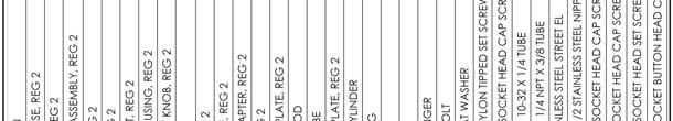
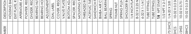
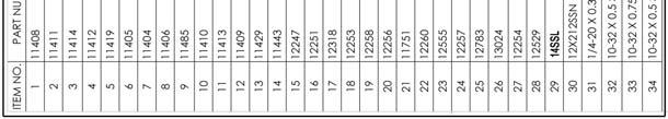
9 AccuStream Cutting Systems 7 3 Drawings and Parts Lists
ABRASIVE REGULATOR II
 ABRASIVE REGULATOR II 13096 Abrasive Regulator II TABLE OF CONTENTS 1 Introduction... 1 2 Abrasive Regulator... 2 2.1 Regulator Installation... 2 Location... 2 Attaching the Regulator to the Machine...
ABRASIVE SYSTEM ABRASIVE REGULATOR II 800# BULK ABRASIVE DELIVERY POT Abrasive Regulator II and 800# Pot Manual
 ABRASIVE SYSTEM ABRASIVE REGULATOR II 800# BULK ABRASIVE DELIVERY POT TABLE OF CONTENTS Contact Information and Customer & Technical Service... 1 1 Introduction... 1 2 Abrasive Regulator... 1 Description:...
HORIZONTAL BLADDER TANK
 Balanced Pressure Proportioning System Reliable Foam System Requiring Only Water Power Perfect For Low Ceilings UL Listed, ASME, National Board Registered Bladder-UL162 Approved, High Tensile Pressure
VERTICAL BLADDER TANK
 Balanced Pressure Proportioning System Reliable Foam System Requiring Only Water Power Perfect For Tight Spaces UL Listed, ASME, National Board Registered Bladder-UL162 Approved, High Tensile Pressure
Pressure Dump Valve Service Kit for Series 3000 Units
 Instruction Sheet Pressure Dump Valve Service Kit for Series 000 Units. Overview The Nordson pressure dump valve is used to relieve hydraulic pressure instantly in Series 00, 400, 500, and 700 applicator
Chemical Injection Technologies Installation/Service Bulletin
 Bulletin 4002 Chemical Injection Technologies Installation/Service Bulletin SUPERIOR Series CL-16/26/56 Automatic Switchover Gas Chlorinator - Installation & Operation IMPORTANT!! READ THESE PRECAUTIONS
Halsey Taylor Owners Manual 4410 Freeze Resistant Tubular Fountain STOP!
 Halsey Taylor Owners Manual 4410 Freeze Resistant Tubular Fountain STOP! PLEASE READ THE FOLLOWING INFORMATION. ITALLATION ITRUCTIO FOR THE 4410FR FTN. WITH 97243C SINGLE VALVE CONTROL ASSEMBLY ARE LOCATED
Halsey Taylor Owners Manual STOP!
 Halsey Taylor Owners Manual 4710 Freeze Resistant Floor Mounted Steel Fountain STOP! PLEASE READ THE FOLLOWING INFORMATION. ITALLATION ITRUCTIO FOR THE 4710FR FTN. WITH 97243C SINGLE VALVE CONTROL ASSEMBLY
Installation of Your SprayMaster System
 Installation of Your SprayMaster System 1. At the installation site, remove all equipment from the corrugated box and the polyethylene drum and replace the drum lid. Check the picture to identify each
COMPACT TRIPLE WALL OUTLET STATION MODEL INSTALLATION AND OPERATING INSTRUCTIONS
 COMPACT TRIPLE WALL OUTLET STATION MODEL 6255-1 INSTALLATION AND OPERATING INSTRUCTIONS To assure safe operation and conformation to local fire codes, all Porter Outlet Stations are designed to be used
Pressure Dump Valve Service Kit for Series 2300 Units
 Instruction Sheet Pressure Dump Valve Service Kit for Series 00 Units. Overview The Nordson pressure dump valve is used to relieve hydraulic pressure instantly in Series 00 applicator tanks when the unit
Instruction Manual - Diaframless TM Ejector Chlorine, Sulfur Dioxide and Ammonia
 Instruction Manual - Diaframless TM Ejector Chlorine, Sulfur Dioxide and Ammonia - 1-122.6010.6 These instructions describe the installation, operation and maintenance of the subject equipment. Failure
PRO SINK -R 1 and 2. Dilution system CONTENTS
 PRO SINK -R 1 and 2 Dilution system CONTENTS 1.0 Product description 2 2.0 Warnings.. 3 3.0 Installation procedure 4 4.0 Plumbing connections 4 5.0 Technical features.. 5 6.0 Maintenance... 6 7.0 Troubleshooting......6
Instruction Manual O-Ring Ejector Chlorine & Sulfur Dioxide to 500 PPD (10 kg/h)
") Instruction Manual O-Ring Ejector Chlorine & Sulfur Dioxide to 500 PPD (10 kg/h) 100 PPD (2 kg/h) Maximum 250 PPD (5 kg/h) Maximum 500 PPD (10 kg/h) Maximum - 1-122.6006.9 These instructions describe the
Instruction Manual O-Ring Ejector Chlorine & Sulfur Dioxide to 500 PPD (10 kg/h) 100 PPD (2 kg/h) Maximum 250 PPD (5 kg/h) Maximum 500 PPD (10 kg/h) Maximum - 1-122.6006.9 These instructions describe the
MAYHEM MAYHEM OWNERS MANUAL. Paintball Guns International. Manufactured by
 MAYHEM MAYHEM OWNERS MANUAL Manufactured by Paintball Guns International Table of Contents Specifications...................... 2 Parts diagram and Listing............. 3 Description of Marker Operation.......
User s Guide. Vacuum Controller for liquid delivery systems
 Flow Control User s Guide Vacuum Controller for liquid delivery systems Precise Vacuum Control throughout the experiment Flow control Compatible with any perfusion system Ideal for Small Volume Delivery
OPERATION MANUAL NTF-15
 OPERATION MANUAL NTF-15 Nitrogen Tire Filling Valve Stem Caps (Qty=200) Order P/N 436075 RTI Technologies, Inc 10 Innovation Drive York, PA 17402 800-468-2321 www.rtitech.com 035-81235-00 (Rev B) TABLE
O P E R ATING INSTRUCTIONS FOR MODEL SPR-45 Automatic Screen and Stencil Printer
 O P E R ATING INSTRUCTIONS FOR MODEL SPR-45 Automatic Screen and Stencil Printer TABLE OF CONTENTS I. SPECIFICATIONS...3. II. SAFETY INSTRUCTIONS...4. III. INSTALLATION...5. IV. SET-UP...6. V. SYSTEM OPERATION...9.
User Instruction Manual
 User Instruction Manual 4500 psi Air Compressor Ver 2, 1.18 Contents Parts Included...3 Assembly Instructions...3-5 Operation Instructions...6-7 Oil Change Intervals...8 Air Filter Replacement...9 Setting
P5513. Users Manual. Pneumatic Comparison Test Pump. Test Equipment Depot Washington Street Melrose, MA TestEquipmentDepot.
 Test Equipment Depot - 800.517.8431-99 Washington Street Melrose, MA 02176 TestEquipmentDepot.com P5513 Pneumatic Comparison Test Pump Users Manual PN 3963372 November 2010 2010 Fluke Corporation. All
Nitrous Oxide / Oxygen FLOOR MOUNTED OUTLET STATION Installation and Instructions
 FM-171 Rev. B 8/00 Nitrous Oxide / Oxygen FLOOR MOUNTED OUTLET STATION Installation and Instructions MODEL 6300-1 PORTER INSTRUMENT COMPANY, INC. 245 TOWNSHIP LINE RD. P.O. BOX 907 HATFIELD, PA 19440-0907
Hi-Force Limited Prospect Way Daventry Northants NN11 8PL United Kingdom Tel: +44(0) : Fax: +44(0) : Website:
 : Fax: +44(0) : Website:") 1.0 Inspection of the product upon receipt: On receipt of the product, visually inspect the item for any evidence of shipping damage. Please note shipping damage is not covered by warranty. If shipping
1.0 Inspection of the product upon receipt: On receipt of the product, visually inspect the item for any evidence of shipping damage. Please note shipping damage is not covered by warranty. If shipping
LNG Regulator Test Kit
 OVERVIEW Chart provides a LNG Economizer/Regulator Test Kit to help save money and time by allowing a technician to more accurately and easily diagnose the operability of the pressure control regulator/economizer
BS2000 MOTOR ELECTRONICS, INC. PROTECTION INSTRUCTION MANUAL. (407) Phone: Website:
 Phone: Website:") BS2000 INSTRUCTION MANUAL MOTOR PROTECTION ELECTRONICS, INC. 2464 Vulcan Road Apopka, Florida 32703 Phone: Website: (407) 299-3825 www.mpelectronics.com Revision Date: 6-23-14 RECOMMENDED REPLACEMENT
BS2000 INSTRUCTION MANUAL MOTOR PROTECTION ELECTRONICS, INC. 2464 Vulcan Road Apopka, Florida 32703 Phone: Website: (407) 299-3825 www.mpelectronics.com Revision Date: 6-23-14 RECOMMENDED REPLACEMENT
INSTALLATION INSTRUCTIONS. CVS 67CFR Pressure Reducing Instrument Supply Regulator INTRODUCTION
 INSTALLATION INSTRUCTIONS CVS 67CFR Pressure Reducing Instrument Supply Regulator INTRODUCTION The CVS Controls 67CFR Filter regulator is a pressure reducing supply regulator typically used for pneumatic
OPERATING AND MAINTENANCE MANUAL
 Series 4300 Engineered Performance TABLE OF CONTENTS 0 INTRODUCTION 1 1 Scope 1 2 Description 1 3 Specifications 1 0 INSTALLATION 1 1 Mounting 1 2 Piping 1 1 Connecting Process Pressure 2 2 Vent Connections
APPS-160 Gen 2 User Manual
 APPS-160 Gen 2 User Manual Applicable Products: PN 11914406 - APPS-160 10 to 50 PSIG operating pressure PN 11918618 - APPS-160 40 to 85 PSIG operating pressure Rev 9/16/2004 Chart Ind. www-chart-ind.com
VOLUMATIC WATER REGULATOR
 Introduction The Chore-Time VOLUMATIC regulator is designed to regulate water pressure for Chore-Time Layer and Brood Grow Nipple Watering Systems. There is a model for manual adjustment of the regulator
Operation Manual - PN A MENSOR MODEL 73 SHOP AIR BOOSTER
 Operation Manual - PN 0017946001 A MENSOR MODEL 73 SHOP AIR BOOSTER Mensor Model 73 Shop Air Booster System (750 psi Version) April 23, 2012 Trademarks / Copyright Mensor is a registered trademark of Mensor
Introduction. Part one: Identify the Hydraulic Trainer Components
 The University Of Jordan School of Engineering Mechatronics Engineering Department Fluid Power Engineering Lab Experiments No.4 Introduction to Hydraulic Trainer Objective: Students will be able to identify
NTF-515. Operation Manual
 NTF-515 Operation Manual RTI Technologies, Inc. 10 Innovation Drive York, Pennsylvania 17402 USA Phone: 717-840-0678 Toll Free: 800-468-2321 Web-site: www.rtitech.com Manual P/N: 035-81474-00 (RevA) TABLE
RhinoPro Cartridge Gun Manual
 RhinoPro Cartridge Gun Manual RhinoPro Cartridge Gun 1500 with 750ml cartridges Table of Contents Application Instructions......................................... 1 Operating Instructions..........................................
Models: C62/63/64-A/D
 Installation & Service C62-991-24A3 Models: C62/63/64-A/D Diaphragm Bypass Pressure Regulating Valves IMPORTANT Record your pump model number and serial number here for easy reference: Model No. Serial
Combination Air Valve Model
 Combination Air Valve Model Model C10 /C11 Installation, Operation and Maintenance Manual (IOM) Table of Contents General...Page 2 Safety...Page 2 Operational Data...Page 3 Materials and Connections...Page
NHR Powder Feed Hopper
 Instruction Sheet P/N 0804A0 NHR-8-50 Powder Feed Hopper Description This instruction sheet provides specifications, installation and operation instructions, and parts lists for the NHR-8-50 powder feed
TABLE OF CONTENTS SAFETY FIRST!...3 BASIC OPERATION...4 ADJUSTMENTS...5. Cocking Pressure...5. Three-Way Valve Adjustment...6
 TABLE OF CONTENTS SAFETY FIRST!...3 BASIC OPERATION...4 ADJUSTMENTS...5 Cocking Pressure...5 Three-Way Valve Adjustment...6 External Three-Way adjustment...6 In-Line Regulator...6 Ram to Cocking Block
FIRESTORM. Assembly Instructions. Electric Upgrade Kit for the Autococker. Designed & Manufactured by PGI
 FIRESTORM Electric Upgrade Kit for the Autococker Assembly Instructions Designed & Manufactured by PGI Table of Contents Introduction 1 Safety 1 Parts Diagram 2 Parts Diagram Listing 2 Getting Started
Freedom8 ShoeBox Compressor Manual
 Freedom8 ShoeBox Compressor Manual Warning!! This product is not a toy! Use or misuse can cause severe injury or death! Use only with adult supervision. This unit is only to be used with tanks, hoses and
INDUSTRIAL VALVES MODELS: C62-A; C62-D. INSTRUCTION MANUAL Installation Operation Parts Service DIAPHRAGM BYPASS PRESSURE REGULATING VALVES
 INSTRUCTION MANUAL Installation Operation Parts Service IMPORTANT Record your Regulator model number and serial number here for easy reference: Model No. Serial No. Date of Purchase When ordering parts
INSTALLATION INSTRUCTIONS MANUAL ON/OFF SAFETY VALVE/PILOT KIT MODEL GA9050A-1 (F0235)
") P/N 126905-01 Rev. B 11/2016 INSTALLATION INSTRUCTIONS MANUAL ON/OFF SAFETY VALVE/PILOT KIT MODEL GA9050A-1 (F0235) For All Single, Dual and Triple Burner Natural and Propane/LP Gas Logs P126905-01 For
P/N 126905-01 Rev. B 11/2016 INSTALLATION INSTRUCTIONS MANUAL ON/OFF SAFETY VALVE/PILOT KIT MODEL GA9050A-1 (F0235) For All Single, Dual and Triple Burner Natural and Propane/LP Gas Logs P126905-01 For
OPERATION MANUAL NTF-60 Plus
 OPERATION MANUAL NTF-60 Plus Nitrogen Tire Filling Valve Stem Caps (Qty=200) Order P/N 436075 RTI Technologies, Inc 10 Innovation Drive York, PA 17402 800-468-2321 www.rtitech.com 035-81264-00 (Rev A)
FOR INSTALLING CO 2 BLENDER KIT (P/N IN BEER SYSTEM
 IMI CORNELIUS INC One Cornelius Place Anoka, MN 55303-623 Telephone (800) 238-3600 Facsimile (612) 22-326 INSTALLATION INSTRUCTIONS FOR INSTALLING CO 2 BLENDER KIT (P/N 111612000 IN BEER SYSTEM SECONDARY
Rejuvenation Instructions
 Rejuvenation Instructions #401 Air Systems UPR This NRI covers the following: Understanding the applications and operation of flow meters. Understand the application and operation of test pressure gauges.
PAGE (Rev. A - 06/17)
") Owners Manual Models 4420BF1UDBFR* and 4420BF1LDBFR* Bi-Level Tubular Bottle Filler Fountain with Pet Fountain and Sanitary Freeze Resistant Triple Valve Control Assembly MODEL (LK)4420BF1UDBFR MODEL (LK)4420BF1LDBFR
Owners Manual Models 4420BF1UDBFR* and 4420BF1LDBFR* Bi-Level Tubular Bottle Filler Fountain with Pet Fountain and Sanitary Freeze Resistant Triple Valve Control Assembly MODEL (LK)4420BF1UDBFR MODEL (LK)4420BF1LDBFR
256 Pneumatic Pressure Indicator
 256 Pneumatic Pressure Indicator 51425699 Copyright 2002 Slope Indicator Company. All Rights Reserved. This equipment should be installed, maintained, and operated by technically qualified personnel. Any
JARVIS. Model CPE Hock and Neck Cutter EQUIPMENT... TABLE OF
 74 Hock and Neck Cutter EQUIPMENT SELECTION... Ordering No. TABLE OF CONTENTS... Page with Control Circuit. 4304003 only... 4304004 Balancer... 1350084 Control Circuit... 3350010 Air Hose (Yellow)... 3323003
Technical Bulletin. Parts and Service News. LPG Lock-Off valve replacement procedures for 4.2 Liter Ford V6
 Equipment Affected Technical Bulletin LPG Lock-Off valve replacement procedures for 4.2 Liter Ford V6 Ford 4.2L V-6 powered tractors with LPG fuel systems. Part Description Discrepancy Fuel Pressure Lock-off
WARNING: READ THE GENERAL INFORMATION MANUAL INCLUDED FOR OPERATING AND SAFETY PRECAUTIONS AND OTHER IMPORTANT INFORMATION.
 GSR500 Ram Assembly General Description The GSR500 single post lift / ram uses a 3-1/4 air powered cylinder, which is welded to a heavy gauge base. It is normally used to raise and lower a fluid handling
Combination Air Valve
 Combination Air Valve For Sewage and Wastewater Model C50 Installation, Operation and Maintenance Manual (IOM) Table of Contents General... Page 2 Safety... Page 2 Operational Data... Page 3 Materials
Instruction Manual Updated 7/26/2011 Ver. 2.2
 4-Unit Model MB HTHP Filter Press #171-50-4: 115-Volt #171-51-4: 230-Volt Instruction Manual Updated 7/26/2011 Ver. 2.2 OFI Testing Equipment, Inc. 11302 Steeplecrest Dr. Houston, Texas 77065 U.S.A. Tele:
CHECK-VALVES Automatically Position Themselves by the Natural Forces of the Conveying Air. A PNEUMATIC CONVEYING SYSTEM PATENT #: 5,160,222
 PATENT #: 5,160,222 PHONE: (913)677-5777 FAX: (913)677-067 E-Mail : techair@techairinc.com www.techairinc.com CHECK-KLEEN DIVERTER A PNEUMATIC CONVEYING SYSTEM FLAP-CHECKS exposed to product air stream
RD(H)20/25 Pressure-Reducing Regulator User Manual
20/25 Pressure-Reducing Regulator User Manual") RD(H)20/25 Pressure-Reducing Regulator User Manual Read the complete manual before installing and using the regulator. 2 Safe Product Selection When selecting a product, the total system design must be
RD(H)20/25 Pressure-Reducing Regulator User Manual Read the complete manual before installing and using the regulator. 2 Safe Product Selection When selecting a product, the total system design must be
Types 749B and R130 Changeover Manifolds
 Instruction Manual MCK-1179 Types 749B and R130 June 2012 Types 749B and R130 Changeover Manifolds TYPE HSRL-749B TYPE 64SR/122 TYPE R130/21 TYPE 749B/21 Figure 1. Changeover Manifolds and Regulator Assemblies
FLUSHMATE III FLUSHMATE FLUSHOMETER - TANK SYSTEM. Owner s Service Manual. 503 Series. 503 Series
 Owner s Service Manual 503 Series FLUSHMATE III FLUSHOMETER - TANK SYSTEM 503 Series FLUSHMATE A Division of Sloan Valve Company 30075 Research Drive New Hudson, MI 48165 800-533-3450 248-446-5300 http://www.flushmate.com
SINORIX Valve Reconditioning
 Document No. 129-097 SINORIX Valve Reconditioning Product Description These instructions explain how to recondition and fill 1-inch through 4-inch SINORIX valves. Product Numbers Verify that the appropriate
Section 3- Repair and Calibration Procedures
 Section 3- Repair and Calibration Procedures 1. Refrigerant Removal Procedures 2. Scale/PC Board Recalibration Procedure 3. PC Board Configuration Procedure of AR400 4. Scale Tare Procedure 5. Gauge Calibration
BioAerosol Nebulizing Generator. Operation and Maintenance User Manual
 BioAerosol Nebulizing Generator Operation and Maintenance User Manual INTRODUCTION The BANG or BioAerosol Nebulizing Generator is a unique nebulizer for the generation of aqueous aerosols at a low air
Binks SG-2 Plus TM 2 QT. PRESSURE CUPS Model No (Standard) Model No (with OscillatingAgitator)
 Model No (with OscillatingAgitator)") INTRODUCTION Binks SG-2 Plus TM Pressure Cup is ideal for component spraying and industrial applications where small batch production spraying is required. The 2 qt. capacity is sufficient to complete
INTRODUCTION Binks SG-2 Plus TM Pressure Cup is ideal for component spraying and industrial applications where small batch production spraying is required. The 2 qt. capacity is sufficient to complete
Blue River Technologies Port-A-Poly Mixer w/2.5 GPH LMI Pump And Secondary Water Dilution Line INSTALLATION AND OPERATION
 Blue River Technologies Port-A-Poly Mixer w/2.5 GPH LMI Pump And Secondary Water Dilution Line INSTALLATION AND OPERATION Install your Blue River Technologies Port-A-Poly mixing system in a clean dry area.
! WARNING! IMPORTANT HPA AIR TANK SAFETY INSTRUCTION AND GUIDELINES ! WARNING! IMPORTANT SAFETY INSTRUCTION AND GUIDELINES
 ! WARNING! IMPORTANT SAFETY INSTRUCTION AND GUIDELINES! WARNING! IMPORTANT HPA AIR TANK SAFETY INSTRUCTION AND GUIDELINES This Paintball Marker is NOT A TOY. Misuse can cause serious injury or death. It
TEST SPECIFICATION NYT-909-C
 748 Starbuck Ave, Watertown, NY 13601 Phone: +1-315-786-5200 Engineering Fax: +1-315-786-5673 TEST SPECIFICATION NYT-909-C CODE OF TESTS FOR TESTING "AB" TEST RACK P/N 702546 & 702612 ISSUE NO. 5 1.0 THE
Powermax machine-side reference guide For mechanized applications with Powermax1000, Powermax1250 and Powermax1650
 Powermax machine-side reference guide For mechanized applications with Powermax1000, Powermax1250 and Powermax1650 This Powermax machine-side reference guide is a supplement to your Operator Manual and
BLAST-IT-ALL. TOLL FREE: (800)
") BLAST-IT-ALL TOLL FREE: (800) 535-2612 sales@blast-it-all.com www.blast-it-all.com BLAST-IT-ALL TOLL FREE: (800) 535-2612 sales@blast-it-all.com www.blast-it-all.com MICROVALVE The MicroValve gives you
BLAST-IT-ALL TOLL FREE: (800) 535-2612 sales@blast-it-all.com www.blast-it-all.com BLAST-IT-ALL TOLL FREE: (800) 535-2612 sales@blast-it-all.com www.blast-it-all.com MICROVALVE The MicroValve gives you
ATD LB PRESSURE BLASTER INSTRUCTION MANUAL
 ATD-8402 90LB PRESSURE BLASTER INSTRUCTION MANUAL SAVE THESE INSTRUCTIONS SAFETY INSTRUCTIONS FOR SANDBLASTER 1. Before opening the tank release the air pressure on the sand tank. To do this, turn off
UltRo Dual Flow Reverse Osmosis Water System
 UltRo Dual Flow Reverse Osmosis Water System Congratulations on this great investment to your health. **IMPORTANT NOTE BEFORE YOU BEGIN** We recommend you call your local friendly plumber to ensure proper
Welker Sampler. Model GSS-1. Installation, Operation, and Maintenance Manual
 Installation, Operation, and Maintenance Manual Welker Sampler Model GSS-1 The information in this manual has been carefully checked for accuracy and is intended to be used as a guide to operations. Correct
Tribomatic II Powder Pump
 Instruction Sheet P/N Tribomatic II Powder Pump WARNING: Allow only qualified personnel to perform the following tasks. Follow the safety instructions in this document and all other related documentation.
Carbon Fiber Tank with EZ Fill system Fill pressure 4,500 psi (310 bar) Output: up to 4,500 psi (310 bar)
 Output: up to 4,500 psi (310 bar)") Carbon Fiber Tank with EZ Fill system Fill pressure 4,500 psi (310 bar) Output: up to 4,500 psi (310 bar) Ver 1, 10/18 Contents Safety System...3 Filling The Air Venturi Ez Fill System...4 Micro Bore Hose
Carbon Fiber Tank with EZ Fill system Fill pressure 4,500 psi (310 bar) Output: up to 4,500 psi (310 bar) Ver 1, 10/18 Contents Safety System...3 Filling The Air Venturi Ez Fill System...4 Micro Bore Hose
Medical Gas Control Panel
 Medical Gas Control Panel INSTALLATION & MAINTENANCE MANUAL 255105 (Rev. 6) 2018-04 2 255105 (Rev. 6) 2018-04 1.0 User Responsibilities The information contained in this installation and operation maintenance
Assembly Drawing: W-311B-A01, or as applicable Parts List: W-311B-A01-1, or as applicable Special Tools: , , &
 REDQ Regulators Model 411B Barstock Design Powreactor Dome Regulator OPERATION AND MAINTENANCE Contents Scope..............................1 Installation..........................1 General Description....................1
Helium-Oxygen Blender
 Helium-Oxygen Blender Service Manual Model No. PM5400 Series PM5500 Series (shown) SAVE THESE INSTRUCTIONS 300 Held Drive Tel: (+001) 610-262-6090 Northampton, PA 18067 USA Fax: (+001) 610-262-6080 www.precisionmedical.com
DISPENSING VALVE MODEL VDP100 INSTRUCTION MANUAL
 DISPENSING VALVE MODEL VDP100 INSTRUCTION MANUAL CONTENTS 1. Safety - - - - - - - - - - - - - - - - - - - - - - - - - 3 2. Introduction - - - - - - - - - - - - - - - - - - - - - - - - - 5 3. Specification
User s Guide. Pressure Controller for liquid delivery systems
 Flow Control User s Guide Pressure Controller for liquid delivery systems Precise Pressure Control throughout the experiment Flow control Compatible with any perfusion system Ideal for Small Volume Delivery
NTF-230 OPERATION MANUAL
 NTF-230 OPERATION MANUAL MAHLE Aftermarket Inc., Service Solutions 10 Innovation Drive York, Pennsylvania 17402 USA Phone: 717-840-0678 Toll Free: 800-468-2321 Web-site: www.servicesolutions.mahle.com
VRS Assembly & Operating Instructions
 VRS Assembly & Operating Instructions Models VRS-18 Pn #270003 VRS-24 Pn #270006 VRS-30 Pn #270010 Not for use on pressure vessels equipped with Automatic exhaust valve (680 controls) EMPIRE ABRASIVE EQUIPMENT
INSTALLATION INSTRUCTIONS
 COUNTER-CURRENT SWIMMING Hurricane Turbo Swim Jet INSTALLATION INSTRUCTIONS PACKET NO.1 With a COUNTER-CURRENT SWIMMING device your swimming pool is no longer a simple man-made lake. It becomes the most
CO2 Tank Conversion Kit P.N , P.N , and P.N
 Foodservice Group Multiplex Beverage Equipment Installation Instructions for CO2 Tank Conversion Kit P.N. 002247, P.N. 0022505, and P.N. 0025099 Introduction The following instructions cover the installation
Compact Triple Cabinet Outlet Station Model Installation and Operating Instructions
 Compact Triple Cabinet Outlet Station Model 6258-1 Installation and Operating Instructions The Porter Compact Triple Outlet Station (6258-1) provides a quick, safe, and reliable method of connection to
BRAKE SYSTEM BLEEDING
 BRAKE SYSTEM BLEEDING 1988 Jeep Cherokee 1988 BRAKES Jeep - Brake System Bleeding Cherokee, Comanche, Grand Wagoneer, Wagoneer, Wrangler BRAKE SYSTEM BLEEDING Hydraulic system bleeding is necessary any
OWNER S MANUAL. Dual Chamber Blast Machine. for 1 to 4 operators. with pneumatic. metering- and air valves
 OWNER S MANUAL Dual Chamber Blast Machine for 1 to 4 operators with pneumatic metering- and air valves Clemco International GmbH Carl-Zeiss-Straße 21 Tel.: +49 (0) 8062 90080 83052 Bruckmühl Mail: info@clemco.de
Tri-Mode Tumblebox O&M Manual
 Tri-Mode Tumblebox O&M Manual Air Side Tri-Mode Valve Part #60-070-012 Water Side w w w. a d v a n c e d p r e s s u r e s y s t e m s. c o m 701 S. Persimmon, Suite 85 - Tomball, Texas 77375 YOU ARE RESPONSIBLE
MEDICAL EQUIPMENT CATALOG
 THE MOST TRUSTED MEDICAL EQUIPMENT IN NORTH AMERICA MEDICAL EQUIPMENT CATALOG Total Components Including Bulk Oxygen Supply, Back up and Delivery Equipment Designs for High Pressure, Liquid or Bulk Applications
DBML-60/80 Squeeze Tool
 DBML-60/80 Squeeze Tool OPERATORS MANUAL Description The Mustang Model DBML-60/80 Hydraulic squeeze tool has been manufactured since 1995. A Mustang 3 3/4 bore doubleacting cylinder producing 41,000 lbs
Tridak Model 1060 User Guide. Syringe Filling System
 Tridak Model 1060 User Guide Syringe Filling System 2 Model 1060 Syringe Filler User Guide About Dymax Light-curable materials as well as systems for light curing, fluid dispensing, and fluid packaging.
Techcon Systems TS1258 Pressure Pot
 Techcon Systems TS1258 Pressure Pot User Guide TABLE OF CONTENT 1. SAFETY. 3 1.1 Intended Use 3 1.2 Safety Precaution 3 2. CERTIFICATE OF COMFORMANCE 4 3. FEATURES. 5 4. SPECIFICATIONS 5 5. INSTALLATION
INSTRUCTION MANUAL. January 23, 2003, Revision 0
 INSTRUCTION MANUAL Model 810A In-Vitro Test Apparatus for 310B Muscle Lever January 23, 2003, Revision 0 Copyright 2003 Aurora Scientific Inc. Aurora Scientific Inc. 360 Industrial Parkway S., Unit 4 Aurora,
IMPORTANT PLEASE READ BEFORE COMMENCING INSTALLATION
 IMPORTANT PLEASE READ BEFORE COMMENCING INSTALLATION This Fitting Guide is designed to assist in the Installation of your Reverse Osmosis System. Some of the parts that are supplied with each system may
SERVICE MANUAL SALAMANDER BROILERS RADIANT AND INFRARED 36RB 36IRB VULCAN C36RB C36IRB WOLF
 SERVICE MANUAL SALAMANDER BROILERS RADIANT AND INFRARED VULCAN 36RB 36IRB WOLF C36RB C36IRB This Manual is prepared for the use of trained Vulcan Service Technicians and should not be used by those not
Installation Instructions
 Installation Instructions COLONY SOFT 7.0 Centerset Lavatory Faucet 7.0 with Speed Connect Drain Congratulations on purchasing your American Standard faucet with the Speed Connect drain, a features found
2.0 INSTALLATION & SERVICE
 Installation, Operation, and Maintenance Instructions MODEL 5600 / 5600R January 2005 CONTENTS 1.0 GENERAL 1.1 5600 Model Number Information -----------------------------------------------------------------------
HPIC D Hydrostatic Test Pump PRODUCT INFORMATION AND OPERATING INSTRUCTIONS
 WIDDER TOOLS HPIC-10000-D Hydrostatic Test Pump PRODUCT INFORMATION AND OPERATING INSTRUCTIONS Description: The WIDDER Hydrostatic Test Systems C Series is a portable, selfcontained, air driven hydrostatic
!!!! SERVICE MANUAL PRESSURE POT 2 GALLON. Service Manual: LT Washington St 931 Progress Ave., #7
 EXEL North America, Inc. EXEL Industrial Canada, Inc. 1310 Washington St 931 Progress Ave., #7 West Chicago, IL 60185 Scarborough ONT, M1G 3V5 Ph : (800) 573 5554 Ph : (800) 450 0655 Fx : (800) 664 1511
CART FOR CENTURION 1500+
 CART FOR CENTURION 1500+ Operation & Maintenance Manual www.ameriwater.com 800-535-5585 AmeriWater 3345 Stop 8 Rd. Dayton, OH 45414 98-0161 Rev A Contents 1. GENERAL INFORMATION... 1 1.1. Features...
Discontinued. Powers Controls. Technical Instructions Document No P25 RV Rev. 1, May, RV 201 Pressure Reducing Valves.
 Powers Controls RV 201 Pressure Reducing Valves Description Features Product Numbers Dual Pressure PRV Technical Instructions Document No. 155-049P25 RV 201-1 Single Pressure PRV The RV 201 Pressure Reducing
4 IN. BALL LAUNCHER Engine Mounted / PTO Driven
 4 IN. BALL LAUNCHER Engine Mounted / PTO Driven OPERATOR S PARTS and MAINTENANCE MANUAL 2006 EDITION BL-MAN-4EN Creation Revision date: 10MAR06 date: by: Ivon LeBlanc by: Table of Contents Table of Contents...
Inflatable Packer Single & Double. Single & Double Packer Dimension. Wireline Packer. Water Testing Packer (WTP) Packer
 Packer") Inflatable Packer Single & Double Single & Double Packer Dimension Wireline Packer Water Testing Packer (WTP) Packer Packer Working Pressure & Depth Chart Packer Water Hand Pump Packer Air Driven Pump
Inflatable Packer Single & Double Single & Double Packer Dimension Wireline Packer Water Testing Packer (WTP) Packer Packer Working Pressure & Depth Chart Packer Water Hand Pump Packer Air Driven Pump
Installation and Use Manual
 Installation and Use Manual EMASMB & LMASMB Surface Mount Bottle Filling Stations Model EMASMB IMPORTANT THIS IS AN INDOOR APPLICATION ONLY! ALL SERVICE TO BE PERFORMED BY AN AUTHORIZED SERVICE PERSONNEL.
SUMMITTM 400 & 600. Natural Gas Barbecues. Step-By-Step Guide
 SUMMITTM 400 & 600 Natural Gas Barbecues Step-By-Step Guide W E B E R W E B E R W E B E R W E B E R Summit 400 NG Summit 600 NG CANADIAN GAS ASSOCIATION R A P P R O V E D WARNING: Follow all leak check
Adjustable. Unloader Valve. O&M Manual. Part #
 Adjustable Unloader Valve O&M Manual Unloader Valve Part #60-020-361 ADVANCED PRESSURE SYSTEMS 701 S. Persimmon St., Suite 85 - Tomball, TX 77375 Toll Free in North America: (877) 290-4277 Phone: (281)
INSTALLATION and OPERATION INSTRUCTIONS
 INSTALLATION and OPERATION INSTRUCTIONS FLOJET Beer Pump Panels MODEL NO. 66134-1 66134-2 66134-3 66134-4 IMPORTANT INFORMATION This manual has been prepared to assist you in the operation of Perlick Beer