I International Bureau (10) International Publication Number (43) International Publication Date
|
|
|
- Warren Harrington
- 5 years ago
- Views:
Transcription
1 (12) INTERNATIONAL APPLICATION PUBLISHED UNDER THE PATENT COOPERATION TREATY (PCT) (19) World Intellectual Property Organization I International Bureau (10) International Publication Number (43) International Publication Date WO 2013/ Al 16 May 2013 ( ) P O P C T (51) International Patent Classification: (81) Designated States (unless otherwise indicated, for every C21D 1/63 ( ) C21D 11/00 ( ) kind of national protection available): AE, AG, AL, AM, C21D 1/64 ( ) F27D 15/02 ( ) AO, AT, AU, AZ, BA, BB, BG, BH, BN, BR, BW, BY, C21D 9/04 ( ) F27D 99/00 ( ) BZ, CA, CH, CL, CN, CO, CR, CU, CZ, DE, DK, DM, DO, DZ, EC, EE, EG, ES, FI, GB, GD, GE, GH, GM, GT, (21) International Application Number: HN, HR, HU, ID, IL, IN, IS, JP, KE, KG, KM, KN, KP, PCT/IB2012/ KR, KZ, LA, LC, LK, LR, LS, LT, LU, LY, MA, MD, (22) International Filing Date: ME, MG, MK, MN, MW, MX, MY, MZ, NA, NG, NI, 12 November 2012 ( ) NO, NZ, OM, PA, PE, PG, PH, PL, PT, QA, RO, RS, RU, RW, SC, SD, SE, SG, SK, SL, SM, ST, SV, SY, TH, TJ, (25) Filing Language: Italian TM, TN, TR, TT, TZ, UA, UG, US, UZ, VC, VN, ZA, (26) Publication Language: English ZM, ZW. (30) Priority Data: (84) Designated States (unless otherwise indicated, for every MI201 1A November ( ) IT kind of regional protection available): ARIPO (BW, GH, GM, KE, LR, LS, MW, MZ, NA, RW, SD, SL, SZ, TZ, (71) Applicant: DANIELI & C. OFFICINE MECCANICHE UG, ZM, ZW), Eurasian (AM, AZ, BY, KG, KZ, RU, TJ, S.P.A. [ΓΓ/ΙΤ]; Via Nazionale, 41, Buttrio (IT). TM), European (AL, AT, BE, BG, CH, CY, CZ, DE, DK, EE, ES, FI, FR, GB, GR, HR, HU, IE, IS, IT, LT, LU, LV, (72) Inventor: ANDREATTA, Daniele; Via Rore, 81/A, I- MC, MK, MT, NL, NO, PL, PT, RO, RS, SE, SI, SK, SM, Borso Del Grappa (IT). TR), OAPI (BF, BJ, CF, CG, CI, CM, GA, GN, GQ, GW, (74) Agents: CINQUANTINI, Bruno et al; Corso di Porta ML, MR, NE, SN, TD, TG). Vittoria 9, Milano (IT). (54) Title: COOLING TANK FOR RAILS [Continued on nextpage] (57) Abstract: A cooling tank for the thermal treat ment of a rail head provided with a structure compris ing a first volume (2), adapted to be filled with a cool ing fluid; a second volume (4), arranged above the first volume and communicating therewith, so that the fluid passes from the first to the second volume and the rail head to be thermally treated can be immersed therein; a partition plate (5) between first and second volume, provided with a single row of holes (6), preferably ar ranged at the center of the width of the second volume, for generating jets of cooling fluid from the first to the second volume; a pair of longitudinal bulkheads (7), arranged in said second volume perpendicular to the plate and symmetrically with respect to the single row of holes, adapted to direct the jets of fluid exiting from the holes vertically upwards o o Fig. 1
2 Declarations under Rule 4.17: w o 2013/ Al llll II II 11III III II II 11I I III I III II I II Published: as to applicant's entitlement to apply for and be granted with international search report (Art. 21(3)) a patent (Rule 4.1 7(H)) before the expiration of the time limit for amending the of inventorship (Rule 4.17(iv)) claims and to be republished in the event of receipt of amendments (Rule 48.2(h))
3 "COOLING TANK FOR RAILS" *********** Field of the invention The present invention relates to a cooling tank, in particular to a tank suitable for cooling rails in a thermal treatment plant of rail heads. Background art Several solutions are known in the prior art for the thermal treatment of rolled rails, in particular aimed to obtain the hardening of the rail head. Starting from a temperature higher than 600 C, rails are subjected to a quick cooling of the head either by the use of spray nozzles, which inject a cooling fluid (water, air or water mixed with air) on the rail head, or by the immersion of the head into a cooling tank containing a cooling liquid, for example water added with additive. Compared to the solution with spray nozzles, the use of the tank allows to obtain a greater cooling uniformity, in the direction of the rail length, and higher cooling rates. In order to further increase the thermal exchange inside the tank and thus speed up the treatment, some solutions of the prior art provide for jets of cooling liquid originating from holes located on the bottom of the tank and impinging the rail head immersed in the liquid: such jets increase the thermal exchange and accordingly the cooling rate. Such a solution is described in document GB619699, which discloses a tank provided with three rows of holes on the bottom, wherefrom the cooling liquid exits, adapted to create jets of liquid directed towards the immersed rail head. However, the above document provides that the rail head to be treated rests on a support, which represents a hindrance for the liquid exiting from the holes and deviates it on the two sides of the rail head. As a result, the central zone of the rail head is not impinged by such jets and thus undergoes a non-uniform cooling. Other solutions have been proposed to improve such cooling process, as disclosed for example in document JP , which provide for supporting the rail by the bottom thereof so as to not have any hindrances between the jets and the immersed rail head and treat it as uniformly as possible.
4 In particular, JP provides for three separate jets, within the bath, directed onto the three faces of the rail head. Another known solution is disclosed in document WO2010/133666A1 where a plurality of baskets occupies the upper part of the central volume of the tank, each basket comprising lower panels or deflectors and respective upper panels or deflectors. Lower and upper deflectors are reciprocally separated by a longitudinal element comprising a central plate provided with at least ten rows of nozzles and integrally fixed to two side plates. Said side plates are not coplanar with respect to the central drilled plate but are inclined downwards with respect to the plane defined by the central drilled plate by a predetermined angle, for example equal to The lower deflectors are completely above the delivery manifold when the baskets are fully inserted into the tank modules. Together with the inner walls of the central volume, the lower deflectors define first compartments below the drilled central plate. At each of said first compartments there is provided a same number of calibrated holes, defining two opposite rows of nozzles respectively provided on two opposite sides of the underlying portion of the longitudinal stretches of the delivery manifold. At the junctions between the drilled central plate and non-drilled side plates, above the drilled central plate, there are provided curvilinear walls, convex with respect to the longitudinal center line plane of the module; and the upper deflectors, transversal to said curvilinear walls, together with said curvilinear walls, define second compartments above the drilled central plate. A further known solution is disclosed in document US2009/200713A1 where two drilled plates are provided, with nozzles arranged on multiple rows which divide the cooling tank into three compartments, arranged one on top of the other. However, in all these solutions of the prior art, at the exit of the nozzles, the jets of cooling liquid, going progressively up towards the rail, unavoidably tend to enlarge, loosing speed accordingly, and to flit about, i.e. to alternately direct rightwards or leftwards with respect to the hypothetical impact point, causing a non-symmetrical and non-uniform thermal transfer. On the other hand, the rail head cannot be moved too close to the holes, located on the bottom of the tank, to preserve the treatment uniformity on the entire rail length and prevent the so-called "punctiform effect" which is due to the presence
5 of a determined pitch between the holes: a rail too close to the holes is not uniformly treated along the longitudinal axis since the rail head zones, located perpendicularly above the holes, undergo a greater cooling than the stretches located at the pitch between two consecutive holes. The need of providing a cooling tank that allows to overcome the above drawbacks is therefore felt. Summary of the invention The primary object of the present invention is to provide a cooling tank for the thermal treatment of the rail head which, by directing jets of cooling fluid, allows a particularly high cooling efficiency to be achieved with the same flow rate and other conditions. Another object of the invention is to provide a cooling tank that, with the same efficiency, allows a high thermal exchange uniformity to be obtained on the entire rail length, being able to increase the distance of the rail head from the bottom of the tank, so as to limit or eliminate the punctiform effect of the jets. Another object of the invention is to provide a cooling tank for rails that allows a wide range control of the rate at which the jets of cooling fluid arrive in the proximity of the rail head, thus controlling the cooling rate, increasing or decreasing it according to the needs and the treatments required by the rail. The present invention therefore aims to achieve the above objects by providing a cooling tank for the thermal treatment of a rail head by immersion which, according to claim 1, defines a longitudinal axis and comprises a volume adapted to be filled with a cooling fluid in which the rail head to be thermally treated can be immersed, said volume having a bottom, the tank being characterized in that the bottom is provided with a single row of nozzles only, arranged along said longitudinal axis and parallel to a symmetry plane of said volume, in order to generate jets of cooling fluid in said volume, and in that at least one pair of substantially reciprocally parallel longitudinal bulkheads is provided, arranged in said volume substantially perpendicular to said bottom and symmetrically with respect to said single row of nozzles, configured to direct upwards the jets of cooling fluid exiting the nozzles. With the introduction of the bulkheads it is advantageously possible to direct the
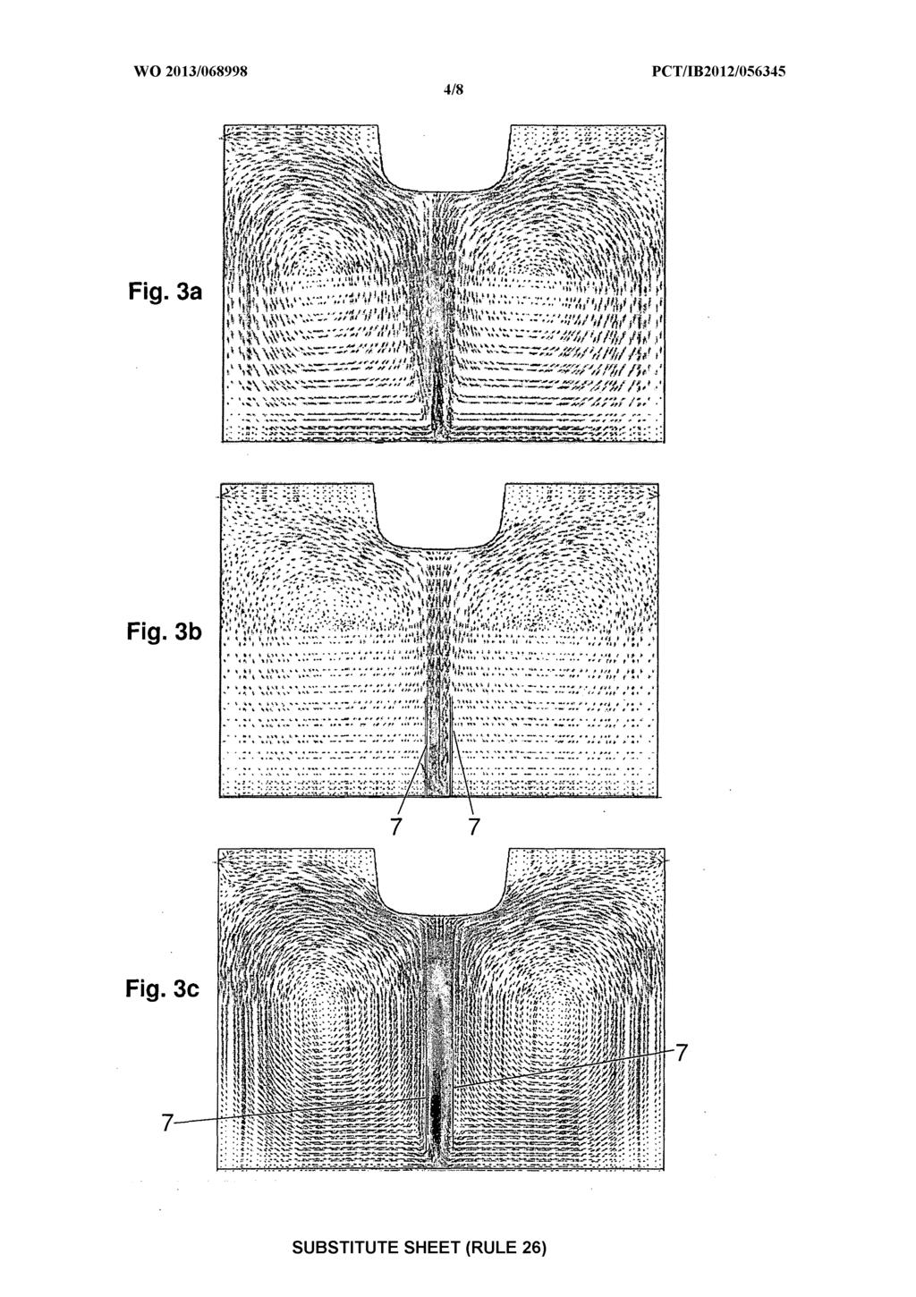
6 jets of fluid and drastically limit the flitting of the same: the single jet of cooling fluid impinges the center of the rail head and splits into two parts that symmetrically lap the two sides of the head. It has thus been seen that the presence of the bulkheads leads to greater cooling uniformity on the immersed section. Advantageously, with the bulkheads detached and lifted off the bottom of the tank, the fluid rate at the exit of the holes causes a suction of the surrounding fluid and a pulling of the fluid present at the sides of the holes or nozzles (ejector effect): a circular motion of the fluid is thus created at the sides of the bulkheads that is drawn from underneath the bulkheads and then proceeds aligned and with no flitting along a vertical direction, thanks to the presence of the bulkheads, towards the piece to be treated, to then continue on the sides of the same, cooling them. A part of the fluid then goes down again onto the bottom of the tank to be drawn again, passing underneath the bulkheads. Figures 3a, 3b and 3c compare the rate vectors of the cooling fluid at operating speed in the case of a tank without bulkheads (Fig. 3a), in the case of a tank according to the invention provided with bulkheads resting on the bottom of the tank (Fig. 3b) and, finally, in the case of a tank according to the invention provided with bulkheads spaced away from the bottom of the tank (Fig. 3c). From the comparison of figures 3a and 3b it is readily seen that the addition of the bulkheads makes the cooling fluid flow more compact, combined and coherent, substantially directional. If in the tank there are no bulkheads (Fig. 3a), the jet of fluid enlarges and already loses its compactness halfway between the exit nozzle and the rail head that must be treated. In particular, the jet becomes larger and slower accordingly, and splits into two parts even before reaching the center of the rail head. On the other hand, Figure 3c shows how the lifted bulkheads allow an even more stable and concentrated upward jet to be obtained. The gap between the bulkheads and the volume bottom allows, with the same rate of the jets exiting the holes, the involvement of a larger volume of cooling fluid and, thus, the achievement of high jet rates. High cooling rates may be achieved in this way, with the same flow rate and other conditions, without having to intervene on the chemical composition of the cooling fluid. This leads to a higher cooling
7 efficiency up to 50%. The presence of the bulkheads, either attached to or detached from the bottom of the tank, further allows the punctiform effect of the jets to be reduced on the rail length since it allows the distance between the rail head and the holes to be increased, with the same treatment efficiency. In fact, with the bulkheads it is possible to increase such distance up to completely eliminate the punctiform effect, thus obtaining the maximum longitudinal uniformity, still ensuring an adequate cooling efficiency. There is a continuous change of the liquid into the tank which, overflowing from the top of the same, is collected into two side volumes. Thanks to the present invention, the efficacy and flexibility of the thermal treatment process is increased since the tank allows even higher cooling fluid flow rates to be used. In fact, if the flow rate is increased without the use of bulkheads, the jets are characterized by a particularly chaotic and not very orderly movement and move away from the "working" zones, limiting the heat removal from the rail head. On the contrary, if the bulkheads are provided, even increasing the flow rate, the jet flow remains directional and is directed exactly towards the zone wherefrom heat must be removed. Thanks to the possibility of using higher flow rates, it is possible to achieve higher cooling rates, bringing an absolute increase in the cooling capacity to over 50%. In this way, the operating range of the tank is increased from 1 to 20 C/sec, preferably from 1.5 to 15 C/sec without having to modify or replace the type or concentration of hardening solution used. This leads to a high operating flexibility of the tank, with considerable advantages for the end user in terms of management (storage, filling, disposal) of the hardening solution according to the type of product to be treated. The distance between the two bulkheads affects the treatment efficiency: increasing the distance between the two bulkheads, the jet rate decreases, accordingly dropping the cooling rate; the contrary happens if said distance is decreased. An advantageous variant of the cooling tank of the invention provides for a system for adjusting the bulkhead position (either manual or automatic) in order to adjust
8 said distance between the two bulkheads and/or said gap from the bottom of the tank when provided, so as to change the cooling rate without modifying the cooling fluid flow rate. The cooling tank according to the invention has the following advantages: - the flitting of the jets of cooling fluid exiting the holes is drastically reduced; - the fluid jet can be directed towards the center of the rail head; - a symmetrical treatment is obtained with respect to the symmetry plane of the rail cross section; - the punctiform effect of the jets is reduced, thus obtaining a more uniform treatment along the longitudinal extension of the rail; - higher cooling rates are achieved with the same flow rate (efficiency increased by 50%); - the flow rate may be increased keeping the directionality of the fluid jets (higher efficacy); - particularly high cooling rates can be reached without modifying the composition of the cooling fluid which may generally be water, oil or aqueous solutions of salts and/or polymers, significantly increasing the operating flexibility of the tank. The dependent claims describe preferred embodiments of the invention. Brief description of the figures Further features and advantages of the invention will appear more clearly from the detailed description of preferred but non exclusive embodiments of a cooling tank, illustrated by way of a non-limiting example with the aid of the accompanying drawing tables, wherein: Figure 1 shows a perspective view of a module of the cooling tank according to the invention; Figure 2a shows a schematic section view of a first embodiment of the tank according to the invention; Figure 2b shows a schematic section view of a second embodiment of the tank according to the invention; Figure 3a shows the rate vectors of the cooling fluid, at operating speed, in the case of a tank without bulkheads; Figure 3b- shows the rate vectors of the cooling fluid, at operating speed, in the
9 case of the tank of Figure 2a; Figure 3c shows the rate vectors of the cooling fluid, at operating speed, in the case of the tank of Figure 2b; Figure 4a shows a schematic section view of a variant of the tank of Figure 2a; Figure 4b shows a schematic section view of a variant of the tank of Figure 2b; Figure 5a shows a perspective view of some components of the tank according to the invention in a first operating position; Figure 5b shows a perspective view of some components of the tank according to the invention in a second operating position; Figure 6 shows an exploded view of the components of Figure 5b; Figure 7 shows a front view of the components of Figure 6. The same reference numerals in the figures identify the same elements or components. Detailed description of preferred embodiments of the invention With reference to Figures 1 and 2, there is shown a preferred embodiment of a cooling tank for the thermal treatment of the rail head, object of the present invention. The tank is provided with a structure comprising: - a lower volume 2, adapted to be filled with a cooling fluid; - an upper volume 4, arranged above said lower volume 2 and communicating therewith so that the cooling fluid can move from the lower volume 2 to the upper volume 4, said upper volume 4 having a vertical symmetry plane and having the upper end open for immersing the rail head to be thermally treated; - a partition plate between lower volume 2 and upper volume 4, defining the bottom 5 of the volume 4, provided with a single row of holes or nozzles 6 which generate vertical jets of cooling fluid, directed upwards, from the lower volume to the upper one; - a pair of longitudinal bulkheads 7, arranged in the upper volume 4 perpendicular to the partition plate and symmetrically with respect to said single row of nozzles 6, adapted to direct the jets of cooling fluid exiting the nozzles 6. Preferably but not necessarily the longitudinal axis X, wherealong holes 6 are arranged, lies on the symmetry plane of the upper volume 4 of the tank.
10 Advantageously, the longitudinal bulkheads 7 and the single row of nozzles 6 extend along the entire longitudinal extension or length of the tank. In order to obtain an optimal cooling, rail 10 to be treated is at least partly immersed with the head 10' thereof into the upper volume 4, arranging the rail 10 with its symmetry plane arranged vertically and coincident with the symmetry plane. In this way, the jets of cooling fluid, directed centrally with respect to the tank width, are also directed towards the center of the rail head so that there is treatment symmetry. The lower volume 2 is the so-called delivery volume whereas the upper volume 4 is the so-called cooling volume where the thermal treatments of the rail are carried out. The two volumes 2 and 4 are put in communication through the holes 6, all having a same diameter "d", wherethrough the cooling fluid is pushed from the lower volume to the upper one. The axis of holes or nozzles 6 is perpendicular to the partition plate and parallel to bulkheads 7. Advantageously, the diameter d of holes 6 is about 6-12 mm, preferably equal to 10 mm, whereas the pitch between the holes is about times the diameter of the holes, preferably 3 times the diameter of the holes. The partition plate, defining the bottom 5 of the volume 4, is arranged perpendicular to the side walls of the tank. The lower volume 2 and the upper volume 4 preferably have the same width B and a reciprocally different height (A C in Figure 2a and 2b). However, an alternative variant may provide for a same height for both volumes 2, 4. With reference to Figures 2a and 2b, the distance "L" between the two bulkheads 7 preferably has a minimum value equal to diameter d of the holes and, in order not to lose the positive effect of the presence of the bulkheads and therefore not to reduce the rate of the jet of fluid exiting holes 6, a maximum value equal to twice the diameter of holes 6. Preferably, the distance "L" is larger than the diameter "d" of holes 6 by about 4-6 mm. Thickness "s" of the bulkheads 7, preferably (but not necessarily) made of a metal material, advantageously is as small as possible inasmuch it is possible to ensure an adequate sturdiness and stiffness of the bulkheads, for example equal to about 5 mm.
11 Height H of the bulkheads 7 cannot be too short as it must allow the jet of fluid to be channeled by a sufficiently long path so that it reaches the rail head to be treated without flitting. Preferably, height H is not shorter than twice distance "L" between the bulkheads (H>2L); even more preferably, it is equal to four-five times distance "L" between the bulkheads. In a first advantageous variant of the tank of the invention, illustrated in Figure 2a, the longitudinal bulkheads 7 rest on the partition plate 5, for example welded to said plate by the entire longitudinal extension or length thereof. On the other hand, in a second, even more advantageous variant of the tank of the invention, shown in Figure 2b, a distance or gap "G" is provided between the lower end of the bulkheads 7 and the bottom of the upper volume 4 consisting of the partition plate 5. Such gap "G" cannot be too large since, if the jet of cooling liquid was not restrained, it would proceed enlarging with respect to the axis of holes 6 and would hit against the lower part of the bulkheads 7, drastically losing speed and risking not to be channeled into the longitudinal slit or channel 9 defined by the reciprocally parallel bulkheads 7. Advantageously, the distance or gap "G" is comprised in the range 0 < G < 1.5L. If a distance G other than zero is provided between the lower end of the bulkheads 7 and the partition plate 5, the lower ends of said bulkheads are advantageously chamfered so as to facilitate the conveying of the jet of cooling fluid in the longitudinal slit 9. An alternative variant (not shown) provides that the lower ends of the longitudinal bulkheads 7 comprise an end stretch T bent outwards (see bulkheads 7 in Figure 7), inclined by an angle other than zero with respect to body 7" of the bulkhead and to the symmetry plane of the volume 4. Preferably, the inclination angle of the end stretches T is less than 10, preferably comprised in the range between 1 and 8. Such end stretch T may have a height equal to about 1/3H 1/4H. This variant is particularly useful if the distance between the bulkheads 7 and the partition plate 5 is significant, as it allows the fluid flow exiting nozzles 6 to be prevented from hitting the lower end of bulkheads 7 and allows the fluid flow to be received and centrally conveyed into the longitudinal slit 9. A further embodiment of the cooling tank of the invention provides for adjustment means for adjusting the bulkhead position (either manual or automatic), for
12 adjusting the distance L between the two bulkheads and/or the gap G from the bottom of the tank when provided, so as to change the cooling rate without modifying the cooling fluid flow rate. In a preferred embodiment, such adjustment means comprise a plurality of support elements 1, in jargon referred to as supporting legs. In a first variant, illustrated in Figure 4a or 4b, each substantially flat support element 11 is provided with two slits or notches 12 having a shape complementary to the shape of the rectangular transversal section of the two longitudinal bulkheads 7. The two bulkheads 7 are therefore entirely inserted into slits 12 of the plurality of support elements and are integrally fixed to said support elements 11, for example by welding. Advantageously, the dimensions of the support elements 11 and of the slits 12 are designed so as to allow the bulkheads 7 to be positioned at two predetermined distances from the bottom of the volume 4. The related figures show an example wherein the two predetermined distances whereat bulkheads 7 may be positioned with respect to the bottom of the volume 4 are G and 0 (zero). The closed inner end 13 of the slits 12 is made at a distance equal to the distance G from a first base surface 14 of the support elements 1. In this way, a first end of the bulkheads 7 is at distance G from the first base surface 14. The open outer end 16 of the slits 12, on the other hand, is provided at the same height as one or more second base surfaces 15 of the support elements 11, parallel to the first base surface 14. In this way, making slit 12 with a height shorter than or equal to the height H of the bulkheads 7, a second end of the bulkheads 7 is at the most at a null distance from the second base surface(s) 5. A second variant, not shown, may provide for making slit 12 with a higher height than height H of the bulkheads 7, in any case keeping the same height as elements 11 as in Figure 4; in this way, when the bulkhead is totally inserted in the respective slit, the second end of the bulkheads 7 is at a distance G' (advantageously shorter than G) from the second base surfaces 15. In this latter variant, the support elements 11 are made so that both the two positions thereof, indicated in the Figures, allow the bulkheads to be arranged at a gap other than zero from the partition plate 5 or bottom of the tank. In this case, along the
13 longitudinal axis X, both longitudinal ends of the bulkheads 7, having respective central longitudinal bodies reciprocally parallel and each defining a plane perpendicular to the partition plate 5, may optionally be inclined outwards by an angle other than zero with respect to the bulkhead body and to the symmetry plane of the volume 4. Preferably, the inclination angle of the lower and upper end stretches is less than 10, preferably in the range between 1 and 8. The sum of the heights of such lower and upper end stretches may for example be equal to about 1/3H 1/4H, where H is the bulkhead height. Advantageously, the bulkheads 7 are provided with a plurality of slits or notches (such as for example the slits 16 shown in Figure 6), made at the connection points of the bulkheads 7 with the support elements 11, i.e. at the two slits or notches 12 provided in each one of the support elements 11. The slits on the bulkheads are made along the entire height of the lower and upper end stretches and optionally also in a part of the body of the bulkhead 7 defining a plane perpendicular to the partition plate 5. In a third variant, shown in Figure 5a o 5b-7, each substantially flat support element 11 is provided with two slits or notches 12 having a shape complementary to a part of the transversal section of the two longitudinal bulkheads 7. The longitudinal bulkheads 7, reciprocally parallel and each defining a plane perpendicular to the partition plate 5, comprise at least one end stretch T bent outwards, inclined by an angle other than zero with respect to the bulkhead body 7", defining said perpendicular plane, and to the symmetry plane of the volume 4. Preferably, the inclination angle of the end stretches T is less than 10, preferably in the range between 1 and 8. Such end stretch T may have a height equal to about 1/3H 1/4H. Advantageously, the bulkheads 7 are provided with a plurality of slits or notches 6 made at the connection points of the bulkheads 7 with the support elements 11, i.e. at the two slits or notches 12 provided in each one of the support elements 1. Slits 16 are made along the entire height of the end stretches T and optionally also in a part of the body 7" of the bulkhead 7 defining a plane perpendicular to the partition plate 5. The two bulkheads 7 are inserted in slits 12 of the plurality of the support elements 11 and are integrally fixed to said support elements 11, for example by welding. The dimensions of the support elements 11 and of the slits
14 12 are designed so as to allow the bulkheads 7 to be positioned at two predetermined distances from the bottom of the volume 4. The closed inner end 3 (Figure 7) of the slits 12 is made at a distance equal to a distance J>G from a first base surface 14 of the support elements 1. A first end of the bulkheads 7, in particular the end stretch 7', when they are totally inserted into slits 12, is at distance G from the first base surface 14. On the other hand, the open outer end 16 of the slits 12 is provided at the same height as one or more second base surfaces 15 of the support elements 11, parallel to the first base surface 14. A second end of the bulkheads 7, when totally inserted into slits 12, is at a null distance from the second base surface(s) 5. In the variants described above, the support elements 1 are arranged reciprocally parallel and orthogonal to the symmetry plane of the volume 4, and are regularly positioned along the bulkheads 7 and, thus, along the volume 4 of the tank. The distance between one support element and the next one is for example equal to about 500 mm. By arranging the support elements 11 and the bulkheads 7, welded thereto, with the second base surfaces 15 resting on the partition plate 5, i.e. on the bottom of volume 4, as shown in Figure 4a or 5a, the longitudinal bulkheads 7 rest on the partition plate 5. On the other hand, by arranging the support elements 11 and the bulkheads 7, welded thereto, with the first base surface 14 resting on the partition plate 5, i.e. on the bottom of the volume 4, as shown in Figure 4b or 5b, the longitudinal bulkheads 7 are positioned at a distance or gap "G" from the bottom of the upper volume 4 consisting of the partition plate 5. In order to switch from the position of Figure 4a or 5a to the position of Figure 4b or 5b it is simply possible to rotate the monolithic group, consisting of the bulkheads 7 and of the support elements 11, by 180. On the side of the upper volume 4 of the cooling tank there are provided respective side volumes (not shown) where the cooling fluid overflowing from the top of said upper volume 4 is collected. The two side volumes are provided with discharge tubes along the extension thereof. The cooling fluid already used for the thermal treatment of the rail flows, through the discharge tubes, into a recirculation circuit of the cooling fluid. The cooling tank may advantageously consist of a plurality of longitudinal modules
15 1, reciprocally connected by flanges or other suitable connecting means so as to form a single element. The longitudinal extension and the number of such modules 1 are such as to define a total length of the cooling tank longer than the length of the rail to be thermally treated by immersion of the head into said tank. A variant is provided with sliding blocks for sliding the modules in a longitudinal direction for allowing any thermal expansion of the tank. Only the central module or modules are fixed without possibility of movement. Advantageously, modules 1 may be fed through a cooling fluid delivery circuit which is provided with symmetric branches, in a number equal to a power of two, and thus a uniform distribution of the rate among the modules. Each module 1 is provided with a fluid inlet conduit arranged laterally and centrally with respect to the longitudinal extension of the same module. Such inlet conduit is connected to a delivery manifold 3 provided in the lower volume 2 of each module 1. Such delivery manifold 3, downstream of a first stretch defining an axis perpendicular to the longitudinal axis of the tank, is provided with a bifurcation with two longitudinal stretches 3' parallel to the symmetry plane of the upper volume of the tank. The two longitudinal stretches 3' may be positioned exactly below the vertical of the holes 6 or staggered with respect to the row of holes 6 by a distance equal, for example, to the conduit diameter. Inlet conduit and delivery manifold 3 may be made as a single piece. The delivery manifold 3, comprising the two longitudinal stretches 3', is positioned in the lower part of the lower volume 2 of the tank. By suitably selecting the section of the delivery manifold 3 and of the respective longitudinal stretches 3' as well as the number and dimensions of the holes 6, a substantially equal distribution of the rates exiting said holes is obtained on the entire longitudinal development of the tank, allowing a flow uniformity and, thus, a thermal treatment uniformity. The cooling fluid continuously enters the delivery manifold 3, and thus the two longitudinal stretches 3', at a predetermined first pressure and exits at a predetermined second pressure, at least equal to the piezometric load exerted by the hydraulic head of the overlying fluid, through the plurality of the calibrated holes 6, in the lower part of the upper volume 4. Then, passing through the
16 longitudinal slit or channel 9 defined by bulkheads 7, the fluid proceeds aligned and with no flitting along a vertical direction towards the piece to be treated, to then continue on the sides of the same, cooling them. A continuous, on the average uniform upward flow is obtained with the structure of the tank of the invention, which laps the immersed rail head at a relative fluid-head surface rate such as to ensure a constant thermal exchange and thus make the thermal treatment of the same head uniform on the entire rail length.
17 CLAIMS 1. A cooling tank, defining a longitudinal axis (X), for the thermal treatment of a rail head by immersion, comprising a volume (4) adapted to be filled with a cooling fluid in which the rail head to be thermally treated can be immersed, said volume (4) having a bottom (5), the tank being characterized in that the bottom (5) is provided with a single row of nozzles (6) only, arranged along said longitudinal axis (X) and parallel to a symmetry plane of said volume (4), in order to generate jets of cooling fluid in said volume (4), and in that wherein there is provided at least one pair of substantially reciprocally parallel longitudinal bulkheads (7), arranged in said volume (4) substantially perpendicular to said bottom (5) and symmetrically with respect to said single row of nozzles (6), configured to direct upwards the jets of cooling fluid exiting the nozzles (6)....old claim A tank according to claim 1, wherein the longitudinal bulkheads (7) and the single row of nozzles (6) extend along the entire longitudinal extension of the tank. 3. A tank according to any one of the preceding claims, wherein the longitudinal bulkheads (7) rest on the bottom (5). 4. A tank according to claim 1 or 2, wherein the longitudinal bulkheads (7) are distanced from the bottom (5). 5. A tank according to any one of the preceding claims, wherein the distance L between the longitudinal bulkheads (7) is comprised in the range d < L < 2d, where d is the diameter of the nozzles (6). 6. A tank according to claim 4 or 5, wherein the distance G between the longitudinal bulkheads (7) and the bottom (5) is comprised in the range 0 < G <.5L, where L is the distance between the longitudinal bulkheads (7). 7. A tank according to any one of the preceding claims, wherein the height H of the longitudinal bulkheads (7) is equal to H > 2L, where L is the distance between the longitudinal bulkheads (7). 8. A tank according to claim 7, wherein the height H of the longitudinal bulkheads (7) is equal to four or five times the distance L between the longitudinal bulkheads (7).
18 9. A tank according to any one of the preceding claims, comprising two or more longitudinal modules ( 1) connected in succession to each other at the ends thereof so as to define the volume (4). 10. A tank according to any one of the preceding claims, comprising a further volume (2), arranged under the volume (4) and communicating therewith by means of said single row of nozzles (6). 1. A tank according to claim 10, wherein there are provided one or more delivery manifolds (3), for the introduction of the cooling fluid into said further volume (2), provided with a bifurcation with two longitudinal stretches (3') parallel to said symmetry plane, whereby the cooling fluid introduced into said further volume (2) passes through the nozzles (6) into the volume (4). 2. A tank according to claim 4 or 6, wherein the lower ends of said bulkheads (7) are chamfered or comprise an end stretch (7') bent outwards, inclined by an angle other than zero with respect to the bulkhead body (7") and to the symmetry plane of the volume (4). 13. A tank according to any one of the preceding claims, wherein adjustment means are provided in order to adjust the position of the pair of bulkheads (7) in a vertical direction and/or to adjust a distance L between the two bulkheads (7). 14. A tank according to claim 13, wherein said adjustment means for adjusting the position of the pair of bulkheads (7) in a vertical direction comprise a plurality of flat support elements ( 1 1), each support element being arranged orthogonal to the bulkheads (7) and provided with two slits (12) having a shape complementary to the shape of at least a part of a transversal section of the bulkheads (7); and said bulkheads (7) are inserted in said slits (12) of the support elements ( 1 1). 15. A tank according to claim 14, wherein the bulkheads (7) have a rectangular transversal section and the closed inner end (13) of the slits (12) is obtained at a distance equal to a distance G from a first base surface (14) of the support elements ( 1 1), and wherein the open outer end (16) of the slits (12) is provided at the same height as one or more second base surfaces ( 1 5) of the support elements ( 1), parallel to said first base surface (14). 16. A tank according to claim 14, wherein the bulkheads (7) have a body (7") having a rectangular transversal section and an end stretch (7') bent outwards with
19 respect to said body (7"), inclined by an angle other than zero with respect to said body (7") and to the symmetry plane of the volume (4), and wherein the bulkheads (7) are provided with a plurality of slits (16), obtained at the two slits (12) provided in each of the support elements ( 1 1). 17. A tank according to claim 16, wherein the closed inner end ( 13) of the slits (12) is made at a first distance (J) from a first base surface (14) of the support elements ( 1 1), and a first end of the bulkheads (7), totally inserted into the slits (12), is at a second distance (G), shorter than said first distance (J), from the first base surface (14). 18. A tank according to claim 15 or 17, wherein said distance (G) is comprised in the range 0 < G < 1.5L, where L is the distance between the longitudinal bulkheads (7).
20
21
22
23
24
25
26
27
28 A. CLASSIFICATION O F SUBJECT MATTER INV. C21D1/63 C21D1/64 C21D9/04 C21D11/00 F27D15/02 F27D99/00 ADD. According to International Patent Classification (IPC) o r to both national classification and IPC B. FIELDS SEARCHED Minimum documentation searched (classification system followed by classification symbols) C21D F27D Documentation searched other than minimum documentation to the extent that such documents are included in the fields searched Electronic data base consulted during the international search (name of data base and, where practicable, search terms used) EPO-Internal, WPI Data C. DOCUMENTS CONSIDERED TO B E RELEVANT Category* Citation of document, with indication, where appropriate, of the relevant passages Relevant to claim No. GB A (MAXIMI LIANSHUETTE EI SENWERK) July 1929 ( ) page 1, l i nes 75-98; cl aims 1-10; f i gures 3-5 page 2, l i nes US 2009/ Al (K0ECK N0RBERT [AT] ET 1-18 AL) 13 August 2009 ( ) paragraphs [0053] - [0055] ; c l aims 1-24; f i gures / Al (DANI ELI OFF MECC [IT] ; 1-18 ANDREATTA DANI ELE [IT] ; P0L0NI ALFREDO [IT] ; SC) 25 November 2010 ( ) cl aims 1-14; f i gures 1-8 -/- X Further documents are listed in the continuation of Box C. See patent family annex. * Special categories of cited documents : "A" document defining the general state of the art which is not considered to be of particular relevance "T" later document published after the international filing date or priority date and not in conflict with the application but cited to understand the principle o r theory underlying the invention "E" earlier application or patent but published o n or after the international "X" document of particular relevance; the claimed invention cannot be filing date considered novel or cannot be considered to involve an inventive "L" documentwhich may throw doubts on priority claim(s) orwhich is step when the document is taken alone cited to establish the publication date of another citation or other "Y" document of particular relevance; the claimed invention cannot be special reason (as specified) considered to involve an inventive step when the document is "O" document referring to an oral disclosure, use, exhibition or other combined with one o r more other such documents, such combination means being obvious to a person skilled in the art "P" document published prior to the international filing date but later than the priority date claimed "&" document member of the same patent family Date of the actual completion of the international search Date of mailing of the international search report 8 Apri l /04/2013 Name and mailing address of the ISA/ Authorized officer European Patent Office, P.B Patentlaan 2 NL HV Rijswijk Tel. (+31-70) , Catana, Cosmi n Fax: (+31-70)
29 C(Continuation). DOCUMENTS CONSIDERED TO BE RELEVANT Category* Citation of document, with indication, where appropriate, of the relevant passages Relevant to claim No. J P A (NI PPON KOKAN KK) December 1984 ( ) abstract; f i gures 1, 2 US Bl (KOECK NORBERT [AT] ET AL) August 2002 ( ) f i gures 1-4 GB A ( LAM I NO I RS SA DES) August 1936 ( ) c l aims 1-6; f i gures 1-11
30 Patent document Publication Patent family Publication cited in search report date member(s) date GB A FR A GB A US Al AT A AT T AT T AT T AU Al AU Al AU Al AU Al B R PI A CA Al CA Al CA Al CA Al CN A CN A CN A CN A DK T DK T DK T DK T EP Al EP Al EP Al EP Al ES T ES T ES T ES T HR P Tl HR P Tl HR P Tl HR P Tl P A P A P A P A KR A PL T PT E PT E PT E PT E SI Tl SI Tl SI Tl SI Tl T A US Al us Al Al EP A US Al W Al page 1 of 2
31 Patent document Publication Patent family Publication cited in search report date member(s) date J P A US Bl AT B AU B AU A B R A CA Al CN A CZ A DE Dl DK T EP A ES T HR P A HU A P A PL Al RU C SK A T B UA C US Bl GB A NONE page 2 of 2
Are We There Yet? IPv6 as Related to GDP per Capita. By Alain Durand November 28 th,` 2016
 Are We There Yet? as Related to By Alain Durand November 28 th,` 2016 Quesons for this Study: I. Where are we across the globe with adoption? a. Is deployed uniformly? b. Is there a rich country/poor country
FIG. 1. Specific Speed (N ) 5 August 2010 ( ) WO 2010/ Al. (43) International Publication Date
 5 August 2010 ( ) WO 2010/ Al. (43) International Publication Date") (12) INTERNATIONAL APPLICATION PUBLISHED UNDER THE PATENT COOPERATION TREATY (PCT) (19) World Intellectual Property Organization International Bureau (43) International Publication Date (10) International
(12) INTERNATIONAL APPLICATION PUBLISHED UNDER THE PATENT COOPERATION TREATY (PCT) (19) World Intellectual Property Organization International Bureau (43) International Publication Date (10) International
(12) STANDARD PATENT (11) Application No. AU B2 (19) AUSTRALIAN PATENT OFFICE
 STANDARD PATENT (11) Application No. AU B2 (19) AUSTRALIAN PATENT OFFICE") (12) STANDARD PATENT (11) Application No. AU 2011283645 B2 (19) AUSTRALIAN PATENT OFFICE (54) Title Apparatus and method for heat curing of pipe liners (51) International Patent Classification(s) F16L
(12) STANDARD PATENT (11) Application No. AU 2011283645 B2 (19) AUSTRALIAN PATENT OFFICE (54) Title Apparatus and method for heat curing of pipe liners (51) International Patent Classification(s) F16L
TEPZZ A_T EP A1 (19) (11) EP A1 (12) EUROPEAN PATENT APPLICATION. (43) Date of publication: Bulletin 2013/48
 (11) EP A1 (12) EUROPEAN PATENT APPLICATION. (43) Date of publication: Bulletin 2013/48") (19) TEPZZ 66654 A_T (11) EP 2 666 543 A1 (12) EUROPEAN PATENT APPLICATION (43) Date of publication: 27.11.2013 Bulletin 2013/48 (51) Int Cl.: B02C 13/286 (2006.01) B02C 13/18 (2006.01) (21) Application
(19) TEPZZ 66654 A_T (11) EP 2 666 543 A1 (12) EUROPEAN PATENT APPLICATION (43) Date of publication: 27.11.2013 Bulletin 2013/48 (51) Int Cl.: B02C 13/286 (2006.01) B02C 13/18 (2006.01) (21) Application
EP A1 (19) (11) EP A1. (12) EUROPEAN PATENT APPLICATION published in accordance with Art. 153(4) EPC
 (11) EP A1. (12) EUROPEAN PATENT APPLICATION published in accordance with Art. 153(4) EPC") (19) (12) EUROPEAN PATENT APPLICATION published in accordance with Art. 153(4) EPC (11) EP 2 481 666 A1 (43) Date of publication: 01.08.2012 Bulletin 2012/31 (21) Application number: 10826779.0 (22) Date
(19) (12) EUROPEAN PATENT APPLICATION published in accordance with Art. 153(4) EPC (11) EP 2 481 666 A1 (43) Date of publication: 01.08.2012 Bulletin 2012/31 (21) Application number: 10826779.0 (22) Date
TEPZZ A_T EP A1 (19) (11) EP A1 (12) EUROPEAN PATENT APPLICATION
 (11) EP A1 (12) EUROPEAN PATENT APPLICATION") (19) TEPZZ 55475 A_T (11) EP 2 554 752 A1 (12) EUROPEAN PATENT APPLICATION (43) Date of publication: 06.02.2013 Bulletin 2013/06 (21) Application number: 11176100.3 (51) Int Cl.: E02D 7/06 (2006.01) E02D
(19) TEPZZ 55475 A_T (11) EP 2 554 752 A1 (12) EUROPEAN PATENT APPLICATION (43) Date of publication: 06.02.2013 Bulletin 2013/06 (21) Application number: 11176100.3 (51) Int Cl.: E02D 7/06 (2006.01) E02D
TEPZZ _ Z684A_T EP A1 (19) (11) EP A1 (12) EUROPEAN PATENT APPLICATION. (51) Int Cl.: A01D 34/82 ( )
 (11) EP A1 (12) EUROPEAN PATENT APPLICATION. (51) Int Cl.: A01D 34/82 ( )") (19) TEPZZ _ Z684A_T (11) EP 3 1 684 A1 (12) EUROPEAN PATENT APPLICATION (43) Date of publication: 2.01.17 Bulletin 17/04 (1) Int Cl.: A01D 34/82 (06.01) (21) Application number: 1617949.9 (22) Date of
(19) TEPZZ _ Z684A_T (11) EP 3 1 684 A1 (12) EUROPEAN PATENT APPLICATION (43) Date of publication: 2.01.17 Bulletin 17/04 (1) Int Cl.: A01D 34/82 (06.01) (21) Application number: 1617949.9 (22) Date of
WO 2007/ Al PCT. (19) World Intellectual Property Organization International Bureau
 World Intellectual Property Organization International Bureau") (12) INTERNATIONAL APPLICATION PUBLISHED UNDER THE PATENT COOPERATION TREATY (PCT) (19) World Intellectual Property Organization International Bureau (43) International Publication Date (10) International
(12) INTERNATIONAL APPLICATION PUBLISHED UNDER THE PATENT COOPERATION TREATY (PCT) (19) World Intellectual Property Organization International Bureau (43) International Publication Date (10) International
(12) STANDARD PATENT (11) Application No. AU B2 (19) AUSTRALIAN PATENT OFFICE
 STANDARD PATENT (11) Application No. AU B2 (19) AUSTRALIAN PATENT OFFICE") (12) STANDARD PATENT (11) Application No. AU 2013222067 B2 (19) AUSTRALIAN PATENT OFFICE (54) Title Apparatus and method for repairing pipes (51) International Patent Classification(s) F16L 55/162 (2006.01)
(12) STANDARD PATENT (11) Application No. AU 2013222067 B2 (19) AUSTRALIAN PATENT OFFICE (54) Title Apparatus and method for repairing pipes (51) International Patent Classification(s) F16L 55/162 (2006.01)
TEPZZ 69Z 85A T EP A2 (19) (11) EP A2 (12) EUROPEAN PATENT APPLICATION
 (11) EP A2 (12) EUROPEAN PATENT APPLICATION") (19) TEPZZ 69Z 8A T (11) EP 2 690 28 A2 (12) EUROPEAN PATENT APPLICATION (43) Date of publication: 29.01.14 Bulletin 14/0 (21) Application number: 13177476.2 (1) Int Cl.: F03D 7/02 (06.01) F03D 7/00 (06.01)
(19) TEPZZ 69Z 8A T (11) EP 2 690 28 A2 (12) EUROPEAN PATENT APPLICATION (43) Date of publication: 29.01.14 Bulletin 14/0 (21) Application number: 13177476.2 (1) Int Cl.: F03D 7/02 (06.01) F03D 7/00 (06.01)
TEPZZ 6Z4795A T EP A2 (19) (11) EP A2 (12) EUROPEAN PATENT APPLICATION. (43) Date of publication: Bulletin 2013/25
 (11) EP A2 (12) EUROPEAN PATENT APPLICATION. (43) Date of publication: Bulletin 2013/25") (19) TEPZZ 6Z479A T (11) EP 2 604 79 A2 (12) EUROPEAN PATENT APPLICATION (43) Date of publication: 19.06.2013 Bulletin 2013/2 (1) Int Cl.: F01D /18 (2006.01) (21) Application number: 12194748. (22) Date
(19) TEPZZ 6Z479A T (11) EP 2 604 79 A2 (12) EUROPEAN PATENT APPLICATION (43) Date of publication: 19.06.2013 Bulletin 2013/2 (1) Int Cl.: F01D /18 (2006.01) (21) Application number: 12194748. (22) Date
TEPZZ _ 5778A_T EP A1 (19) (11) EP A1 (12) EUROPEAN PATENT APPLICATION
 (11) EP A1 (12) EUROPEAN PATENT APPLICATION") (19) TEPZZ _ 778A_T (11) EP 3 13 778 A1 (12) EUROPEAN PATENT APPLICATION (43) Date of publication: 01.03.2017 Bulletin 2017/09 (21) Application number: 1183169.0 (1) Int Cl.: C21D 9/6 (2006.01) F27B 9/04
(19) TEPZZ _ 778A_T (11) EP 3 13 778 A1 (12) EUROPEAN PATENT APPLICATION (43) Date of publication: 01.03.2017 Bulletin 2017/09 (21) Application number: 1183169.0 (1) Int Cl.: C21D 9/6 (2006.01) F27B 9/04
TEPZZ 5_84 8A_T EP A1 (19) (11) EP A1. (12) EUROPEAN PATENT APPLICATION published in accordance with Art.
 (11) EP A1. (12) EUROPEAN PATENT APPLICATION published in accordance with Art.") (19) TEPZZ 5_84 8A_T (11) EP 2 518 438 A1 (12) EUROPEAN PATENT APPLICATION published in accordance with Art. 153(4) EPC (43) Date of publication: 31.10.2012 Bulletin 2012/44 (21) Application number: 10839590.6
(19) TEPZZ 5_84 8A_T (11) EP 2 518 438 A1 (12) EUROPEAN PATENT APPLICATION published in accordance with Art. 153(4) EPC (43) Date of publication: 31.10.2012 Bulletin 2012/44 (21) Application number: 10839590.6
TEPZZ 7_687ZA_T EP A1 (19) (11) EP A1 (12) EUROPEAN PATENT APPLICATION. (43) Date of publication: Bulletin 2014/15
 (11) EP A1 (12) EUROPEAN PATENT APPLICATION. (43) Date of publication: Bulletin 2014/15") (19) TEPZZ 7_687ZA_T (11) EP 2 716 870 A1 (12) EUROPEAN PATENT APPLICATION (43) Date of publication: 09.04.2014 Bulletin 2014/15 (51) Int Cl.: F01D 5/20 (2006.01) (21) Application number: 13187418.2 (22)
(19) TEPZZ 7_687ZA_T (11) EP 2 716 870 A1 (12) EUROPEAN PATENT APPLICATION (43) Date of publication: 09.04.2014 Bulletin 2014/15 (51) Int Cl.: F01D 5/20 (2006.01) (21) Application number: 13187418.2 (22)
TEPZZ 54Z549A_T EP A1 (19) (11) EP A1. (12) EUROPEAN PATENT APPLICATION published in accordance with Art.
 (11) EP A1. (12) EUROPEAN PATENT APPLICATION published in accordance with Art.") (19) TEPZZ 54Z549A_T (11) EP 2 540 549 A1 (12) EUROPEAN PATENT APPLICATION published in accordance with Art. 153(4) EPC (43) Date of publication: 02.01.2013 Bulletin 2013/01 (21) Application number: 11747089.8
(19) TEPZZ 54Z549A_T (11) EP 2 540 549 A1 (12) EUROPEAN PATENT APPLICATION published in accordance with Art. 153(4) EPC (43) Date of publication: 02.01.2013 Bulletin 2013/01 (21) Application number: 11747089.8
Device for atomizing a liquid
 Page 1 of 6 Device for atomizing a liquid Abstract ( 5 of 5 ) United States Patent 4,504,014 Leuning March 12, 1985 A device (10) for atomizing a liquid is disclosed. The device (10) includes a sprayhead
TEPZZ 9_ 9 A_T EP A1 (19) (11) EP A1 (12) EUROPEAN PATENT APPLICATION. (43) Date of publication: Bulletin 2015/36
 (11) EP A1 (12) EUROPEAN PATENT APPLICATION. (43) Date of publication: Bulletin 2015/36") (19) TEPZZ 9_ 9 A_T (11) EP 2 913 293 A1 (12) EUROPEAN PATENT APPLICATION (43) Date of publication: 02.09.2015 Bulletin 2015/36 (51) Int Cl.: B66D 1/38 (2006.01) (21) Application number: 15250003.9 (22)
(19) TEPZZ 9_ 9 A_T (11) EP 2 913 293 A1 (12) EUROPEAN PATENT APPLICATION (43) Date of publication: 02.09.2015 Bulletin 2015/36 (51) Int Cl.: B66D 1/38 (2006.01) (21) Application number: 15250003.9 (22)
Update of trade weights data underlying the EERs and HCIs
 August 2017 Update of trade weights data underlying the EERs and HCIs The trade weights underlying the calculation of the effective exchange rates (EERs) of the euro and the harmonised competitiveness
(12) INTERNATIONAL APPLICATION PUBLISHED UNDER THE PATENT COOPERATION TREATY (PCT)
 INTERNATIONAL APPLICATION PUBLISHED UNDER THE PATENT COOPERATION TREATY (PCT)") (12) INTERNATIONAL APPLICATION PUBLISHED UNDER THE PATENT COOPERATION TREATY (PCT) (19) World Intellectual Property Organization International Bureau (10) International Publication Number (43) International
(12) INTERNATIONAL APPLICATION PUBLISHED UNDER THE PATENT COOPERATION TREATY (PCT) (19) World Intellectual Property Organization International Bureau (10) International Publication Number (43) International
(12) United States Patent (10) Patent No.: US 6,834,776 B1
 United States Patent (10) Patent No.: US 6,834,776 B1") USOO6834776B1 (12) United States Patent (10) Patent No.: US 6,834,776 B1 Corvese (45) Date of Patent: Dec. 28, 2004 (54) TENNIS BALL RETRIEVING DEVICE 5,125,654 A 6/1992 Bruno... 473/460 (75) Inventor:
USOO6834776B1 (12) United States Patent (10) Patent No.: US 6,834,776 B1 Corvese (45) Date of Patent: Dec. 28, 2004 (54) TENNIS BALL RETRIEVING DEVICE 5,125,654 A 6/1992 Bruno... 473/460 (75) Inventor:
(51) Int Cl.: A61B 1/00 ( )
 Int Cl.: A61B 1/00 ( )") (19) (11) EP 1 726 248 B1 (12) EUROPEAN PATENT SPECIFICATION (4) Date of publication and mention of the grant of the patent: 22.12. Bulletin /1 (21) Application number: 07790.4 (22) Date of filing: 1.03.0
(19) (11) EP 1 726 248 B1 (12) EUROPEAN PATENT SPECIFICATION (4) Date of publication and mention of the grant of the patent: 22.12. Bulletin /1 (21) Application number: 07790.4 (22) Date of filing: 1.03.0
(12) (10) Patent No.: US 7,055,842 B1. Lin (45) Date of Patent: Jun. 6, (54) FOLDING ELECTRIC BICYCLE 6,883,817 B1 4/2005 Chu...
 (10) Patent No.: US 7,055,842 B1. Lin (45) Date of Patent: Jun. 6, (54) FOLDING ELECTRIC BICYCLE 6,883,817 B1 4/2005 Chu...") United States Patent US007055842B1 (12) (10) Patent No.: Lin (45) Date of Patent: Jun. 6, 2006 (54) FOLDING ELECTRIC BICYCLE 6,883,817 B1 4/2005 Chu... 280,278 2002/0175491 A1* 11/2002 Clark... 280/288.4
United States Patent US007055842B1 (12) (10) Patent No.: Lin (45) Date of Patent: Jun. 6, 2006 (54) FOLDING ELECTRIC BICYCLE 6,883,817 B1 4/2005 Chu... 280,278 2002/0175491 A1* 11/2002 Clark... 280/288.4
Boom for a load handling machine.
 Loughborough University Institutional Repository Boom for a load handling machine This item was submitted to Loughborough University's Institutional Repository by the/an author. Citation: NURSE, A.D....et
*EP A2* EP A2 (19) (11) EP A2 (12) EUROPEAN PATENT APPLICATION. (43) Date of publication: Bulletin 2003/34
 (11) EP A2 (12) EUROPEAN PATENT APPLICATION. (43) Date of publication: Bulletin 2003/34") (19) Europäisches Patentamt European Patent Office Office européen des brevets *EP00133679A2* (11) EP 1 336 79 A2 (12) EUROPEAN PATENT APPLICATION (43) Date of publication: 20.08.2003 Bulletin 2003/34
(19) Europäisches Patentamt European Patent Office Office européen des brevets *EP00133679A2* (11) EP 1 336 79 A2 (12) EUROPEAN PATENT APPLICATION (43) Date of publication: 20.08.2003 Bulletin 2003/34
Wang 45 Date of Patent: Sep. 23, 1997
 US005669536A United States Patent (19) 11 Patent Number: Wang 45 Date of Patent: Sep. 23, 1997 54 DEVICE FOR LOCATING SHACKLE LOCK 5,127,562 7/1992 Zane et al...... 224/935 ON BICYCLE FRAME 5,386,961 2/1995
CERN Personnel Statistics
 CERN/TREF/439 4 May 2017 Organisation européenne pour la recherche nucléaire European Organization for Nuclear Research Laboratoire Européen pour la Physique des Particules European Laboratory for Particle
United States Patent (19) Herro
 Herro") United States Patent (19) Herro (54) (76) (22 21 ) 52) (51) 58 (56) ATHLETIC SHOE WITH A DETACHABLE SOLE Inventor: Richard E. Herro, Rte. 5, Mound View Estates, Joliet, Ill. 60436 Filed: Jan. 21, 1976
United States Patent (19) Herro (54) (76) (22 21 ) 52) (51) 58 (56) ATHLETIC SHOE WITH A DETACHABLE SOLE Inventor: Richard E. Herro, Rte. 5, Mound View Estates, Joliet, Ill. 60436 Filed: Jan. 21, 1976
Blade guard for rotary lawn mowers
 Iowa State University Patents Iowa State University Research Foundation, Inc. 7-26-1977 Blade guard for rotary lawn mowers Wesley F. Buchele Iowa State University William I. Baldwin Iowa State University
N3% (12) United States Patent. NNéré. (10) Patent No.: US 7, B2. Rossiter (45) Date of Patent: Nov. 20, 2007
 United States Patent. NNéré. (10) Patent No.: US 7, B2. Rossiter (45) Date of Patent: Nov. 20, 2007") (12) United States Patent US007298.473B2 (10) Patent o.: US 7,298.473 B2 Rossiter (45) Date of Patent: ov. 20, 2007 (54) SPECTROSCOPY CELL 4,587,835 A 5/1986 Adams 4,674,876 A 6/1987 Rossiter... 356,244
(12) United States Patent US007298.473B2 (10) Patent o.: US 7,298.473 B2 Rossiter (45) Date of Patent: ov. 20, 2007 (54) SPECTROSCOPY CELL 4,587,835 A 5/1986 Adams 4,674,876 A 6/1987 Rossiter... 356,244
1. Annex 1: Indicators
 1. Annex 1: Indicators 1.1 Input indicators 1. Financial envelope of AGN operating agreements over 7 years, in * Euro 613 740 613 740 572 773 553 605 553 605 638 904 638 904 *Reported budget outcome 2.
Total Frequency Percent CAPS Graduate Graduate Intensive English
 Total Enrollment Fall, Fall I 2006: 8150 All Students by School All Students By Status CAPS & Traditional UG 4722 57.9 Continuing 5926 72.7 Graduate 3406 41.8 First-time Freshman 911 11.2 Intensive English
Granland 76-82, N-3045 Drammen (NO).
.") (12) INTERNATIONAL APPLICATION PUBLISHED UNDER THE PATENT COOPERATION TREATY (PCT) (19) World Intellectual Property Organization International Bureau (10) International Publication Number (43) International
(12) INTERNATIONAL APPLICATION PUBLISHED UNDER THE PATENT COOPERATION TREATY (PCT) (19) World Intellectual Property Organization International Bureau (10) International Publication Number (43) International
(12) United States Patent (10) Patent No.: US 6,601,826 B1
 United States Patent (10) Patent No.: US 6,601,826 B1") USOO66O1826B1 (12) United States Patent (10) Patent No.: Granata (45) Date of Patent: Aug. 5, 2003 (54) LOW-LEVEL LIFT 4,858,888 A 8/1989 Cruz et al.... 254/122 5,192,053 A * 3/1993 Sehlstedt... 254/122
USOO66O1826B1 (12) United States Patent (10) Patent No.: Granata (45) Date of Patent: Aug. 5, 2003 (54) LOW-LEVEL LIFT 4,858,888 A 8/1989 Cruz et al.... 254/122 5,192,053 A * 3/1993 Sehlstedt... 254/122
(12) United States Patent
 United States Patent") (12) United States Patent WOf USOO6273279B1 (10) Patent No.: (45) Date of Patent: Aug. 14, 2001 (54) GOLF TOWEL HOLDER (76) Inventor: Jerrold M. Wolf, 1036 E. Melody La., Fullerton, CA (US) 92831 (*) Notice:
(12) United States Patent WOf USOO6273279B1 (10) Patent No.: (45) Date of Patent: Aug. 14, 2001 (54) GOLF TOWEL HOLDER (76) Inventor: Jerrold M. Wolf, 1036 E. Melody La., Fullerton, CA (US) 92831 (*) Notice:
The UPOV Convention: an International Standard
 EU Plant Variety Rights in the 21 st Century Conference on the outcome of the evaluation of the Community Plant Variety Rights Regime The UPOV Convention: an International Standard Peter Button (Vice Secretary-General,
United States Patent (19)
") United States Patent (19) Oranje (54) DEVICE FOR SEPARATING LIQUIDS AND/OR SOLIDS FROMA HIGH-PRESSURE GAS STREAM 75 inventor: Leendert Oranje, Haren, Netherlands (73) Assignee: N.V. Nederlandse Gasunie,
United States Patent (19) Oranje (54) DEVICE FOR SEPARATING LIQUIDS AND/OR SOLIDS FROMA HIGH-PRESSURE GAS STREAM 75 inventor: Leendert Oranje, Haren, Netherlands (73) Assignee: N.V. Nederlandse Gasunie,
(12) Patent Application Publication (10) Pub. No.: US 2015/ A1
 Patent Application Publication (10) Pub. No.: US 2015/ A1") US 2015O129357A1 (19) United States (12) Patent Application Publication (10) Pub. No.: US 2015/0129357 A1 ROth (43) Pub. Date: May 14, 2015 (54) GUIDED TYPE FALL ARRESTER - BODY (52) U.S. Cl. CONTROL SYSTEM
US 2015O129357A1 (19) United States (12) Patent Application Publication (10) Pub. No.: US 2015/0129357 A1 ROth (43) Pub. Date: May 14, 2015 (54) GUIDED TYPE FALL ARRESTER - BODY (52) U.S. Cl. CONTROL SYSTEM
(12) Patent Application Publication (10) Pub. No.: US 2008/ A1
 Patent Application Publication (10) Pub. No.: US 2008/ A1") (19) United States US 20080072365A1 (12) Patent Application Publication (10) Pub. No.: US 2008/0072365A1 Alberto (43) Pub. Date: Mar. 27, 2008 (54) SPACE-SAVING SCUBA DIVING MASK (75) Inventor: Carlos
(19) United States US 20080072365A1 (12) Patent Application Publication (10) Pub. No.: US 2008/0072365A1 Alberto (43) Pub. Date: Mar. 27, 2008 (54) SPACE-SAVING SCUBA DIVING MASK (75) Inventor: Carlos
(12) United States Patent (10) Patent No.: US 6,311,857 B1
 United States Patent (10) Patent No.: US 6,311,857 B1") USOO6311857B1 (12) United States Patent (10) Patent No.: US 6,311,857 B1 Al-Darraii (45) Date of Patent: Nov. 6, 2001 (54) STAND USING HOCKEY STICK SUPPORTS 5,848,716 12/1998 Waranius... 211/85.7 X 6,073,783
USOO6311857B1 (12) United States Patent (10) Patent No.: US 6,311,857 B1 Al-Darraii (45) Date of Patent: Nov. 6, 2001 (54) STAND USING HOCKEY STICK SUPPORTS 5,848,716 12/1998 Waranius... 211/85.7 X 6,073,783
WO 2016/ Al. 24 March 2016 ( ) P O P C T
 P O P C T") (12) INTERNATIONAL APPLICATION PUBLISHED UNDER THE PATENT COOPERATION TREATY (PCT) (19) World Intellectual Property Organization International Bureau (10) International Publication Number (43) International
(12) INTERNATIONAL APPLICATION PUBLISHED UNDER THE PATENT COOPERATION TREATY (PCT) (19) World Intellectual Property Organization International Bureau (10) International Publication Number (43) International
Summary Charts Scenario 3 - Low Change Scenario
 7/26/2016 U:\POUPU000.2015g_TD model 9\20160723TDM9\TDM_9p_Model_3_Sum_.Scen03_E70_20160726.xlsx Page 1 Summary Charts Scenario 3 - Low Change Scenario Equivalent domestic postage 70% priority domestic
Summary Charts Scenario 1 - Base Scenario
 7/26/2016 U:\POUPU000.2015g_TD model 9\20160723TDM9\TDM_9p_Model_3_Sum_.Scen01_E70_20160726.xlsx Page 1 Summary Charts Scenario 1 - Base Scenario Equivalent domestic postage 70% priority domestic postage
(12) United States Patent (10) Patent No.: US 7,052,424 B2
 United States Patent (10) Patent No.: US 7,052,424 B2") US007052424B2 (12) United States Patent (10) Patent No.: US 7,052,424 B2 Kabrich et al. (45) Date of Patent: May 30, 2006 (54) CANTILEVER TOOTH SPROCKET 3,173,301 A * 3/1965 Miller... 474,163 3,899,219
US007052424B2 (12) United States Patent (10) Patent No.: US 7,052,424 B2 Kabrich et al. (45) Date of Patent: May 30, 2006 (54) CANTILEVER TOOTH SPROCKET 3,173,301 A * 3/1965 Miller... 474,163 3,899,219
Three-position-jacquard machine
 ( 1 of 27264 ) United States Patent 6,581,646 Dewispelaere June 24, 2003 Three-position-jacquard machine Abstract A three-position shed-forming device with a shed-forming element (10);(60,70) in connection
(51) Int Cl.: B64C 39/02 ( ) A63H 29/16 ( )
 Int Cl.: B64C 39/02 ( ) A63H 29/16 ( )") (19) TEPZZ Z64 7A_T (11) EP 3 06 427 A1 (12) EUROPEAN PATENT APPLICATION (43) Date of publication: 17.08.16 Bulletin 16/33 (1) Int Cl.: B64C 39/02 (06.01) A63H 29/16 (06.01) (21) Application number: 1389.2
(19) TEPZZ Z64 7A_T (11) EP 3 06 427 A1 (12) EUROPEAN PATENT APPLICATION (43) Date of publication: 17.08.16 Bulletin 16/33 (1) Int Cl.: B64C 39/02 (06.01) A63H 29/16 (06.01) (21) Application number: 1389.2
United States Patent (19) 11 Patent Number: 5,493,591 Kadowaki 45 Date of Patent: Feb. 20, 1996
 11 Patent Number: 5,493,591 Kadowaki 45 Date of Patent: Feb. 20, 1996") USOO5493591A United States Patent (19) 11 Patent Number: Kadowaki 45 Date of Patent: Feb. 20, 1996 54 INTERNAL PUMPFOR NUCLEAR 3,950,220 4/1976 Holz... 376/.391 REACTORS FOREIGN PATENT DOCUMENTS 75) Inventor:
USOO5493591A United States Patent (19) 11 Patent Number: Kadowaki 45 Date of Patent: Feb. 20, 1996 54 INTERNAL PUMPFOR NUCLEAR 3,950,220 4/1976 Holz... 376/.391 REACTORS FOREIGN PATENT DOCUMENTS 75) Inventor:
(12) United States Patent (10) Patent No.: US 8,393,587 B2
 United States Patent (10) Patent No.: US 8,393,587 B2") US008393.587B2 (12) United States Patent (10) Patent No.: US 8,393,587 B2 Hoernig (45) Date of Patent: *Mar. 12, 2013 (54) BATH FIXTURE MOUNTING SYSTEM (56) References Cited (75) Inventor: Victor Hoernig,
US008393.587B2 (12) United States Patent (10) Patent No.: US 8,393,587 B2 Hoernig (45) Date of Patent: *Mar. 12, 2013 (54) BATH FIXTURE MOUNTING SYSTEM (56) References Cited (75) Inventor: Victor Hoernig,
EUROPEAN PATENT APPLICATION. int. CI.4: B01D 3/00
 J ) Europaisches Patentamt European Patent Office Office europeen des brevets Publication number: 0 328 786 A1 EUROPEAN PATENT APPLICATION Application number: 88200270.2 int. CI.4: B01D 3/00, F28F 25/04
ZZZZZZYZZZ. Šta Y. (12) Patent Application Publication (10) Pub. No.: US 2011/ A1. (19) United States. Riegerbauer (43) Pub. Date: Dec.
 Patent Application Publication (10) Pub. No.: US 2011/ A1. (19) United States. Riegerbauer (43) Pub. Date: Dec.") (19) United States US 2011 0299988A1 (12) Patent Application Publication (10) Pub. No.: US 2011/0299988 A1 Riegerbauer (43) Pub. Date: Dec. 8, 2011 (54) WATER WHEEL (76) Inventor: (21) Appl. No.: (22)
(19) United States US 2011 0299988A1 (12) Patent Application Publication (10) Pub. No.: US 2011/0299988 A1 Riegerbauer (43) Pub. Date: Dec. 8, 2011 (54) WATER WHEEL (76) Inventor: (21) Appl. No.: (22)
58) Field of Search... 43/17, 175 provided therein with a green and a red lights, batteries, a
 Field of Search... 43/17, 175 provided therein with a green and a red lights, batteries, a") I USOO5615512A United States Patent (19) 11 Patent Number: Wang 45) Date of Patent: Apr. 1, 1997 54 FLOAT WITH LIGHT INDICATORS 5,351,432 10/1994 Tse... 43/17.5 (76) Inventor: Yi-Chang Wang, No. 43, Chung
I USOO5615512A United States Patent (19) 11 Patent Number: Wang 45) Date of Patent: Apr. 1, 1997 54 FLOAT WITH LIGHT INDICATORS 5,351,432 10/1994 Tse... 43/17.5 (76) Inventor: Yi-Chang Wang, No. 43, Chung
(12) United States Patent
 United States Patent") (12) United States Patent Dickinson et al. USOO6398197B1 (10) Patent No.: US 6,398,197 B1 (45) Date of Patent: Jun. 4, 2002 (54) WATER CHAMBER (75) Inventors: Philip John Dickinson; David Wixey, both of
(12) United States Patent Dickinson et al. USOO6398197B1 (10) Patent No.: US 6,398,197 B1 (45) Date of Patent: Jun. 4, 2002 (54) WATER CHAMBER (75) Inventors: Philip John Dickinson; David Wixey, both of
(12) Patent Application Publication (10) Pub. No.: US 2003/ A1
 Patent Application Publication (10) Pub. No.: US 2003/ A1") US 2003O2O1042A1 (19) United States (12) Patent Application Publication (10) Pub. No.: US 2003/0201042 A1 Lee (43) Pub. Date: Oct. 30, 2003 (54) GOLF CLUB HEAD COVER (22) Filed: Apr. 24, 2002 (75) Inventor:
US 2003O2O1042A1 (19) United States (12) Patent Application Publication (10) Pub. No.: US 2003/0201042 A1 Lee (43) Pub. Date: Oct. 30, 2003 (54) GOLF CLUB HEAD COVER (22) Filed: Apr. 24, 2002 (75) Inventor:
TEPZZ 7 Z67A_T EP A1 (19) (11) EP A1 (12) EUROPEAN PATENT APPLICATION
 (11) EP A1 (12) EUROPEAN PATENT APPLICATION") (19) TEPZZ 7 Z67A_T (11) EP 2 711 067 A1 (12) EUROPEAN PATENT APPLICATION (43) Date of publication: 26.03.14 Bulletin 14/13 (21) Application number: 12188.1 (1) Int Cl.: B01D 3/60 (06.01) B01D 3/92 (06.01)
(19) TEPZZ 7 Z67A_T (11) EP 2 711 067 A1 (12) EUROPEAN PATENT APPLICATION (43) Date of publication: 26.03.14 Bulletin 14/13 (21) Application number: 12188.1 (1) Int Cl.: B01D 3/60 (06.01) B01D 3/92 (06.01)
United States Patent (19)
") United States Patent (19) Crump 11 Patent Number: Date of Patent: Apr. 3, 1990 54 ADJUSTABLE HEIGHT WHEELCHAIR RAMP WITHSUPPORTING LEGS 76 Inventor: 21 22 (51) (52 58 (56) Robert Crump, 333 Guthrie Rd.,
United States Patent (19) Crump 11 Patent Number: Date of Patent: Apr. 3, 1990 54 ADJUSTABLE HEIGHT WHEELCHAIR RAMP WITHSUPPORTING LEGS 76 Inventor: 21 22 (51) (52 58 (56) Robert Crump, 333 Guthrie Rd.,
June 18, 1968 W. A. WOODS 3,388,909 BASKETBALL COURT WITH BARRIER MEANS INVENTOR, WILLIAM A. WOODS 34.4%
 June 18, 1968 W. A. WOODS BASKETBALL COURT WITH BARRIER MEANS Filed April 26, 1967 2 Sheets-Sheet INVENTOR, WILLIAM A. WOODS BY 34.4% June 18, 1968 Filed April 26, 1967 W. A. WOODS BASKETBALL COURT WITH
(10) Patent No.: US 7,331,117 B2
 Patent No.: US 7,331,117 B2") 111111 1111111111111111111111111111111111111111111111111111111111111 US007331117B2 (12) United States Patent Lau et al. (10) Patent No.: US 7,331,117 B2 (45) Date of Patent: Feb. 19,2008 (54) CALCANEAL
111111 1111111111111111111111111111111111111111111111111111111111111 US007331117B2 (12) United States Patent Lau et al. (10) Patent No.: US 7,331,117 B2 (45) Date of Patent: Feb. 19,2008 (54) CALCANEAL
(12) Patent Application Publication (10) Pub. No.: US 2005/ A1
 Patent Application Publication (10) Pub. No.: US 2005/ A1") (19) United States US 20050272546A1 (12) Patent Application Publication (10) Pub. No.: US 2005/0272546A1 Reiter (43) Pub. Date: Dec. 8, 2005 (54) RIVETED SPROCKETASSEMBLY (75) Inventor: Markus Reiter,
(19) United States US 20050272546A1 (12) Patent Application Publication (10) Pub. No.: US 2005/0272546A1 Reiter (43) Pub. Date: Dec. 8, 2005 (54) RIVETED SPROCKETASSEMBLY (75) Inventor: Markus Reiter,
Feb. 27, 1973 R. L. CRNDORFF, JR 3,717,943 MUD RESISTANT ELASTOMERS INVENTOR. Roy L.ORNDORFF, JR. ATTY.
 Feb. 27, 1973 R. L. CRNDORFF, JR Filed Aug. 23. l97 2. Sheets-Sheet l INVENTOR Roy L.ORNDORFF, JR. ATTY. Feb. 27, 1973 R. L. ORNDORFF, JR Filed Aug. 23. l97) 2 Sheets-Sheet 2-32 2M 223 %2-Z ZZ 222s INVENTOR
(12) Patent Application Publication (10) Pub. No.: US 2006/ A1
 Patent Application Publication (10) Pub. No.: US 2006/ A1") (19) United States US 20060049223A1. (12) Patent Application Publication (10) Pub. No.: US 2006/0049223 A1 Mora et al. (43) Pub. Date: Mar. 9, 2006 (54) (76) (21) (22) (60) SCORECARD HOLDER FOR GOLF Inventors:
(19) United States US 20060049223A1. (12) Patent Application Publication (10) Pub. No.: US 2006/0049223 A1 Mora et al. (43) Pub. Date: Mar. 9, 2006 (54) (76) (21) (22) (60) SCORECARD HOLDER FOR GOLF Inventors:
United States Patent (19) Häberle
 Häberle") United States Patent (19) Häberle 11 Patent Number: 45 Date of Patent: 4,856,119 Aug. 15, 1989 (54) HELMET WITH THREE-POINT CHIN STRAP 75 Inventor: Hermann Hiberle, Ulm-Unterweiler, Fed. Rep. of Germany
United States Patent (19) Häberle 11 Patent Number: 45 Date of Patent: 4,856,119 Aug. 15, 1989 (54) HELMET WITH THREE-POINT CHIN STRAP 75 Inventor: Hermann Hiberle, Ulm-Unterweiler, Fed. Rep. of Germany
MARIE SKŁODOWSKA-CURIE ACTIONS STATISTICS INDIVIDUAL FELLOWSHIPS
 MARIE SKŁODOWSKA-CURIE ACTIONS STATISTICS INDIVIDUAL FELLOWSHIPS Dernière mise à jour : Février 2019 1 EF ST EF CAR/RI SE GF European Fellowships Standard European Fellowships CAR/RI Society and Enterprise
Friday, December 28, 2001 United States Patent: 4,100,941 Page: 1. United States Patent 4,100,941 Ainsworth, et al. July 18, 1978
 Friday, December 28, 2001 United States Patent: 4,100,941 Page: 1 ( 6 of 6 ) United States Patent 4,100,941 Ainsworth, et al. July 18, 1978 Rapier looms Abstract A rapier for use with a rapier loom has
Nov. 27, H. N. BARNUM 1,982,491
 Nov. 27, 1934. H. N. BARNUM 1,982,491 TOY BASKET BALL GAME Filed March 2, 1933. 2. Sheets-Sheet l Nov. 27, 1934. H. N. BARNUM 1,982,491 TOY BASKET BALL GAME Filed March 2, 1933 2. Sheets-Sheet 2 NWeNor
(12) United States Patent (10) Patent No.: US 6,641,487 B1
 United States Patent (10) Patent No.: US 6,641,487 B1") USOO6641487B1 (12) United States Patent (10) Patent No.: US 6,641,487 B1 Hamburger (45) Date of Patent: Nov. 4, 2003 (54) ADJUSTABLY WEIGHTED GOLF CLUB 4,872,684. A 10/1989 Dippel PUTTER HEAD WITH REMOVABLE
USOO6641487B1 (12) United States Patent (10) Patent No.: US 6,641,487 B1 Hamburger (45) Date of Patent: Nov. 4, 2003 (54) ADJUSTABLY WEIGHTED GOLF CLUB 4,872,684. A 10/1989 Dippel PUTTER HEAD WITH REMOVABLE
@ -4 Inventors: Daniel L Mensink 3578 Gregory Lane Lynchburg, Virginia 24503
 S-73,657 LO 09 0 CO _H O_ O0 I 0 < I X j NOZZLE MIXING APPARATUS @ -4 Inventors: Daniel L Mensink 3578 Gregory Lane Lynchburg, Virginia 24503 D < < m m DISCLAIMER ZX H H N0 NZ This report was prepared
O puty. (12) Patent Application Publication (10) Pub. No.: US 2015/ A1. s Dk. (19) United States. s 21. Zack (43) Pub. Date: Apr.
 Patent Application Publication (10) Pub. No.: US 2015/ A1. s Dk. (19) United States. s 21. Zack (43) Pub. Date: Apr.") (19) United States US 2015O110933A1 (12) Patent Application Publication (10) Pub. No.: US 2015/0110933 A1 Zack (43) Pub. Date: Apr. 23, 2015 (54) APPARATUS AND METHOD FOR OHMIC-HEATING A PARTICULATE LIQUID
(19) United States US 2015O110933A1 (12) Patent Application Publication (10) Pub. No.: US 2015/0110933 A1 Zack (43) Pub. Date: Apr. 23, 2015 (54) APPARATUS AND METHOD FOR OHMIC-HEATING A PARTICULATE LIQUID
(12) United States Patent (10) Patent No.: US 6,676,193 B1
 United States Patent (10) Patent No.: US 6,676,193 B1") USOO6676193B1 (12) United States Patent (10) Patent No.: US 6,676,193 B1 Hanagan (45) Date of Patent: Jan. 13, 2004 (54) VEHICLE WITH UPWARDLY PIVOTING FOREIGN PATENT DOCUMENTS DOOR DE 4206288 * 9/1993
USOO6676193B1 (12) United States Patent (10) Patent No.: US 6,676,193 B1 Hanagan (45) Date of Patent: Jan. 13, 2004 (54) VEHICLE WITH UPWARDLY PIVOTING FOREIGN PATENT DOCUMENTS DOOR DE 4206288 * 9/1993
(12) United States Patent (10) Patent No.: US 9.227,113 B2
 United States Patent (10) Patent No.: US 9.227,113 B2") US009227113B2 (12) United States Patent (10) Patent No.: US 9.227,113 B2 Mace et al. (45) Date of Patent: Jan. 5, 2016 (54) BADMINTON RACKET (56) References Cited (71) Applicant: BABOLATVS, Lyons (FR)
US009227113B2 (12) United States Patent (10) Patent No.: US 9.227,113 B2 Mace et al. (45) Date of Patent: Jan. 5, 2016 (54) BADMINTON RACKET (56) References Cited (71) Applicant: BABOLATVS, Lyons (FR)
USOO6O76829A United States Patent (19) 11 Patent Number: 6,076,829 Oblack (45) Date of Patent: Jun. 20, 2000
 11 Patent Number: 6,076,829 Oblack (45) Date of Patent: Jun. 20, 2000") USOO6O76829A United States Patent (19) 11 Patent Number: 6,076,829 Oblack (45) Date of Patent: Jun. 20, 2000 54) BALL THROWINGAPPARATUS AND 3,428,036 2/1969 Parker. METHOD 3,589,349 6/1971 Parker. 3.841,292
USOO6O76829A United States Patent (19) 11 Patent Number: 6,076,829 Oblack (45) Date of Patent: Jun. 20, 2000 54) BALL THROWINGAPPARATUS AND 3,428,036 2/1969 Parker. METHOD 3,589,349 6/1971 Parker. 3.841,292
(12) United States Patent (10) Patent No.: US 7,780,559 B2
 United States Patent (10) Patent No.: US 7,780,559 B2") USOO7780559B2 (12) United States Patent () Patent No.: US 7,780,559 B2 Zbikowski et al. (45) Date of Patent: Aug. 24, 20 (54) CHAIN TRANSMISSION (58) Field of Classification Search... 474/212, 474/213,
USOO7780559B2 (12) United States Patent () Patent No.: US 7,780,559 B2 Zbikowski et al. (45) Date of Patent: Aug. 24, 20 (54) CHAIN TRANSMISSION (58) Field of Classification Search... 474/212, 474/213,
United States Patent (19) Lotta
 Lotta") United States Patent (19) Lotta 54 SEATING UNIT FORA BATHTUB, SHOWER STALL OR THE LIKE 76 Inventor: Russell P. Lotta, 1632 Regina La., Rockford, Ill. 61102 21 Appl. No.: 790,401 22 Filed: Apr. 25, 1977
United States Patent (19) Lotta 54 SEATING UNIT FORA BATHTUB, SHOWER STALL OR THE LIKE 76 Inventor: Russell P. Lotta, 1632 Regina La., Rockford, Ill. 61102 21 Appl. No.: 790,401 22 Filed: Apr. 25, 1977
Lightweight portable training device to simulate kayaking
 University of Central Florida UCF Patents Patent Lightweight portable training device to simulate kayaking 12-7-2010 Ronald Eaglin University of Central Florida Find similar works at: http://stars.library.ucf.edu/patents
(12) Patent Application Publication (10) Pub. No.: US 2014/ A1
 Patent Application Publication (10) Pub. No.: US 2014/ A1") (19) United States US 201400.07860A1 (12) Patent Application Publication (10) Pub. No.: US 2014/0007860 A1 LU (43) Pub. Date: Jan. 9, 2014 (54) SMOKELESS PORTABLE ROASTER (57) ABSTRACT (76) Inventor: Chien-Chang
(19) United States US 201400.07860A1 (12) Patent Application Publication (10) Pub. No.: US 2014/0007860 A1 LU (43) Pub. Date: Jan. 9, 2014 (54) SMOKELESS PORTABLE ROASTER (57) ABSTRACT (76) Inventor: Chien-Chang
USOO A United States Patent (19) 11 Patent Number: 5,893,786 Stevens 45 Date of Patent: Apr. 13, 1999
 11 Patent Number: 5,893,786 Stevens 45 Date of Patent: Apr. 13, 1999") III IIII USOO589.3786A United States Patent (19) 11 Patent Number: Stevens 45 Date of Patent: Apr. 13, 1999 54 AUTOMATIC TELESCOPING BOUYANT 5,582,127 12/1996 Willis et al.... 116/210 IDENTIFICATION DEVICE
III IIII USOO589.3786A United States Patent (19) 11 Patent Number: Stevens 45 Date of Patent: Apr. 13, 1999 54 AUTOMATIC TELESCOPING BOUYANT 5,582,127 12/1996 Willis et al.... 116/210 IDENTIFICATION DEVICE
(12) United States Patent (10) Patent No.: US 8,757,647 B1
 United States Patent (10) Patent No.: US 8,757,647 B1") US008757647B1 (12) United States Patent (10) Patent No.: US 8,757,647 B1 Su (45) Date of Patent: Jun. 24, 2014 (54) ASSEMBLING STRUCTURE OF SUPPORT (56) References Cited (71) (72) (*) (21) (22) (60) (51)
US008757647B1 (12) United States Patent (10) Patent No.: US 8,757,647 B1 Su (45) Date of Patent: Jun. 24, 2014 (54) ASSEMBLING STRUCTURE OF SUPPORT (56) References Cited (71) (72) (*) (21) (22) (60) (51)
VEFT Aerospace Technology
 Douglas S. Walkinshaw Patent Pending PCT/CA2007/001125 Page 1 (WO/2007/147259) ENTRAINMENT AIR FLOW CONTROL AND FILTRATION DEVICES Latest bibliographic data on file with the International Bureau Publication
(12) Patent Application Publication (10) Pub. No.: US 2009/ A1
 Patent Application Publication (10) Pub. No.: US 2009/ A1") (19) United States US 20090215566A1 (12) Patent Application Publication (10) Pub. No.: US 2009/0215566A1 Braedt (43) Pub. Date: Aug. 27, 2009 (54) MULTIPLE SPROCKETASSEMBLY Publication Classification (75)
(19) United States US 20090215566A1 (12) Patent Application Publication (10) Pub. No.: US 2009/0215566A1 Braedt (43) Pub. Date: Aug. 27, 2009 (54) MULTIPLE SPROCKETASSEMBLY Publication Classification (75)
(12) Patent Application Publication (10) Pub. No.: US 2005/ A1
 Patent Application Publication (10) Pub. No.: US 2005/ A1") (19) United States US 2005.00821.46A1 (12) Patent Application Publication (10) Pub. No.: US 2005/0082146A1 Axmann (43) Pub. Date: Apr. 21, 2005 (54) BELT BAND CONVEYOR HAVING (52) U.S. Cl.... 198/831;
(19) United States US 2005.00821.46A1 (12) Patent Application Publication (10) Pub. No.: US 2005/0082146A1 Axmann (43) Pub. Date: Apr. 21, 2005 (54) BELT BAND CONVEYOR HAVING (52) U.S. Cl.... 198/831;
Hannes et al. 45 Date of Patent: Mar. 3, 1992 (54) BICYCLE RACK FOR PICK-UP TRUCK OTHER PUBLICATIONS
 BICYCLE RACK FOR PICK-UP TRUCK OTHER PUBLICATIONS") III United States Patent (19) 11 USOOSO92504A Patent Number: 5,092,504 Hannes et al. 45 Date of Patent: Mar. 3, 1992 (54) BICYCLE RACK FOR PICK-UP TRUCK OTHER PUBLICATIONS 75) Inventors: Kenneth J. Hannes,
III United States Patent (19) 11 USOOSO92504A Patent Number: 5,092,504 Hannes et al. 45 Date of Patent: Mar. 3, 1992 (54) BICYCLE RACK FOR PICK-UP TRUCK OTHER PUBLICATIONS 75) Inventors: Kenneth J. Hannes,
III III IIII. United States Patent (19) Dolan et al. Appl. No.: 311,676 Filed: Sep. 23, 1994
 Dolan et al. Appl. No.: 311,676 Filed: Sep. 23, 1994") United States Patent (19) Dolan et al. 54 76 21 22 51) 52 58 56 HOCKEY STICKWTHERGONOMIC HANDGRIP Inventors: Michael J. Dolan; Thomas Dolan, both of clo Michael Dolan Industrial Design, 31 Union Square
United States Patent (19) Dolan et al. 54 76 21 22 51) 52 58 56 HOCKEY STICKWTHERGONOMIC HANDGRIP Inventors: Michael J. Dolan; Thomas Dolan, both of clo Michael Dolan Industrial Design, 31 Union Square
Semi-automatic firearms
 United States Patent 4,335,643 Gal June 22, 1982 Semi-automatic firearms Abstract Disclosed is a semi-automatic firearm which has a configuration generally similar to a known form of submachine gun insofar
(12) United States Patent (10) Patent No.: US 7,867,058 B2
 United States Patent (10) Patent No.: US 7,867,058 B2") US007867058E32 (12) United States Patent (10) Patent No.: US 7,867,058 B2 Sweeney (45) Date of Patent: Jan. 11, 2011 (54) SPORTS BRA 2,624,881 A * 1/1953 Lee... 450,89 6,176,761 B1* 1/2001 Underhill......
US007867058E32 (12) United States Patent (10) Patent No.: US 7,867,058 B2 Sweeney (45) Date of Patent: Jan. 11, 2011 (54) SPORTS BRA 2,624,881 A * 1/1953 Lee... 450,89 6,176,761 B1* 1/2001 Underhill......
XXX. United States Patent ( 11) 3,587,888. zzafzz, EzzzzzAf
 3,587,888. zzafzz, EzzzzzAf") United States Patent 72) (21) 22 (45) 54 (52) 5 50 inventor Appl. No. Fied Patented William H. Warren Pleasant St., West Brookfield, Mass. 0.585 803,709 Mar. 3, 1969 June 28, 1971 TRANSFERRNG HORIZONTAL
United States Patent 72) (21) 22 (45) 54 (52) 5 50 inventor Appl. No. Fied Patented William H. Warren Pleasant St., West Brookfield, Mass. 0.585 803,709 Mar. 3, 1969 June 28, 1971 TRANSFERRNG HORIZONTAL
(12) Patent Application Publication (10) Pub. No.: US 2011/ A1
 Patent Application Publication (10) Pub. No.: US 2011/ A1") US 2011 0082015A1 (19) United States (12) Patent Application Publication (10) Pub. No.: US 2011/0082015 A1 Dreissigacker et al. (43) Pub. Date: Apr. 7, 2011 (54) EXERCISING Publication Classification (51)
US 2011 0082015A1 (19) United States (12) Patent Application Publication (10) Pub. No.: US 2011/0082015 A1 Dreissigacker et al. (43) Pub. Date: Apr. 7, 2011 (54) EXERCISING Publication Classification (51)
(12) United States Patent (10) Patent No.: US 6,880,421 B2. Watanabe et al. (45) Date of Patent: Apr. 19, 2005
 United States Patent (10) Patent No.: US 6,880,421 B2. Watanabe et al. (45) Date of Patent: Apr. 19, 2005") USOO688.0421B2 (12) United States Patent (10) Patent No.: US 6,880,421 B2 Watanabe et al. (45) Date of Patent: Apr. 19, 2005 (54) ROLLED BALL SCREW AND METHOD FOR (56) References Cited ROLLING BALL SCREW
USOO688.0421B2 (12) United States Patent (10) Patent No.: US 6,880,421 B2 Watanabe et al. (45) Date of Patent: Apr. 19, 2005 (54) ROLLED BALL SCREW AND METHOD FOR (56) References Cited ROLLING BALL SCREW
γ water = 62.4 lb/ft 3 = 9800 N/m 3
 CEE 4 Aut 004, Exam # Work alone. Answer all questions. Total pts: 90. Always make your thought process clear; if it is not, you will not receive partial credit for incomplete or partially incorrect answers.
(12) United States Patent
 United States Patent") USO0956,7745B2 (12) United States Patent Moeller et al. (10) Patent No.: (45) Date of Patent: US 9,567,745 B2 Feb. 14, 2017 (54) STRAKE FOR A WIND TURBINE TOWER (71) Applicant: SIEMENS AKTIENGESELLSCHAFT,
USO0956,7745B2 (12) United States Patent Moeller et al. (10) Patent No.: (45) Date of Patent: US 9,567,745 B2 Feb. 14, 2017 (54) STRAKE FOR A WIND TURBINE TOWER (71) Applicant: SIEMENS AKTIENGESELLSCHAFT,
Fresh Woter Aquifer : C u t r - - _Casting. Casing,^ Perforation Clusters FIG. 1
 (12) INTERNATIONAL APPLICATION PUBLISHED UNDER THE PATENT COOPERATION TREATY (PCT) (19) World Intellectual Property Organization International Bureau (10) International Publication Number (43) International
(12) United States Patent (10) Patent No.: US 8, B1. Koski (45) Date of Patent: Aug. 23, 2011
 United States Patent (10) Patent No.: US 8, B1. Koski (45) Date of Patent: Aug. 23, 2011") US008.002282B1 (12) United States Patent () Patent No.: US 8,002.282 B1 Koski (45) Date of Patent: Aug. 23, 2011 (54) BALL GAME WITH SKIPPING IMPLEMENT RS: A 29 SG ccarthy... 273/95 R AND TARGETS 4.331,329
US008.002282B1 (12) United States Patent () Patent No.: US 8,002.282 B1 Koski (45) Date of Patent: Aug. 23, 2011 (54) BALL GAME WITH SKIPPING IMPLEMENT RS: A 29 SG ccarthy... 273/95 R AND TARGETS 4.331,329
EUROPEAN PATENT OFFICE U.S. PATENT AND TRADEMARK OFFICE CPC NOTICE OF CHANGES 474 DATE: FEBRUARY 1, 2018 PROJECT RP0487
 EUROPEAN PATENT OFFICE U.S. PATENT AND TRADEMARK OFFICE CPC NOTICE OF CHANGES 474 The following classification changes will be effected by this Notice of Changes: Action Subclass Group(s) SCHEME: Symbols
Hours / 100 Marks Seat No.
 17421 21415 3 Hours / 100 Marks Seat No. Instructions : (1) All Questions are compulsory. (2) Answer each next main Question on a new page. (3) Illustrate your answers with neat sketches wherever necessary.
United States Patent (19) Vidlinic
 Vidlinic") United States Patent (19) Vidlinic (54) 76 (1) ) 51 (5) (58) 56) GAME FOR PRACTICNG SOCCER SKILLS Inventor: Blagoje Vidinic, 1B Rene Hirschler, 67000 Strasbourg, France Appl. No.: 6,967 Filed: May 14,
United States Patent (19) Vidlinic (54) 76 (1) ) 51 (5) (58) 56) GAME FOR PRACTICNG SOCCER SKILLS Inventor: Blagoje Vidinic, 1B Rene Hirschler, 67000 Strasbourg, France Appl. No.: 6,967 Filed: May 14,
(12) Patent Application Publication (10) Pub. No.: US 2015/ A1
 Patent Application Publication (10) Pub. No.: US 2015/ A1") (19) United States (12) Patent Application Publication (10) Pub. No.: US 2015/0274256A1 Braun et al. US 20150274256A1 (43) Pub. Date: Oct. 1, 2015 (54) (71) (72) (73) (21) (22) (30) DEVICE FOR SHIFTING
(19) United States (12) Patent Application Publication (10) Pub. No.: US 2015/0274256A1 Braun et al. US 20150274256A1 (43) Pub. Date: Oct. 1, 2015 (54) (71) (72) (73) (21) (22) (30) DEVICE FOR SHIFTING
(12) United States Patent (10) Patent No.: US 6,923,737 B1
 United States Patent (10) Patent No.: US 6,923,737 B1") USOO6923737B1 (12) United States Patent (10) Patent No.: US 6,923,737 B1 Walker (45) Date of Patent: Aug. 2, 2005 (54) BASEBALL SWING TRAINING APPARATUS 3,115,129 A 12/1963 Merriman... 124/5 3,115,342
USOO6923737B1 (12) United States Patent (10) Patent No.: US 6,923,737 B1 Walker (45) Date of Patent: Aug. 2, 2005 (54) BASEBALL SWING TRAINING APPARATUS 3,115,129 A 12/1963 Merriman... 124/5 3,115,342
FIREARMS IN THE EU September respondents. EU Member States PUBLIC PERCEPTIONS OF FIREARMS
 FIREARMS IN THE EU The disruption of illicit manufacturing and trafficking in firearms is one of the EU s law enforcement priorities for 2014-17 PUBLIC PERCEPTIONS OF FIREARMS Source: Flash Eurobarometer
Irrigation &Hydraulics Department lb / ft to kg/lit.
 CAIRO UNIVERSITY FLUID MECHANICS Faculty of Engineering nd Year CIVIL ENG. Irrigation &Hydraulics Department 010-011 1. FLUID PROPERTIES 1. Identify the dimensions and units for the following engineering
(12) Patent Application Publication (10) Pub. No.: US 2009/ A1
 Patent Application Publication (10) Pub. No.: US 2009/ A1") (19) United States US 20090005197A1 (12) Patent Application Publication (10) Pub. No.: US 2009/0005197 A1 Mayer (43) Pub. Date: Jan. 1, 2009 (54) HOCKEY STICK HAVING AN ANGLED (52) U.S. Cl.... 473/560;
(19) United States US 20090005197A1 (12) Patent Application Publication (10) Pub. No.: US 2009/0005197 A1 Mayer (43) Pub. Date: Jan. 1, 2009 (54) HOCKEY STICK HAVING AN ANGLED (52) U.S. Cl.... 473/560;
(12) United States Patent (10) Patent No.: US 7,052,416 B2. Chang (45) Date of Patent: May 30, 2006
 United States Patent (10) Patent No.: US 7,052,416 B2. Chang (45) Date of Patent: May 30, 2006") US007052416B2 (12) United States Patent (10) Patent No.: US 7,052,416 B2 Chang (45) Date of Patent: May 30, 2006 (54) GOLF RANGE TEE 5,156,403 A * 10, 1992 Martino... 473,278 5,743,819 A * 4/1998 Chun......
US007052416B2 (12) United States Patent (10) Patent No.: US 7,052,416 B2 Chang (45) Date of Patent: May 30, 2006 (54) GOLF RANGE TEE 5,156,403 A * 10, 1992 Martino... 473,278 5,743,819 A * 4/1998 Chun......
IBAN Mandatory Countries for International Payments
 IBAN Mandatory Countries for International Payments SWIFT Standards (IBAN Mandatory) ISO CTRY CODE SEPA Format of Receiver Bank Account Number Albania AL No IBAN-28 Andorra AD No IBAN-24 Austria AT Yes
System and Method for a Submersible Underwater Storage. Inventor: John D. Houvener
 System and Method for a Submersible Underwater Storage Inventor: John D. Houvener -1- TECHNICAL FIELD [1] The present invention relates to a system for a container submersible underwater, and more specifically