Q3201 WORKSHEET. Planned Route:
|
|
|
- Aron Bradford
- 5 years ago
- Views:
Transcription
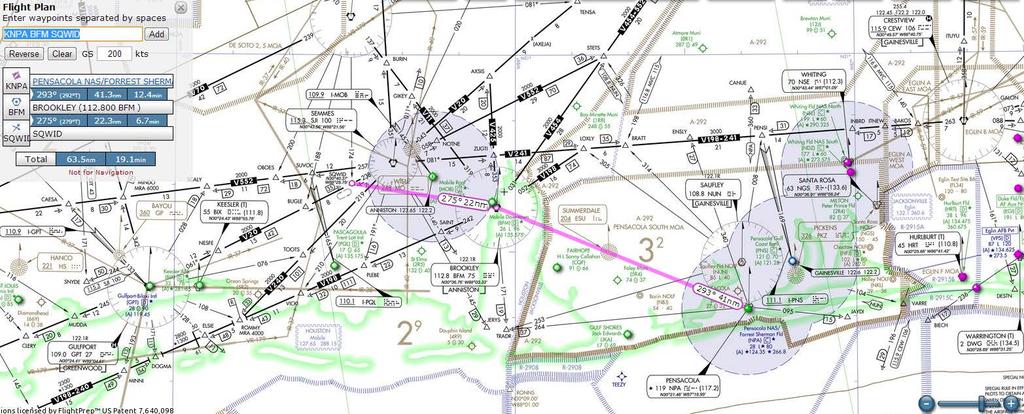
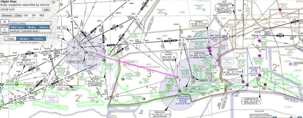
1 Q3201 WORKSHEET Planned Route: Takeoff: KNPA, RWY 25R Altitude: 6000 Route: KNPA BFM (VOR holding) Direct SQWID Approaches: KMOB VOR or TACAN-A (arcing approach) Alternate: KNPA via direct NUN Approaches: KNPA VOR RWY 19 (HILO) KPNS VOR RWY 08 (procedure turn). Prerequisites: -Q3103 -SY0302 FMS Trainer 2 Syllabus Notes: -Q3201 may be flown in the OFT or UTD Special Syllabus Requirements: -None Discuss Items a. Holding Speeds o Maximum (FAA) o Minimum/Recommended (NATOPS) Patterns/Entries o Standard o Non-Standard Corrections b. Enroute Descent NATOPS Recommended Procedure o Power/configuration o Airspeed o Descent rate o IDLE power/speed brake extended o Descent rate Max Range Descent profile
2 c. Missed approach Power Pitch Speed d. Teardrop approach NATOPS normal approach speeds o Configuration prior to FAF NATOPS minimum approach speeds o Prior to MDA/DH o After MDA/DH with field in sight With Flaps TO/LND FTI Procedure (recommended) e. Arcing approach FTI Procedure (recommended) f. HILO approach FTI Procedure (recommended) AIM Requirements g. Procedure Turn approach FTI Procedure (recommended) Situations where procedure is not required h. Any emergency procedure.
3 CNATRAINST B IUT T-6B NATOPS Instrument Q3200 Block IUT NATOPS GRADE SHEET DATE INSTRUCTOR MEDIA: OFT/UTD VT- BRIEF TIME: NAME: EVENT: CTS MANEUVER REF MIF Q3201 Q3202 Q GENERAL KNOWLEDGE / PROCEDURES 3+ X X X 2 EMERGENCY PROCEDURES 3+ X X X 3 HEADWORK / SITUATIONAL AWARENESS 3+ X X X 4 BASIC AIRWORK 3+ X X X 5 IN-FLIGHT CHECKS / FUEL MANAGEMENT 3+ X X X 6 IN-FLIGHT PLANNING / 3+ X X X AREA ORIENTATION 7 TASK MANAGEMENT 3+ X X X 8 COMMUNICATION 3+ X X X 9 MISSION PLANNING / BRIEFING / 3+ X X X DEBRIEFING 10 GROUND OPERATIONS 3+ X X X 11 TAKEOFF 3+ X X X 12 DEPARTURE 3+ X X X 44 HOLDING 3+ X 45 ENROUTE PROCEDURES 3+ X 46 ENROUTE DESCENT 3+ X 47 HIGH-ALTITUDE APPROACH 3+ X 48 TEARDROP APPROACH ARCING APPROACH 3+ X 50 HILO APPROACH 3+ X 51 PROCEDURE TURN APPROACH 3+ X 52 RVFAC APPROACH 3+ X 53 GPS APPROACH 3+ X 54 PAR APPROACH 3+ X 55 ASR APPROACH 3+ X 56 VOR FINAL 3+ X 57 ILS FINAL 3+ X 58 LOC FINAL 3+ X 59 GPS FINAL 3+ X 60 BACKUP FLIGHT INSTRUMENT APPROACH 3+ X 61 CIRCLING APPROACH 3+ X 62 MISSED APPROACH 3+ X 63 TRANSITION TO LANDING/LANDING 3+ X X Note: Q3201 may be flown in OFT or UTD; Q should be flown in OFT. Discuss Items: Q3201 Holding, enroute descent, missed approach, teardrop approach, arcing approach, HILO approach, and procedure turn approach. Q3202 RVFAC, ILS, localizer, high-altitude approach, and circling approaches. Q3203 PAR, ASR, no-gyro final, backup flight instrument approach, and GPS approaches B Rev 03/16/2017
4
5 15 R GCV Chan 104 MOBILE, ALABAMA VORTAC SJI Rwy Idg APP CRS TDZE Chan Apt Elev N/A N/A 219 AL-267 (FAA) VOR or TACAN-A MOBILE RGNL(MOB) T ASR MISSED APPROACH: Climb to 900, then climbing right turn to 2000 on heading 200 and SJI R-140 to SAINT INT/BFM 9.2 DME and hold. ATIS MOBILE APP CON MOBILE TOWER GND CON (CTAF) L CLNC DEL UNICOM MSA S J I25 NM 3100 R-284 (IF) TACCU SJI 7 IAF SEMMES SJI Chan 100 SE-4, 16 AUG 2018 to 13 SEP SJI Arc 1800 No PT (7) (IAF) SQWID SJI 7 R UBACE SJI R BROOKLEY BFM Chan 75 R-242 SE-4, 16 AUG 2018 to 13 SEP 2018 ELEV SAINT BFM 9.2 P A from FAF TWR NM 8502 X 150 H H P 4376 X H 36 x 283 x A Remain within 10 NM SJI VORTAC UBACE SJI 5.6 hdg 200 SJI R-140 SAINT MIRL Rwy HIRL Rwy FAF to MAP 5.6 NM Knots Min:Sec 5:36 3:44 2:48 2:14 1:52 MOBILE, ALABAMA Amdt 2A 29MAY14 CATEGORY A B C D C CIRCLING (500-1) 30 41'N-88 15'W 5.6 NM ( ) (600-2) MOBILE RGNL(MOB) VOR or TACAN-A
6
7 SE-3, 16 AUG 2018 to 13 SEP 2018 SE-3, 16 AUG 2018 to 13 SEP 2018
8 P 7004 X 150 PENSACOLA, FLORIDA NUN VOR APP CRS Rwy Idg 7000 TDZE 97 Apt Elev 121 AL-318 (FAA) VOR RWY 8 PENSACOLA INTL(PNS) T A 3 Helicopter visbility reduction below 4 SM NA. CAUTION: Intensive student training invof airport. MISSED APPROACH: Climb to 2000 then climbing left turn to 2600 direct NUN VOR and hold. ATIS PENSACOLA APP CON PENSACOLA TOWER (CTAF) L GND CON CLNC DEL UNICOM PENSI CEW (19.5) 442 SE-3, 16 AUG 2018 to 13 SEP 2018 ELEV 121 R-269 TDZE IAF SAUFLEY NUN NUN MSANU N25NM SE-3, 16 AUG 2018 to 13 SEP A NM from FAF 8 P 7000 X150 P Remain within 10 NM 269 NUN VOR NUN 146 TWR P 0.3% UP REIL Rwys 8, 26 and 35 TDZ/CL Rwy 17 L HIRL Rwys 8-26 and L FAF to MAP 7.3 NM Knots Min:Sec 7:18 4:52 3:39 2:55 2:26 PENSACOLA, FLORIDA Amdt 4B 24JUL14 CATEGORY A B S (700-1) CIRCLING (700-1) 30 28'N-87 11'W 7.3 NM C D (700-2) (700-2) 679 ( ) PENSACOLA INTL(PNS) VOR RWY 8
9 12/10/15 AIM FIG Holding Pattern Descriptive Terms ABEAM HOLDING SIDE FIX END RECIPROCAL FIX OUTBOUND INBOUND NONHOLDING SIDE OUTBOUND END HOLDING COURSE j. Holding pattern airspace protection is based on the following procedures. 1. Descriptive Terms. (a) Standard Pattern. Right turns (See FIG ) (b) Nonstandard Pattern. Left turns 2. Airspeeds. (a) All aircraft may hold at the following altitudes and maximum holding airspeeds: Altitude (MSL) TBL Airspeed (KIAS) MHA 6, ,001 14, ,001 and above 265 (b) The following are exceptions to the maximum holding airspeeds: (1) Holding patterns from 6,001 to 14,000 may be restricted to a maximum airspeed of 210 KIAS. This nonstandard pattern will be depicted by an icon. (2) Holding patterns may be restricted to a maximum speed. The speed restriction is depicted in parenthesis inside the holding pattern on the chart: e.g., (175). The aircraft should be at or below the maximum speed prior to initially crossing the holding fix to avoid exiting the protected airspace. Pilots unable to comply with the maximum airspeed restriction should notify ATC. (3) Holding patterns at USAF airfields only 310 KIAS maximum, unless otherwise depicted. (4) Holding patterns at Navy fields only 230 KIAS maximum, unless otherwise depicted. (5) When a climb in hold is specified by a published procedure (e.g., Climb in holding pattern to depart XYZ VORTAC at or above 10,000. or All aircraft climb in TRUCK holding pattern to cross TRUCK Int at or above 11,500 before proceeding on course. ), additional obstacle protection area has been provided to allow for greater airspeeds in the climb for those aircraft requiring them. The holding pattern template for a maximum airspeed of 310 KIAS has been used for the holding pattern if there are no airspeed restrictions on the holding pattern as specified in subparagraph j2(b)(2) of this paragraph. Where the holding pattern is restricted to a maximum airspeed of 175 KIAS, the 200 KIAS holding pattern template has been applied for published climb in hold procedures for altitudes 6,000 feet and below and the 230 KIAS holding pattern template has been applied for altitudes above 6,000 feet. The airspeed limitations in 14 CFR Section , Aircraft Speed, still apply. (c) The following phraseology may be used by an ATCS to advise a pilot of the maximum holding airspeed for a holding pattern airspace area. PHRASEOLOGY (AIRCRAFT IDENTIFICATION) (holding instructions, when needed) MAXIMUM HOLDING AIRSPEED IS (speed in knots). En Route Procedures
10 With canopy defog ON, expect an increase in ITT of up to 40 C for a given PCL setting. Cockpit noise will also increase. Performance will decrease with defog on. A DUCT TEMP indication is likely at climb or cruise power with canopy defog ON and cockpit temperature controller set to AUTO or MAN- UAL HOT. Refer to Environmental Systems Duct Overtemp procedure in Section III. 3. Vent control lever - As required 4. Pressurization system - Check If readings other than 3.6±0.2 psi are encountered at or above 18,069 feet PA, notify maintenance. OPERATIONS CHECK At initial level-off and periodically during the flight, perform the following checks: 1. Hydraulic pressure - Check 2. Electrical systems - Check 3. Fuel quantity/balance - Check 4. OBOGS - Check (BOTH) (Check flow indicator for normal operation) 5. Engine instruments - Check 6. Pressurization - Check PRE-STALLING, SPINNING, AND AEROBATIC CHECKS 1. Loose items - Stowed (BOTH) 2. Engine instruments - Check (Verify caution and warning messages are extinguished.) 3. Fuel balance - Check less than 50 pounds DESCENT The descent checklist is intended to be executed prior to entering the terminal environment after aerobatics have been performed or after transiting greater than 100nm. The recommended enroute descent procedure is power and configuration as required ( KIAS) and descent rate of 4000 fpm. Descent rates will increase significantly ( ,000 fpm) with idle power and speed brake extended. For maximum range descent profiles, refer to Appendix A. AIR FORCE TO 1T-6B-1 NAVY NAVAIR A1-T6BAA-NFM PFD - Check (BOTH) 2. Altimeters - Set (BOTH) 3. MASTER ARM switch - As required 4. DEFOG switch - As required 5. Vent control lever - As required HOLDING The recommended holding speed is KIAS in clean configuration but no slower than maximum endurance speed of 125 KIAS. When fuel endurance is a factor, refer to the Maximum Endurance data in Appendix A. INSTRUMENT APPROACHES Refer to Figure 2-6 for a typical instrument approach. The aircraft is considered Category B for determination of instrument approach minimums. PENETRATION DESCENT For a penetration descent, retard the PCL as required to meet a target descent rate ( fpm). Attain KIAS and use speed brake as required. LOW ALTITUDE APPROACH Normally fly instrument approaches at KIAS. Prior to the final approach fix, ensure the landing gear is down and flaps are set to TO, and slow to a minimum of 110 KIAS. With the field in sight and departing the MDA, DA, or DH, slow to 105 KIAS minimum, or the pilot may select landing flaps and slow to 100 KIAS minimum. Fly GPS approaches using the above airspeeds and configurations. The GPS always displays distance to the active waypoint. During GPS approaches, this distance may not be the same as the published DME distance on the instrument approach procedure. RADAR APPROACH Figure 2-7 shows a typical radar approach. Maintain KIAS in clean configuration on radar downwind. Slow to KIAS on base leg. Prior to glideslope intercept, ensure that landing gear are down and set flaps as required. Fly final approach at KIAS. 2-23
11 With canopy defog ON, expect an increase in ITT of up to 40 C for a given PCL setting. Cockpit noise will also increase. Performance will decrease with defog on. A DUCT TEMP indication is likely at climb or cruise power with canopy defog ON and cockpit temperature controller set to AUTO or MAN- UAL HOT. Refer to Environmental Systems Duct Overtemp procedure in Section III. 3. Vent control lever - As required 4. Pressurization system - Check If readings other than 3.6±0.2 psi are encountered at or above 18,069 feet PA, notify maintenance. OPERATIONS CHECK At initial level-off and periodically during the flight, perform the following checks: 1. Hydraulic pressure - Check 2. Electrical systems - Check 3. Fuel quantity/balance - Check 4. OBOGS - Check (BOTH) (Check flow indicator for normal operation) 5. Engine instruments - Check 6. Pressurization - Check PRE-STALLING, SPINNING, AND AEROBATIC CHECKS 1. Loose items - Stowed (BOTH) 2. Engine instruments - Check (Verify caution and warning messages are extinguished.) 3. Fuel balance - Check less than 50 pounds DESCENT The descent checklist is intended to be executed prior to entering the terminal environment after aerobatics have been performed or after transiting greater than 100nm. The recommended enroute descent procedure is power and configuration as required ( KIAS) and descent rate of 4000 fpm. Descent rates will increase significantly ( ,000 fpm) with idle power and speed brake extended. For maximum range descent profiles, refer to Appendix A. AIR FORCE TO 1T-6B-1 NAVY NAVAIR A1-T6BAA-NFM PFD - Check (BOTH) 2. Altimeters - Set (BOTH) 3. MASTER ARM switch - As required 4. DEFOG switch - As required 5. Vent control lever - As required HOLDING The recommended holding speed is KIAS in clean configuration but no slower than maximum endurance speed of 125 KIAS. When fuel endurance is a factor, refer to the Maximum Endurance data in Appendix A. INSTRUMENT APPROACHES Refer to Figure 2-6 for a typical instrument approach. The aircraft is considered Category B for determination of instrument approach minimums. PENETRATION DESCENT For a penetration descent, retard the PCL as required to meet a target descent rate ( fpm). Attain KIAS and use speed brake as required. LOW ALTITUDE APPROACH Normally fly instrument approaches at KIAS. Prior to the final approach fix, ensure the landing gear is down and flaps are set to TO, and slow to a minimum of 110 KIAS. With the field in sight and departing the MDA, DA, or DH, slow to 105 KIAS minimum, or the pilot may select landing flaps and slow to 100 KIAS minimum. Fly GPS approaches using the above airspeeds and configurations. The GPS always displays distance to the active waypoint. During GPS approaches, this distance may not be the same as the published DME distance on the instrument approach procedure. RADAR APPROACH Figure 2-7 shows a typical radar approach. Maintain KIAS in clean configuration on radar downwind. Slow to KIAS on base leg. Prior to glideslope intercept, ensure that landing gear are down and set flaps as required. Fly final approach at KIAS. 2-23
12 AIR FORCE TO 1T-6B-1 NAVY NAVAIR A1-T6BAA-NFM ENTRY 4 INBOUND APPROACH FIX GEAR DOWN, PERFORM BEFORE LANDING CHECK LIST FINAL 2 OUTBOUND PROCEDURE TURN 1 2 MISSED APPROACH POWER - MAXIMUM RATE OF CLIMB - ESTABLISHED GEAR - UP 6 FLAPS - UP 5 APPROACH FIX 4 3 RECOMMENDED APPROACH AIRSPEED - KIAS PROCEDURE MISSED ENTRY 1 OUTBOUND 2 3 INBOUND 4 FINAL 5 6 TURN APPROACH AS DESIRED THESE PROCEDURES ARE NOT INTENDED TO LIMIT THE PILOT'S PREROGATIVE TO ALTER AIRSPEEDS AND CONFIGURATIONS TO MEET EXISTING CONDITIONS. WHEN ON FINAL, THE PILOT HAS THE OPTION OF SELECTING LDG FLAPS AND SLOWING TO FINAL APPROACH SPEED. PT02D AA.AI Figure 2-6. Typical Instrument (Non Radar) Approach 2-24
13 With canopy defog ON, expect an increase in ITT of up to 40 C for a given PCL setting. Cockpit noise will also increase. Performance will decrease with defog on. A DUCT TEMP indication is likely at climb or cruise power with canopy defog ON and cockpit temperature controller set to AUTO or MAN- UAL HOT. Refer to Environmental Systems Duct Overtemp procedure in Section III. 3. Vent control lever - As required 4. Pressurization system - Check If readings other than 3.6±0.2 psi are encountered at or above 18,069 feet PA, notify maintenance. OPERATIONS CHECK At initial level-off and periodically during the flight, perform the following checks: 1. Hydraulic pressure - Check 2. Electrical systems - Check 3. Fuel quantity/balance - Check 4. OBOGS - Check (BOTH) (Check flow indicator for normal operation) 5. Engine instruments - Check 6. Pressurization - Check PRE-STALLING, SPINNING, AND AEROBATIC CHECKS 1. Loose items - Stowed (BOTH) 2. Engine instruments - Check (Verify caution and warning messages are extinguished.) 3. Fuel balance - Check less than 50 pounds DESCENT The descent checklist is intended to be executed prior to entering the terminal environment after aerobatics have been performed or after transiting greater than 100nm. The recommended enroute descent procedure is power and configuration as required ( KIAS) and descent rate of 4000 fpm. Descent rates will increase significantly ( ,000 fpm) with idle power and speed brake extended. For maximum range descent profiles, refer to Appendix A. AIR FORCE TO 1T-6B-1 NAVY NAVAIR A1-T6BAA-NFM PFD - Check (BOTH) 2. Altimeters - Set (BOTH) 3. MASTER ARM switch - As required 4. DEFOG switch - As required 5. Vent control lever - As required HOLDING The recommended holding speed is KIAS in clean configuration but no slower than maximum endurance speed of 125 KIAS. When fuel endurance is a factor, refer to the Maximum Endurance data in Appendix A. INSTRUMENT APPROACHES Refer to Figure 2-6 for a typical instrument approach. The aircraft is considered Category B for determination of instrument approach minimums. PENETRATION DESCENT For a penetration descent, retard the PCL as required to meet a target descent rate ( fpm). Attain KIAS and use speed brake as required. LOW ALTITUDE APPROACH Normally fly instrument approaches at KIAS. Prior to the final approach fix, ensure the landing gear is down and flaps are set to TO, and slow to a minimum of 110 KIAS. With the field in sight and departing the MDA, DA, or DH, slow to 105 KIAS minimum, or the pilot may select landing flaps and slow to 100 KIAS minimum. Fly GPS approaches using the above airspeeds and configurations. The GPS always displays distance to the active waypoint. During GPS approaches, this distance may not be the same as the published DME distance on the instrument approach procedure. RADAR APPROACH Figure 2-7 shows a typical radar approach. Maintain KIAS in clean configuration on radar downwind. Slow to KIAS on base leg. Prior to glideslope intercept, ensure that landing gear are down and set flaps as required. Fly final approach at KIAS. 2-23
14 AIR FORCE TO 1T-6B-1 NAVY NAVAIR A1-T6BAA-NFM ENTRY 4 INBOUND APPROACH FIX GEAR DOWN, PERFORM BEFORE LANDING CHECK LIST FINAL 2 OUTBOUND PROCEDURE TURN 1 2 MISSED APPROACH POWER - MAXIMUM RATE OF CLIMB - ESTABLISHED GEAR - UP 6 FLAPS - UP 5 APPROACH FIX 4 3 RECOMMENDED APPROACH AIRSPEED - KIAS PROCEDURE MISSED ENTRY 1 OUTBOUND 2 3 INBOUND 4 FINAL 5 6 TURN APPROACH AS DESIRED THESE PROCEDURES ARE NOT INTENDED TO LIMIT THE PILOT'S PREROGATIVE TO ALTER AIRSPEEDS AND CONFIGURATIONS TO MEET EXISTING CONDITIONS. WHEN ON FINAL, THE PILOT HAS THE OPTION OF SELECTING LDG FLAPS AND SLOWING TO FINAL APPROACH SPEED. PT02D AA.AI Figure 2-6. Typical Instrument (Non Radar) Approach 2-23
15 With canopy defog ON, expect an increase in ITT of up to 40 C for a given PCL setting. Cockpit noise will also increase. Performance will decrease with defog on. A DUCT TEMP indication is likely at climb or cruise power with canopy defog ON and cockpit temperature controller set to AUTO or MAN- UAL HOT. Refer to Environmental Systems Duct Overtemp procedure in Section III. 3. Vent control lever - As required 4. Pressurization system - Check If readings other than 3.6±0.2 psi are encountered at or above 18,069 feet PA, notify maintenance. OPERATIONS CHECK At initial level-off and periodically during the flight, perform the following checks: 1. Hydraulic pressure - Check 2. Electrical systems - Check 3. Fuel quantity/balance - Check 4. OBOGS - Check (BOTH) (Check flow indicator for normal operation) 5. Engine instruments - Check 6. Pressurization - Check PRE-STALLING, SPINNING, AND AEROBATIC CHECKS 1. Loose items - Stowed (BOTH) 2. Engine instruments - Check (Verify caution and warning messages are extinguished.) 3. Fuel balance - Check less than 50 pounds DESCENT The descent checklist is intended to be executed prior to entering the terminal environment after aerobatics have been performed or after transiting greater than 100nm. The recommended enroute descent procedure is power and configuration as required ( KIAS) and descent rate of 4000 fpm. Descent rates will increase significantly ( ,000 fpm) with idle power and speed brake extended. For maximum range descent profiles, refer to Appendix A. AIR FORCE TO 1T-6B-1 NAVY NAVAIR A1-T6BAA-NFM PFD - Check (BOTH) 2. Altimeters - Set (BOTH) 3. MASTER ARM switch - As required 4. DEFOG switch - As required 5. Vent control lever - As required HOLDING The recommended holding speed is KIAS in clean configuration but no slower than maximum endurance speed of 125 KIAS. When fuel endurance is a factor, refer to the Maximum Endurance data in Appendix A. INSTRUMENT APPROACHES Refer to Figure 2-6 for a typical instrument approach. The aircraft is considered Category B for determination of instrument approach minimums. PENETRATION DESCENT For a penetration descent, retard the PCL as required to meet a target descent rate ( fpm). Attain KIAS and use speed brake as required. LOW ALTITUDE APPROACH Normally fly instrument approaches at KIAS. Prior to the final approach fix, ensure the landing gear is down and flaps are set to TO, and slow to a minimum of 110 KIAS. With the field in sight and departing the MDA, DA, or DH, slow to 105 KIAS minimum, or the pilot may select landing flaps and slow to 100 KIAS minimum. Fly GPS approaches using the above airspeeds and configurations. The GPS always displays distance to the active waypoint. During GPS approaches, this distance may not be the same as the published DME distance on the instrument approach procedure. RADAR APPROACH Figure 2-7 shows a typical radar approach. Maintain KIAS in clean configuration on radar downwind. Slow to KIAS on base leg. Prior to glideslope intercept, ensure that landing gear are down and set flaps as required. Fly final approach at KIAS. 2-23
16 AIR FORCE TO 1T-6B-1 NAVY NAVAIR A1-T6BAA-NFM-100 FINAL KIAS GEAR - DOWN FLAPS - AS REQUIRED DOWNWIND KIAS CLEAN THESE PROCEDURES ARE NOT INTENDED TO LIMIT THE PILOT'S PREROGATIVE TO ALTER AIRSPEEDS AND CONFIGURATIONS TO MEET EXISTING CONDITIONS. BASE KIAS GEAR - AS REQUIRED FLAPS - AS REQUIRED PT02D AA.AI Figure 2-7. Typical Radar Approach CIRCLING APPROACH Minimum recommended speed prior to final approach is 115 KIAS with gear down and flaps set to TO. MISSED APPROACH Smoothly advance PCL to MAX power and retract the speed brake (if extended). Set attitude to nose high and execute air traffic control (ATC) missed approach procedure. Maintain the landing approach speed until clear of obstacles. Reduce power as required to preclude excessive nose high attitude in actual instrument conditions. Refer to the After Takeoff checklist. Selection of MAX power automatically retracts the speed brake. BEFORE LANDING Refer to Appendix A for recommended landing data. The flaps may be set to TO prior to lowering gear. Prior to landing, set pressurization switch to DUMP if landing field elevation is above 7500 feet MSL. 1. DEFOG switch - OFF 2. Engine instruments - Check 3. Gear - DOWN (BOTH) (Check three green annunciators illuminated) 4. Brakes - Check, as required (Verify positive pressure by actuating toe brakes) 5. Flaps - As required (BOTH) 6. Speed brake - Retracted Setting flaps to TO or LDG automatically retracts the speed brake. If conditions require, the pilot may select defog during climbout from missed approach, go around/waveoff, or touch and go. GO AROUND/WAVEOFF The decision to go around/waveoff should be made as early as possible. Go around/waveoff procedures are similar to missed approach. Refer to the After Takeoff checklist. 2-25
17 AIR FORCE TO 1T-6B-1 NAVY NAVAIR A1-T6BAA-NFM-100 FINAL KIAS GEAR - DOWN FLAPS - AS REQUIRED DOWNWIND KIAS CLEAN THESE PROCEDURES ARE NOT INTENDED TO LIMIT THE PILOT'S PREROGATIVE TO ALTER AIRSPEEDS AND CONFIGURATIONS TO MEET EXISTING CONDITIONS. BASE KIAS GEAR - AS REQUIRED FLAPS - AS REQUIRED PT02D AA.AI Figure 2-7. Typical Radar Approach CIRCLING APPROACH Minimum recommended speed prior to final approach is 115 KIAS with gear down and flaps set to TO. MISSED APPROACH Smoothly advance PCL to MAX power and retract the speed brake (if extended). Set attitude to nose high and execute air traffic control (ATC) missed approach procedure. Maintain the landing approach speed until clear of obstacles. Reduce power as required to preclude excessive nose high attitude in actual instrument conditions. Refer to the After Takeoff checklist. Selection of MAX power automatically retracts the speed brake. BEFORE LANDING Refer to Appendix A for recommended landing data. The flaps may be set to TO prior to lowering gear. Prior to landing, set pressurization switch to DUMP if landing field elevation is above 7500 feet MSL. 1. DEFOG switch - OFF 2. Engine instruments - Check 3. Gear - DOWN (BOTH) (Check three green annunciators illuminated) 4. Brakes - Check, as required (Verify positive pressure by actuating toe brakes) 5. Flaps - As required (BOTH) 6. Speed brake - Retracted Setting flaps to TO or LDG automatically retracts the speed brake. If conditions require, the pilot may select defog during climbout from missed approach, go around/waveoff, or touch and go. GO AROUND/WAVEOFF The decision to go around/waveoff should be made as early as possible. Go around/waveoff procedures are similar to missed approach. Refer to the After Takeoff checklist. 2-25
18 AIR FORCE TO 1T-6B-1 NAVY (NAVAIR) A1-T6BAA-NFM-100 ASSOCIATED CONDITIONS: POWER AS REQUIRED TO MAINTAIN 15OO FPM RATE OF DESCENT 18O KIAS DESCENT SPEED LANDING GEAR UP FLAPS UP SPEEDBRAKE IN MAXIMUM RANGE DESCENT TIME, FUEL AND DISTANCE AIRPLANE : T-6B ENGINE : PT6A-68 DATE : MAR 2OO8 DATA BASIS : FLIGHT TEST PRESSURE ALTITUDE ~ 1000 FEET PHAADE002A TIME TO DESCEND ~ MINUTES FUEL TO DESCEND ~ POUNDS DISTANCE TO DESCENT ~ NAUTICAL MILES Figure A7-2. Maximum Range Descent A7-5
19 CHAPTER EIGHT PRIMARY INSTRUMENT NAVIGATION T-6B 814. PROCEDURE TURN APPROACH General Reverse the aircraft heading within assigned airspace in order to align it with the final approach course. Description The Procedure Turn Approach is an instrument maneuver used to reverse direction and establish the aircraft inbound on the intermediate or final approach course while insuring the Remain Within distance is observed. Procedure Turns are depicted by a barb symbol on the approach plate. The Barb indicates which side of the outbound course to complete the turn (Figure 8-8). Headings are provided to reverse course using a 45/180 degrees type maneuver. However, the point at which the turn may be commenced and the type and rate of turn, are left to the discretion of the pilot, as long as the Procedure Turn is executed on the proper side of the outbound course and the Remain Within distance (normally 10 NM) is not exceeded. Options for this type of maneuver include the 45/180 degrees course reversal, the racetrack pattern, or the 80/260 degree course reversal. During Primary training, only the 45/180 degrees course reversal will be practiced. Do NOT execute a Procedure Turn when: 1. ATC clears you for a Straight-in approach. 2. Flying the approach via NoPT routing. 3. Established in a holding pattern aligned with the procedure turn course and subsequently cleared for the approach. 4. ATC Radar vectors you to final. 5. Cleared for a Timed approach. SNERT is a useful mnemonic to aid in recall of these restrictions. Procedure The following procedures assume clearance for the DAYTONA BEACH INTERNATIONAL VOR RWY 16 approach (Figure 8-8) has been received and you are proceeding to the IAF. 1. Approximately 5 NM prior to the IAF, slow to 150 KIAS. At the IAF, indicated by station passage, execute the 6 Ts (Over-the-Station Intercept): a. TIME - Not required TERMINAL PROCEDURES
20 PRIMARY INSTRUMENT NAVIGATION T-6B CHAPTER EIGHT b. TURN - in the shortest direction to parallel the outbound course (336º). If the outbound course is more than 90 from the course used inbound to the IAF, turn to an intercept heading not to exceed 45. c. TIME - Start timing for one (1) minute outbound when wings level or abeam the station, whichever occurs last. Comply with the remain within distance if stated on the approach plate. d. TRANSITION - If a descent is necessary at the IAF, set approximately 15% torque, lower the nose, and descend at 150 KIAS. Comply with any additional altitude restrictions imposed by ATC. e. TWIST/ Intercept i. Set CDI to the outbound course (336º). ii. Use Over-the-Station Intercept procedures to establish the aircraft on course outbound. The objective is to be established on the outbound radial by the end of one minute. f. TALK - Give an appropriate voice report if required. 2. Level-off at Procedure Turn altitude (1600 ). a. Approximately 100 prior to the Procedure Turn altitude, add power smoothly towards 33% torque as you raise the nose to level flight attitude and re-trim. b. Maintain Procedure Turn altitude until you are established on the inbound course. The aircraft is not considered established on course until the head of the bearing pointer is within five radials of the inbound course. With the CDI set correctly, the course deviation bar will be between the one dot and centered position. 3. At the end of outbound timing, execute the 45/180 degrees course reversal by turning 45 to the heading depicted on the barb symbol (291º). Start the clock as you roll wings level and maintain this heading for one (1) minute. Twist in the inbound course (156º) in the CDI. TERMINAL PROCEDURES 8-15
21 CHAPTER EIGHT PRIMARY INSTRUMENT NAVIGATION T-6B 4. At the end of one (1) minute timing, execute a 180º turn in a direction opposite the first turn (i.e., turn away from the station). Approaching the barb heading (111 ), note the head of the bearing pointer. a. If the head of the bearing pointer is not within 5 of the inbound course, stop the turn on the heading depicted on the barb (111 ). b. If the head of the needle is within 5 of the inbound course, continue the turn and roll out with a double-the-angle intercept. If you overshoot the inbound course, turn to establish an appropriate intercept. 5. As you intercept the inbound course, turn and track inbound. 6. Once established on the inbound course, and within 5 NM of the FAF (when DME is available), configure to BAC. Maintain altitude until reaching 120 KIAS then commence any descent required (Slow Down, Then Go Down). In this case maintain 1600 until the FAF. 7. Comply with the remainder of the Low Altitude Instrument Approach Procedures TERMINAL PROCEDURES
 TERMINAL PROCEDURES")
22 PRIMARY INSTRUMENT NAVIGATION T-6B CHAPTER EIGHT Figure 8-8 VOR RWY 16 (KDAB) TERMINAL PROCEDURES 8-17
23 CHAPTER EIGHT PRIMARY INSTRUMENT NAVIGATION T-6B 815. TEARDROP APPROACH General Reverse the aircraft heading in order to align it with the final approach course. Description A Teardrop approach makes use of an outbound to inbound radial intercept maneuver to reverse course and establish the aircraft inbound on the intermediate or final approach course while insuring the Remain Within distance is observed. A Non-Depicted Teardrop approach is an authorized variant to the Procedure Turn, and is flown by intercepting an outbound radial offset 20 to the protected barb side of the Procedure Turn Final Approach Course. Procedure The following procedures assume clearance for the ROBINS AFB VOR RWY 15 approach (Figure 8-9) has been received and you are proceeding to the IAF. 1. Approximately 5 NM prior to the IAF, slow to 150 KIAS. At the IAF, indicated by station passage, execute the 6 Ts (Over-the-Station Intercept): a. TIME - Not required. b. TURN - Turn in the shortest direction to parallel the outbound course (295º). If the outbound course is more than 90 from the course used inbound to the IAF, turn to an intercept heading not to exceed 45. c. TIME - Start timing for two (2) minutes outbound when wings level or abeam the station, whichever occurs last. In strong winds or at indicated speeds greater than 150 KIAS, you may have to adjust outbound timing to comply with any Remain Within distance associated with the approach. Normally, (2) two minutes timing outbound will be sufficient. d. TRANSITION - If a descent is necessary at the IAF, set approximately 15% torque, and descend at 150 KIAS. Comply with any additional altitude restrictions imposed by ATC TERMINAL PROCEDURES
24 PRIMARY INSTRUMENT NAVIGATION T-6B CHAPTER EIGHT e. TWIST /Intercept i. Set the outbound course (295º) into the CDI. ii. Use Over-the-Station Intercept Procedures to establish the aircraft on course outbound. The objective is to be established on the outbound radial by the end of one minute. f. TALK - Give an appropriate voice report if required. 2. Level-off at Procedure Turn altitude (2300 ). a. Approximately 100 prior to the Procedure Turn altitude, add power and raise the nose to maintain 150 KIAS in level flight. Continue to re-trim. b. Maintain Procedure Turn altitude until you are established on the inbound course. The aircraft is not considered established on course until the head of the bearing pointer is within five radials of the inbound course. With the CDI set correctly, the course deviation bar will be between the one dot and centered position. 3. After 1 ½ minutes of outbound timing, twist inbound course into the CDI (134º). 4. At two (2) minutes of outbound timing, execute a turn in the direction depicted (in this case, turn right). During the turn inbound note the position of the bearing pointer: a. If the head of the bearing pointer is not within 5º of the inbound course, stop the turn with a 45º intercept. b. If the head of the bearing pointer is within 5º of the inbound course, you should roll out with a double the angle intercept. If you overshoot the inbound course, turn to establish an appropriate intercept. 5. Once established on the inbound course, and within 5 NM of the FAF (when DME is available), configure to BAC. Maintain altitude until reaching 120 KIAS then commence any descent required (in this case descend to 1500 MSL, Slow Down, Then Go Down). 6. Comply with the remainder of the Low Altitude Instrument Approach Procedures. To facilitate training, if local VOR approaches do not have a Teardrop procedure available, a procedure turn approach may be TERMINAL PROCEDURES 8-19
25 CHAPTER EIGHT PRIMARY INSTRUMENT NAVIGATION T-6B used to substitute by intercepting an outbound radial offset 20º to the barb side of a depicted procedure turn Final approach course and continue with FTI procedures for a Teardrop procedure turn. Figure 8-9 VOR RWY 15 (KWRB) 8-20 TERMINAL PROCEDURES
26 PRIMARY INSTRUMENT NAVIGATION T-6B CHAPTER EIGHT 816. ARCING APPROACH General Establish the aircraft inbound on the final approach course. Description An Arcing approach makes use of an arcing maneuver to position the aircraft inbound on an intermediate or final approach course. Arcing approaches are normally identified by VOR/DME or TACAN in the approach plate margin, indicating DME is required. Procedure The following procedures assume clearance for the VOR/DME Z or TACAN Z RWY 13R (KNGP) approach (Figure 8-10) has been received and you are proceeding direct to the IAF. 1. Approximately 5 NM prior to the IAF and commencing the approach, slow to 150 KIAS. At the IAF, execute the 6 T s: a. TIME - Not required. b. TURN - To place the VOR bearing pointer at the 90º benchmark. Use Radial/Arc and Arc/Radial intercepts to make the turn onto and off of the arc. c. TIME - Not required. d. TRANSITION - Comply with altitude restrictions as required (no lower than 1600 inbound from RYNOL to FAF). e. TWIST - Ensure the inbound course (143º) is set in the CDI. f. TALK - Give an appropriate voice report if required. 2. Anticipate interception of the final approach course (reference the bearing pointer and CDI). Use an appropriate lead radial for the 90 degree turn. TERMINAL PROCEDURES 8-21
27 CHAPTER EIGHT PRIMARY INSTRUMENT NAVIGATION T-6B On some approach charts, a published lead radial (designated LR-xxx ) is provided as an advisory point for turning onto the inbound course. These designated lead radials are based on an aircraft groundspeed of 200 knots and using a ½ SRT. For normal approach speeds of 150 KIAS compute the lead radial based on an SRT. 3. When within 5 NM of the FAF, make a level or descending transition to BAC, as required. 4. Once established inbound, comply with the remainder of the Low Altitude Instrument Approach Procedures. Common Errors 1. Overshooting the arc or final approach course due to insufficient lead or slow scan of instruments. 2. Failure to descend to minimum altitudes for the various approach segments TERMINAL PROCEDURES
 TERMINAL PROCEDURES 8-23")
28 PRIMARY INSTRUMENT NAVIGATION T-6B CHAPTER EIGHT Figure 8-10 VOR/DME Z or TACAN Z RWY 13R (KNGP) TERMINAL PROCEDURES 8-23
29 CHAPTER EIGHT PRIMARY INSTRUMENT NAVIGATION T-6B 817. HOLDING PATTERN APPROACH (HILO) General The Holding Pattern Approach/Holding In Lieu Of (HILO) is a type of a procedure turn. Description The HILO approach uses a published holding pattern to reverse course and establish the aircraft inbound on the intermediate or final approach course. HILO approaches are printed using a normal holding pattern track with a heavy line indicating In lieu of Procedure Turn. The entry maneuvering in the pattern utilizes normal holding procedures. Only one turn in the Holding Pattern is authorized. If more turns are necessary to lose excessive altitude or to become better established on course, ATC clearance must be obtained. In Figure 8-11 below, Case I allows for a descent to the initial published altitude (1600 ) during the entry orbit but no lower until crossing the FAF. Case II depicts a minimum holding altitude where a descent below the initial altitude (to 1300 ) may be conducted once established inbound. Figure 8-11 Holding Fix Descent Unlike the Teardrop and Procedure Turn approaches, the Holding Pattern approach will always have a FAF depicted on the approach. Procedure The following procedures assume clearance for the MARIANNA MUNI VOR or GPS A approach (Figure 8-12) has been received and you are proceeding to the IAF. 1. Approximately 5 NM prior to the IAF, slow to 150 KIAS. At the IAF, indicated by station passage, execute the 6 Ts. a. TIME - Not required 8-24 TERMINAL PROCEDURES
30 PRIMARY INSTRUMENT NAVIGATION T-6B CHAPTER EIGHT b. TURN - Use normal Holding Pattern entry procedures to determine the entry heading and turn direction. Turn in the shortest direction to your entry heading. c. TIME - Start timing as required (one minute in this case) when wings level or abeam the station, whichever occurs last. d. TRANSITION - If a descent is necessary at the IAF (2000 ), set approximately 15% torque, lower the nose, and descend at 150 KIAS. Comply with any additional altitude restrictions imposed by ATC. e. TWIST Enter in the depicted inbound course (316º) into the CDI. f. TALK Give the appropriate voice report if required. 2. Determine direction for the turn to intercept the inbound course (316º). TAIL RADIAL TURN! 3. At the completion of the outbound leg, turn inbound. Roll out of the turn with an appropriate intercept to establish the aircraft on the inbound course prior to crossing the holding fix (a double the angle intercept will normally suffice when over a VOR). 4. Once established inbound, and when within 5 NM of FAF (when DME is available), make a level or descending transition to BAC as required (descending transition down to 1700 in this case Slow Down, Then Go Down). 5. Comply with the remainder of the Low Altitude Instrument Approach Procedures. TERMINAL PROCEDURES 8-25
31 CHAPTER EIGHT PRIMARY INSTRUMENT NAVIGATION T-6B Figure 8-12 VOR or GPS-A (KMAI) 8-26 TERMINAL PROCEDURES
32 R AIM CHG 2 12/10/15 3/15/07 5/26/16 pilots operating properly equipped and airworthy aircraft in accordance with operating rules and procedures acceptable to the FAA. Special IAPs are also developed using TERPS but are not given public notice in the FR. The FAA authorizes only certain individual pilots and/or pilots in individual organizations to use special IAPs, and may require additional crew training and/or aircraft equipment or performance, and may also require the use of landing aids, communications, or weather services not available for public use. Additionally, IAPs that service private use airports or heliports are generally special IAPs. FDC NOTAMs for Specials, FDC T-NOTAMs, may also be used to promulgate safety-of-flight information relating to Specials provided the location has a valid landing area identifier and is serviced by the United States NOTAM system. Pilots may access NOTAMs online or through an FAA Flight Service Station (FSS). FSS specialists will not automatically provide NOTAM information to pilots for special IAPs during telephone pre flight briefings. Pilots who are authorized by the FAA to use special IAPs must specifically request FDC NOTAM information for the particular special IAP they plan to use Procedure Turn and Hold in lieu of Procedure Turn a. A procedure turn is the maneuver prescribed when it is necessary to reverse direction to establish the aircraft inbound on an intermediate or final approach course. The procedure turn or hold in lieu of PT is a required maneuver when it is depicted on the approach chart, unless cleared by ATC for a straight in approach. Additionally, the procedure turn or hold in lieu of PT is not permitted when the symbol No PT is depicted on the initial segment being used, when a RADAR VECTOR to the final approach course is provided, or when conducting a timed approach from a holding fix. The altitude prescribed for the procedure turn is a minimum altitude until the aircraft is established on the inbound course. The maneuver must be completed within the distance specified in the profile view. For a hold in lieu of PT, the holding pattern direction must be flown as depicted and the specified leg length/timing must not be exceeded. The pilot may elect to use the procedure turn or hold in lieu of PT when it is not required by the procedure, but must first receive an amended clearance from ATC. If the pilot is uncertain whether the ATC clearance intends for a procedure turn to be conducted or to allow for a straight in approach, the pilot must immediately request clarification from ATC (14 CFR Section ). 1. On U.S. Government charts, a barbed arrow indicates the maneuvering side of the outbound course on which the procedure turn is made. Headings are provided for course reversal using the 45 degree type procedure turn. However, the point at which the turn may be commenced and the type and rate of turn is left to the discretion of the pilot (limited by the charted remain within xx NM distance). Some of the options are the 45 degree procedure turn, the racetrack pattern, the teardrop procedure turn, or the 80 degree 260 degree course reversal. Racetrack entries should be conducted on the maneuvering side where the majority of protected airspace resides. If an entry places the pilot on the non maneuvering side of the PT, correction to intercept the outbound course ensures remaining within protected airspace. Some procedure turns are specified by procedural track. These turns must be flown exactly as depicted. 2. Descent to the procedure turn (PT) completion altitude from the PT fix altitude (when one has been published or assigned by ATC) must not begin until crossing over the PT fix or abeam and proceeding outbound. Some procedures contain a note in the chart profile view that says Maintain (altitude) or above until established outbound for procedure turn (See FIG ). Newer procedures will simply depict an at or above altitude at the PT fix without a chart note (See FIG ). Both are there to ensure required obstacle clearance is provided in the procedure turn entry zone (See FIG ). Absence of a chart note or specified minimum altitude adjacent to the PT fix is an indication that descent to the procedure turn altitude can commence immediately upon crossing over the PT fix, regardless of the direction of flight. This is because the minimum altitudes in the PT entry zone and the PT maneuvering zone are the same Arrival Procedures
33 7/26/12 AIM procedure turn (See FIG ). Newer procedures will simply depict an at or above altitude at the PT fix without a chart note (See FIG ). Both are there to ensure required obstacle clearance is provided in the procedure turn entry zone (See FIG ). Absence of a chart note FIG or specified minimum altitude adjacent to the PT fix is an indication that descent to the procedure turn altitude can commence immediately upon crossing over the PT fix, regardless of the direction of flight. This is because the minimum altitudes in the PT entry zone and the PT maneuvering zone are the same. FIG Arrival Procedures
 should be observed from first overheading the course reversal IAF through the procedure turn")
34 AIM 7/26/12 FIG When the approach procedure involves a procedure turn, a maximum speed of not greater than 200 knots (IAS) should be observed from first overheading the course reversal IAF through the procedure turn maneuver to ensure containment within the obstruction clearance area. Pilots should begin the outbound turn immediately after passing the procedure turn fix. The procedure turn maneuver must be executed within the distance specified in the profile view. The normal procedure turn distance is 10 miles. This may be reduced to a minimum of 5 miles where only Category A or helicopter aircraft are to be operated or increased to as much as 15 miles to accommodate high performance aircraft A teardrop procedure or penetration turn may be specified in some procedures for a required course reversal. The teardrop procedure consists of departure from an initial approach fix on an outbound course followed by a turn toward and intercepting the inbound course at or prior to the intermediate fix or point. Its purpose is to permit an aircraft to reverse direction and lose considerable altitude within reasonably limited airspace. Where no fix is available to mark the beginning of the intermediate segment, it must be assumed to commence at a point 10 miles prior to the final approach fix. When the facility is located on the airport, an aircraft is considered to be on final approach upon completion of the penetration turn. However, the final approach segment begins on the final approach course 10 miles from the facility. Arrival Procedures
35 7/26/12 AIM 5. A holding pattern in lieu of procedure turn may be specified for course reversal in some procedures. In such cases, the holding pattern is established over an intermediate fix or a final approach fix. The holding pattern distance or time specified in the profile view must be observed. For a hold in lieu of PT, the holding pattern direction must be flown as depicted and the specified leg length/timing must not be exceeded. Maximum holding airspeed limitations as set forth for all holding patterns apply. The holding pattern maneuver is completed when the aircraft is established on the inbound course after executing the appropriate entry. If cleared for the approach prior to returning to the holding fix, and the aircraft is at the prescribed altitude, additional circuits of the holding pattern are not necessary nor expected by ATC. If pilots elect to make additional circuits to lose excessive altitude or to become better established on course, it is their responsibility to so advise ATC upon receipt of their approach clearance. Some approach charts have an arrival holding pattern depicted at the IAF using a thin line holding symbol. It is charted where holding is frequently required prior to starting the approach procedure so that detailed holding instructions are not required. The arrival holding pattern is not authorized unless assigned by Air Traffic Control. Holding at the same fix may also be depicted on the enroute chart. A hold in lieu of procedure turn is depicted by a thick line symbol, and is part of the instrument approach procedure as described in paragraph (See U. S. Terminal Procedures booklets page G1 for both examples.) 6. A procedure turn is not required when an approach can be made directly from a specified intermediate fix to the final approach fix. In such cases, the term NoPT is used with the appropriate course and altitude to denote that the procedure turn is not required. If a procedure turn is desired, and when cleared to do so by ATC, descent below the procedure turn altitude should not be made until the aircraft is established on the inbound course, since some NoPT altitudes may be lower than the procedure turn altitudes. b. Limitations on Procedure Turns 1. In the case of a radar initial approach to a final approach fix or position, or a timed approach from a holding fix, or where the procedure specifies NoPT, no pilot may make a procedure turn unless, when final approach clearance is received, the pilot so advises ATC and a clearance is received to execute a procedure turn. 2. When a teardrop procedure turn is depicted and a course reversal is required, this type turn must be executed. 3. When a holding pattern replaces a procedure turn, the holding pattern must be followed, except when RADAR VECTORING is provided or when NoPT is shown on the approach course. The recommended entry procedures will ensure the aircraft remains within the holding pattern s protected airspace. As in the procedure turn, the descent from the minimum holding pattern altitude to the final approach fix altitude (when lower) may not commence until the aircraft is established on the inbound course. Where a holding pattern is established in lieu of a procedure turn, the maximum holding pattern airspeeds apply. REFERENCE AIM, Holding, Paragraph 5 3 8j2. 4. The absence of the procedure turn barb in the plan view indicates that a procedure turn is not authorized for that procedure Timed Approaches from a Holding Fix a. TIMED APPROACHES may be conducted when the following conditions are met: 1. A control tower is in operation at the airport where the approaches are conducted. 2. Direct communications are maintained between the pilot and the center or approach controller until the pilot is instructed to contact the tower. 3. If more than one missed approach procedure is available, none require a course reversal. 4. If only one missed approach procedure is available, the following conditions are met: (a) Course reversal is not required; and, (b) Reported ceiling and visibility are equal to or greater than the highest prescribed circling minimums for the IAP. 5. When cleared for the approach, pilots must not execute a procedure turn. (14 CFR Section ) Arrival Procedures
I3101 WORKSHEET. Planned Route: Takeoff: KGPT, RWY 32 Altitude: 5,000
 Planned Route: Takeoff: KGPT, RWY 32 Altitude: 5,000 I3101 WORKSHEET Airspeed 200 KIAS Destination: KMOB Mobile Regional via GPT1.NESFE V20 SJI Approaches: KMOB VOR-A (Full PT), VOR-A (Non-Depicted TD)
I2201 WORKSHEET. Planned Route: Takeoff: KSAT, RWY 31R Altitude: 6,000 Route: KRND via Radar vectors RND KSAT Airport Diagram
 I2201 WORKSHEET Planned Route: Takeoff: KSAT, RWY 31R Altitude: 6,000 Route: KRND via Radar vectors RND KSAT Airport Diagram Syllabus Notes None Special Syllabus Requirements None Discuss a. HSI orientation
I2103 WORKSHEET. Planned Route: Takeoff: KNSE, RWY 32 Altitude: 12,000 Route: RADAR DEPARTURE. Syllabus Notes None
 Planned Route: Takeoff: KNSE, RWY 32 Altitude: 12,000 Route: RADAR DEPARTURE Syllabus Notes None I2103 WORKSHEET Special Syllabus Requirements Proceed direct to homefield using any available NAVAID. Discuss
I2102 WORKSHEET. Planned Route: Takeoff: KNSE, RWY 32 Altitude: 12,000 Route: RADAR DEPARTURE. Syllabus Notes None. Special Syllabus Requirements None
 Planned Route: Takeoff: KNSE, RWY 32 Altitude: 12,000 Route: RADAR DEPARTURE Syllabus Notes None Special Syllabus Requirements None I2102 WORKSHEET Discuss a. IMC Emergencies NATOPS statement on sound
MANEUVERS GUIDE. Liberty Aerospace 1383 General Aviation Drive Melbourne, FL (800)
") MANEUVERS GUIDE Liberty Aerospace 1383 General Aviation Drive Melbourne, FL 32935 (800) 759-5953 www.libertyaircraft.com Normal/Crosswind Takeoff and Climb 1. Complete the runup and before takeoff checklist.
MANEUVERS GUIDE Liberty Aerospace 1383 General Aviation Drive Melbourne, FL 32935 (800) 759-5953 www.libertyaircraft.com Normal/Crosswind Takeoff and Climb 1. Complete the runup and before takeoff checklist.
Flight Profiles are designed as a guideline. Power settings are recommended and subject to change based
 MANEUVERS AND PROCEDURES Flight Profiles are designed as a guideline. Power settings are recommended and subject to change based upon actual conditions (i.e. aircraft weight, pressure altitude, icing conditions,
NORMAL TAKEOFF PILOT TRAINING MANUAL KING AIR 200 SERIES OF AIRCRAFT
 NORMAL TAKEOFF Climb-Out 1. Accelerate to 160 KIAS 2. Landing/Taxi lights: Out 3. Climb Checklist complete 1. 160 KIAS up to 10,000 ft 2. Decrease 2 KIAS per 1,000 ft above 10,000 ft to 130 KIAS at 25,000
1. You may request a contact approach if there is 1 SM flight visibility and you can operate clear of clouds to the destination airport.
 HOLDING AND INSTRUMENT APPROACHES CONTACT AND VISUAL APPROACHES 1. You may request a contact approach if there is 1 SM flight visibility and you can operate clear of clouds to the destination airport.
VI.B. Traffic Patterns
 References: FAA-H-8083-3; FAA-H-8083-25; AC 90-42; AC90-66; AIM Objectives Key Elements Elements Schedule Equipment IP s Actions SP s Actions Completion Standards The student should develop knowledge of
Basic Instrument Scan. T6BDriver.com Created: 4 Feb 2016 Updated: 28 Aug 2016
 Basic Instrument Scan T6BDriver.com Created: 4 Feb 2016 Updated: 28 Aug 2016 Information Sources Attitude Instrument Flying Control-Performance Method Scanning (Cross-check) Scanning Errors Scan Pattern
Noise Abatement Takeoff 1 Close In Profile
 PF Duties Captain: Advance thrust to 70% N1 (Allow Engines to stabilize) Noise Abatement Takeoff 1 Close In Profile Flaps Increase Speed to Vref 30 +80kts Climb Checklist Push N1 Button to set Takeoff
NIFA CRM / LOFT CONTESTANT BRIEFING
 NIFA CRM / LOFT CONTESTANT BRIEFING You are the aircrew for a large corporation s Part 91 flight department. The flight you are conducting, like all the company s operations, is extremely time sensitive.
Piper PA Seminole 1. Standardization Manual
 Piper PA-44-180 Seminole Standardization Manual This manual is to be utilized in conjunction with the manufacturers approved POH/AFM and the Airplane Flying Handbook (FAA-H-8083-3A). This manual should
CESSNA 172-SP PRIVATE & COMMERCIAL COURSE
 CESSNA 172-SP PRIVATE & COMMERCIAL COURSE University of Dubuque INTENTIONALLY LEFT BLANK Revision 1 Standard Operating Procedures 1 CALLOUTS CONDITION Parking Brake Released After Takeoff Power has been
ENR 3. ATS ROUTES. For detailed descriptions of specific lower altitude ATS routes, refer to current editions of the following publications:
 AIP CANADA (ICAO) PART 2 ENROUTE (ENR) ENR 3. ATS ROUTES For route descriptions, distances are in nautical miles and tracks are magnetic, except in the Northern Domestic Airspace (NDA) where tracks are
I2101 SIMULATOR ABBREVIATED CHECKLIST
 WORKSHEET I2101 SIMULATOR ABBREVIATED CHECKLIST Planned Route: Takeoff: KNSE, RWY 32 Altitude: 12,000 Route: PENSACOLA NORTH MOA Special Syllabus Requirements: -None Discuss Items a. Departures Four basic
ILS Approach Nomenclature
 ILS Approaches 1 ILS Approach Nomenclature ILS Converging ILS ILS or LOC ILS LOC ONLY N/A ILS Y & Z designators indicate important differences (IAP s, FAP s, MAP s, FAC s, Minimums, etc.) between multiple
Cessna 172R Profiles
 Cessna 172R Profiles TRAFFIC PATTERNS (Verify pattern altitude) Start your first climbing turn within 300' of pattern altitude Enter 45 degree angle to the downwind leg Depart the traffic pattern straight-out,
COCKPIT INSTRUMENTATION:
 Introduction This Instrument Procedures Guide (IPG) is to be used only as a supplement in the curriculum and instruction of Coast Flight Training. The information and instructions are relative to all instructors
Visualized Flight Maneuvers Handbook
 Visualized Flight Maneuvers Handbook For High Wing Aircraft Third Edition For Instructors and Students Aviation Supplies & Academics, Inc. Newcastle, Washington Visualized Flight Maneuvers Handbook for
Flying The Boeing Advanced
 Flying The Boeing 727-200 Advanced This section includes Pilot s Operating Handbook and Checklists. The POH section is first, followed by the Checklists. FOM: This section includes performance data on
VI.B. Traffic Patterns
 References: FAA-H-8083-3; FAA-H-8083-25; AC 90-42; AC90-66; AIM Objectives Key Elements Elements Schedule Equipment IP s Actions SP s Actions Completion Standards The student should develop knowledge of
PROCEDURES GUIDE CESSNA 172N SKYHAWK
 PROCEDURES GUIDE CESSNA 172N SKYHAWK THESE PROCEDURES ARE DESIGNED TO PROVIDE STANDARDIZED METHODS UNDER NORMAL CONDITIONS. AS CONDITIONS CHANGE, THE PROCEDURES WILL NEED TO BE ADJUSTED. PASSENGER BRIEFING
Cessna 172S Skyhawk Standardization Manual
 Cessna 172S Skyhawk Standardization Manual This manual is to be utilized in conjunction with the manufacturers approved POH/ AFM and the Airplane Flying Handbook (FAA-H-8083-3A). This manual should be
Flying The Boeing
 Flying The Boeing 757-200 This section includes Pilot s Operating Handbook and Checklists. The POH section is first, followed by the Checklists. FOM: This section includes performance data on the Boeing
T A K E O F F A N D C L I M B
 IR Syllabus Supplement FLIGHT PROCEDURES PA34 - with Turbo Intercooler System Page 1 T A K E O F F A N D C L I M B POSITION T/O AND T/O ROLL AT Vrotate POSITIVE ROC 500 FT AGL 1000 FT AGL CLIMB OUT PITCH
Discuss: 1. Instrument Flight Checklist
 INST 1 Prerequisites: 1. OFT: Tac 1 2. CBT: Basic Instrument Flight, IFR Navigation I & II Lessons P2 501, P2 502, & P2 503. Discuss: 1. Instrument Flight Checklist NATOPS 13.1.3 Instrument Flight Checklist
Learning. Goals LAND. basics as. Abeam C B. Abeam G C. Page 1 of 13. Document : V1.1
 Learning Goals CIRCLE TO LAND APPROACH : CIRCLE TO LAND Circle to land is a difficult approach maneuver for which you need a good understanding of how to read charts and flying skills. In essence its a
Cessna 172 Profiles. TRAFFIC PATTERNS (Check Chart Supplement prior to flight) Index
 Index") Cessna 172 Profiles TRAFFIC PATTERNS (Check Chart Supplement prior to flight) Index When Cleared for Takeoff - Landing/Taxi lights ON Mixture-As Required Power-Check Takeoff RPM Power Climb at Vy Start
Cessna 172 Profiles TRAFFIC PATTERNS (Check Chart Supplement prior to flight) Index When Cleared for Takeoff - Landing/Taxi lights ON Mixture-As Required Power-Check Takeoff RPM Power Climb at Vy Start
NORMAL TAKEOFF AND CLIMB
 NORMAL TAKEOFF AND CLIMB CROSSWIND TAKEOFF AND CLIMB The normal takeoff is one in which the airplane is headed directly into the wind or the wind is very light, and the takeoff surface is firm with no
POWER-OFF 180 ACCURACY APPROACH AND LANDING
 POWER-OFF 180 ACCURACY APPROACH AND LANDING OBJECTIVE To teach the commercial student the knowledge of the elements related to a power-off 180 accuracy approach and landing. COMPLETION STANDARDS 1. Considers
Compiled by Matt Zagoren
 The information provided in this document is to be used during simulated flight only and is not intended to be used in real life. Attention VA's - you may post this file on your site for download. Please
Q3102 Briefing Guide (Worksheet)
") T-6B JPPT 1542.165A Simulator Event Briefing Guide Q3102 Briefing Guide (Worksheet) Planned Route: Takeoff: KNSE, Rwy 32 MOA Limits Altitude: South MOA or North MOA Route: Training Device: OFT SYLLABUS
T-6B JPPT 1542.165A Simulator Event Briefing Guide Q3102 Briefing Guide (Worksheet) Planned Route: Takeoff: KNSE, Rwy 32 MOA Limits Altitude: South MOA or North MOA Route: Training Device: OFT SYLLABUS
Tecnam Eaglet Standard Operating Procedures and Maneuvers Supplement
 Tecnam Eaglet Standard Operating Procedures and Maneuvers Supplement Normal Takeoff Flaps Take Off Trim set Fuel pump on Check for traffic Line up on white stripe Full power Stick should be located in
Cessna 152 Standardization Manual
 Cessna 152 Standardization Manual This manual is to be utilized in conjunction with the manufacturers approved POH/ AFM and the Airplane Flying Handbook (FAA-H-8083-3A). This manual should be used as a
SUPPLEMENT SEPTEMBER 2010 HIGH ALTITUDE TAKEOFF AND LANDING (ABOVE 14,000 FEET PRESSURE ALTITUDE) MODEL AND ON 68FM-S28-00 S28-1
 MODEL AND ON 68FM-S28-00 S28-1") MODEL 680 680-0001 AND ON HIGH ALTITUDE TAKEOFF AND LANDING (ABOVE 14,000 FEET PRESSURE ALTITUDE) COPYRIGHT 2010 CESSNA AIRCRAFT COMPANY WICHITA, KANSAS, USA 15 SEPTEMBER 2010 S28-1 SECTION V - SUPPLEMENTS
MODEL 680 680-0001 AND ON HIGH ALTITUDE TAKEOFF AND LANDING (ABOVE 14,000 FEET PRESSURE ALTITUDE) COPYRIGHT 2010 CESSNA AIRCRAFT COMPANY WICHITA, KANSAS, USA 15 SEPTEMBER 2010 S28-1 SECTION V - SUPPLEMENTS
S-Tec System 55 Autopilot
 Cirrus Design Section 9 Pilot s Operating Handbook and FAA Approved Airplane Flight Manual Supplement for S-Tec System 55 Autopilot When the S-Tec System 55 Autopilot is installed in the Cirrus Design,
VFR Circuit Tutorial. A Hong Kong-based Virtual Airline. VOHK Training Team Version 2.1 Flight Simulation Use Only 9 July 2017
 A Hong Kong-based Virtual Airline VFR Circuit Tutorial VOHK Training Team Version 2.1 Flight Simulation Use Only 9 July 2017 Copyright 2017 Oasis Hong Kong Virtual Page 1 Oasis Hong Kong Virtual (VOHK)
FAA-S-ACS-6 June 2016 Private Pilot Airplane Airman Certification Standards. Task ACS Settings
 FAA-S-ACS-6 June 2016 Private Pilot Airplane Airman Certification Standards Cessna 172: mixture rich, carb heat out if below the green arc. Clearing Turns all manuevers! Task ACS Settings Traffic Pattern
CIVIL AIR PATROL United States Air Force Auxiliary Cadet Program Directorate. Cessna 172 Maneuvers and Procedures
 CIVIL AIR PATROL United States Air Force Auxiliary Cadet Program Directorate Cessna 172 Maneuvers and Procedures This study guide is designed for the National Flight Academy Ground School. The information
Flying The Embraer Brasilia (EMB-120)
") Flying The Embraer Brasilia (EMB-120) This section includes Pilot s Operating Handbook and Checklists. The POH section is first, followed by the Checklists. FOM: This section includes performance data
Flying The Embraer Brasilia (EMB-120) This section includes Pilot s Operating Handbook and Checklists. The POH section is first, followed by the Checklists. FOM: This section includes performance data
Single Engine Complex Training Supplement PA28R-201 Piper Arrow III (Spring 2016 Revision)
") Single Engine Complex Training Supplement PA28R-201 Piper Arrow III (Spring 2016 Revision) V-speed Quick Reference V-Speed KIAS Description Airspeed Indicator Marking VSO 55 Stall speed in landing configuration
Single Engine Complex Training Supplement PA28R-201 Piper Arrow III (Spring 2016 Revision) V-speed Quick Reference V-Speed KIAS Description Airspeed Indicator Marking VSO 55 Stall speed in landing configuration
Cirrus SR20/22 Aircraft with Cirrus Perspective Avionics. Pilot s Operating Handbook
 Cirrus SR20/22 Aircraft with Cirrus Perspective Avionics Pilot s Operating Handbook List of Effective Pages * Asterisk indicates pages changed, added, or deleted by current revision. Page No. Issue Retain
Climbs, descents, turns, and stalls These are some of the maneuvers you'll practice, and practice, and practice By David Montoya
 Climbs, descents, turns, and stalls These are some of the maneuvers you'll practice, and practice, and practice By David Montoya Air work stalls, steep turns, climbs, descents, slow flight is the one element
B-757 FLEET OPERATIONS
 B-757 FLEET OPERATIONS TRAINING AND STANDARDS Non Precision Approaches 02/28/12 Approach Planning Close The 757 is not capable of intercepting and tracking of VOR or NDB courses or bearings. Therefore
Commercial Maneuvers for PA28RT-201
 Commercial Maneuvers for PA28RT-201 Cruise checklist: Power 23'', 2400 RPM (23, 24) Lean mixture Fuel Pump Off (Check positive fuel pressure) Landing light Off Pre-Maneuver Checklist in the Takeoff configuration
FFI Formation Guidelines and Standard Procedures Mooney Supplement (28 Dec, 2018; Rev 12)
") FFI Formation Guidelines and Standard Procedures Mooney Supplement (28 Dec, 2018; Rev 12) This document describes formation flight differences between RV and Mooney aircraft. In conjunction with the FFI
FFI Formation Guidelines and Standard Procedures Mooney Supplement (28 Dec, 2018; Rev 12) This document describes formation flight differences between RV and Mooney aircraft. In conjunction with the FFI
PROCEDURES AND PROFILES TABLE OF CONTENTS
 PROCEDURES AND PROFILES 10-1 PROCEDURES AND PROFILES TABLE OF CONTENTS SUBJECT PAGE AUTOFLIGHT NORMS...3 Overview...3 Aircraft Control...3 Control Norms...3 Autothrottle...3 MCP Command Speed Bug...3 FMC
C3101 Briefing Guide (Worksheet)
") T-6B JPPT 1542.165B Simulator Event Briefing Guide C3101 Briefing Guide (Worksheet) Planned Route: Takeoff: KNSE, Rwy 32 Altitude: Working area limits Route: NMOA or Pelican, Brewton or Evergreen, KNSE
T-6B JPPT 1542.165B Simulator Event Briefing Guide C3101 Briefing Guide (Worksheet) Planned Route: Takeoff: KNSE, Rwy 32 Altitude: Working area limits Route: NMOA or Pelican, Brewton or Evergreen, KNSE
C-182P MANEUVERS GUIDE TABLE OF CONTENTS
 INTRODUCTION The following maneuver guide is designed to provide a technique for completing each VFR maneuver required by the FAA s Practical Test Standards for the Private Practical Test. By performing
LNAV & VNAV Integration Review Basics
 HDG / LNAV: LNAV & VNAV Integration Review Basics By Lionel Largmann (Edited and reviewed my anonymous sources) 1. How can we control the lateral guidance of the B747 in-flight? Two primary Roll modes
PERFORMANCE MANEUVERS
 Ch 09.qxd 5/7/04 8:14 AM Page 9-1 PERFORMANCE MANEUVERS Performance maneuvers are used to develop a high degree of pilot skill. They aid the pilot in analyzing the forces acting on the airplane and in
OBSTACLE DEPARTURE PROCEDURES Part 3
 OBSTACLE DEPARTURE PROCEDURES Part 3 In the last issue, I promised to discuss Visual Climb Over Airport (VCOA) departure procedures and to show examples of more complex ODPs than was discussed in that
CHAPTER 8 MANEUVERS TABLE OF CONTENTS
 CHAPTER 8 MANEUVERS TABLE OF CONTENTS Transition Airspeeds... 3 Checklists and callouts during maneuvers... 3 Guidance to better maneuver execution... 3 Taxiing... 5 Pre-Maneuver Checklist... 6 Clearing
IVAO International Virtual Aviation Organization Training department
 1 Introduction IVAO International Virtual Aviation Organization Training department TRAFFIC PATTERN DESCRIPTION An aerodrome traffic pattern is used by VFR traffic for training purpose or to prepare the
P/N 135A EASA Approved: June 23, 2011 Section 9 Initial Release Page 1 of 22
 EASA APPROVED AIRPLANE FLIGHT MANUAL SUPPLEMENT FOR S-TEC SYSTEM 30 AUTOPILOT INTEGRATED IN THE LIBERTY XL2 SERIES AIRCRAFT Serial No: Registration No: When installing the S-TEC System 30 Autopilot Integrated
S-TEC. Pilot s Operating Handbook
 S-TEC Pilot s Operating Handbook List of Effective Pages * Asterisk indicates pages changed, added, or deleted by current revision. Retain this record in front of handbook. Upon receipt of a Record of
COASTAL SOARING ASSOCIATION, INC. STANDARD OPERATING PROCEDURES Revised 09/17/2010
 A. General COASTAL SOARING ASSOCIATION, INC. STANDARD OPERATING PROCEDURES Revised 09/17/2010 1. The sailplane s canopy shall normally be kept closed and the spoilers open whenever the cockpit is unoccupied
PRIVATE PILOT MANEUVERS Practical Test Standards FAA-S A
 PRIVATE PILOT MANEUVERS Practical Test Standards FAA-S-8081-15A Special Emphasis Areas Examiners shall place special emphasis upon areas of aircraft operation considered critical to flight safety. Among
ILS APPROACH WITH A320
 1. Introduction ILS APPROACH WITH A320 This document presents an example of an Instrument landing system (ILS) approach performed with an Airbus 320 at LFBO airport runway 32 left. This document does not
Circuit Considerations
 Circuit Training Circuit Considerations This briefing deals with those aspects of a normal circuit that were deferred during Circuit Introduction, to avoid student overload. Objectives To continue circuit
Lufthansa Flight Training (LFT) GmbH (Preliminary Text) Instrument Flight Procedures
 GmbH (Preliminary Text) Instrument Flight Procedures") Lufthansa Flight Training (LFT) GmbH (Preliminary Text) Instrument Flight Procedures Author: Wolf Scheuermann Edition: Bremen 2015, v1.2, BW remarks included 1 Contents 1 Introduction 4 1.1 Principles...............................
Lufthansa Flight Training (LFT) GmbH (Preliminary Text) Instrument Flight Procedures Author: Wolf Scheuermann Edition: Bremen 2015, v1.2, BW remarks included 1 Contents 1 Introduction 4 1.1 Principles...............................
RNAV (GPS) RWY 10 RNAV (GPS) RWY 10 NE-1,25 NOV 2004 NE-1,25 NOV 2004 (BID) 104^ 284^ 104^ 104^ ^ 284^
 RWY 10 RNAV (GPS) RWY 10 NE-1,25 NOV 2004 NE-1,25 NOV 2004 (BID) 104^ 284^ 104^ 104^ ^ 284^") P X 00 RV (GPS) RWY 0 A Inoperative table does not apply to Cat C. GPS or RNP-0.3 required. DME/DME RNP-0.3. MALSF MISSED APPROACH: Climbing right turn to direct WP and hold. 34.775 25.75 39.2 20. 23.0
P X 00 RV (GPS) RWY 0 A Inoperative table does not apply to Cat C. GPS or RNP-0.3 required. DME/DME RNP-0.3. MALSF MISSED APPROACH: Climbing right turn to direct WP and hold. 34.775 25.75 39.2 20. 23.0
CESSNA MODEL 182T NAV III AVIONICS OPTION - KAP 140 AUTOPILOT Serials and thru and thru
 CESSNA MODEL 182T NAV III AVIONICS OPTION - Serials 18281228 and 18281318 thru 18281868 and 18281870 thru 18281875 BENDIX/KING KAP 140 2 AXIS AUTOPILOT SERIAL NO. REGISTRATION NO. This supplement must
TERMINAL PROCEDURES PUBLICATION SYMBOLS
 TERMINAL PROCEDURES PUBLICATION SYMBOLS 58 AERONAUTICAL INFORMATION STANDARD TERMINAL ARRIVAL (STAR) CHARTS................. 59 DEPARTURE PROCEDURE (DP) CHARTS....................... 59 APPROACH LIGHTING
C2103 Briefing Guide (Worksheet)
") T-6B JPPT 1542.166B Simulator Event Briefing Guide C2103 Briefing Guide (Worksheet) Planned Route: Takeoff: KNSE, Rwy 05 Altitude: MOA Limits Route: North MOA Training Device: UTD/OFT SYLLABUS S: Students
T-6B JPPT 1542.166B Simulator Event Briefing Guide C2103 Briefing Guide (Worksheet) Planned Route: Takeoff: KNSE, Rwy 05 Altitude: MOA Limits Route: North MOA Training Device: UTD/OFT SYLLABUS S: Students
XI.C. Power-Off Stalls
 References: FAA-H-8083-3; POH/AFM Objectives Key Elements Elements Schedule Equipment IP s Actions SP s Actions Completion Standards The student should develop knowledge of stalls regarding aerodynamics,
Mountain Fury Mountain Search Flying Course Syllabus Fourth Sortie : High Altitude Search
 Mountain Fury Mountain Search Flying Course Syllabus Fourth Sortie : High Altitude Search Objectives 1. Develop trainee's proficiency in planning and execution of mountain search sorties. 2. Develop trainee's
2100 Autopilot Programmer/Computer PN Software Mod Code L or Later WAAS Capable Pilot s Operating Handbook
 2100 Autopilot Programmer/Computer PN 01304 Software Mod Code L or Later WAAS Capable Pilot s Operating Handbook NAV VS 500 ALT 12 5 00 List of Effective Pages * Asterisk indicates pages changed, added,
Normal T/O Procedure. Short Field T/O Procedure
 Normal T/O Procedure Add full power: Engine Instruments green Airspeed alive 1,000 AGL Accelerate to enroute climb 85 KIAS Complete climb check Vr = 55-60 Vy 79 KIAS Prior to Receiving T/O Clearance Complete
See the diagrams at the end of this manual for judging position locations.
 Landing Events Penalties General Judges should use airport diagrams, satellite pictures or other means to determine, as accurately as possible, assessments of landing pattern penalties. Judges should be
VII.H. Go-Around/Rejected Landing
 VII.H. Go-Around/Rejected Landing References: FAA-H-8083-3; POH/AFM Objectives Key Elements Elements Schedule Equipment IP s Actions SP s Actions Completion Standards The student should develop knowledge
OFFICE HOURS Monday through Friday, 7:30 a.m. to 4:30 p.m., Pacific Time. Lunch hour is 11:30 a.m. to 12:30 p.m.
 Robinson Helicopter Company Phone: (310) 539-0508 2901 Airport Drive Fax: (310) 539-5198 Torrance, California 90505-6115 Web: www.robinsonheli.com United States of America OFFICE HOURS Monday through Friday,
SULAYMANIYAH INTERNATIONAL AIRPORT MATS
 KURDISTAN REGIONAL GOVERNMENT SULAYMANIYAH INTERNATIONAL AIRPORT MATS APPENDIX " O " SPEED CONTROL GUIDANCE ( First Edition ) April 2012 Prepared By Fakhir.F. Mohammed Civil Aviation Consultant APPENDIX
C-182P MANEUVERS GUIDE TABLE OF CONTENTS
 INTRODUCTION The following maneuver guide is designed to provide a technique for completing each VFR maneuver required by the FAA s Practical Test Standards for the Private Practical Test. By performing
C3201 Briefing Guide (Worksheet)
") T-6B JPPT 1542.166B Simulator Event Briefing Guide C3201 Briefing Guide (Worksheet) Planned Route: Takeoff: Altitude: Route: Training Device: KNSE, Rwy 05 MOA Limits KNSE, North MOA, Brewton, Evergreen,
T-6B JPPT 1542.166B Simulator Event Briefing Guide C3201 Briefing Guide (Worksheet) Planned Route: Takeoff: Altitude: Route: Training Device: KNSE, Rwy 05 MOA Limits KNSE, North MOA, Brewton, Evergreen,
2. Page 2-13, Figure 2-19, top figure; change the green label Altitude Indicator to Attitude Indicator.
 FAA-H-8083-25A Pilot s Handbook of Aeronautical Knowledge Dated 2009 Errata as of January 21, 2011 1. Page 1-18, right column, 1 st paragraph, last sentence; change the uniform resource locator (URL) to
Mountain Fury Mountain Search Flying Course Syllabus
 Mountain Fury Mountain Search Flying Course Syllabus Goals 1. Pilots who complete this program will be able to perform with precision and confidence all of the tasks and flight maneuvers required for safe
Tutorial - How to interpret an approach plate
 1. Introducion Tutorial - How to interpret an approach plate Every real life pilot, flying either a small prop or a heavy jetliner, have to be constantly using Approach Plates. Approach Plates are widely
CAP-USAF FLIGHT MANEUVERS GUIDE
 CAP-USAF FLIGHT MANEUVERS GUIDE February 2012 Flight Maneuvers Guide This guide describes and standardizes the instruction and performance of the various flight maneuvers described in Chapter 3 of AFI11-2CAP-USAF,
Advisory Circular (AC)
") Advisory Circular (AC) Stall, Compliance File No. 5009-6-525 AC No. 525-020 RDIMS No. 528401-V3 Issue No. 01 Issuing Branch Aircraft Certification Effective Date 2004-12-01 1.0 INTRODUCTION... 2 1.1 Purpose...
Advisory Circular (AC) Stall, Compliance File No. 5009-6-525 AC No. 525-020 RDIMS No. 528401-V3 Issue No. 01 Issuing Branch Aircraft Certification Effective Date 2004-12-01 1.0 INTRODUCTION... 2 1.1 Purpose...
COSCAP-South Asia ADVISORY CIRCULAR FOR AIR OPERATORS
 Cooperative Development of Operational Safety and Continuing Airworthiness Under ICAO Technical Co-operation Programme COSCAP-South Asia ADVISORY CIRCULAR FOR AIR OPERATORS Subject: GUIDANCE FOR OPERATORS
Civil Air Patrol Auxiliary of the United States Air Force
 Mountain Flying Qualification Course Civil Air Patrol Auxiliary of the United States Air Force Mountain Flying Flying in Mountain Winds Determine direction and velocity of steady winds by observing dust,
Jabiru J230-SP Section 10
 Jabiru J230-SP Section 10 Section 10 10.1 Introduction This section contains information on the basic flight controls, door operation, and entry and egress, followed by a flight training outline compiled
VI.A-E. Basic Attitude Instrument Flight
 References: FAA-H-8083-3; FAA-8083-3-15 Objectives Key Elements Elements Schedule Equipment IP s Actions SP s Actions Completion Standards The student should develop knowledge of the elements related to
XI.B. Power-On Stalls
 XI.B. Power-On Stalls References: AC 61-67; FAA-H-8083-3; POH/AFM Objectives Key Elements Elements Schedule Equipment IP s Actions SP s Actions Completion Standards The student should develop knowledge
Flying The. Traffic Pattern. Skill Level: Basic
 Flying The Now that you ve mastered a number of basic and intermediate flying skills, it s time to put them all to the test in the exercise that combines them all Flying The Traffic Pattern. In this Flight
Rod Machado s Instrument Pilot s Handbook
 11-10 A fix from which to measure the allowable limits of travel for the procedure turn. the procedure turn must remain (NORCO in our example). This limit is normally 10 nautical miles. For now, let s
RNAV/RNP Operations & VNAV Approaches
 RNAV/RNP Operations & VNAV Approaches Captain Bill Royce Senior Technical Pilot Flight Operations Training, Technical & Standards Boeing Commercial Airplanes Discussion Objectives Discuss current RNAV
1. You are flying near your favorite VOR. You experience 15 of bearing change in 11 minutes 36 seconds. How far are you from the station?
 1. You are flying near your favorite VOR. You experience 15 of bearing change in 11 minutes 36 seconds. How far are you from the station? A. 49 minutes 20 seconds B. 54 minutes 40 seconds C. 46 minutes
XI.D. Crossed-Control Stalls
 References: FAA-H-8083-3; POH/AFM Objectives Key Elements Elements Schedule Equipment IP s Actions SP s Actions Completion Standards The student should understand the dynamics of a crossed-control stall
Takeoff Performance. A 1 C change in temperature from ISA will increase or decrease the takeoff ground roll by 10%.
 The precise pilot does not fly by rules of thumb, axioms, or formulas. But there are times when knowledge of an approximate way to calculate things or knowledge of a simple rule can pay big dividends.
Guidance Notes PRIVATE AND COMMERCIAL PILOT TRAINING
 PRIVATE AND COMMERCIAL PILOT TRAINING September 2005 1 st Edition ACKNOWLEDGEMENT Transport Canada thanks the Federal Aviation Administration of the United States for their permission to use the chapter
Q2101 Briefing Guide (Worksheet)
") T-6B JPPT 1542.165A Simulator Event Briefing Guide Q2101 Briefing Guide (Worksheet) Planned Route: Takeoff: KNSE, Rwy 05 Altitude: MOA Limits Route: North MOA Training Device: UTD/OFT IUT NATOP flights
T-6B JPPT 1542.165A Simulator Event Briefing Guide Q2101 Briefing Guide (Worksheet) Planned Route: Takeoff: KNSE, Rwy 05 Altitude: MOA Limits Route: North MOA Training Device: UTD/OFT IUT NATOP flights
SECTION 1 - GENERAL SECTION 2 - LIMITATIONS SECTION 3 - EMERGENCY PROCEDURES
 Beechcraft Bonanza Models. 35-33,35-A33,35-833,35-C33,35C33A, E33, E33A, E33C, F33, F33A. F33C, G33, A35, 835, C35, D35, E35, F35, G35,35R, H35, 535, K35, M35, N35, P35,S35, V35, V35A, V358,36, A36, A36TC
ENVIRONMENTAL CONTROL SYSTEM (ECS)
") ENVIRONMENTAL CONTROL SYSTEM (ECS) DESCRIPTION AND OPERATION The ECS system comprises the following subsystems: bleed air management, environmental control unit (ECU) temperature control air distribution
ENVIRONMENTAL CONTROL SYSTEM (ECS) DESCRIPTION AND OPERATION The ECS system comprises the following subsystems: bleed air management, environmental control unit (ECU) temperature control air distribution
PERFORM A NDB APPROACH [A320]
![PERFORM A NDB APPROACH [A320]](/thumbs/76/73784832.jpg "PERFORM A NDB APPROACH [A320]") 1. Introduction PERFORM A NDB APPROACH [A320] This documentation will illustrate how to perform a NDB approach with an Airbus A320. In addition of NDB approaches, procedures are generally based on conventional
1. Introduction PERFORM A NDB APPROACH [A320] This documentation will illustrate how to perform a NDB approach with an Airbus A320. In addition of NDB approaches, procedures are generally based on conventional
FLIGHT CREW TRAINING NOTICE
 SAFETY REGULATION GROUP FLIGHT CREW TRAINING NOTICE 06/2009 Applicability: RETRE, TRIE, TRE, SFE, TRI, SFI Effective: Immediate AIRBORNE COLLISION AVOIDANCE SYSTEM (ACAS) TRAINING 1 The purpose of this
Holding Pattern Entries
 Holding Pattern Entries Skill Level: Intermediate By Brent McColl It's great to be back again in 1998, with the promise of a wonderful year ahead in flight simulation. The challenge for the developers
Meraj Aviation Flight Academy Training and Procedures Manual Standard Operating Procedure
 P a g e 1 Table of contents: Distribution list----------------------------------------------------------------------------------------------4 Records of revision------------------------------------------------------------------------------------------5