Global aerodynamic instability of twin cylinders in cross flow
|
|
|
- Griselda Webster
- 5 years ago
- Views:
Transcription
1 Global aerodynamic instability of twin cylinders in cross flow Md. Mahbub Alam 1,* and J.P. Meyer 2 1 Department of Mechanical and Automation Engineering Shenzhen Graduate School, Harbin Institute of Technology Shenzhen, China 2 Department of Mechanical and Aeronautical Engineering University of Pretoria, Pretoria 0002, South Africa * alamm28@yahoo.com, alam@hitsz.edu.cn Abstract This paper comprises an in-depth physical discussion of the flow-induced vibration of two circular cylinders in view of the time-mean lift force on stationary cylinders and interaction mechanisms. The gap-spacing ratio T/D is varied from 0.1 to 5 and the attack angle a from 0 to 180 where T is the gap width between the cylinders and D is the diameter of a cylinder. Mechanisms of interaction between two cylinders are discussed based on time-mean lift, fluctuating lift, flow structures and flow-induced responses. The whole regime is classified into seven interaction regimes, i.e., no interaction regime; boundary layer and cylinder interaction regime; shear-layer/wake and cylinder interaction regime; shear-layer and shear-layer interaction regime; vortex and cylinder interaction regime; vortex and shear-layer interaction regime; and vortex and vortex interaction regime. Though a single non-interfering circular cylinder does not correspond to a galloping following quasi-steady galloping theory, two circular cylinders experience violent galloping vibration due to shear-layer/wake and cylinder interaction as well as boundary layer and cylinder interaction. A larger magnitude of fluctuating lift communicates to a larger amplitude vortex excitation. Keywords: cylinders, forces, flow structures, instabilities, interactions. 1. Introduction While much is known of the flow physics around a single isolated cylinder, not much is known of the fluid dynamics around a cylinder neighbored by another. There is no doubt that flow physics around two cylinders is much more complex and complicated than that around a single cylinder, because of 1
2 interference between the cylinders (Alam et al. 2011). Mutual flow interaction between two structures makes the wake either very excited or tranquil depending on the spacing between the structures. The excited wake-enhancing forces may in some cases cause a catastrophic failure of the structures. The study of the aerodynamics of two closely separated structures is thus of both fundamental and practical significance. Vibration problems are frequently encountered for structures consisting of multiple cylinders such as electric power lines, flow sensor tubing, etc. The resulting vibrations depend strongly on cylinder configuration (relative to flow), pitch spacing, cylinder diameters and flow conditions. Cross-flow-induced vibration is the most important problem in various fields, and is known to have caused many failures in various industrial components. The instability of slender structures has received the attention of many scientists during decades, its theoretical foundations being well established and understood in Parkinson and Smith (1964), Novak (1969, 1972) and Simiu and Scanlan (1996). Besides theoretical work, great effort has been devoted to experimental study of the instability features of many bodies having different cross sections. One of the reasons for such studies is the fact that buildings and other slender structural elements are built more and more frequently using new techniques that involve weight-saving materials (thus reducing the overall stiffness) and innovative cross-sectional geometries. In consequence, when designing certain structures such as particularly high and slender buildings, one may find that critical velocities of aeroelastic instabilities such as vortex-induced excitation and galloping are within the design wind speed. Zdravkovich (1987) divided the possible arrangements of two cylinders into four regions: (i) the proximity interference region, where the flow around one cylinder affects the other; (ii) the wake interference region, where the near-wake flow of the upstream cylinder is unaffected by the downstream one; but the downstream one is significantly affected by the upstream cylinder; (iii) the proximity and wake interference region, where both proximity and wake interference are significant; and (iv) the no-interference region, where the wake of one cylinder does not affect the other. Sumner et al. (2000) conducted flow visualization and particle image velocimetry (PIV) measurements for T/D = 1.0 ~ 5.0, a = 2
3 0 ~ 90 and Reynolds number Re = (see Fig. 1 for the definitions of the symbols), and divided the T/D-a plane into three: (1) the single-body flow regime, T/D = 1.0 ~ and a = 0 ~ 90, where two cylinders act like an isolated body with a single vortex-shedding frequency; (2) the small incidence angle regime, T/D > and a = 0 ~ 20, where shear layer reattachment or the impingement of vortices onto the downstream cylinder takes places; and (3) the large incidence angle regime, T/D > 1.125, a = 20 ~ 90, where vortex pairing, splitting, enveloping and synchronizing occur. Price and Paidoussis (1984), Zdravkovich and Pridden (1977), as well as Gu and Sun (1999) measured time-mean drag and lift forces acting on two staggered cylinders, placing most of the emphasis is on the downstream cylinder. A review of flow around two cylinders was made by Sumner (2010). Practically no structure is perfectly rigid, hence it is worthy to gain physical insight into the flow-induced response of the structure. Bokaian and Geoola (1984a) investigated the case of two identical cylinders in tandem and staggered arrangements where the downstream one was fixed and the upstream one both-end-spring-mounted, allowing both ends to vibrate at the same amplitude (two-dimensional model) in the cross-flow direction only. They reported galloping vibration generated at a spacing ratio of T/D < 0.8 (a =25 ), T/D 0.75 (a =0 ) and vortex excitation (VE) at other T/D and a. Bokaian and Geoola (1984b) also investigated the other case where the upstream cylinder was fixed and the downstream one was free to oscillate. Depending on T/D, the cylinder exhibited either only galloping (T/D = 0.59, a = 0 ) or only VE (T/D > 1.5, a =0 ) or a combined VE and galloping (T/D > 0.5, a =0 ), or a separated VE and galloping (1.0 T/D 1.5). Note that the vibration always occurs at the natural frequency f n of the cylinder. The VE corresponded to vibration occurring near the reduced velocity U r (= U /f n /D, U is the free-stream velocity) where the natural vortex-shedding frequency f v is close to f n. On the other hand, the galloping vibrations persist for higher U r corresponding to a higher f v than f n. In Bokaian and Geoola (1984a, b), the investigated ranges of T/D, a and mass-damping factor m*z were 0.09 ~ 4, 0 ~ 70 and ~ 0.2, respectively, where m* is the mass ratio and z is the damping ratio. Brika and Laneville (1999) performed an experimental investigation of the dynamic response of a long 3
4 flexible circular cylinder in the wake of a stationary geometrically similar cylinder for T/D = 7.5 ~ 25.5 and U r = 4 ~ 25 (Re = ~ ). The system had a very low m*z of They observed that, as T/D increases from 7.5 to 25.5, the value of U r at maximum vibration amplitude in the vortex excitation regime is slightly reduced and the regime covers a smaller range of U r. Compared with an isolated cylinder, the vortex excitation occurs at higher reduced velocities and the VE region is wider; this region was twice as large for T/D = 10.5 and decreases with increased spacing. For T/D = 7.5 ~ 9, the cylinder exhibited a combination of vortex-induced and wake-galloping oscillations. Hover and Triantafyllou (2001) examined the response of and forces on the spring-mounted downstream cylinder for T/D = They observed both vortex-resonance and galloping to occur when U r was varied from 2 to 17, with changing f n and constant U corresponding to Re = Brika and Laneville (1997) investigated the effect on the downstream cylinder response of the upstream cylinder, stationary or vibrating for T/D = 7 ~ 25. When the upstream cylinder is stationary, the response of the downstream cylinder was no longer hysteretic and it was strongly influenced by the spacing between the cylinders. The VE regime decreased with increasing T/D and appears on a wider range of the reduced velocity. Laneville and Brika (1999) coupled two identical cylinders (T/D = 7 ~ 25, m*z = ) mechanically by thin wires, allowing them to vibrate in in-phase and out-of-phase mode. They found that the response of the cylinder is more complex and dependent on the coupling mode. Huera-Huarte and Bearman (2011) conducted experiments on flow-induced responses of two tandem cylinders for L/D = 1 to 3 at m*z = The upstream cylinder experienced larger vibrations than the rear one for small gap distances at small U r, when the shedding frequency was close to its natural frequency. The downstream cylinder exhibited galloping with large amplitudes at high U r for the largest gap separations. Kim et al. (2008, 2009) and Alam and Kim (2009) conducted a systematic investigation on flow-induced response characteristics of two circular cylinders a = 0, 5, 10, 15, 25, 45, 60, and 90, T/D ranging from 0.1 to 3.2. At each position (α, T/D) of the cylinders, dependence of vibration-amplitude-to-diameter ratio a/d on reduced velocity U r was examined. 4
5 The objectives of this study were to (i) classify possible interaction mechanisms for two stationary rigid cylinders, and (ii) correlate interaction mechanisms, lift forces and flow-induced responses of the cylinders mounted elastically. The possible range of a = 0 ~ 180 was considered with T/D = 0.1 ~ 5.0. Flow-induced response results are incorporated from literature published by the current authors and others. 2. Experimental details Fluid force measurements were conducted in Fluid Mechanics Laboratory of Kitami Institute of Technology, Japan, inside a closed-circuit wind tunnel with a 2.2-m-long test section of 0.3m in width and 1.2m in height. Two circular cylinders of a diameter D = 49 mm, made of brass, spanned horizontally across the test section width. The free-stream velocity, U, was 17 m/s, resulting in Re ( º U D / n ) = , where n is the kinematic viscosity of air. The flow non-uniformity was within ± 0.2% (rms) inside the central cross-sectional area of 0.24 m 0.95 m in the test section, and the longitudinal turbulence intensity was less than 0.5% in the absence of the cylinders. More details of the tunnel can be found in Alam et al. (2005). A schematic diagram of the cylinder arrangement appears in Fig. 1, along with the definitions of symbols. The Cartesian coordinate system was defined such that the origin was at the center of Cylinder A, with the x- and y-axis along the streamwise and lateral directions, respectively. Fluid forces were measured over a small spanwise length of the cylinders using load cells. The cylinder to be measured was built in with an active ( live ) section of a spanwise 0.92D length and two dummy sections. The active section, placed between the two dummy sections, corresponded to the mid-span of the cylinder and was installed with a load cell that consisted of four semiconductor strain gages. One of the dummy sections was also instrumented with another load cell of the same configuration. The load cell inside the active section measured a combination of fluid forces and forces due to vibration transmitted from outside through the cylinder support, while that inside the dummy section measured the latter forces only. Hence, the fluid forces acting on the active section could be calculated by subtracting the output of the load cell inside the dummy section from that of the load cell inside the active section. Measurements were done for a = 0, 10, 25, 45, 60, 75, 90, 105, 120, 135, 155, 5
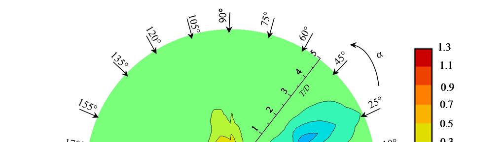
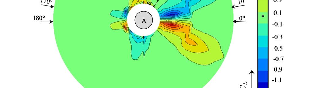
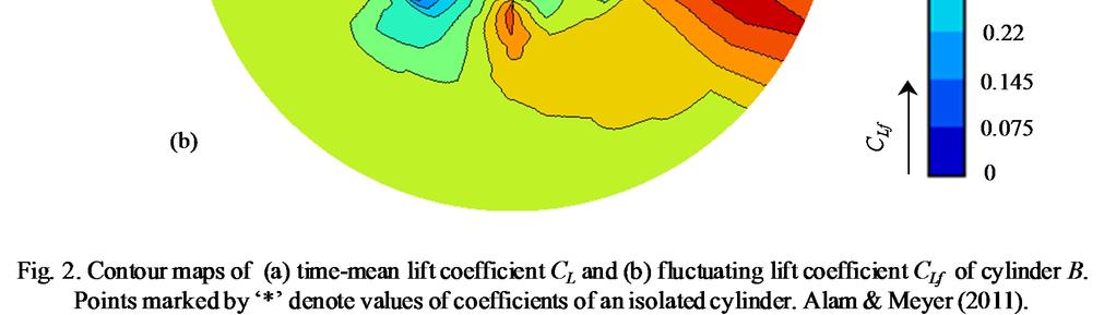
6 170, and 180, for the spacing ratio of T/D = 0.1 ~ 5. Tuning of T/D was T/D = 0.1, 0.2, 0.3, 0.5, 0.6, 0.7, 0.8, 0.9, 1.1, 1.2, 1.5, 1.8, 2.1, 2.4, 2.7, 3.0, 3.5, 4.0, 4.5 and 5.0. Flow visualization was carried out in a water channel with a mm working section and 1.5 m in length. Two circular tubes with identical diameters of 20 mm were used. The Reynolds number in the water channel experiment was 350. The flow was visualized by using the hydrogen bubble technique, involving a platinum wire of 0.02 mm in diameter. 3. Lift forces Time-averaged lift coefficient (C L ) and fluctuating (rms) lift coefficient (C Lf ) are measured of the traversing cylinder (cylinder B) for the whole ranges of a and T/D mentioned in section 2. Contours of measured C L and C Lf in a T/D - a plane are presented in Fig. 2. In the scale bars, the color or the range marked by black * indicates the value of a single isolated cylinder. The result can be described with reference to Fig. 1 in which Cylinder A is fixed, and traversing of Cylinder B is done with variation of the two parameters T/D and a, which suffice to determine the possible arrangement of the two cylinders. It may be noted that Cylinder B acts as the downstream cylinder for a < 90 and the upstream cylinders for a > 90, i.e. the left and right sides of a contour map show the values of coefficient of the upstream and downstream cylinders, respectively. At the peripheries of the middle and outer circles, the values of T/D are 0.0 and 5.0, respectively. Upward (+ve y-direction) C L is considered as positive. The C L in the downstream region (right half) is highly sensitive to T/D and a; however, that in the upstream region (left half) retains single-cylinder values except for a = , T/D < , and a = , T/D < The C L around the cylinder for T/D < 0.5 varies greatly with change in a from 0 to 360. The minimum (most negative) values of C L = and ~ occur at a = 155, T/D = 0.3 and a = 10, T/D = 0.8 ~ 1.1, respectively. At the respective conjugate positions, C L increases to a maximum. On the other hand, C Lf is extremely small for smaller spacing, i.e., T/D < 2-3 depending on a (Fig. 2(b)) and remarkably high for a = -35 to 35, T/D > Hence the interference between the cylinders not only has a negative effect with increasing forces, but also a positive effect with reducing 6
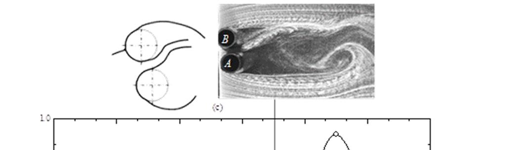
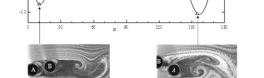
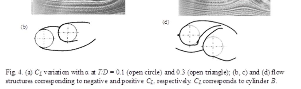
7 forces on the cylinder. Its effect, however, depends on a and T/D. It is expected that at different values of T/D and a, interaction mechanisms between the cylinders will be different, hence C L and C Lf are strong functions of T/D and a. 4. Interaction Mechanisms Though a cylinder is called a wake generator, it normally generates not only a wake but also boundary layers, shear layers, and vortices. When one cylinder is neighbored by another, the two cylinders may be connected or interacted by boundary layers, shear layer, vortex and wake. Therefore it is possible that a cylinder may experience complex interaction mechanisms where cylinder, boundary layer, shear layer, vortex and wake are the five physical interacting parameters. Based on interaction mechanisms, the whole region of a and T/D, can be classified into seven regimes as illustrated in Fig No interaction regime Here the cylinder acts independently - like a single cylinder - and is not interfered by the other (Fig. 3(b)). This happens for a» 45 ~ 180, T/D >1.3-5 depending on a. The values of drag, lift and Strouhal number are the same as those of a single isolated cylinder Boundary-layer (BL) and cylinder interaction regime Interaction between boundary layer and cylinder is generally strong and afoot when the two cylinders are very close T/D < depending on a. Interacting with the other cylinder, the boundary layer of a cylinder may form separation bubbles, delay to separate, reattach, bifurcate, swerve, switch, etc (Fig. 3(c)). Therefore the interaction not only intensifies C L but also causes a bistable nature of flow (Alam and Meyer 2011). Figure 4 displays how strong the dependence of C L on a is. As α increases from 0 to 180, C L is negative for 0 < a < 45 with a minimum at a = 10, positive for 45 < a < depending on T/D and then again negative for < a < 180, with a global maximum and minimum at a = 135 and a = 155 for T/D = 0.1 and 0.3, respectively. The adhered flow structures explain why C L follows such a trend. For 0 < a < 45, the boundary layer from the upper side of cylinder A reattaches on the upper side of cylinder B and bifurcates (Fig. 4(b)). One part goes to the lower side and 7
8 travels for a longer peripheral length before its separation, producing a net anticlockwise circulation, thus corresponding to the negative C L. Furthermore, the reattachment point corresponds to the stagnation point; hence a relatively positive pressure occurs on the upper side which also contributes to the negative C L. With increase in a up to 90 the lateral gap between the cylinders increases, hence the stagnation point moves to the lower side (Alam et al. 2003a; Alam and Zhou 2007), producing positive C L (Fig. 4(c)). A further increase in a corresponds to a decrease in the lateral gap. Therefore, pushed back by cylinder A, the lower boundary layer of cylinder B reattaches on the rear surface of the same cylinder, (Fig. 4(d)), forming a separation bubble. A large negative pressure is in general accompanied by a separation bubble. Hence the net lift is downward, negative Shear-layer/wake and cylinder interaction regime The interaction occurs when two cylinders are nearly in tandem, a» 0 ~ 20, 0.3 < T/D < The shear layer(s) from one cylinder directly interact(s) on the other cylinder surface by reattaching, impinging, forming a separation bubble, etc. Naturally, one of the cylinders is completely or partially submerged in the wake of the other, hence it can also be termed wake and cylinder interaction (Figs. 3d-f). C Lf is small at this regime except at a small island (T/D = 1~2, a» 0 ) where C Lf is slightly higher. While the small C Lf corresponds to a steady reattachment of the upstream-cylinder shear layer(s) on the downstream cylinder (Figs. 3d, f), the other is ascribed to an alternating reattachment (Fig. 3(e)). Thus a strong interaction between shear-layer and cylinder takes place. Being completely or partially submerged in the wake of the other, the cylinder acting as a stabiliser suppresses the flow unsteadiness between the cylinders (Figs. 3d, f). This regime corresponds to high C L because the high velocity slice of the upstream shear layer goes beneath the downstream cylinder (Fig. 3(d)) Shear layer (SL) and shear layer (SL) interaction regime This interaction occurs at slightly higher a than shear-layer/wake and cylinder interaction. Here the shear layer(s) of one cylinder directly interact(s) with that of the other (Fig. 3(g)). The interaction causes intermittent interlock-in of the shear layers, hence generating vortices at more than one frequency 8
9 (Alam and Sakamoto 2005), and reducing both fluctuating and mean forces on the cylinders. The two shear layers interact with themselves and the outer-shear layers Vortex and cylinder interaction regime This interaction takes place at a» -20 ~ 20, T/D > The critical spacing is T/D = 3 at a» 0, decreasing to 2 as a increases to 20. When T/D is greater than the critical spacing of two nearly in-line cylinders, the shear layers of the upstream cylinder cannot reach the downstream cylinder, hence they roll between the cylinders, forming alternate vortices (Alam et al, 2003b). The alternate vortices from the upstream cylinder subsequently strike on the downstream cylinder and embrace the side surface during passing on the cylinder (Fig. 3(h)). This interaction is generally very strong, and it intensifies fluctuating lift and drag significantly Vortex and shear-layer (SL) interaction regime The interaction happens at a» 20 ~ 35, T/D > 2.1. For this large a, the downstream cylinder becomes offset from the inner row of vortices from the upstream cylinder. The result is that, the vortices cannot interact with the downstream cylinder, but they can interact with the inner-shear layer of the downstream cylinder. Interacting with the shear layer while it is growing, the vortices force the shear layer to form a synchronized coupled vortex (Fig. 3(i)). This interaction renders a very high fluctuating lift, as alternate interaction between vortex and shear layer intervenes Vortex and vortex interaction regime For a further increase in a, the transverse distance between the cylinders becomes large, and each cylinder forms a separate wake immediately behind them (Fig. 3(j-l)). The vortices on the two inner rows interact with each other and combine the two wakes into a wider one, which results in a slightly higher fluctuating lift and drag. 5. Flow-induced instability How the interactions affect flow-induced instability of the twin cylinders - compared to a single isolated (non-interfering) cylinder - is of great interest to researchers in science and engineering. This 9
10 section includes an overview of flow-induced vibration results for two elastically mounted cylinders. The detailed results of cylinder responses at different interaction regimes are presented in Fig. 5. While the vertical axis of the response curves represents the vibration amplitude a normalized by D, the horizontal axis is U r. The response curves were incorporated from Bokaian and Geoola (1984a, b), Kim et al. (2009) and Alam and Kim (2009), yet mostly from the latter two. The dashed line in the response graphs stands for single isolated cylinder response, insinuating VE at U r» 5.4 (»1/St = 1/0.186). While both cylinders experience divergent galloping vibration for U r > 10 at 0 < a < 25 (Fig. 5(a, d)) in the boundary layer and cylinder interaction regime, they experience VE between U r = 7 to 10 for 25 < a < 155 (Fig. 5(b, c)). For the latter case, the downstream cylinder vibration amplitude is larger than the upstream one. Divergent violent vibrations of both cylinders are generated in the regime of shear-layer/wake and cylinder interaction (Fig. 5(e, f, n, o)). VE and galloping are combined at smaller T/D (Fig. 5(e, o)) and separated for larger T/D (Fig. 5(f)). High amplitude VE is afoot in the regimes of vortex and cylinder interaction (Fig. 5(g)) and vortex and shear-layer interaction (Fig. 5(h)), where C Lf on stationary cylinders is high (Fig. 2(b)). In the SL and SL interaction regime, VE occurs at two regimes of U r (Fig. 5(i, l)). Each cylinder sheds vortices at two frequencies (Alam and Sakamoto 2005), hence experiences two VE. In the vortex and vortex interaction regime, VE intervenes at a high U r for the downstream cylinder (Fig. 5(j)) and at a low U r for the upstream cylinder (Fig. 5(k)). This is due to the fact that the downstream and upstream cylinders generally shed vortices at a low and at a high frequency, respectively. The no interaction regime corresponds to VE at the same U r as that of a single cylinder (Fig. 5(m)). It is worth mentioning that a larger C Lf (Fig. 2(b)) corresponds to larger amplitude VE (Fig. 5(c, g, h)). The most striking feature is that divergent galloping vibration is generated at shear layer/wake and cylinder interaction (Fig. 5(e, f, n, o)) and at boundary layer and cylinder interaction (Fig. 5(a, d)) regimes where there is a large variation in C L in the cross-flow direction (Fig. 2(a)). Based on galloping theories it is an acknowledged fact that galloping is not generated on an axis-symmetric body, e.g. a circular cylinder. Hence the question arises, why do two circular cylinders in close proximity experience galloping? In the 10
11 regimes of boundary layer and cylinder interaction as well as shear -layer/wake and cylinder interaction, the two cylinders are connected by boundary layer or shear layer, and the combined shape of the two cylinders is not longer axis symmetric, hence the two cylinders may be prone to generating galloping vibrations. Furthermore, due to having non-uniform velocity between the cylinders, the downstream cylinder is again not axis symmetric with respect to local approaching flow. In other words, the galloping generation for two circular cylinders at close proximity is not violating the galloping theories. Details of the instability mechanism are discussed in the next section with reference to the lift force and interaction mechanisms. 6. Mechanism of Instability Figure 6 shows C L variation with change in y/d at x/d = 2. C L is maximum and minimum when y/d = and 0.4, respectively. These two y/d values correspond to the locations of positive and negative peaks in the C L contour map (Fig. 2(a)). The figure suggests that when the cylinder position is below the center line (y/d = 0), C L is in an upward direction; and when the cylinder position is above the center line, C L is in a downward direction. Now it is possible to get C L / ( y / D). Figure 7 shows how C L / ( y / D) varies with y/d. It is clear that the system is stable for y/d = -0.4 ~ 0.4 and unstable for y/d > 0.4, following quasi-steady assumption. In the former region, our intuition is confirmed: in the case of the tandem cylinder (y/d = 0), when the downstream cylinder is displaced in the transverse direction away from y/d = 0 line, there is a restoring lift force that is acting to return the cylinder to its original position (see Fig. 6). Hence quasi-steady arguments, as used in galloping theory, suggest stability of the downstream cylinder rather than instability. Galloping type response however occurs at y/d = ~ 0.4 (Fig. 5). Why and how? At y/d = 0, C L = 0 (Fig. 6), there is no force to displace the cylinder in a transverse direction. But for y/d 0, C L 0, i.e., a force exists to displace the cylinder from its neutral position. Cylinder motion is thus generated, though displacement may be very small. It does not matter in which direction the displacement occurs. The question that now arises is how an initial displacement for y/d = 0 occurs. Indeed, y/d = 0 is the critical geometry between staggered configurations of y/d = 0+ and y/d =
12 For y/d = 0+, only the upper shear layer of the upstream cylinder reattaches onto the upper surface of the downstream cylinder; for y/d = 0-, only the lower shear layer of the upstream cylinder reattaches onto the lower surface of the downstream cylinder. Hence, for y/d = 0, the upper and lower shear layers of the upstream cylinder reattach alternately onto the upper and lower surfaces of the downstream cylinder, respectively, especially for T/D smaller than critical spacing. This alternating reattachment generates fluctuating forces to displace the cylinder. When the cylinder is slightly displaced (Fig. 8(a)), the reattached shear layer is in a hesitating position, critically hovering to go on the upper side or the lower side. Instability is thus generated. For a cylinder spacing larger than critical, the oncoming vortex also has two options of where to go, on the upper side and lower side (Fig. 8(b)). This hesitation is responsible for generating the instability. 7. Conclusions Time-mean lift, fluctuating lift, flow structures and the flow-induced responses of two circular cylinders are hooked up with mechanisms of interaction between the cylinders for all possible arrangements. The current investigation has led to the conclusions below. Fluid dynamics around two cylinders is classified into seven based on how the two cylinders interact with each other. The seven occur at seven different interaction regimes, namely no interaction regime; boundary layer and cylinder interaction regime; SL/wake and cylinder interaction regime; SL and SL interaction regime; vortex and cylinder interaction regime; vortex and SL interaction regime; and vortex and vortex interaction regime. Each of them has different traits and is connected to a different flow-induced response. While forces and flow-induced responses are similar to those of a single isolated cylinder in the no interaction regime, lift force is intensified and galloping vibration is generated in the boundary layer and cylinder interaction regime. In the SL/wake and cylinder interaction regime, lift varies briskly with a or y/d, fluctuating lift is reduced and galloping vibration is generated, in addition to VE. Two VEs occur at two different reduced velocities in the SL and SL interaction regime. Both vortex and cylinder interaction and vortex and shear layer interaction causes extensively high fluctuating lift, 12
13 generating relatively high amplitude VE. The VE-reduced velocity is slightly higher for the vortex and cylinder interaction than for the vortex and shear layer interaction. Vortex and vortex interaction results in a slightly higher fluctuating lift and generates VE only. Though a single non-interfering circular cylinder does not experience galloping, two circular cylinders incur violent galloping vibration due to SL/wake and cylinder interaction as well as boundary layer and cylinder interaction. A stronger fluctuating lift corresponds to a larger vibration VE. References Alam, M.M., Kim, S., Free vibration of two identical circular cylinders in staggered arrangement. Fluid Dynamic Research 41, , 17pp. Alam, M.M., Meyer, J.P., Two interacting cylinders in cross flow. Physical Review E 84, , pp.16. Alam, M.M., Moriya, M., Sakamoto, H., 2003a. Aerodynamic characteristics of two side-by-side circular cylinders and application of wavelet analysis on the switching phenomenon. Journal of Fluids and Structures 18, Alam, M.M., Moriya, M., Takai, K., Sakamoto, H., 2003b. Fluctuating fluid forces acting on two circular cylinders in a tandem arrangement at a subcritical Reynolds number. Journal of Wind Engineering and Industrial Aerodynamics 91, Alam, M.M., Sakamoto, H., Investigation of Strouhal frequencies of two staggered bluff bodies and detection of multistable flow by wavelets. Journal of Fluids and Structures 20(3), Alam, M.M., Zhou, Y., Flow around two side-by-side closely spaced circular cylinders. Journal of Fluids and Structures 23(5), Alam, M.M., Zhou, Y., Wang, X.W., The wake of two side-by-side square cylinders. Journal of Fluid Mechanics 669, Alam, M.M., Sakamoto, H., Zhou, Y., Determination of flow configurations and fluid forces acting on two staggered circular cylinders of equal diameter in cross-flow. Journal of Fluids and Structures 13
14 21, Bokaian, A., Geoola, F., 1984a. Proximity-induced galloping of two interfering circular cylinders. Journal of Fluid Mechanics 146, Bokaian, A., Geoola, F., 1984b. Wake-induced galloping of two interfering circular cylinders. Journal of Fluid Mechanics 146, Brika, D., Laneville, A., Vortex-induced oscillations of two flexible circular cylinders coupled mechanically. Journal of Wind Engineering and Industrial Aerodynamics 69-71, Brika, D., Laneville, A., The flow interaction between a stationary cylinder and a downstream flexible cylinder. Journal of Fluids and Structures 13, Gu, Z., Sun, T., On interference between two circular cylinders in staggered arrangement at high subcritical Reynolds numbers. Journal of Wind Engineering and Industrial Aerodynamics 80, Hover, F.S., Triantafyllou, M.S., Galloping response of a cylinder with upstream wake interference. Journal of Fluids and Structures 15, Huera-Huarte, F.J. and Bearman P.W., Vortex and wake-induced vibrations of a tandem arrangement of two flexible circular cylinders with near wake interference. Journal of Fluids and Structures 27, Kim, S., Alam, M. M., Sakamoto, H., Zhou, Y., Flow-induced vibrations of two circular cylinders in tandem arrangement, Part 1: characteristics of vibration. Journal of Wind Engineering and Industrial Aerodynamics 97, Kim, S., Alam, M.M., Sakamoto, H., Zhou, Y., Flow-induced vibrations of two circular cylinders in tandem arrangement, Part 2: suppression of vibration. Journal of Wind Engineering and Industrial Aerodynamics 97, Laneville, A., Brika, D., The fluid and mechanical coupling between two circular cylinders in tandem arrangement. Journal of Fluids and Structures 13,
15 Novak, M., Aeroelastic galloping of prismatic bodies. ASCE Journal of the Engineering Mechanics. Division 96, Novak, M., Galloping oscillations of prismatic structures. ASCE Journal of the Engineering Mechanics. Division 98, Parkinson, G., Smith J., The square cylinder as an aeroelastic non-linear oscillator Quarterly Journal of Mechanics and Applied Mathematics 17, Price, S.J., Paidoussis, M.P., The aerodynamic forces acting on groups of two and three circular cylinders when subject to a cross-flow. Journal of Wind Engineering and Industrial Aerodynamics 17, Simiu, E., Scanlan, R.H., Wind Effects on Structures. Fundamentals and Applictions to Design. Wiley-IEEE, New York. Sumner, D., Price, S.J., Paidoussis, M.P., Flow-pattern identification for two staggered circular cylinders in cross-flow. Journal of Fluid Mechanics 411, Sumner, D., Two circular cylinders in cross-flow: A review. Journal of Fluids and Structures 26, Zdravkovich, M.M., The effects of interference between circular cylinders in cross flow. Journal of Fluids and Structures 1, Zdravkovich, M.M., Pridden, D.L., Interference between two circular cylinders; series of unexpected discontinuities. Journal of Industrial Aerodynamics 2,
16 List of captions Fig. 1. Arrangement of cylinders and definitions of symbols. Fig. 2. Contour maps of (a) time-mean lift coefficient C L and (b) fluctuating lift coefficient C Lf of cylinder B. Points marked by * denote values of coefficients of an isolated cylinder. Alam & Meyer (2011). Fig. 3. Interaction regimes in T/D - α plane. SL : shear layer, BL : boundary layer. Fig. 4. (a) C L variation with α at T/D = 0.1 (open circle) and 0.3 (open triangle); (b, c) and (d) flow structures corresponding to negative and positive C L, respectively. C L corresponds to cylinder B. Fig. 5. Flow-induced vibration response at different interaction regimes. Dashed line represents a single isolated cylinder response. The vertical and horizontal axes of the response graphs are the vibration amplitude ratio a/d and reduced velocity U r (= U /f n /D). The response curves are based on the results in Bokaian and Geoola (1984a, b), Kim et al. (2009), Borazjani and Sotiropoulos (2009), and Alam and Kim (2009). Fig. 6. C L variation with y/d at x/d = 2.0. Fig. 7. C L / (y/d) variation with y/d at x/d = 2.0, corresponding to an extremely slow motion, i.e., f n = very low. Fig. 8. Instability generation for (a) T/D < critical; (b) T/D > critical. 16
17 B Outer shear layer of downstream cylinder q C L C D Flow A y x a Inner shear layer of upstream cylinder Inner shear layer of downstream cylinder Outer shear layer of upstream cylinder Fig. 1. Arrangement of cylinders and definitions of symbols. 17
18 18
19 19
20 20
21 21
22 C L y/d x/d y/d C L Fig. 6. C L variation with y/d at x/d =
23 y/d C L / (y/d) Fig. 7. C L / (y/d) variation with y/d atx/d = 2.0, corresponding to an extremely slow motion, i.e., f n = very low. 23
24 (a) The shear layer is prone to switch from one side to the other Instability generated Up? Down? (b) The vortex is prone to go to the upper and lower sides Instability generated Fig. 8. Instability generation for (a) T/D < critical, (b) T/D > critical. 24
Two staggered circular cylinders of equal diameter in cross-flow
 Journal of Fluids and Structures 20 (2005) 255 276 www.elsevier.com/locate/jfs Two staggered circular cylinders of equal diameter in cross-flow D. Sumner, M.D. Richards, O.O. Akosile Department of Mechanical
Influence of rounding corners on unsteady flow and heat transfer around a square cylinder
 Influence of rounding corners on unsteady flow and heat transfer around a square cylinder S. K. Singh Deptt. of Mech. Engg., M. B. M. Engg. College / J. N. V. University, Jodhpur, Rajasthan, India Abstract
Experimental investigation of flow-induced vibration interference between two circular cylinders
 Journal of Fluids and Structures 22 (2006) 819 827 www.elsevier.com/locate/jfs Experimental investigation of flow-induced vibration interference between two circular cylinders G.R.S. Assi a, J.R. Meneghini
Investigation of Interference Effects for a Group of Finite Cylinders. 2.Tamkang University, Taipei, Taiwan ABSTRACT
 Investigation of Interference Effects for a Group of Finite Cylinders A. Kareem 1, Tracy Kijewski 1, Po-Chien Lu 2 1. University of Notre Dame, NatHaz Modeling Laboratory, Dept. of Civil Engineering and
THREE DIMENSIONAL STRUCTURES OF FLOW BEHIND A
 The Seventh Asia-Pacific Conference on Wind Engineering, November 8-12, 29, Taipei, Taiwan THREE DIMENSIONAL STRUCTURES OF FLOW BEHIND A SQUARE PRISM Hiromasa Kawai 1, Yasuo Okuda 2 and Masamiki Ohashi
THE BRIDGE COLLAPSED IN NOVEMBER 1940 AFTER 4 MONTHS OF ITS OPENING TO TRAFFIC!
 OUTLINE TACOMA NARROWS BRIDGE FLOW REGIME PAST A CYLINDER VORTEX SHEDDING MODES OF VORTEX SHEDDING PARALLEL & OBLIQUE FLOW PAST A SPHERE AND A CUBE SUMMARY TACOMA NARROWS BRIDGE, USA THE BRIDGE COLLAPSED
Proceedings of OMAE th International Conference on Offshore Mechanics and Arctic Engineering (OMAE 2005) June 12-16, 2005, Halkidiki, Greece
 June 12-16, 2005, Halkidiki, Greece") Proceedings of OMAE25 24 th International Conference on Offshore Mechanics and Arctic Engineering (OMAE 25) June 2-6, 25, Halkidiki, Greece OMAE25-672 EXPERIMENTAL INVESTIGATION OF FLOW-INDUCED VIBRATIONS
Proceedings of OMAE25 24 th International Conference on Offshore Mechanics and Arctic Engineering (OMAE 25) June 2-6, 25, Halkidiki, Greece OMAE25-672 EXPERIMENTAL INVESTIGATION OF FLOW-INDUCED VIBRATIONS
 et al. [25], Noack et al. [26] for circular cylinder flows, Van Oudheusden [27] for square cylinder and Durgesh [28] for a flat plate model. The first two modes appear as phase-shifted versions of each
Quantification of the Effects of Turbulence in Wind on the Flutter Stability of Suspension Bridges
 Quantification of the Effects of Turbulence in Wind on the Flutter Stability of Suspension Bridges T. Abbas 1 and G. Morgenthal 2 1 PhD candidate, Graduate College 1462, Department of Civil Engineering,
VORTEX SHEDDING AND VORTEX FORMATION FROM A PAIR OF IN-LINE FORCED OSCILLATING TANDEM ARRANGED CIRCULAR CYINDERS IN A UNIFORM FLOW
 5 th International Symposium on Flow Visualization June 5-8,, Minsk, Belarus VORTEX SHEDDING AND VORTEX FORMATION FROM A PAIR OF IN-LINE FORCED OSCILLATING TANDEM ARRANGED CIRCULAR CYINDERS IN A UNIFORM
EFFECT OF CORNER CUTOFFS ON FLOW CHARACTERISTICS AROUND A SQUARE CYLINDER
 EFFECT OF CORNER CUTOFFS ON FLOW CHARACTERISTICS AROUND A SQUARE CYLINDER Yoichi Yamagishi 1, Shigeo Kimura 1, Makoto Oki 2 and Chisa Hatayama 3 ABSTRACT It is known that for a square cylinder subjected
Computation of Flow Behind Three Side-by-Side Cylinders of Unequal/Equal Spacing
 Computation of Flow Behind Three Side-by-Side Cylinders of Unequal/Equal Spacing H. K. Virahsawmy 1, L. Chen 2, I. R. MacGillivray 2, J. Tu 1 and Y. Zhou 3 1. School of Aerospace, Mechanical and Manufacturing
Experimental Investigation Of Flow Past A Rough Surfaced Cylinder
 (AET- 29th March 214) RESEARCH ARTICLE OPEN ACCESS Experimental Investigation Of Flow Past A Rough Surfaced Cylinder Monalisa Mallick 1, A. Kumar 2 1 (Department of Civil Engineering, National Institute
Aerodynamic Measures for the Vortex-induced Vibration of π-shape Composite Girder in Cable-stayed Bridge
 Aerodynamic Measures for the Vortex-induced Vibration of π-shape Composite Girder in Cable-stayed Bridge *Feng Wang 1), Jialing Song 2), Tuo Wu 3), and Muxiong Wei 4) 1), 2, 3), 4) Highway School, Chang
PRESSURE FLUCTUATIONS ACTING ON A TAPERED TALL BUILDING
 The Seventh Asia-Pacific Conference on Wind Engineering, November 8-12, 29, Taipei, Taiwan PRESSURE FLUCTUATIONS ACTING ON A TAPERED TALL BUILDING Young-Moon Kim 1, Ki-Pyo You 1, Jang-Youl You 2 and Chang-Hyun
EXPERIMENTAL ANALYSIS OF THE CONFLUENT BOUNDARY LAYER BETWEEN A FLAP AND A MAIN ELEMENT WITH SAW-TOOTHED TRAILING EDGE
 24 TH INTERNATIONAL CONGRESS OF THE AERONAUTICAL SCIENCES EXPERIMENTAL ANALYSIS OF THE CONFLUENT BOUNDARY LAYER BETWEEN A FLAP AND A MAIN ELEMENT WITH SAW-TOOTHED TRAILING EDGE Lemes, Rodrigo Cristian,
EXPERIMENTAL STUDY OF WIND PRESSURES ON IRREGULAR- PLAN SHAPE BUILDINGS
 BBAA VI International Colloquium on: Bluff Bodies Aerodynamics & Applications Milano, Italy, July, 2-24 8 EXPERIMENTAL STUDY OF WIND PRESSURES ON IRREGULAR- PLAN SHAPE BUILDINGS J. A. Amin and A. K. Ahuja
The effect of back spin on a table tennis ball moving in a viscous fluid.
 How can planes fly? The phenomenon of lift can be produced in an ideal (non-viscous) fluid by the addition of a free vortex (circulation) around a cylinder in a rectilinear flow stream. This is known as
SPECTRAL CHARACTERISTICS OF FLUCTUATING WIND LOADS ON A SEPARATE TWIN-BOX DECK WITH CENTRAL SLOT
 The Seventh Asia-Pacific Conference on Wind Engineering, November 8-, 009, Taipei, Taiwan SPECTRAL CHARACTERISTICS OF FLUCTUATING WIND LOADS ON A SEPARATE TWIN-BOX DEC WITH CENTRAL SLOT Le-Dong Zhu, Shui-Bing
Hydrodynamic Forces acting on Two Flexible Free-hanging Cantilevers in Tandem Configurations due to Cross-flows
 162 IPTEK, The Journal for Technology and Science, Vol. 2, No. 4, November 29 Hydrodynamic Forces acting on Two Flexible Free-hanging Cantilevers in Tandem Configurations due to Cross-flows Rudi Walujo
JOURNAL PUBLICATIONS
 1 JOURNAL PUBLICATIONS 71. Lee, T., Mageed, A., Siddiqui, B. and Ko, L.S., (2016) Impact of ground proximity on aerodynamic properties of an unsteady NACA 0012 airfoil, submitted to Journal of Aerospace
RESILIENT INFRASTRUCTURE June 1 4, 2016
 RESILIENT INFRASTRUCTURE June 1 4, 2016 CASE STUDIES ON THE IMPACT OF SURROUNDING BUILDINGS ON WIND-INDUCED RESPONSE John Kilpatrick Rowan Williams Davies and Irwin, Guelph, Ontario, Canada ABSTRACT In
Geometry Modification For Minimizing The Aeroelastics Effect
 Geometry Modification For Minimizing The Aeroelastics Effect Fariduzzaman a, Subagyo a, Fadilah Hasim a and Matza Gusto Andika a a Aero-Gas dynamics and Vibration Laboratory (LAGG), BPPT, PUSPIPTEK, Serpong
Tim Lee s journal publications
 Tim Lee s journal publications 82. Lee, T., and Tremblay-Dionne, V., (2018) Impact of wavelength and amplitude of a wavy ground on a static NACA 0012 airfoil submitted to Journal of Aircraft (paper in
Keywords: dynamic stall, free stream turbulence, pitching airfoil
 Applied Mechanics and Materials Vol. 225 (2012) pp 103-108 Online available since 2012/Nov/29 at www.scientific.net (2012) Trans Tech Publications, Switzerland doi:10.4028/www.scientific.net/amm.225.103
EXPERIMENTAL INVESTIGATION OF WAKE SURVEY OVER A CYLINDER WITH DIFFERENT SURFACE PROFILES
 EXPERIMENTAL INVESTIGATION OF WAKE SURVEY OVER A CYLINDER WITH DIFFERENT SURFACE PROFILES Abdul Ahad Khan 1, Abhishek M. B 2, Tresa Harsha P George 3 1 Under Graduate student, Department of Aeronautical
SEMI-SPAN TESTING IN WIND TUNNELS
 25 TH INTERNATIONAL CONGRESS OF THE AERONAUTICAL SCIENCES SEMI-SPAN TESTING IN WIND TUNNELS S. Eder, K. Hufnagel, C. Tropea Chair of Fluid Mechanics and Aerodynamics, Darmstadt University of Technology
AERODYNAMIC CHARACTERISTICS OF SPIN PHENOMENON FOR DELTA WING
 ICAS 2002 CONGRESS AERODYNAMIC CHARACTERISTICS OF SPIN PHENOMENON FOR DELTA WING Yoshiaki NAKAMURA (nakamura@nuae.nagoya-u.ac.jp) Takafumi YAMADA (yamada@nuae.nagoya-u.ac.jp) Department of Aerospace Engineering,
An Experimental Study of Vortex Shedding Behind a Bluff Body in a Water Channel
 An Experimental Study of Vortex Shedding Behind a Bluff Body in a Water Channel ¹Meghanadhan C A, ² Sunil A S ¹PG Scholar, ² Associate Prof. Govt Engineering College Thrissur, Kerala,India Abstract-When
Experimental investigation on the aerodynamic loads and wake flow features of low aspect-ratio triangular prisms at different wind directions
 Journal of Fluids and Structures 25 (2009) 1119 1135 www.elsevier.com/locate/jfs Experimental investigation on the aerodynamic loads and wake flow features of low aspect-ratio triangular prisms at different
The Effect of Von Karman Vortex Street on Building Ventilation
 The Effect of Von Karman Vortex Street on Building Ventilation P.Praveen Kumar Abstract This paper deals with the utilisation of the von Karman vortex street principle to maximise air flow into buildings.
Experimental investigation on the influence of wind direction on the aerodynamic loads acting on low aspect-ratio triangular prisms
 Experimental investigation on the influence of wind direction on the aerodynamic loads acting on low aspect-ratio triangular prisms Giacomo Valerio Iungo and Guido Buresti Department of Aerospace Engineering,
AE Dept., KFUPM. Dr. Abdullah M. Al-Garni. Fuel Economy. Emissions Maximum Speed Acceleration Directional Stability Stability.
 Aerodynamics: Introduction Aerodynamics deals with the motion of objects in air. These objects can be airplanes, missiles or road vehicles. The Table below summarizes the aspects of vehicle performance
NUMERICAL SIMULATION OF ACTIVE FLOW CONTROL BASED ON STREAMWISE VORTICES FOR A BLUNT TRAILING EDGE AIRFOIL
 BBAA VI International Colloquium on: Bluff Bodies Aerodynamics & Applications Milano, Italy, July, 20-24 2008 NUMERICAL SIMULATION OF ACTIVE FLOW CONTROL BASED ON STREAMWISE VORTICES FOR A BLUNT TRAILING
NUMERICAL SIMULATION OF CROSS-FLOW AROUND FOUR CIRCULAR CYLINDERS IN-LINE SQUARE CONFIGURATION NEAR A PLANE WALL
 NUMERICAL SIMULATION OF CROSS-FLOW AROUND FOUR CIRCULAR CYLINDERS IN-LINE SQUARE CONFIGURATION NEAR A PLANE WALL A. Grummy Wailanduw 1, Triyogi Yuwono 2 and Wawan Aries Widodo 2 1 Student of Doctoral Program
Effects of seam and surface texture on tennis balls aerodynamics
 Available online at www.sciencedirect.com Procedia Engineering 34 (2012 ) 140 145 9 th Conference of the International Sports Engineering Association (ISEA) Effects of seam and surface texture on tennis
The Effect of Spacing on the Vortex-Induced Vibrations of Two Tandem Flexible Cylinders
 The Effect of Spacing on the Vortex-Induced Vibrations of Two Tandem Flexible Cylinders Enhao Wang, Qing Xiao, Qiang Zhu and Atilla Incecik NOTICE: this is the author s version of a work that was accepted
THE TACOMA NARROWS BRIDGE FAILURE Revision A
 By Tom Irvine Email: tomirvine@aol.com December 29, 1999 THE TACOMA NARROWS BRIDGE FAILURE Revision A Introduction The original Tacoma Narrows Bridge was opened to traffic on July 1, 1940. It was located
FLUID FORCE ACTING ON A CYLINDRICAL PIER STANDING IN A SCOUR
 BBAA VI International Colloquium on: Bluff Bodies Aerodynamics & Applications Milano, Italy, July, 20-24 2008 FLUID FORCE ACTING ON A CYLINDRICAL PIER STANDING IN A SCOUR Takayuki Tsutsui Department of
AERODYNAMICS I LECTURE 7 SELECTED TOPICS IN THE LOW-SPEED AERODYNAMICS
 LECTURE 7 SELECTED TOPICS IN THE LOW-SPEED AERODYNAMICS The sources of a graphical material used in this lecture are: [UA] D. McLean, Understanding Aerodynamics. Arguing from the Real Physics. Wiley, 2013.
Experimental investigation on the aft-element flapping of a two-element airfoil at high attack angle
 Experimental investigation on the aft-element flapping of a two-element airfoil at high attack angle Tan Guang-kun *, Shen Gong-xin, Su Wen-han Beijing University of Aeronautics and Astronautics (BUAA),
Journal of Engineering Science and Technology Review 9 (5) (2016) Research Article. CFD Simulations of Flow Around Octagonal Shaped Structures
 (2016) Research Article. CFD Simulations of Flow Around Octagonal Shaped Structures") Jestr Journal of Engineering Science and Technology Review 9 (5) (2016) 72-76 Research Article JOURNAL OF Engineering Science and Technology Review www.jestr.org CFD Simulations of Flow Around Octagonal
Jestr Journal of Engineering Science and Technology Review 9 (5) (2016) 72-76 Research Article JOURNAL OF Engineering Science and Technology Review www.jestr.org CFD Simulations of Flow Around Octagonal
Wind tunnel effects on wingtip vortices
 48th AIAA Aerospace Sciences Meeting Including the New Horizons Forum and Aerospace Exposition 4-7 January 2010, Orlando, Florida AIAA 2010-325 Wind tunnel effects on wingtip vortices Xin Huang 1, Hirofumi
WIND-INDUCED LOADS OVER DOUBLE CANTILEVER BRIDGES UNDER CONSTRUCTION
 WIND-INDUCED LOADS OVER DOUBLE CANTILEVER BRIDGES UNDER CONSTRUCTION S. Pindado, J. Meseguer, J. M. Perales, A. Sanz-Andres and A. Martinez Key words: Wind loads, bridge construction, yawing moment. Abstract.
A Study on Roll Damping of Bilge Keels for New Non-Ballast Ship with Rounder Cross Section
 International Ship Stability Workshop 2013 1 A Study on Roll Damping of Bilge Keels for New Non-Ballast Ship with Rounder Cross Section Tatsuya Miyake and Yoshiho Ikeda Department of Marine System Engineering,
STUDIES ON THE OPTIMUM PERFORMANCE OF TAPERED VORTEX FLAPS
 ICAS 2000 CONGRESS STUDIES ON THE OPTIMUM PERFORMANCE OF TAPERED VORTEX FLAPS Kenichi RINOIE Department of Aeronautics and Astronautics, University of Tokyo, Tokyo, 113-8656, JAPAN Keywords: vortex flap,
Unsteady airfoil experiments
 Unsteady airfoil experiments M.F. Platzer & K.D. Jones AeroHydro Research & Technology Associates, Pebble Beach, CA, USA. Abstract This paper describes experiments that elucidate the dynamic stall phenomenon
CIRCULATION PRODUCTION AND SHEDDING FROM VERTICAL AXIS WIND TURBINE BLADES UNDERGOING DYNAMIC STALL
 June 3 - July 3, 5 Melbourne, Australia 9 7D-3 CIRCULATION PRODUCTION AND SHEDDING FROM VERTICAL AXIS WIND TURBINE BLADES UNDERGOING DYNAMIC STALL Abel-John Buchner,,, Julio Soria,3, Alexander J. Smits,
The Seventh International Colloquium on Bluff Body Aerodynamics and Applications (BBAA7) Shanghai, China; September 2-6, 2012 Wind tunnel measurements
 Shanghai, China; September 2-6, 2012 Wind tunnel measurements") The Seventh International Colloquium on Bluff Body Aerodynamics and Applications (BBAA7) Shanghai, China; September 2-6, 2012 Wind tunnel measurements of aeroelastic guyed mast models a, Tomasz Lipecki
The Seventh International Colloquium on Bluff Body Aerodynamics and Applications (BBAA7) Shanghai, China; September 2-6, 2012 Wind tunnel measurements of aeroelastic guyed mast models a, Tomasz Lipecki
Australian Journal of Basic and Applied Sciences. Pressure Distribution of Fluid Flow through Triangular and Square Cylinders
 AENSI Journals Australian Journal of Basic and Applied Sciences ISSN:1991-8178 Journal home page: www.ajbasweb.com Pressure Distribution of Fluid Flow through Triangular and Square Cylinders 1 Nasaruddin
Investigation of Suction Process of Scroll Compressors
 Purdue University Purdue e-pubs International Compressor Engineering Conference School of Mechanical Engineering 2006 Investigation of Suction Process of Scroll Compressors Michael M. Cui Trane Jack Sauls
Chapter 15 Wave Motion. Copyright 2009 Pearson Education, Inc.
 Chapter 15 Wave Motion 15-1 Characteristics of Wave Motion All types of traveling waves transport energy. Study of a single wave pulse shows that it is begun with a vibration and is transmitted through
Waves. harmonic wave wave equation one dimensional wave equation principle of wave fronts plane waves law of reflection
 Waves Vocabulary mechanical wave pulse continuous periodic wave amplitude wavelength period frequency wave velocity phase transverse wave longitudinal wave intensity displacement wave number phase velocity
DYAMIC BEHAVIOR OF VORTEX SHEDDING FROM AN OSCILLATING THREE-DIMENSIONAL AIRFOIL
 27 TH INTERNATIONAL CONGRESS OF THE AERONAUTICAL SCIENCES DYAMIC BEHAVIOR OF VORTEX SHEDDING FROM AN OSCILLATING THREE-DIMENSIONAL AIRFOIL Hiroaki Hasegawa*, Kennichi Nakagawa** *Department of Mechanical
Preliminary design of a high-altitude kite. A flexible membrane kite section at various wind speeds
 Preliminary design of a high-altitude kite A flexible membrane kite section at various wind speeds This is the third paper in a series that began with one titled A flexible membrane kite section at high
Unsteady Wave-Driven Circulation Cells Relevant to Rip Currents and Coastal Engineering
 Unsteady Wave-Driven Circulation Cells Relevant to Rip Currents and Coastal Engineering Andrew Kennedy Dept of Civil and Coastal Engineering 365 Weil Hall University of Florida Gainesville, FL 32611 phone:
EXPERIMENTAL STUDY ON THE HYDRODYNAMIC BEHAVIORS OF TWO CONCENTRIC CYLINDERS
 EXPERIMENTAL STUDY ON THE HYDRODYNAMIC BEHAVIORS OF TWO CONCENTRIC CYLINDERS *Jeong-Rok Kim 1), Hyeok-Jun Koh ), Won-Sun Ruy 3) and Il-Hyoung Cho ) 1), 3), ) Department of Ocean System Engineering, Jeju
The Aerodynamic Drag of Parafoils
 The Aerodynamic Drag of Parafoils A. C. Carruthers and A. Filippone The University of Manchester Manchester M60 1QD United Kingdom Introduction The parafoil is an aerodynamic decelerator that uses the
Wind-Induced Oscillations Parametric Wind Tunnel Test
 National Aeronautics and Space Administration Wind-Induced Oscillations Parametric Wind Tunnel Test Sam Yunis, Donald Keller, Thomas Ivanco, Jennifer Pinkerton NASA Langley Presented at Spacecraft and
Chapter 2. Turbulence and the Planetary Boundary Layer
 Chapter 2. Turbulence and the Planetary Boundary Layer In the chapter we will first have a qualitative overview of the PBL then learn the concept of Reynolds averaging and derive the Reynolds averaged
Effect of a rigid wall on the vortex induced vibration of two staggered circular cylinders
 Effect of a rigid wall on the vortex induced vibration of two staggered circular cylinders Javad Farrokhi Derakhshandeh a), Maziar Arjomandi, Benjamin S. Cazzolato and Bassam Dally Abstract School of Mechanical
Wind Tunnel Study on Spanwise Correlation of Aerodynamic Forces on a 5:1 Rectangular Cylinder
 The Eighth Asia-Pacific Conference on Wind Engineering, December 10 1, 2013, Chennai, India Wind Tunnel Study on Spanwise Correlation of Aerodynamic Forces on a 5:1 Rectangular Cylinder Xiaobing Liu 1,
Wind Flow Validation Summary
 IBHS Research Center Validation of Wind Capabilities The Insurance Institute for Business & Home Safety (IBHS) Research Center full-scale test facility provides opportunities to simulate natural wind conditions
Inlet Influence on the Pressure and Temperature Distortion Entering the Compressor of an Air Vehicle
 Distortion Entering the Compressor of an Air Vehicle P. Hendrick Université Libre de Bruxelles, ULB Avenue F.D. Roosevelt, 50 1050 Brussels BELGIUM patrick.hendrick@ulb.ac.be ABSTRACT One of the possible
PRESSURE DISTRIBUTION OF SMALL WIND TURBINE BLADE WITH WINGLETS ON ROTATING CONDITION USING WIND TUNNEL
 International Journal of Mechanical and Production Engineering Research and Development (IJMPERD ) ISSN 2249-6890 Vol.2, Issue 2 June 2012 1-10 TJPRC Pvt. Ltd., PRESSURE DISTRIBUTION OF SMALL WIND TURBINE
MEASUREMENTS ON THE SURFACE WIND PRESSURE CHARACTERISTICS OF TWO SQUARE BUILDINGS UNDER DIFFERENT WIND ATTACK ANGLES AND BUILDING GAPS
 BBAA VI International Colloquium on: Bluff Bodies Aerodynamics & Applications Milano, Italy, July, 2-24 28 MEASUREMENTS ON THE SURFACE WIND PRESSURE CHARACTERISTICS OF TWO SQUARE BUILDINGS UNDER DIFFERENT
High Swept-back Delta Wing Flow
 Advanced Materials Research Submitted: 2014-06-25 ISSN: 1662-8985, Vol. 1016, pp 377-382 Accepted: 2014-06-25 doi:10.4028/www.scientific.net/amr.1016.377 Online: 2014-08-28 2014 Trans Tech Publications,
Transverse waves cause particles to vibrate perpendicularly to the direction of the wave's motion (e.g. waves on a string, ripples on a pond).
.") Waves Introduction A vibration must be the source of a wave. Waves in turn also cause vibrations. They are intrinsically connected. Waves transmit energy. There are different ways in which waves can be
Waves Introduction A vibration must be the source of a wave. Waves in turn also cause vibrations. They are intrinsically connected. Waves transmit energy. There are different ways in which waves can be
Wave Motion. interference destructive interferecne constructive interference in phase. out of phase standing wave antinodes resonant frequencies
 Wave Motion Vocabulary mechanical waves pulse continuous periodic wave amplitude period wavelength period wave velocity phase transverse wave longitudinal wave intensity displacement amplitude phase velocity
Journal of Engineering Science and Technology Review 6 (3) (2013) Research Article
 (2013) Research Article") Jestr Journal of Engineering Science and Technology Review 6 (3) (013) 105-110 Research Article JOURNAL OF Engineering Science and Technology Review www.jestr.org Lift and Drag on Cylinder of Octagonal
Jestr Journal of Engineering Science and Technology Review 6 (3) (013) 105-110 Research Article JOURNAL OF Engineering Science and Technology Review www.jestr.org Lift and Drag on Cylinder of Octagonal
Chapter 11 Waves. Waves transport energy without transporting matter. The intensity is the average power per unit area. It is measured in W/m 2.
 Energy can be transported by particles or waves: Chapter 11 Waves A wave is characterized as some sort of disturbance that travels away from a source. The key difference between particles and waves is
The Effect of Gurney Flap Height on Vortex Shedding Modes Behind Symmetric Airfoils
 The Effect of Gurney Flap Height on Vortex Shedding Modes Behind Symmetric Airfoils Daniel R. Troolin 1, Ellen K. Longmire 2, Wing T. Lai 3 1: TSI Incorporated, St. Paul, USA, dan.troolin@tsi.com 2: University
THEORETICAL EVALUATION OF FLOW THROUGH CENTRIFUGAL COMPRESSOR STAGE
 THEORETICAL EVALUATION OF FLOW THROUGH CENTRIFUGAL COMPRESSOR STAGE S.Ramamurthy 1, R.Rajendran 1, R. S. Dileep Kumar 2 1 Scientist, Propulsion Division, National Aerospace Laboratories, Bangalore-560017,ramamurthy_srm@yahoo.com
AERODYNAMIC CHARACTERISTICS OF NACA 0012 AIRFOIL SECTION AT DIFFERENT ANGLES OF ATTACK
 AERODYNAMIC CHARACTERISTICS OF NACA 0012 AIRFOIL SECTION AT DIFFERENT ANGLES OF ATTACK SUPREETH NARASIMHAMURTHY GRADUATE STUDENT 1327291 Table of Contents 1) Introduction...1 2) Methodology.3 3) Results...5
Visual Observation of Nucleate Boiling and Sliding Phenomena of Boiling Bubbles on a Horizontal Tube Heater
 Proceedings of the 2 nd World Congress on Mechanical, Chemical, and Material Engineering (MCM'16) Budapest, Hungary August 22 23, 216 Paper No. HTFF 146 DOI:.11159/htff16.146 Visual Observation of Nucleate
A Study on the Effects of Wind on the Drift Loss of a Cooling Tower
 A Study on the Effects of Wind on the Drift Loss of a Cooling Tower Wanchai Asvapoositkul 1* 1 Department of Mechanical Engineering, Faculty of Engineering, King Mongkut s University of Technology Thonburi
INTERFERENCE EFFECT AND FLOW PATTERN OF FOUR BIPLANE CONFIGURATIONS USING NACA 0024 PROFILE
 Proceedings of the International Conference on Mechanical Engineering 211 (ICME211) 18-2 December 211, Dhaka, Bangladesh ICME11-FL-1 INTERFERENCE EFFECT AND FLOW PATTERN OF FOUR BIPLANE CONFIGURATIONS
Computational Investigation of Airfoils with Miniature Trailing Edge Control Surfaces
 AIAA-24-5 Computational Investigation of Airfoils with Miniature Trailing Edge Control Surfaces Hak-Tae Lee, Ilan M. Kroo Stanford University, Stanford, CA 9435 Abstract Miniature trailing edge effectors
A comparison of NACA 0012 and NACA 0021 self-noise at low Reynolds number
 A comparison of NACA 12 and NACA 21 self-noise at low Reynolds number A. Laratro, M. Arjomandi, B. Cazzolato, R. Kelso Abstract The self-noise of NACA 12 and NACA 21 airfoils are recorded at a Reynolds
INTERNATIONAL JOURNAL OF CIVIL AND STRUCTURAL ENGINEERING Volume 1, No 4, 2010
 Effect of geometric dimensions on the transmission coefficient of floating breakwaters Mohammad Hosein Tadayon, Khosro Bargi 2, Hesam Sharifian, S. Reza Hoseini - Ph.D student, Department of Civil Engineering,
Methods The experiments were carried out in the wind tunnel in the Air physics laboratory at the Engineering Centre Bygholm as shown in figure 1.
 1 Standardisation of test method for salt spreader: Air flow experiments Report 2: Visualization of airflow patterns by Jan S. Strøm, Consultant Aarhus University, Engineering Centre Bygholm, Test and
COURSE NUMBER: ME 321 Fluid Mechanics I Fluid statics. Course teacher Dr. M. Mahbubur Razzaque Professor Department of Mechanical Engineering BUET
 COURSE NUMBER: ME 321 Fluid Mechanics I Fluid statics Course teacher Dr. M. Mahbubur Razzaque Professor Department of Mechanical Engineering BUET 1 Fluid statics Fluid statics is the study of fluids in
Lecture # 08: Boundary Layer Flows and Drag
 AerE 311L & AerE343L Lecture Notes Lecture # 8: Boundary Layer Flows and Drag Dr. Hui H Hu Department of Aerospace Engineering Iowa State University Ames, Iowa 511, U.S.A y AerE343L #4: Hot wire measurements
Pressure coefficient on flat roofs of rectangular buildings
 Pressure coefficient on flat roofs of rectangular buildings T. Lipecki 1 1 Faculty of Civil Engineering and Architecture, Lublin University of Technology, Poland. t.lipecki@pollub.pl Abstract The paper
Asymmetric vortex shedding flow past an inclined flat plate at high incidence
 Title Asymmetric vortex shedding flow past an inclined flat plate at high incidence Author(s) Lam, KM; Leung, MYH Citation European Journal Of Mechanics, B/Fluids, 5, v. 4 n., p. - 48 Issued Date 5 URL
Lesson 14: Simple harmonic motion, Waves (Sections )
") Circular Motion and Simple Harmonic Motion The projection of uniform circular motion along any ais (the -ais here) is the same as simple harmonic motion. We use our understanding of uniform circular motion
Circular Motion and Simple Harmonic Motion The projection of uniform circular motion along any ais (the -ais here) is the same as simple harmonic motion. We use our understanding of uniform circular motion
DESIGN AND CHARACTERISTICS OF A LARGE BOUNDARY- LAYER WIND TUNNEL WITH TWO TEST SECTIONS
 The Seventh Asia-Pacific Conference on Wind Engineering, November 8-12, 2009, Taipei, Taiwan DESIGN AND CHARACTERISTICS OF A LARGE BOUNDARY- LAYER WIND TUNNEL WITH TWO TEST SECTIONS Kai Chen 1, Xin-Yang
Gravity waves in stable atmospheric boundary layers
 Gravity waves in stable atmospheric boundary layers Carmen J. Nappo CJN Research Meteorology Knoxville, Tennessee 37919, USA Abstract Gravity waves permeate the stable atmospheric planetary boundary layer,
Inlet Swirl on Turbocharger Compressor Performance
 Inlet Swirl on Turbocharger Compressor Performance Lei Huang, Ying Liu, Hua Chen* National laboratory of Engine Turbocharging Technology, Tianjin, China *corresponding author: Tel.:+86-22-5870-7069; fax:
INTERACTION BETWEEN WIND-DRIVEN AND BUOYANCY-DRIVEN NATURAL VENTILATION Bo Wang, Foster and Partners, London, UK
 INTERACTION BETWEEN WIND-DRIVEN AND BUOYANCY-DRIVEN NATURAL VENTILATION Bo Wang, Foster and Partners, London, UK ABSTRACT Ventilation stacks are becoming increasingly common in the design of naturally
Citation Journal of Thermal Science, 18(4),
,") NAOSITE: Nagasaki University's Ac Title Author(s) Noise characteristics of centrifuga diffuser (Noise reduction by means leading tip) Murakami, Tengen; Ishida, Masahiro; Citation Journal of Thermal Science,
NAOSITE: Nagasaki University's Ac Title Author(s) Noise characteristics of centrifuga diffuser (Noise reduction by means leading tip) Murakami, Tengen; Ishida, Masahiro; Citation Journal of Thermal Science,
CRITERIA OF BOW-DIVING PHENOMENA FOR PLANING CRAFT
 531 CRITERIA OF BOW-DIVING PHENOMENA FOR PLANING CRAFT Toru KATAYAMA, Graduate School of Engineering, Osaka Prefecture University (Japan) Kentarou TAMURA, Universal Shipbuilding Corporation (Japan) Yoshiho
Aerodynamic Terms. Angle of attack is the angle between the relative wind and the wing chord line. [Figure 2-2] Leading edge. Upper camber.
![Aerodynamic Terms. Angle of attack is the angle between the relative wind and the wing chord line. [Figure 2-2] Leading edge. Upper camber.](/thumbs/82/86661300.jpg "Aerodynamic Terms. Angle of attack is the angle between the relative wind and the wing chord line. [Figure 2-2] Leading edge. Upper camber.") Chapters 2 and 3 of the Pilot s Handbook of Aeronautical Knowledge (FAA-H-8083-25) apply to powered parachutes and are a prerequisite to reading this book. This chapter will focus on the aerodynamic fundamentals
Chapters 2 and 3 of the Pilot s Handbook of Aeronautical Knowledge (FAA-H-8083-25) apply to powered parachutes and are a prerequisite to reading this book. This chapter will focus on the aerodynamic fundamentals
KARMAN VORTEX (KV) AND IMPINGING SHEAR LAYER VORTEX (IMPV)
 AND IMPINGING SHEAR LAYER VORTEX (IMPV)") The 2012 World Congress on Advances in Civil, Environmental, and Materials Research (ACEM 12) Seoul, Korea, August 26-30, 2012 ROLE OF Karman VORTEX ON BLUFF BODY AERODYNAMICS- VORTEX-INDUCED VIBRATION
The 2012 World Congress on Advances in Civil, Environmental, and Materials Research (ACEM 12) Seoul, Korea, August 26-30, 2012 ROLE OF Karman VORTEX ON BLUFF BODY AERODYNAMICS- VORTEX-INDUCED VIBRATION
Experimental Investigation of End Plate Effects on the Vertical Axis Wind Turbine Airfoil Blade
 Experimental Investigation of End Plate Effects on the Vertical Axis Wind Turbine Airfoil Blade Rikhi Ramkissoon 1, Krishpersad Manohar 2 Ph.D. Candidate, Department of Mechanical and Manufacturing Engineering,
CFD AND EXPERIMENTAL STUDY OF AERODYNAMIC DEGRADATION OF ICED AIRFOILS
 Colloquium FLUID DYNAMICS 2008 Institute of Thermomechanics AS CR, v.v.i., Prague, October 22-24, 2008 p.1 CFD AND EXPERIMENTAL STUDY OF AERODYNAMIC DEGRADATION OF ICED AIRFOILS Vladimír Horák 1, Dalibor
EXPERIMENTAL ANALYSIS OF FLOW OVER SYMMETRICAL AEROFOIL Mayank Pawar 1, Zankhan Sonara 2 1,2
 EXPERIMENTAL ANALYSIS OF FLOW OVER SYMMETRICAL AEROFOIL Mayank Pawar 1, Zankhan Sonara 2 1,2 Assistant Professor,Chandubhai S. Patel Institute of Technology, CHARUSAT, Changa, Gujarat, India Abstract The
Available online at Procedia Engineering 200 (2010) (2009) In situ drag measurements of sports balls
 (2009) In situ drag measurements of sports balls") Available online at www.sciencedirect.com Procedia Engineering 200 (2010) (2009) 2437 2442 000 000 Procedia Engineering www.elsevier.com/locate/procedia 8 th Conference of the International Sports Engineering
Available online at www.sciencedirect.com Procedia Engineering 200 (2010) (2009) 2437 2442 000 000 Procedia Engineering www.elsevier.com/locate/procedia 8 th Conference of the International Sports Engineering
Experimental Study of Flow around a Circular Cylinder inside a Bubble Plume
 Advances in Chemical Engineering and Science, 2016, 6, 269-280 Published Online July 2016 in SciRes. http://www.scirp.org/journal/aces http://dx.doi.org/10.4236/aces.2016.63027 Experimental Study of Flow
Flow and Mixing in the Liquid between Bubbles
 Excerpt from the Proceedings of the COMSOL Conference 2009 Boston Flow and Mixing in the Liquid between Bubbles Bruce A. Finlayson, Professor Emeritus of Chemical Engineering Department of Chemical Engineering,