|
|
|
- Silvester Hampton
- 5 years ago
- Views:
Transcription


1 1
2 2
3 CONTENTS INTRODUCTION Owner Information 4 Warranty Registration 5 Safety Instructions Safety 6 Safety Decals 7 Safety Identification Labels 8 Safety Notice 10 Safety Standards 11 Risk Assessment 13 INSTALLATION Installation 15 Circuit Diagram 20 OPERATION AND ATTACHING Operation Guide 21 Connection Test 23 Checking Attachments and Buckets 24 MAINTENANCE General Maintenance 26 Weekly Checks hr Preventative Maintenance 28 Maintenance & Repair Log 33 Torque Specifications 34 Parts Drawing 35 Parts List 36 Cylinder Parts Drawing 37 Cylinder Parts List 38 Multi-Coupler Series 1C Specifications 39 3
4 INTRODUCTION OWNER INFORMATION Thank you for choosing to purchase your new Calibre Multi-Coupler (Multi-Coupler) from Calibre Contracting Equipment s (Calibre) range of earthmoving products. This manual contains important information about the installation, maintenance and safe operation of your Multi-Coupler. You can assist in this proactive safety approach by ensuring that all persons involved with the fitting and operation of the Multi-Coupler, read and understand these basic safety features and instructions. Calibre reserves the right of modification as a result of further technical developments with regard to the information and illustrations cited in this manual: Calibre and its suppliers have sole copyright of this manual The manual is intended solely for the use of the Multi-Coupler No part of this manual may be reprinted, translated or reproduced by any means without prior written permission from Calibre Utilisation for the purposes of competition is forbidden The Multi-Coupler is designed for safe and dependable service if installed, maintained and operated correctly We request that time be devoted to the study of installation and maintenance requirements. Users are also expected to familiarise themselves with the correct operation and use of the Multi-Coupler and its advised safety procedures. IMPORTANT NOTE To comply with Occupational Safety and Health requirements, a record must be made of all repairs, adjustments and regular maintenance events involving your Multi-Coupler. 4
5 INTRODUCTION WARRANTY REGISTRATION Upon purchasing your Multi-Coupler please complete and return this form immediately to your local Calibre branch. DATE OF DELIVERY: SERIAL NUMBER: I confirm that the operator(s) of the relevant excavator has read and understands the Operating Instructions and Warranty Terms, which relate to the Multi-Coupler. The Operator accepts that he/ she is responsible for understanding safety and operation features of the Multi-Coupler. NAME: POSITlON: COMPANY: SIGNATURE: THE PURCHASER SHALL: Follow the recommended installation, testing and maintenance and operating procedures Comply with safety and training guidelines for use of equipment (not totally exclusive) Keep an accurate maintenance, operation, malfunction and repair log of equipment Ensure that the equipment is used for the purpose it was intended for 5


6 SAFETY INSTRUCTIONS SAFETY Incorrect It is your responsibility to observe pertinent laws and regulations and follow Calibre instructions for operation and maintenance. Calibre supplies a standard Multi-Coupler to fit Calibre approved attachments. However when tilting a non standard attachment check the operation fitting guide for the attachment s pin range and width to suit the Multi-Coupler model. NOTE: The Multi-Coupler has a maximum and minimum pin centre travel range. Please refer to the attached badge on the Multi-Coupler for this information. 6

7 SAFETY DECALS SAFETY INSTRUCTIONS 7


8 SAFETY INSTRUCTIONS SAFETY IDENTIFICATION LABELS The pin centre range displays the minimum and maximum travel distance for each slide hook on the Multi-Coupler. All attachments must be within the parameters of these measurements identifed on the label. The label also identifes the slide hook type. CALIBRE PART NO. All Calibre Multi-Couplers have an identifcation label with the machine model recorded. 8


9 SAFETY INSTRUCTIONS Only lift from Lifting Eye situated on the rear of the Muti-Coupler 1. Ensure that the load to be lifted does not exceed the safe working load of the Lifting Eye or the machine to which it is fitted. 2. The Lifting Eye is to be used with a certi ed lifting shackle with the same or greater safe working load. 3. S.W.L - Safe Working Load is stamped on the Lifting Eye and the Multi-Coupler is fitted with a label on the side that specifies maximum working load. 4. Lifting Eye has to be visually inspected daily. 9


10 SAFETY NOTICE SAFETY INSTRUCTIONS The Certified Lifting Eye must be used accordingly to the following guidelines: Only use the Lifting Eye at the rear of the coupler for lifting Do not lift with bucket or any other attachment fitted to the Multi-Coupler Ensure that the load to be lifted does not exceed the rated W.L.L of the Multi-Coupler and Lifting Eye The Lifting Eye is to be used with a certified Lifting Eye with the same or greater safe working load Lifting must be carried out with the coupler in a vertical plane so that the load can hang free without interfering with the coupler body Lifting Eye must be visually inspected daily for defects and wear The below sticker MUST be permanently fixed to the operator s cab in a clearly visible location SAFETY NOTICE Display in the cab visible to the Operator at all times CORRECT OPERATION OF LIFTING EYE Lifting Eye must be in a VERTICAL PLANE with the shackle hanging free of all obstruction DO NOT lift if the chain & shackle interfere with the Coupler Lift in a vertical plane ONLY Shackle MUST hang freely DO: + Must comply with Approved Code of Practice for Cranes & all other regulations relating to the use of Cranes + Only use Lifting Eye on Coupler + Only uses associated with primary function of Excavator + Only use in accordance with Calibre Operating Manual (To be stored in cab at all times) DO NOT: + Exceed lifting capacity (specified in certificate & hard stamped on the Lifting Eye) + Use with any other Attachment on Excavator Note: Check Lifting Eye & Coupler structure for wear, cracks & damage daily in accordance with Calibre Operation Manual.. Calibre Operation Manual must be safely stored in cab at all times. 10
11 STANDARDS SAFETY STANDARDS Only the following competent persons may work independently with any of type of Calibre earthmoving attachments. Operators must possess the following: Over 18 years of age Highly competent Are physically and intellectually able Have been instructed in the general regulations concerning operational safety and particularly accident prevention Have been instructed in assembly, operation and maintenance of earthmoving machinery and using the Multi-Coupler system. They must understand these operating instructions and have proven to the contractor that they are capable of operating such machinery Ensure that only authorised personnel work with the Multi-Coupler Only give instructions to competent and skilled personnel NOTE: For Calibre products supplied to or manufactured in countries other than New Zealand and Australia, the rules for prevention of accidents and safety regulations for the respective country must be strictly adhered to. 11
12 STANDARDS STANDARDS AND OCCUPATIONAL SAFETY AND HEALTH GUIDELINES The standards and Occupational Safety and Health Guidelines for the Calibre Multi-Coupler are as follows: AS Standards Australia. Australian standard for - Earthmoving Machinery - Multi-Couplers (couplers) for excavators and backhoe loaders - AS section C AS Cranes (Including hoists and winches) Part 5: Mobile vehicle loading cranes. European Standard EN474-5; Section /2 and 3. Electrical Interlocking for Safety in Industrial Processes. Standard Operating Guidelines for Plant and Machinery. We request that time be devoted to the study of installation and maintenance requirements. Users are also expected to familiarise themselves with the correct operation and use of the Multi-Coupler, and its advised safety procedures. ASSOCIATED STANDARDS AS 2954 Earthmoving Equipment - Rated Loads and Volumetric ratings AS 2954 Earthmoving Equipment - Tests and Measurements AS 2954 Earthmoving Equipment - Instrumentation and Control AS 2954 Earthmoving Equipment - Operation and Maintenance AS 2954 Earthmoving Equipment - Safety Excavator and attachments must be suitable or converted for mounting the Calibre Multi-Coupler (in agreement with Calibre). The crowd and breakout forces speci ed by the excavator manufacturer must not be exceeded. The Calibre Multi-Coupler must not be used for impact work (only with attachments specified for this). Load hook rating must never be exceeded. Adherence to the specifications in this manual is part of the intended use. All Calibre Multi-Coupler models have specific safety features, see those that relate to your purchase. 12
13 RISK ASSESSMENT Location: Date: Ref no: Hazards Identified: Work equipment Lifting devices Ergonomics Entanglement Crushing Access / exit Slip, trip and fall Plant movement Warning devices on equipment Noise Vibration Fumes Environmental People Affected YES NO N/A Involved in activity Close to activity Everyone on site Members of the public Expected Precautions YES NO N/A Has the operator been adequately trained on the use of the Multi-Coupler in general? Is the operator competent in using the specific attachment on the machine? Is there a system for checking that the attachment pins are in place on the Multi-Coupler prior to work starting everytime a different attachment is fitted? Is the operator aware that they must not operate the machine unless they are satisfied that Multi-Coupler is secured in place? Does the view of the operator from inside the cab allow them to visually see that the Multi-Coupler is secured in place? Does the Multi-Coupler have the approved labels stating and referring to attachment specifications? Is there a risk assessment for the Multi-Coupler detachment? Is there a checklist of daily and weekly inspections? Is there cab instructions for the Multi-Coupler? Personal Protective Equipment (PPE) Hard Hat High Visibility Vest Safety Boots Gloves Ear Protection Safety Glasses Other Management Assessed by: Name: Date: Reported to: Name: Date 13
14 RISK ASSESSMENT Operator s Name: Calibre Serial No.: Calibre Contracting Equipment Model: Date: In Cab Multi-Coupler Operating Controls (Alarm, warning light, switch) Operating Instructions (labels) Operating & Maintenance Manual M O N T U E W E D T H U F R I S A T S U N Hydraulic System Wear or damage to hoses or fittings Security of hoses Hydraulic oil leaks Coupler Wear and damage to bucket / attachment pins and retainers Security of mounting pins, locking bolts and nuts Is the attachment safe to use? YES or NO Lubrication Greasing in accordance with Calibre instructions Operator Signature Manager Signature 14
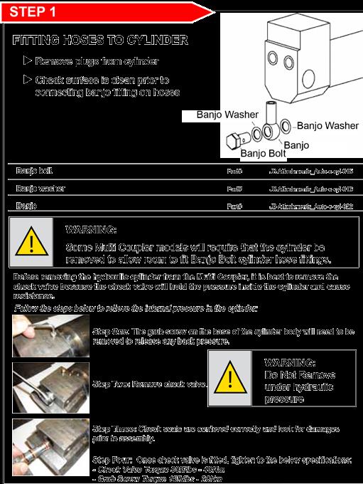
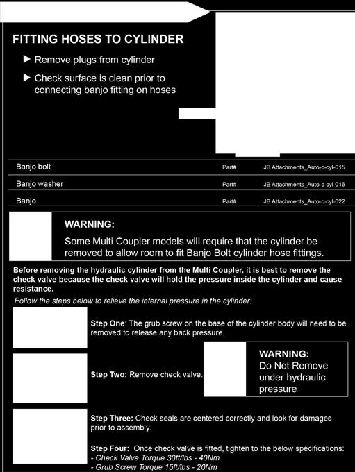
15 INSTALLATION Calibre_Auto-c-cyl-015 Calibre_Auto-c-cyl-016 Calibre_Auto-c-cyl


16 INSTALLATION Align Calibre Multi-Coupler to the dipper arm and fit o-ring seals and shims where required Install original equipment manufacturer s harden fix spacing pins to attach Calibre Multi-Coupler to dipper arm on excavator. Fit locking bolts and nuts to secure pins. 16


17 INSTALLATION - - Coupler or Tilt Bucket Tilt Multi- 17
18 18 INSTALLATION

19 INSTALLATION - 19


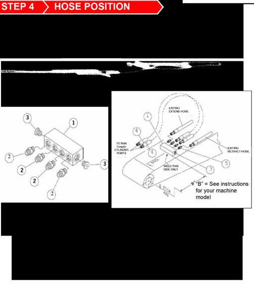
20 CIRCUIT DIAGRAM INSTALLATION Please ensure that during installation of a Calibre Multi-Coupler the pressure in the hydraulic circuit is checked and set at: 20
21 OPERATION AND ATTACHING OPERATION GUIDE 21


22 22 OPERATION AND ATTACHING


23 OPERATION AND ATTACHING OPERATION GUIDE 23


24 OPERATION AND ATTACHING WARNING: Check pin centres of Calibre Multi-Coupler for all customer s attachments centre pin-centre - B) Check the width of each attachment. Where there is an excessive gap - (exceeding 10mm), spacers can be fitted to better suit the Multi-Coupler to the attachment. Spacers can be fitted to either the base of the Multi-Coupler or between the inner side of the ears and the bosses of attachment. It is especially advisable to fit spacers in the case of heavier applications, particularly on machines that are 10 ton and above. 24

 This should be in the range specified on Calibre Serial Tag If Pin Diameter or Pin Centres do not match with the Calibre Serial Tag, safe operation could be seriously impaired.")
25 OPERATION AND ATTACHING Ensure the correct attachments and buckets are used with Calibre Multi-Coupler in accordance with the specifications on the Calibre Multi-Coupler / Power-Tilt Serial Tag. Measure the diameter of the pin on attachment (image 1.0) This should be the same as stated on the Calibre Serial Tag Use a ruler to check pin centres of all attachments being used (image 2.0) This should be in the range specified on Calibre Serial Tag If Pin Diameter or Pin Centres do not match with the Calibre Serial Tag, safe operation could be seriously impaired. You need to stop using the attachment until changes are made to match attachment to Calibre Multi-Coupler. If you require assistance to resolve this issue, please call Calibre. 25
26 MAINTENANCE GENERAL MAINTENANCE WARNING - Maintenance Work Maintenance work must be completed by competent personnel or assistance requested from Calibre DANGER - Hydraulic Fluid Never use hands to search for hydraulic fluid leaks, use a piece of paper or cardboard. Escaping fluid under pressure can be invisible and can penetrate the skin and cause serious injury. If affected, see a doctor straight away. WARNING - Multi-Coupler Condition A defective Multi Coupler could injure you or others. Do not operate a Multi-Coupler that is defective. WARNING - Hose Arrangement Ensure that the hoses are not too loose and do not come into contact with the spring mechanisms as this will prevent the safe operation of the blocking bar. Maintenance and Service To ensure that your Multi-Coupler works safely and to maximum eficiency it is imperative that it is properly maintained in accordance with the following service guidelines. Replacement Parts We recommend that you fit genuine replacement parts. You will need to quote the Multi-Coupler serial number stamped on the Multi-Coupler data plate when ordering replacement parts. DAILY CHECKS 1) Complete Multi-Coupler Pre-Start Check sheet on Page 3.3 of this Operation Manual. 2) Grease Multi-Coupler regularly (minimum of once per week). It is important that all parts are greased. 3) Check Lifting Eye for damage. If in doubt do not use. 26
. If damaged, replace and grease.")
27 MAINTENANCE WEEKLY CHECKS It is recommended that the following procedures are carried out at least once per week. 1. Carry out all daily, checks (refer to Page for guide). 2. Lubrication points - Ensure that all grease points are greased regularly (at least once a week minimum). If damaged, replace and grease. It is important to follow the lubrication instructions in sequence, so none of the grease nipples are overlooked. i. Release the bucket/attachment (refer to the operation instructions-section). ii. Retract the Multi-Coupler cylinder. Switch off the engine. iii. Apply grease, via grease nipple (refer to image 1.1 and 1.2). iv. Apply grease via nipple to the hook (refer to image 1.1). v. Start the engine. Extend the bucket cylinder in order to position the Multi-Coupler so that the cylinder grease nipples are accessible. Switch off the engine. It is essential that this log is filled in at the time of carrying out maintenance or repair on the Multi- Coupler. In the unfortunate event of an accident, this log may be vital evidence as to compliance with Occupational Safety and Health requirements. Work carried out on this Calibre Multi-Coupler must only be by an authorised and competent person. 27

28 MAINTENANCE Should you find any cracks anywhere on the Multi-Coupler body, contact your local Calibre branch or authorised Service Centre immediately. 28

29 MAINTENANCE - Should you find any cracks anywhere on the Multi-Coupler body, contact your local Calibre branch or authorised Service Centre immediately. 29


30 MAINTENANCE If the Multi-Coupler frame becomes worn or damaged in this area on the side frame (image 2), contact your local Calibre branch or authorised Service Centre immediately. 30

31 MAINTENANCE Manual Inspection of Calibre Multi-Coupler Safety-Latch is to be carried out to ensure safety-latch movement is within acceptable safety tolerances as specified below. This is in addition to daily visual check of safety-latch and usual wear-andtear assessments. Connect Calibre Multi-Coupler to attachment with slide fully retracted to lock safety-latch. If the Maximum Opening Distance is greater than the Maximum Allowable Opening value for that Calibre Multi-Coupler model, safe operation of the Calibre Multi-Coupler could be seriously impaired. Please contact Calibre Service department for advice. 31


32 MAINTENANCE - C02 C03 C04 C06 C08 C14 C20 C35 Should you find any cracks anywhere on the Lifting Eye, contact your local Calibre branch or authorised Service Centre immediately. 32
33 MAINTENANCE MAINTENANCE & REPAIR LOG DATE FAULT REPAIR BY WHOM 33
34 34 MAINTENANCE
35 MAINTENANCE 35
36 36 MAINTENANCE
37 MAINTENANCE NOTE: Cylinder design is different for each model 37
38 38 MAINTENANCE

39 MAINTENANCE 39
40 40
41 CALIBRE Contracting Equipment Australia 59 Magnesium Drive, Crestmead, Australia CALIBRE Contracting Equipment New Zealand 49 McLaughlins Road, Wiri, Auckland
FRONT & REAR LOCK OPERATION & MAINTENANCE MANUAL
 RAM-TILT COUPLER Imagery does not reflect actual product size FRONT & REAR LOCK OPERATION & MAINTENANCE MANUAL CONTENTS INTRODUCTION Owner Information 4 Warranty Registration 5 Key Features 6 Ram-Tilt
OPERATION & MAINTENANCE MANUAL
 THUMB Imagery does not reflect actual product size T2017A OPERATION & MAINTENANCE MANUAL 1 2 T2017A CONTENTS INTRODUCTION Owner Information 5 Warranty Registration 6 Key Features 7 To the Owner 8 SAFETY
Werk-Brau D-Lock Coupler Installation and Operation Manual
 Werk-Brau D-Lock Coupler Installation and Operation Manual SERIAL NUMBER: The D-Lock Coupler (Fully Automatic with Dual Pin Locking) International Patents pending IMPORTANT: The booklet should be kept
LIFTING RIG Multi-Product Installation Rig
 VISUAL INSPECTION CONDITION REPORT Review Date: Dec 13 LIFTING RIG Multi-Product Installation Rig Equipment Number Customer Dispatch/Receipt Date Out / / Date In / / Store Location Expected Return Date
MODEL SWH10 1,000 LB CAPACITY SWIVEL HOIST
 MODEL SWH10 1,000 LB CAPACITY SWIVEL HOIST PARTS BREAKDOWN AND OPERATING MANUAL Copyright 2007, Arcan Professional Tools Rev: 05/15/07 This operating manual contains important safety information. Read
REL-46 WARNING NOTICE 15 TON SINGLE ACTING REMOTE HYDRAULIC CRIMPING HEAD. Compatible with RELIABLE R15 and P Style dies. REL-46 Manual
 OPERATORS ORS GUIDE REL-46 15 TON SINGLE ACTING REMOTE HYDRAULIC CRIMPING HEAD Compatible with RELIABLE R15 and P Style dies. RELIABLE EQUIPMENT & SERVICE CO., INC. 301 Ivyland Road Warminster, PA 18974
CULTIVATOR SAFETY SECTION
 CULTIVATOR SAFETY SECTION The above safety-alert symbol means ATTENTION! Be Alert! Your personal safety is involved This symbol draws your attention to important instructions concerning your personal safety.
35 TON HYDRAULIC PUNCH WARNING
 OPERATORS GUIDE REL-35T-PNC 35 TON HYDRAULIC PUNCH NOTICE Sizes, weights and tool specifications listed in this manual are subject to change without notice. Please consult factory for information and updates.
310 SERIES TILT-TO-LOAD ROTATOR. The Specialist In Drum Handling Equipment
 OPERATOR S MANUAL FOR MORSE TILT-TO-LOAD DRUM ROTATOR SAFETY INFORMATION: While Morse Manufacturing Co. drum handling equipment is engineered for safety and efficiency, a high degree of responsibility
REL-510H WARNING NOTICE 12 TON SINGLE ACTING REMOTE HYDRAULIC CRIMPING HEAD
 OPERATORS ORS GUIDE REL-510H 12 TON SINGLE ACTING REMOTE HYDRAULIC CRIMPING HEAD Compatible with U style and RELIABLE R12 shell type 12 ton compression dies. RELIABLE EQUIPMENT & SERVICE CO., INC. 92 Steamwhistle
Parts & Operators Manual
 Parts & Operators Manual (888) 317-5878 www.talet.ca To The Owner General Comments Congratulations on the purchase of your new Talet Mat Grapple. Your unit was carefully designed and manufactured to give
PDY TON HYDRAULIC CRIMPING TOOL WARNING
 OPERATORS ORS GUIDE PDY-1220 12 TON HYDRAULIC CRIMPING TOOL All information found in this guide must be read and understood before use or testing of this tool. Failure to read and understand these warnings
Surface exploration drilling
 Checklist Surface exploration drilling This checklist is intended to assist employers to identify common hazards and manage risks associated with surface exploration drilling. June 2017 Background In surface
GAP Tool Box Talk: Quick Hitches
 GAP Tool Box Talk: Quick Hitches Purpose To provide information and guidance on the safe use of quick hitches To increase the awareness of operators who use mechanical plant fitted with quick hitches To
Tube-Line Accelerator Spinner Kit
 Tube-Line Accelerator Spinner Kit Operator's Manual PP-00799 (19/09/11) 2 TO THE OWNER This manual contains information concerning the adjustment, assembly and maintenance of your Tube-Line Spinner Kit.
WBM Installation Manual KAT Master Hitch
 WBM Installation Manual KAT Master Hitch General Information This section provides general information and recommendations required prior to installing, operating or maintaining your KAT Master Hitch.
30T A/Manual Hydraulic Shop Press
 30T A/Manual Hydraulic Shop Press Operation Manual 1 1. Important Information 1.1 Safety Information 1.1.1 Hazard Symbols Used in the Manuals This manual includes the hazard symbols defined below when
Model No.: SFC-ED Torque Tool Serial No.: SFC Ref No.:
 Model No.: SFC-ED Torque Tool Serial No.: SFC Ref No.: CONTENTS 1 Contents Page & Introduction 2 Training Requirements & General Safety 3 SFC ED Tool Models Covered By Manual Noise & Vibration Levels 4
Triple Tine Mechanical Grapple
 Attachment Solutions Triple Tine Mechanical Grapple Operators Manual KENCO Mechanical Grapple Operation Manual 1 TABLE OF CONTENTS 170 State Route 271 Section I. General Information.... 3 Section II. Safety...
This section provides general information and recommendations required prior to installing, operating or maintaining your KAT Master Hitch.
 WBM Parts and Installation Manual for KAT Master Hitch General Information This section provides general information and recommendations required prior to installing, operating or maintaining your KAT
SOP GEN-007X Crane and Winch Operations
 Page 1 of 7 SOP GEN-007X 1.0 Introduction 2.0 Responsibility 3.0 References 4.0 Training and Qualifications 5.0 Operational Inspections 6.0 Maintenance and Load Tests 7.0 Cranes 8.0 Winches 9.0 Mobile
REV0709. Parts List. Hydraulic Cylinder Model MODEL C SINGLE-ACTING, SPRING RETURN HYDRAULIC CYLINDER. Max. Capacity: 55.2 Tons at 10,000 PSI
 REV0709 Parts List Hydraulic Cylinder Model 10312 MODEL C SINGLE-ACTING, SPRING RETURN HYDRAULIC CYLINDER Max. Capacity: 55.2 Tons at 10,000 PSI REV0709 Item No. Part No. No. Req d Description 1 10606
Assembly, Installation and operating. instructions for. Söll-Xenon anchorage device
 Assembly, Installation and operating instructions for Söll-Xenon anchorage device according to EN 795:1996 Part No: XE-... (The following must be completed by the operator in permanent waterproof ink.)
56 Bypass Mini Grapple
 56 Bypass Mini Grapple T-1001 1 INTRODUCTION Branch Manager Attachments would like you to be completely satisfied with your new product, so please contact us for help with service, replacement parts, or
Manual winch MANISTOR 100 and 200
 Manual wall winch Manual winch MANISTOR 100 and 200 Instruction manual UK 173-192.10-3 PRODUCT DEVELOPED AND MANUFACTURED ACCORDING TO NF EN 13157 STANDARD REGISTERED DESIGN To ensure the constant improvement
Installation and Service Manual
 An Actuant Company Installation and Service Manual Heavy Duty Hydraulic Stabilization Legs CONTENTS Part # 3010003129 REV 0D Section Page 1.0 Receiving Instructions 2 2.0 Safety Issues 2 3.0 Hydraulic
SAFE WORK METHOD STATEMENT Part 1 EXCAVATOR AUGER ATTACHMENT
 SAFE WORK METHOD STATEMENT Part 1 EXCAVATOR AUGER ATTACHMENT Personal Protective Equipment Foot Hearing High Visibility Head Eye Day Operations Normal Requirements: Safety footwear, hearing protection,
M S I C R A N E S C A L E
 2 M E A S U R E M E N T S Y S T E M S I N T E R N A T I O N A L Table of Contents Forward...3 Safe Operating Guidelines...4 Operating Suggestions...4 Handling Hoist Motion...4 Safe Loading and Rigging
Name of product: Gripper for vertical façade FTV panels Types: PVF (60, 80, 100, 120, 133, 150, 172, 200 and 240 mm) INSTRUCTIONS FOR USE
 INSTRUCTIONS FOR USE") Name of product: Gripper for vertical façade FTV panels Types: PVF (60, 80, 100, 120, 133, 150, 172, 200 and 240 mm) INSTRUCTIONS FOR USE CONTENTS INTRODUCTION - GENERAL INFORMATION 3 Purpose of instructions
Name of product: Gripper for vertical façade FTV panels Types: PVF (60, 80, 100, 120, 133, 150, 172, 200 and 240 mm) INSTRUCTIONS FOR USE CONTENTS INTRODUCTION - GENERAL INFORMATION 3 Purpose of instructions
Meuangvang Development Co.LTD Standard Working Procedure 058 Use of Hydraulic Torqueing Devices
 1. Application To provide a standard work procedure for as required in accordance with Meuangvang Development Co Ltd Safety Management Program 2. Revision Schedule Rev # Old Section Ref New Section Ref
PRO Lifting Operations
 MS&L Procedure PRO-4.5-0001-1-06 Lifting Operations Document Owner: Bill Kruesi HSSE Manager - Asset Mgmt. Owen Quake ANZ Engineering Authority Approved By: Bill Kruesi HSSE Manager - Asset Mgmt. Control
20 Ton SD Shop Press Operating Instructions
 20 Ton SD Shop Press Operating Instructions MODEL NO. 850SD Hazard Symbols Used in the Manuals This manual includes the hazard symbols defined below when the operations or maintenance job involves a potential
Safety and operating instructions
 Safety and operating instructions Oil flow dividers 5, 8 www.cp.com 2 Contents Contents Introduction....................................................................... 5 About the Safety and operating
1. SAFETY 2. PREPARATION 3. FRAME 4. TRANSMISSION 5. DRIVE 6. ROW UNIT 7. OPTIONAL EQUIPMENT
 TABLE OF CONTENTS 1. SAFETY 2. PREPARATION 3. FRAME 4. TRANSMISSION 5. DRIVE 6. ROW UNIT 7. OPTIONAL EQUIPMENT This symbol means: ATTENTION - BECOME ALERT YOUR SAFETY IS INVOLVED. When you see this symbol
STEEL TRENCH SHIELDS DW MODELS
 STEEL TRENCH SHIELDS DW MODELS 3330 S. SAM HOUSTON PKWY E. HOUSTON, TEXAS 77047 Phone: 713.943.0750 Toll Free: 800.231.6662 Fax: 713. 943.8483 COPYRIGHT, U.S.A., SPEED SHORE CORPORATION, 2009 April 16,
Release: 1. UEPOPL002A Licence to operate a reciprocating steam engine
 Release: 1 UEPOPL002A Licence to operate a reciprocating steam engine UEPOPL002A Licence to operate a reciprocating steam engine Modification History Not applicable. Unit Descriptor Unit Descriptor 1)
Hazards Requiring Attention: AS AT Friday, 29 January Next Review Saturday, 28 January Total Hazards Recorded 39. Critical Risk Hazards 0
 EF26 Risk Assessment CAT Excavator Hazards Requiring Attention: AS AT Friday, 29 January 2016 0 Next Review Saturday, 28 January 2017 Total Hazards Recorded 39 Critical Risk Hazards 0 High Risk Hazards
LEVEL 2 CERTIFICATE OF COMPETENCE IN THE SAFE USE AND OPERATION OF MOBILE ELEVATED WORK PLATFORMS
 NPTC Registered Charity No. 1096429 NATIONAL AGRICULTURAL CENTRE STONELEIGH PARK, WARWICKSHIRE CV8 2LG Tel: 024 7669 6553 Fax: 024 7669 6128 Email: information@nptc.org.uk LEVEL 2 CERTIFICATE OF COMPETENCE
Hazards Requiring Attention: AS AT Friday, 1 April Next Review Saturday, 1 April Total Hazards Recorded 43. Critical Risk Hazards 0
 EF26 Risk Assessment Kubota U35-4 s Requiring Attention: AS AT Friday, 1 April 2016 0 Next Review Saturday, 1 April 2017 Total s Recorded 43 Critical Risk s 0 High Risk s 0 Moderate Risk s 10 Low Risk
CONTENTS: 57100AH 100 Ton Air/Hydraulic Shop Press OWNER'S MANUAL
 OWNER'S MANUAL CONTENTS: Page 1 Warning Information 2 Specifications, Operating Instructions and Notes 3 Inspection, Safety Instructions and Limited Warranty 4 Parts Diagram PRESS SPECIFICATIONS Sunex
Allspeeds Ltd. Royal Works, Atlas St Clayton le Moors Accrington Lancashire England BB5 5LW. Tel +44 (0)
") Allspeeds Ltd. Royal Works, Atlas St Clayton le Moors Accrington Lancashire England BB5 5LW Tel +44 (0)1254 615100 www.allspeeds.co.uk SOFT LINE CUTTER SL55 PRODUCT CODE No. 980504 INSTRUCTIONS FOR INSTALLATION,
Allspeeds Ltd. Royal Works, Atlas St Clayton le Moors Accrington Lancashire England BB5 5LW Tel +44 (0)1254 615100 www.allspeeds.co.uk SOFT LINE CUTTER SL55 PRODUCT CODE No. 980504 INSTRUCTIONS FOR INSTALLATION,
INTENDED USE TECHNICAL SPECIFICATIONS
 1/2IN. HEAVY-DUTY AIR IMPACT WRENCH OWNER S MANUAL WARNING: Read carefully and understand all INSTRUCTIONS before operating. Failure to follow the safety rules and other basic safety precautions may result
"STEEL FRAMED" ALUMINUM PANEL SHIELDS
 "STEEL FRAMED" ALUMINUM PANEL SHIELDS MANUFACTURE S TABULATED DATA 3330 S. Sam Houston Pkwy Houston, Texas 77047 (713)943-0750 USA Toll Free 1-800-231-6662 Fax (713)943-8483 Www.speedshore.com PRINTED
INSTALLATION, OPERATION AND SERVICE MANUAL ABS AIR BAG LIFT
 INSTALLATION, OPERATION AND SERVICE MANUAL ABS AIR BAG LIFT P.O. Box 1058 1058 West Industrial Avenue Guthrie, OK 73044-1058 405-282-5200 FAX: 405-282-8105 www.autoquip.com Item # 830ABS Version 1.0 07/2001
Specifications Testing & Adjusting Disassembly & Assembly
 SB4191E00 Jul. 2005 Specifications Testing & Adjusting Supplement for Quad Lift Mast D20/25/30/32/33S-3 G/GC20/25/30/32P-3 G/GC20/25/30/32E-3 Important Safety Information Most accidents involving product
Operation and Maintenance Instructions
 Hydratight Limited Bentley Road South Darlaston West Midlands WS10 8LQ United Kingdom Tel: +44 121 50 50 600 Fax: +44 121 50 50 800 E-mail: enquiry@hydratight.com Website: www.hydratight.com TOP COLLAR
DK ton, Double-acting, Die-type Crimping Tool
 INSTRUCTION MANUAL DK6040 60-ton, Double-acting, Die-type Crimping Tool Read and understand all of the instructions and safety information in this manual before operating or servicing this tool. Register
RARS5000 AIR BODY SAW OWNER S OPERATING MANUAL
 RARS5000 AIR BODY SAW OWNER S OPERATING MANUAL DESCRIPTION 1. No mar 2. No mar tip 3. Housing grip 4. Trigger 5. Air inlet 6. Air inlet plug 7. Plastic board Important! It is essential that you read the
General Information. NTA607HD Lift Assist Adjustments. Tools Required. Work Location. Notations and Conventions U B F D R B F L
 Great Plains Manufacturing, Inc. 1 NTA607HD Lift Assist Adjustments Null4: When you see this symbol, the subsequent instructions and warnings are serious - follow without exception. Your life and the lives
Operation of Embrey Excavator Shears Safe Work Procedure PTES_HSE_SWP_039. Name Date Signature. Author Jarred Hearle 27/11/2015
 Operation of Embrey Excavator Shears Safe Work Procedure PTES_HSE_SWP_039 Name Date Signature Author Jarred Hearle 27/11/2015 Reviewed FMG Site Team 27/11/2015 ---------- Approved Geoff Selfe 27/11/2015
HYDRAULIC WINCH FOR AUGERS UP TO WR10 X 71 / W130 X 41 ASSEMBLY & OPERATION MANUAL
 HYDRAULIC WINCH ASSEMBLY & OPERATION MANUAL Read this manual before using product. Failure to follow instructions and safety precautions can result in serious injury, death, or property damage. Keep manual
KRAC KC-600 PLOW OPERATOR S MANUAL
 PLOW OPERATOR S MANUAL RWF INDUSTRIES 873 Devonshire Ave., Woodstock, Ontario N4S 8Z4 Tel: (519) 421-0036 Toll Free: 1-800-263-1060 Fax: (519) 421-0028 Email: parts@rwfbron.com JANUARY 2015 THE INFORMATION
Instruction Manual. Maximum Operating Pressure 1,500 bar
 Hydraulic Bolt Tensioners Model DBT Series Maximum Operating Pressure 1,500 bar ABSOLUTE EQUIPMENT PTY LTD 2/186 Granite Street, GEEBUNG QLD 4034 Australia sales@absoluteequipment.com.au Phone: +61 7 3865
Allspeeds Ltd. Royal Works, Atlas St Clayton le Moors Accrington Lancashire England BB5 5LW. Tel +44 (0)
") Allspeeds Ltd. Royal Works, Atlas St Clayton le Moors Accrington Lancashire England BB5 5LW Tel +44 (0)1254 615100 www.allspeeds.co.uk SOFTLINE CUTTER SL80 PRODUCT CODE No. 980248 INSTRUCTIONS FOR INSTALLATION,
Allspeeds Ltd. Royal Works, Atlas St Clayton le Moors Accrington Lancashire England BB5 5LW Tel +44 (0)1254 615100 www.allspeeds.co.uk SOFTLINE CUTTER SL80 PRODUCT CODE No. 980248 INSTRUCTIONS FOR INSTALLATION,
75 Ton SD Shop Press Operating Instructions
 75 Ton SD Shop Press Operating Instructions MODEL NO. 856SD Hazard Symbols Used in the Manuals This manual includes the hazard symbols defined below when the operations or maintenance job involves a potential
SPEED SHORE MANUFACTURER S TABULATED DATA "MHS" MODELS. STEEL MANHOLE SHIELDS 4 Single Wall 4 Double Wall 4 Double Wall with Cut-Outs
 SPEED SHORE MANUFACTURER S TABULATED DATA "MHS" MODELS STEEL MANHOLE SHIELDS 4 Single Wall 4 Double Wall 4 Double Wall with Cut-Outs January 01, 2005 3330 S. SAM HOUSTON PKWY E. HOUSTON, TEXAS 77047 Tel:
CS150 CAP STAPLER OWNER S MANUAL
 Operation Revised 6/2013 www.stingerworld.com CS150 CAP STAPLER OWNER S MANUAL! Maintenance Safety Warranty PLEASE READ! This manual contains important information about product safety. WELCOME TO STINGER
OPERATOR S MANUAL SPREADER. CSS, VNQ [For Combine Harvester AW82V] Original instructions
![OPERATOR S MANUAL SPREADER. CSS, VNQ [For Combine Harvester AW82V] Original instructions](/thumbs/90/102423265.jpg "OPERATOR S MANUAL SPREADER. CSS, VNQ [For Combine Harvester AW82V] Original instructions") OPERATOR S MANUAL SPREADER CSS, VNQ [For Combine Harvester AW82V] en Original instructions Introduction Introduction Please read this operator s manual before using your spreader. We would first like to
OPERATOR S MANUAL SPREADER CSS, VNQ [For Combine Harvester AW82V] en Original instructions Introduction Introduction Please read this operator s manual before using your spreader. We would first like to
ROLLGLISS TOP/R350. Safety and rescue system. Operating and Maintenance Instructions
 ROLLGLISS TOP/R350 Safety and rescue system Operating and Maintenance Instructions Table of Contents 1 1. Safety Instructions...2 1.1 Important instructions for use of the safety and rescue systems 1.2
Equipment Operation Procedures
 Procedures Purpose It is the policy of this company to permit only trained and authorized personnel to operate construction equipment. These procedures are applicable to both daily operators, and those
SEMEMI SQA Unit Code H2B7 04 Assisting in the installation of compressed air equipment
 Assisting in the installation of compressed air equipment Overview This unit identifies the competences you need to assist in the installation of compressed air equipment and systems, in accordance with
1 DRIVE INDUSTRIAL IMPACT WRENCH
 1 DRIVE INDUSTRIAL IMPACT WRENCH 92622 ASSEMBLY AND OPERATING INSTRUCTIONS 3491 Mission Oaks Blvd., Camarillo, CA 93011 Visit our Web site at http://www.harborfreight.com Copyright 2004 by Harbor Freight
Pannier Corporation Health and Safety Handbook Marking System Group Aerial Lifts Original Date: Section: Revision date: Page: 12/5/ of 11
 12/5/2013 37 1 of 11 1.0 Overview Aerial lifts are commonly used in construction, inspection, athletic events and repair services to lift Pannier employees to an elevated work position. Proper operation
Floor Mount Socket. T: +44 (0) F: +44 (0)
 F: +44 (0)") G-Davit : Floor Mount Socket USER INSTRUCTION MANUAL A davit socket for installation bolted to a high strength flooring material. Suitable for both fall arrest use and lifting. EN795 Class B, PPE Anchor
G-Davit : Floor Mount Socket USER INSTRUCTION MANUAL A davit socket for installation bolted to a high strength flooring material. Suitable for both fall arrest use and lifting. EN795 Class B, PPE Anchor
Region: USA Language: EN Number : TB0031 Revision : B. Total Page: 3 Page n : 1 First Issue: 10/2014 Rev. Date: 10/08/2014
 Subject Dropped Object Protection Region: USA Language: EN Number : TB0031 Revision : B Total Page: 3 Page n : 1 First Issue: 10/2014 Rev. Date: 10/08/2014 Some users of fall protection equipment require
Auto-Rewind Hose Reels INSTRUCTION MANUAL FOR OXY-LPG MODEL
 Auto-Rewind Hose Reels INSTRUCTION MANUAL FOR OXY-LPG MODEL Introduction Thank you for purchasing a Retracta Auto Rewind Hose Reel. The Retracta range of hose reels are a breakthrough in industrial quality
DISASSEMBLING & REASSEMBLING CARTRIDGE INSTALLING SEATPOST ON BIKE
 INTRODUCTION BILL OF MATERIALS SPECIFICATIONS & TOOLS PROCEDURES DISASSEMBLING & REASSEMBLING CARTRIDGE INSTALLING SEATPOST ON BIKE OPERATION OF SEATPOST GIANT LIMITED WARRANTY 1 INTRODUCTION Congratulations
INSTALLATION COMMISSIONING, OPERATION & MAINTENANCE MANUAL
 WedgeRock RW Series Worm Gear Actuators INSTALLATION COMMISSIONING, OPERATION & MAINTENANCE MANUAL Revision 01 Date 4/3/17 Page 1 Table of Contents 1.0 INTRODUCTION... 4 1.1 PURPOSE... 4 1.2 AUDIENCE...
RISK ASSESSMENT. Bobcat Excavator. Models , (Series D & G) For. Version 1.2
 For. Version 1.2") PO Box 50, Hornsby, NSW 2077 Phone: 1800 643 853 Web: www.bobcat.com.au RISK ASSESSMENT For Bobcat Excavator Models 322 341, (Series D & G) CONTENTS Applicability Standards referenced in the preparation
PO Box 50, Hornsby, NSW 2077 Phone: 1800 643 853 Web: www.bobcat.com.au RISK ASSESSMENT For Bobcat Excavator Models 322 341, (Series D & G) CONTENTS Applicability Standards referenced in the preparation
Blohm + Voss Oil Tools
 Blohm+Voss Pipe Handling Equipment Elevator Links Technical Documentation Original instructions 1.3/4 (150 sh tons/set) 2.1/4 (250 sh tons/set) 2.3/4 (350 sh tons/set) 3.1/2 (500 sh tons/set) 4.3/4 (750
SAFETY MEASURES. These important guidelines should always be followed to work safely with the PRIMATECH pneumatic stapler model Q180:
 PRIMATECH PNEUMATIC 18GA STAPLER Q180 The pneumatic flooring stapler Q180 is a professional precision tool specially developed for the installation of most of 3/8" to 5/8" solid and engineered hardwood
Instruction Sheet 1.0 IMPORTANT RECEIVING INSTRUCTIONS 2.0 SAFETY. 2.1 Introduction. 2.2 Hydraulic Cylinder Safety Precautions (RT-Series)
") Instruction Sheet POWERFUL SOLUTIONS. GLOBAL FORCE. L4211 Rev. A 09/17 RT-Series Multi-Stage Telescopic Hydraulic Cylinders Table of Contents Page 1.0 IMPORTANT RECEIVING INSTRUCTIONS... 1 2.0 SAFETY...
Instruction Sheet POWERFUL SOLUTIONS. GLOBAL FORCE. L4211 Rev. A 09/17 RT-Series Multi-Stage Telescopic Hydraulic Cylinders Table of Contents Page 1.0 IMPORTANT RECEIVING INSTRUCTIONS... 1 2.0 SAFETY...
Attachment Solutions. Multi-Lift System. Operator s Manual. Conforms to ASME B 30.20, BTH-1 Design Category B, Service Class 3
 Attachment Solutions Multi-Lift System Operator s Manual Conforms to ASME B 30.20, BTH-1 Design Category B, Service Class 3 TABLE OF CONTENTS 170 State Route 271 Section I. General Information.... 3 Section
INSTALLATION INSTRUCTIONS PUSH BAR PULLMAN PANIC BOLT DEVICE TO EN 1125 : 2008
 INSTALLATION INSTRUCTIONS PUSH BAR PULLMAN PANIC BOLT DEVICE TO EN 1125 : 2008 0376/448/00 ISSUE 01 EMERGENCY PUSH PAD PULLMAN BOLT DEVICE TO EN 179 : 2008 1000mm MAXIMUM CLEAR OPENING HEIGHT WITH PUSH
2000 lb manual winch
 2000 lb manual winch Model 41694 Operation Instructions Due to continuing improvements, actual product may differ slightly from the product described herein. 3491 Mission Oaks Blvd., Camarillo, CA 93011
Cantilever Brake. Dealer's Manual. ROAD MTB Trekking. City Touring/ Comfort Bike
 (English) DM-RCBR001-00 Dealer's Manual ROAD MTB Trekking City Touring/ Comfort Bike URBAN SPORT E-BIKE Cantilever Brake BR-CX70 BR-CX50 BL-4700 BL-4600 BL-R780 BL-R3000 ST-7900 ST-6700 ST-5700 ST-4600
MATERIAL HANDLING - FIELD RIGGING SAFETY PROGRAM
 Title: Material Handling - Rigging Effective Date: 12/4/2014 Control Number: THG_0049 Revision Number: 1 Date: 10/23/2015 Annual Review Completed: 5/13/2015 MATERIAL HANDLING - FIELD RIGGING SAFETY PROGRAM
Safe Work Method Statement
 Title Skid Steer Operation (Bobcat) SWMS No. 14 Authorized and email Signed by the (Managing Director / CEO / Partner / Proprietor) on Date 01/08 /2016 Safe Work Procedure for the Work:- Yes No Employees
PLANT HAZARD AND EQUIPMENT RISK ASSESSMENT
 Plant Identification : HAULOTTE LIGHT BOOMS 3522A (HTA 13P); 4527A (HTA 16P); 5533A (HTA 19P) and 3632T (HTT 13) Potential Hazard Entanglement Can anything become entangled in moving parts? Crushing/Striking
INDUSTRIAL VALVES MODELS: C62-A; C62-D. INSTRUCTION MANUAL Installation Operation Parts Service DIAPHRAGM BYPASS PRESSURE REGULATING VALVES
 INSTRUCTION MANUAL Installation Operation Parts Service IMPORTANT Record your Regulator model number and serial number here for easy reference: Model No. Serial No. Date of Purchase When ordering parts
UE- 90- X X X X X X O P E R AT I N G M A N UA L 0 TO 90 HYDRAULIC UPENDER
 UE- 90- X X X X X X O P E R AT I N G M A N UA L ADDRESS 2230 Brush College Road Decatur, IL 62526 Phone: 217-423-6001 Fax: 217-422-1049 E-mail: sales@alignprod.com www.alignproductionsystems.com UE-90-XXXXXX
! CAUTION! ! WARNING! General Information
 Great Plains Mfg., Inc. Installation Instructions Used with: 2SF24, 24-Foot Two-Section Drill General Information Two-Section, Hydraulic Folding Marker 2SF30, 30-Foot Two-Section Drill 2SBM30, 30-Foot
Cranes and Hoists. Elevating Work Platforms ASSESSMENT
 Cranes and Hoists Elevating Work Platforms ASSESSMENT Part 1 Part 2 Performance Oral/Written June 1995 Contents Page Assessor guidelines general guidelines for Schedule B i Part one Performance Assessment
LEVEL 2 CERTIFICATE OF COMPETENCE IN THE SAFE USE OF MOWERS ASSESSMENT SCHEDULE
 NPTC Registered Charity No. 1096429 STONELEIGH PARK, WARWICKSHIRE CV8 2LG Tel: 024 7685 7300 Fax: 024 7669 6128 Email: information@nptc.org.uk LEVEL 2 CERTIFICATE OF COMPETENCE IN THE SAFE USE OF MOWERS
Lifting Beam. Introduction. Important Notes. Key Benefits. User Guide
 User Guide Lifting Beam Introduction The Conquip Lifting Beam has been designed to aid in lifting large and often heavy loads. The lifting beam distrubutes the load across multiple points to increase stability
SEMIC05 Installing mechanical equipment
 Overview This unit identifies the competences you need to install mechanical equipment, in accordance with approved procedures. This will require you to survey the site for the proposed installation, and
CUT OFF TOOL MODEL: CAT113
 CUT OFF TOOL MODEL: CAT113 Part No: 3120135 ASSEMBLY & INSTRUCTION MANUAL LS0309 INTRODUCTION Thank you for purchasing this CLARKE product Before attempting to use the product, it is essential that you
SPEED SHORE MANUFACTURER S TABULATED DATA MANGUARDS. October 31, 2005
 SPEED SHORE MANUFACTURER S TABULATED DATA MANGUARDS October 31, 2005 3330 S. SAM HOUSTON PKWY E. HOUSTON, TEXAS 77047 Tel: (713) 943-0750 U.S.A. Toll Free: (800) 231-6662 Fax: (713) 943-8483 COPYRIGHT,
Aerial Lift Safety Program
 Aerial Lift Safety Program Revision Date: 6-19-2017 TABLE OF CONTENTS Aerial Lift Safety Program 1.0 Overview... 3 2.0 Policy......3 3.0 Requirements. 3 4.0 Purpose..... 4 5.0 Scope.........4 6.0 Responsibilities........7
SHHP50 FLOOR STANDING HYDRAULIC PRESS
 SHHP50 FLOOR STANDING HYDRAULIC PRESS OWNER S MANUAL FOR YOUR SAFETY PLEASE READ THESE INSTRUCTIONS CAREFULLY AND RETAIN THEM FOR FUTURE USE. SPECIFICATION MAX CAPACITY STROKE WORK RANGE WEIGHT 50 TON
Overspeed governors (113 OG Моment 250 MR, 114 OG Moment 250 A3, 115 OG Moment 250 MRL, 119 OG Moment 250 MRL/1)
") Overspeed governors (113 OG Моment 250 MR, 114 OG Moment 250 A3, 115 OG Moment 250 MRL, 119 OG Moment 250 MRL/1) Instructions for installation and operation 113 OG Моment 250 MR 115 OG Moment 250 MRL Overspeed
Overspeed governors (113 OG Моment 250 MR, 114 OG Moment 250 A3, 115 OG Moment 250 MRL, 119 OG Moment 250 MRL/1) Instructions for installation and operation 113 OG Моment 250 MR 115 OG Moment 250 MRL Overspeed
IMMANUEL CHURCH, CHICHESTER HEALTH AND SAFETY POLICY
 IMMANUEL CHURCH, CHICHESTER HEALTH AND SAFETY POLICY Approved by the Trustees: November 2016 Health and Safety Policy Introduction The main piece of health and safety legislation is the Health and Safety
Instructions for assembly and use ZAP telescopic platform ladder Z600
 en Instructions for assembly and use ZAP telescopic platform ladder Z600 291361 English Instructions for assembly and use ZAP telescopic platform ladder Contents 1. Information on this manual... 2 1.1
Safety and operating instructions
 BV 20H Safety and operating instructions Beams and screeds BV 20H Contents Contents Introduction........................................................................ 5 About the Safety and operating
PLANT/EQUIPMENT/ASSET HAZARD REPORT
 Asset Description: EL-09100-060 : Gantry hoist system Sale Type For what use is this asset being sold? Re-Use Spare Parts Scrap Note 1: Assets are sold only for the use indicated. Any other use is at the
AIR/OVER HYDRAULIC JACK 20 TON
 AIR/OVER HYDRAULIC JACK 0 TON 4487 ASSEMBLY AND OPERATING INSTRUCTIONS 349 Mission Oaks Blvd., Camarillo, CA 930 Visit our Web site at http://www.harborfreight.com Copyright 999 by Harbor Freight Tools.
C-HOOK OPERATOR SAFETY MANUAL
 C-HOOK OPERATOR SAFETY MANUAL P.O. Box 309, Butler, WI 53007-0309 262-790-4200, 800-558-7810; Fax: 262-790-4202 www.bushman.com custinfo@bushman.com OPERATING INSTRUCTIONS Before lifting: Inspect the unit
8012, 8018 & ,000 LB. CAPACITY HOOK-TYPE CABLE SHEAVES
 OPERATION, SERVICE AND PARTS INSTRUCTION MANUAL 80, 808 & 804 8,000 LB. CAPACITY HOOK-TYPE CABLE SHEAVES Read and understand this material before operating or servicing this sheave. Failure to understand
LOCKOUT SYSTEM AND POLICIES
 LOCKOUT SYSTEM AND POLICIES Lockout System Purpose Employees health and safety takes top priority. Isolating hazardous energy to prevent sudden and unexpected energisation of machines, equipment, and processes
INSTALLATION MANUAL Matheson Tri-Gas Cabinet Enclosures
 INSTALLATION MANUAL Matheson Tri-Gas Cabinet Enclosures MINT-0289-XX TABLE OF CONTENTS Limited Warranty... 3 User Responsibility... 3-4 General Service... 4 Safety Precautions.... 5 Physical Dimensions..