Differential Pressure Control Valve. Passim
|
|
|
- Estella Banks
- 5 years ago
- Views:
Transcription


1 Differential Pressure Control Valve Passim
2 2
3 Table of contents Chapter Nexus Valve Passim DN 15-50, DN Safety instructions Rules/regulations Intended use Initial operation Working on the system Liability 5 2. Introduction Description Benefits Design Pressure balancing With partner valve Mounting Operation Applications Product data sheet Product finder Nexus Valve Passim DN 15-50, DN Passim DN female/female with drain Passim DN 40 female/female with drain Passim Passim DN 50 female/female with drain Passim DN female/female without drain Passim DN 15 male/male without drain Passim DN flange/flange Flow diagrams Valve sizing Valve setting Accessoires Sizing examples DN System with Nexus Valve Passim and Nexus Valve Fluctus System with Nexus Valve Passim and Nexus Valve Vertex DN System with Nexus Valve Passim and Nexus Valve Fluctus General specifications DN General specifications DN
4 1. Safety instructions Please read the instructions carefully before installation The installation and initial operation of the assembly may be carried out only by an authorised specialist company. Prior to starting work, familiarise yourself with all parts and how they are handled. The application examples in these operating instructions are ideas sketched out. Local laws and regulations have to be observed. Target group: These instructions are intended for authorised specialists exclusively. Work on the heating system, the potable water as well as gas and power network may be carried out by specialists only. Please follow these safety instructions carefully in order to avoid hazards and damage to people and property. 1.1 Rules/regulations Please observe the applicable accident prevention regulations, the environmental legislation and the legal rules for mounting, installation and operation. Moreover, please observe the appropriate guidelines of German standard DIN, EN, DVGW, VDI and VDE (including lightning protection) as well as all current relevant country-specific standards, laws and regulations. Old and newly enforced regulations and standards shall apply, if they are relevant for the individual case. Moreover, the regulations of your local energy supply company have to be observed. Electrical connection: Electrical wiring work may be carried out by qualified electricians only. The VDE regulations and the specifications of the relevant energy supply company have to be met. Excerpt: Installation and construction of heat generators as well as the drinking water heaters: DIN EN 4753, Part 1: Water heater and water heating plants for potable and process water. DIN EN Heating systems in buildings. DIN : Insulation work on technical plants AV B Wa s V Regulations concerning the general conditions for the supply with water DIN EN 806 ff.: Technical rules for potable water installation DIN 1988 ff.: Technical rules for potable water installation (national addition) DIN EN 1717: Protection of potable water against contaminations DIN 4751: Safety equipment Electrical connection: VDE 0100: Erection of electrical equipment, grounding, protective conductor, potential equalisation conductor. VDE 0701: Repair, modification and testing of electrical devices. VDE 0185: General aspects on the erection of lightning protection systems. VDE 0190: Main potential equalisation of electrical plants. VDE 0855: Installation of antenna plants (shall apply mutatis mutandis). 4
5 Additional remarks: VDI 6002 Sheet 1: General principles, system technology and use in house building VDI 6002, Sheet 2: Use in students hostels, retirement homes, hospitals, indoor swimming pools and on camping facilities Caution: Prior to any electrical wiring work on pumps and controls, these modules have to be disconnected from voltage correctly. 1.2 Intended use Inexpert installation as well as use for a purpose not intended of the assembly shall rule out all warranty claims. All shut-off valves may be closed by an approved specialist only in case of servicing as otherwise the safety valves are not effective. Do not modify the electrical components, the construction or the hydraulic components! You will impair the safe function of the plant otherwise. 1.3 Initial operation Prior to the initial operation, the plant has to be tested for tightness, correct hydraulic connection as well as accurate and correct electrical connection. In addition, the plant has to be flushed correctly and/as required in keeping with German standard DIN The initial operation has to be carried out by a trained specialist, which has to be recorded in writing. In addition, the settings have to be put down in writing. The technical documentation has to be available at the device. 1.4 Working on the system The plant has to be de-energised and to be checked for the absence of voltage (such as on the separate fuse or a master switch). Secure the plant against unintentional restart. (If gas is used as fuel, close the gas shut-off valve and secure against unintentional opening.) Repair work on component parts with a safety-relevant function is impermissible. 1.5 Liability We reserve all copyrights for this document. Wrongful use, in particular reproduction and forwarding to third parties shall not be permitted. These installation and operating instructions shall have to be handed to the customer. The executing and/or authorised tradesperson (such as fitter) shall have to explain the function and operation of the plant to the customer in an intelligible manner. 5
 DN 65-80 2½ - 3 2.")


6 2. Introduction Nexus Valve Passim Differential Pressure Control Valve (DPCV) DN /2-2 Nexus Valve Passim Differential Pressure Control Valve (DPCV) DN ½ Description DN The Nexus Valve Passim is a differential pressure control valve used in hydronic heating or cooling systems. By ensuring a constant differential pressure across motorized or static balancing valves, the Nexus Valve Passim valve provides the conditions necessary to achieve the desired flow distribution in a system. The Nexus Valve Passim valve eliminates also noise nuisance caused by high differential pressure across radiator thermostats, two-way control valves or other components in a system. 6
7 2.2 Benefits Wide setting range for different applications: 5-25, 20-40, 20-65, 35-75, Ensures correct balance regardless of pressure fluctuations in the system Eliminates noise problems Shut-off and draining functions (DN valves) Can be installed directly onto bends and reducers Compact design ensures flexible installation Robust construction, pressure class PN25 (PN16) Accurate and easy setting of designed flow in combination with Nexus Valve Fluctus or Nexus Valve Vertex Possible to do project handovers in stages due to zone balancing Partial close-downs can be done easily without influencing other parts of the system Easy commissioning saves time and money No overflows, no unnecessary energy consumption, better thermal comfort Spring housing dismounted making installation in restricted spaces or onto compact units easier (DN valves) 7

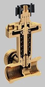
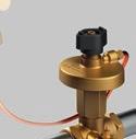
8 2. Introduction 2.3 Design DN The Nexus Valve Passim is installed in the return line. The supply line pressure is channeled above the diaphragm of the Nexus Valve Passim valve through a capillary tube, connected to a partner valve like the Nexus Valve Fluctus, Nexus Valve Vertex or in some instances just to a T-piece in the system. When system pressure increases, it also increases above the internal diaphragm of the Nexus Valve Passim, forcing the spindle downwards and thereby closing the valve gradually. As a result a constant pressure drop is obtained across the circuit controlled by the Nexus Valve Passim Spindle for setting (Allen key) 2 - Connection of capillary tube 3 - Variable ΔP spring 4 - Pressure relieved valve cone 5 - Valve seat 6 - Drain valve and pressure measuring 7 - Rolling diaphragm 8 - Handle for system isolation 5 8
9 DN The Nexus Valve Passim is installed either in the supply or the return line. The supply line pressure is channeled above the diaphragm and the return line pressure under the diaphragm, through capillary tubes. One capillary tube can be connected to a partner valve like the Nexus Valve Fluctus or to a T-piece in the system, and the other capillary tube to the flange of the Nexus Valve Passim valve. When system pressure increases, it also increases above the internal diaphragm of the Nexus Valve Passim, forcing the cone downwards and thereby closing the valve gradually. The result is a constant pressure drop obtained across the circuit controlled by the Nexus Valve Passim. Without the actuator the valve is held in an open position by means of a spring. With force applied on the spindle, the valve will close Union nut for valve 2 - Venting 3 - Nipple for capillary tube 4 - Diaphragm housing 5 - Diaphragm 6 - Regulating knob 7 - Capillary tube 8 - Valve housing 9 - Valve cone 10 - Locking ring 11 - Nut 12 - Stud bolt 13 - Gasket 14 - Gasket for actuator 15 - Disc 16 - Spring 17 - Valve seat 9

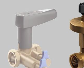
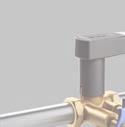
10 2. Introduction 2.4 Pressure balancing DN The Nexus Valve Passim is provided with a selection of actuators for different pressure ranges. Depending on the actuator type the Nexus Valve Passim is factory pre-set at: 10 - actuator 5-25 for Nexus Valve Passim DN actuator for Nexus Valve Passim DN actuator for Nexus Valve Passim DN actuator for Nexus Valve Passim DN actuator for Nexus Valve Passim DN 50 An Allen key is used for differential pressure setting of the Nexus Valve Passim. The black handle enables flow isolation. By using an Allen key any setting within the differential pressure range can be provided. The flow is isolated by rotating the black handle. 10

11 DN The Nexus Valve Passim is provided with a selection of actuators for different pressure ranges. Depending on the actuator type the Nexus Valve Passim is factory pre-set at: 50 - actuator for Nexus Valve Passim DN actuator for Nexus Valve Passim DN The Nexus Valve Passim with an integrated regulating knob for differential pressure setting. By rotating the regulating knob any setting within the differential pressure range can be provided. 11


12 2. Introduction 2.5 With partner valve DN The Nexus Valve Passim can be used in combination with the Nexus Valve Vertex with drain, as a partner valve. In this case the capillary tube is connected to the Nexus Valve Vertex valve installed in the supply line. The pre-setting of the differential pressure is set by use of an Allen key in the Nexus Valve Passim valve and the design flow is then set on the Nexus Valve Vertex valve. When the capillary tube is connected to the drain valve on the P/T pont with the greater measured pressure, the Nexus Valve Vertex valve is inside the circuit controlled by the Nexus Valve Passim valve. In this case the pressure loss across the Nexus Valve Vertex valve must be added to the pressure loss in the controlled circuit and needs to be taken into account when setting the Nexus Valve Passim. When the capillary tube is connected to the drain valve on the P/T port with the lower measured pressure, the Nexus Valve Vertex valve is outside the circuit controlled by the Nexus Valve Passim valve. The Nexus Valve Passim combined with the Nexus Valve Vertex as a partner valve. The Nexus Valve Passim valve can also be used in combination with the Nexus Valve Fluctus with drain, as a partner valve. In this case the capillary tube is connected to the Nexus Valve Fluctus installed in the supply line. The pre-setting of the differential pressure is made as mentioned above, while the design flow can be easily and precisely set when measuring the direct flow utilising the unique measuring feature of the Nexus Valve Fluctus. When the Nexus Valve Fluctus is used as a partner valve it is always in the circuit controlled by the Nexus Valve Passim valve. The pressure loss across the Nexus Valve Fluctus must therefore be added to the pressure loss in the controlled circuit and needs to be taken into account when setting the Nexus Valve Passim valve. The Nexus Valve Passim can also be installed in combination with the Nexus Valve Relax with drain to maintain constant differential pressure, service the controlled part of the system and measure the flow. The Nexus Valve Passim combined with the Nexus Valve Fluctus as a partner valve. 12

13 DN Nexus Valve Passim can be used in combination with a Nexus Valve Fluctus with drain, as a partner valve. In this case one capillary tube is connected to the Nexus Valve Fluctus and the other capillary tube to the flange of the Nexus Valve Passim. The pre-setting of the differential pressure is set by use of the regulating knob on the Nexus Valve Passim valve and the design flow is then set on the Nexus Valve Fluctus valve. The Nexus Valve Passim combined with a Nexus Valve Fluctus as a partner valve. When the Nexus Valve Fluctus is used as a partner valve and installed in the supply line, it is within the circuit controlled by the Nexus Valve Passim. In this case the pressure loss across the Nexus Valve Fluctus valve adds to the pressure loss in the controlled circuit and needs to be taken into account when setting the Nexus Valve Passim valve. The Nexus Valve Passim DN can be installed in the return line. Pressure loss across the Nexus Valve Fluctus (partner valve) is added to the pressure loss in the controlled circuit. When the Nexus Valve Fluctus is used as a partner valve and installed in the return line, it is outside the circuit controlled by the Nexus Valve Passim. Consequently its pressure loss is not taken into account when setting the Nexus Valve Passim. The Nexus Valve Passim DN can be installed in the supply line. Pressure loss across the Nexus Valve Fluctus (partner valve) is not added to the pressure loss in the controlled circuit. 13
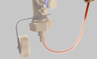
14 2. Introduction 2.6 Mounting Nexus Valve Passim DN15-50 The Nexus Valve Passim valve must always be installed in the return line. No straight piping is required before and after the Nexus Valve Passim. It can be installed directly on bends and flexible hoses, etc. System flushing is to be done before the capillary tube is mounted. The capillary tube is connected onto the Nexus Valve partner valve (or a T-piece) on the supply side. It has to be flushed to ensure that there is no air left. The capillary tube is then mounted onto the Nexus Valve Passim and thus the differential pressure controller is active. The setting of the differential pressure is done by using an Allen key and counting the number of complete turns. The turns are to be performed clockwise, from the first (pre-set) position of: 5.0 for Nexus Valve Passim 5-25, 20 for Nexus Valve Passim for Nexus Valve Passim for Nexus Valve Passim for Nexus Valve Passim The setting tables indicate how many turns of the (4 mm) Allen key are required to achieve the desired Nexus Valve Passim setting. No more turns than stated in the tables must be performed counting from the first position. When using a flowmeter the differential pressure across the riser or zone can be determined. After connecting the flowmeter to the high pressure port on the Nexus Valve Fluctus (or the Nexus Valve Vertex) and to the drain valve of the Nexus Valve Passim, the manometer will display the pressure drop across the riser and the partner valve. When a Nexus Valve Fluctus is used as a partner valve, its pressure drop is always included in the circuit controlled by the Nexus Valve Passim valve. When using a Nexus Valve Vertex as a partner valve, it is important to check if the pressure drop across the valve is included in the circuit controlled by the Nexus Valve Passim valve or not (this depends into which of the two Nexus Valve Vertex measuring points the flowmeter needle is inserted). When the system is pressure tested, the capillary tube must be connected and all valves in the circuit after the Nexus Valve Passim valve opened. This is required to secure the same static pressure on both sides of the diaphragm in order to avoid damaging the differential pressure controller. Maximum test pressure is 25 bar. Isolation of the system flow by means of the Nexus Valve Passim is done by turning the black handle clockwise until the valve is fully closed. To avoid damaging the differential pressure controller during isolation the pressure drop across the valve should never exceed 250. An alternative is to dismount the capillary tube on one side before isolating the valve to protect the differential pressure controller. When valves are shut off, the secondary side of the system can be drained through the 3/4 externally threaded drain valve on the Nexus Valve Passim. The end cap needs to be removed, hose attached and the ball valve opened to enable draining. 14
15 Nexus Valve Passim DN65-80 An arrow on the Nexus Valve valve housing indicates the flow direction to be respected. The Nexus Valve Passim can be installed in any position in the return or in the supply line. No straight piping is required before and after the Nexus Valve Passim. It can be installed directly on bends and flexible hoses, etc. System flushing and pressure testing is to be done before the actuator and the capillary tubes are mounted. The Nexus Valve Passim is normally open when the actuator is not mounted. Maximum system pressure is 16 bar. After the installation of the actuator and the capillary tubes, the diaphragm chamber has to be vented by bleeding through the vent plugs. The setting of the differential pressure is done by turning the regulating knob. The edge of the knob indicates the required differential pressure on the actuator scale. When using a flowmeter the differential pressure across the riser or zone can be determined. After connecting the flowmeter to the high pressure port on the partner valve (Nexus Valve Fluctus) and to the, provided as an accessory, drain valve installed in a T-piece, the flowmeter will display the pressure drop in the controlled circuit. The Nexus Valve Passim valve does not incorporate a shut off function. It is recommended to install isolation valves to be able to service the controlled circuit. 15
16 2. Introduction 2.7 Operation Depending on the application, the Nexus Valve Passim can either be used as a zone valve placed in risers or branches controlling a constant pressure difference across multiple terminal units, or as a terminal unit valve ensuring the required pressure drop across each terminal unit at all loads. Radiator heating system with presettable thermostatic radiator valves. The Nexus Valve Passim provides constant differential pressure across a motorized valve on a terminal unit. When the Nexus Valve Passim valve is installed in combination with Nexus Valve Fluctus or Nexus Valve Vertex, the valves can be used as both a constant pressure regulator and as a maximum flow limiter. This ensures each zone or terminal unit the required pressure drop and that the designed flow will never be exceeded. Radiator heating system with non-presettable thermostatic radiator valves. Such a solution is widely used in radiator heating systems with non-presettable thermostatic radiator valves. 16
17 Nexus Valve Passim along with Nexus Valve Fluctus can be used to limit maximum flow in long branches with several terminal units. The flow distribution among the terminal units is ensured by the proper commissioning of static balancing valves and the operation of motorized valves. System with terminal units controlled by a Nexus Valve Passim and balanced by a Nexus Valve Fluctus. As Nexus Valve Passim ensures the required differential pressure for a circuit under all loads, it is possible to do project handovers in stages due to zone balancing saving both time and money spent on re-commissioning. In practice parts of a building can be taken into use gradually as it is completed ensuring a cost effective handover of the entire project. Partial close-downs can also be done easily without influencing other parts of the system. The Nexus Valve Passim will ensure no overflows and thereby no unnecessary energy consumption, and it will eliminate noise problems, providing a perfectly controlled system. 17
18 3. Applications DN Application 1 - Heating system with pre-settable thermostatic radiator valves Differential pressure across the circuits is stabilised by using Nexus Valve Passim valves. In systems with pre-settable thermostatic radiator valves (TRV), the stabilised differential pressure allows optimum conditions to control the room temperature. By pre-setting the TRV valves, flow is limited and overflow situations are avoided. Noise problems are at the same time also eliminated when using Nexus Valve Passim valves. Application 2 - Heating system with non-presettable thermostatic radiator valves Differential pressure across the circuits is stabilised using Nexus Valve Passim valves. Some systems are equipped with non-presettable thermostatic radiator valves (TRV). Such installations are hard to regulate properly, and significant overflow situations can occur. The Nexus Valve Passim will stabilise the differential pressure across a circuit and provide proper conditions to control the room temperature. When installed with a Nexus Valve Fluctus or a Nexus Valve Vertex as partner valve, the maximum flow can be limited to design flow rate. Overflow situations in the circuit are thereby avoided. This will not provide the correct distribution of flow among the radiators, but it will improve the system performance substantially. Noise nuisances are at the same time also eliminated when using Nexus Valve Passim valves. 18
19 Application 3A - Central heating system with Nexus Valve Passim and Nexus Valve Vertex The Nexus Valve Vertex valve and the Nexus Valve Passim differential pressure control valve can be connected in a way so that the Nexus Valve Vertex valve is inside the circuit controlled by the Nexus Valve Passim valve. This is done when the capillary tube from the Nexus Valve Passim valve is connected to the drain valve at the P/T port of the Nexus Valve Vertex valve with the higher measured pressure. This application is common for heating systems with non-presettable thermostatic radiator valves. In this case the pressure loss across the Nexus Valve Vertex valve needs to be taken into account when setting the Nexus Valve Passim differential pressure control valve. The flow obtained across the Nexus Valve Vertex valve is kept constant due to the constant differential pressure obtained (as long as there is no load change required from the terminal units). 19
20 3. Applications Application 3B - Central heating system with Nexus Valve Passim and Nexus Valve Vertex The Nexus Valve Vertex valve and the Nexus Valve Passim differential pressure control valve can be connected in a way so that the Nexus Valve Vertex valve is outside the circuit controlled by the Nexus Valve Passim valve. This is done when the capillary tube from the Nexus Valve Passim valve is connected to the drain valve at the P/T plug of the Nexus Valve Vertex valve with the lower measured pressure. This application is common for heating systems with pre-settable thermostatic radiator valves. The Nexus Valve Vertex valve can in this application be used as a measuring valve to check if the pre-setting made on the thermostatic radiator valves is correct and if the designed flow is achieved. The Nexus Valve Vertex valve is in this application typically fully open or in a position providing just enough pressure loss required for flow measurement. In this way the pressure loss in the system is kept low. 20
21 Application 4 - Central heating system with the Nexus Valve Passim and the Nexus Valve Relax The Nexus Valve Relax shut-off valve can be used as a partner valve to the Nexus Valve Passim. This combination is suitable for systems with presettable thermostatic radiator valves. The individual flow is set on the thermostatic radiator valve, whereas the flow for the riser can be verified on the Nexus Valve Relax provided that the pressure loss across its measuring points is at least 3.0. The Nexus Valve Relax can be inside or outside the controlled by the Nexus Valve Passim part of the system. Application 5 - Heating system with differential pressure control valves on risers and manual balancing valves on sub-circuits A Nexus Valve Passim on each riser provides a stable differential pressure from the main pipe to the risers and to the sub-circuits. A Nexus Valve Fluctus or a Nexus Valve Vertex on each sub-circuit prevents overflow situations. The differential pressure limitation function of the Nexus Valve Passim valve will furthermore prevent noise problems in the system. 21
22 3. Applications Application 6 - Cooling system with differential pressure control valves on branches and manual balancing valves on terminal units In a system with a high concentration of small terminal units, the differential pressure can be stabilised across a group of terminal units using the Nexus Valve Passim. Nexus Valve Fluctus or Nexus Valve Vertex on each terminal unit limit at the same time the flow according to design conditions. The differential pressure control of the Nexus Valve Passim valve will furthermore prevent noise problems in the system. Application 7 - Underfloor heating system In a system with several underfloor heating manifolds the differential pressure is stabilized by use of Nexus Valve Passim on each branch. The flow adjustment in one manifold will not affect the flow in the remaining manifolds. Nexus Valve Fluctus or Nexus Valve Vertex will ensure the designed flow in every manifold. As a result of this, system commissioning is easy, allowing time and cost savings, and the design flow is never exceeded. 22
23 Application 8 - Flat station and district heating system Nexus Valve Passim can be installed in systems with flat stations. In this type of application flow fluctuations, due to a significant difference between heat consumption for domestic hot water production and for heating purpose, is a typical problem. By installing Nexus Valve Passim the differential pressure is stabilized in every section of the system. The Nexus Valve Passim ensures that a changed flow in one section of the system does not affect the flow and operation of the remaining part of the system. The same function as above applies to district heating systems. Nexus Valve Passim installed in district heating substations will provide stable working conditions for motorized valves on heat exchangers. As a result motorized valves operate only in reference to the changing heat load and not to compensate for fluctuating pressure in the district heating system. 23
24 3. Applications DN The Nexus Valve Passim DN 65 and DN 80 can be used in applications 1-8 as well as in the following ones: Application 9 - Precise temperature control in air handling units When temperatures have to be kept within close limits like in ventilating plants, control may be difficult if the differential pressure in the system is not constant. This may be overcome by installing a Nexus Valve Passim which stabilizes the differential pressure across the motorized valve. As a result the motorized valve reacts only on temperature signals and not on pressure fluctuations. Application 10 - Precise temperature control in domestic water and central heating systems The Nexus Valve Passim valve will in a hot water tank circuit (heat exchanger) or in a central heating system maintain a constant differential pressure across the motorized valve. By providing a stable working condition the motorized valve reacts only on the temperature signal and does not have to compensate for pressure fluctuations. Application 11 - Pressure relief by pump or supply and return line by-pass The Nexus Valve Passim can be used in by-pass around pumps or across the supply and return lines of a circuit. This prevents the pump from working against a dead head when all the subcircuits are closed down. Note: For this application the Nexus Valve Passim with reverse acting valve needs to be ordered. The valve is provided on request only! The Nexus Valve Passim can be installed in the return or the supply line. Installation in the return line is preferable where there is a risk of air in the system, and in high buildings where the pressure in the return pipe does not considerably exceed the static pressure. For low buildings (and high pressures) it is preferable to install the Nexus Valve Passim in the supply line to reduce the pressure in terminal units. 24
25 4. Product data sheet 4.1 Product finder Nexus Valve Passim DN Nexus Valve Passim DN 50 DN 40 DN 32 DN 25 DN 20 DN 15 Flow rate l/s Nexus Valve Vertex partner valve to Nexus Valve Passim DN 50 DN 40 DN 32 DN 25 DN 20 DN 15 Flow rate l/s Nexus Valve Fluctus partner valve to Nexus Valve Passim DN 50 H DN 40 H DN 25 H & DN 32 H DN 20 H & DN 25 S DN 15 H DN 20 S DN 15 S & DN 20 L DN 15 L DN 15 UL Flow rate l/s
26 4. Product data sheet Nexus Valve Passim DN Nexus Valve Passim DN 80 DN Flow rate 60 l/s Nexus Valve Fluctus partner valve to Nexus Valve Passim DN 80 DN 65 Flow rate l/s
27 Flow range Dimension Differential pressure setting range l/s Factory setting [] DN , DN DN DN DN DN DN DN
28 4. Product data sheet 4.2 Nexus Valve Passim DN 15-50, DN Passim DN female/female with drain Dimensions Specifications Max. temperature 120 C (135 C temporarily) Min. temperature -20 C Max. differential pressure 250 Max. pressure 25 bar Differential pressure setting range 5-25, Accuracy +/-25% Marking on valve DN, PN, flow arrow, DR, Kvs Differential pressure setting range Connection Female thread ISO 7/1 parallel Valve housing, seat, cone and internal mechanical parts DR Brass CW602N Spring Stainless steel Sealings and diaphragm EPDM Isolation knob PPS DN A (mm) B (mm) C (mm) (diameter) D (mm) DN ,5 DN ,5 DN DN DN DN DN DN Note! Information on press adaptors and other is provided in the chapter Accessories. 28
29 Valve Article Dimension Nom. Inch DN 15 Kvs m 3 /h N DN 15 ½ ΔP Setting Range [] N DN 15 ½ N DN 15 ½ DN 20 N DN 20 ¾ N DN 20 ¾ N DN 20 ¾ DN 25 N DN N DN N DN DN 32 N DN 32 1¼ N DN 32 1¼ N DN 32 1¼
30 4. Product data sheet Passim DN 40 female/female with drain Passim Dimensions Specifications Max. temperature Min. temperature Max. differential pressure Max. pressure Differential pressure setting range Accuracy +/-25% Marking on valve 120 C (135 C temporarily) -20 C bar 5-25, 20-40, DN, PN, flow arrow, DR, Kvs Differential pressure setting range Connection Female thread ISO 7/1 parallel Valve housing, seat, cone and internal mechanical parts Spring Sealings and diaphragm Isolation knob Top and bottom plates DR Brass CW602N Stainless steel EPDM PPS EN-GJL-250 (GG25) DN A (mm) B (mm) C (mm) (diameter) D (mm) DN 40 99, DN 40 99, DN 40 99, Note! Information on press adaptors and other is provided in the chapter Accessories. 30
31 Valve Article Dimension Nom. Inch DN 40 Kvs m 3 /h N DN 40 1½ ΔP Setting Range [] DN 40 N DN 40 1½ DN 40 N DN 40 1½
32 4. Product data sheet Passim DN 50 female/female with drain Dimensions Specifications Max. temperature Min. temperature Max. differential pressure Max. pressure Differential pressure setting range Accuracy +/-25% Marking on valve 120 C (135 C temporarily) -20 C bar 5-25, 20-40, 35-75, DN, PN, flow arrow, DR, Kvs Differential pressure setting range Connection Female thread ISO 7/1 Valve housing Seat, cone and internal mechanical parts Spring Sealings and diaphragm Isolation knob Top and bottom plates parallel EN-GJL-250 (GG25) DR Brass CW602N Stainless steel EPDM PPS EN-GJL-250 (GG25) DN A (mm) B (mm) C (mm) (diameter) D (mm) DN , ,5 DN ,5 DN , ,5 DN ,5 Note! Information on press adaptors and other is provided in the chapter Accessories. 32
33 Valve Article Dimension Nom. Inch DN 50 Kvs m 3 /h N DN ΔP Setting Range [] DN 50 N DN DN 50 N DN DN 50 N DN
34 4. Product data sheet Passim DN female/female without drain Dimensions Specifications Max. temperature 120 C (135 C temporarily) Min. temperature -20 C Max. differential pressure 250 Max. pressure 25 bar Differential pressure setting range 5-25, Accuracy +/-25% Marking on valve DN, PN, flow arrow, DR, Kvs Differential pressure setting range Connection Female thread ISO 7/1 parallel Valve housing, seat, cone and internal mechanical parts DR Brass CW602N Spring Stainless steel Sealings and diaphragm EPDM Isolation knob PPS DN A (mm) B (mm) C (mm) (diameter) DN DN DN DN DN DN DN DN Note! Information on press adaptors and other is provided in the chapter Accessories. 34
35 Valve Article Dimension Nom. Inch DN 15 Kvs m 3 /h N DN 15 ½ ΔP Setting Range [] N DN 15 ½ DN 20 N DN 20 ¾ N DN 20 ¾ DN 25 N DN N DN DN 32 N DN 32 1¼ N DN 32 1¼

36 4. Product data sheet Passim DN 15 male/male without drain Dimensions Specifications Max. temperature 120 C (135 C temporarily) Min. temperature -20 C Max. differential pressure 450 Max. pressure 16 bar Differential pressure setting range 5-25, Accuracy +/-25% Marking on valve DN, PN, flow arrow, DR, Kvs Differential pressure setting range Connection Male thread G 3/4 ISO228 Valve housing, seat, cone and internal mechanical parts DR Brass CW602N Spring Stainless steel Sealings and diaphragm EPDM Isolation knob PPS DN A (mm) B (mm) C (mm) (diameter) DN ,9 62 DN ,9 62 Note! Information on press adaptors and other is provided in the chapter Accessories. Valve Article Dimension Nom. Inch DN 15 Kvs m 3 /h N DN 15 ¾ ΔP Setting Range [] N DN 15 ¾
37 4.2.6 Passim DN flange/flange Dimensions Specifications Max. temperature Min. temperature Max. differential pressure Max. pressure Differential pressure setting range Leakage range Marking on valve 120 C 120 C (150 C only if the actuator is installed below the valve) -20 C bar 20-80, Less than 0.05% of the full flow (according to VDI/VDE 2174) DN, PN, flow arrow, Kvs, differential pressure setting range, material Flange EN PN16 Cast iron EN-GJS Stainless steel Stainless steel Connection Valve housing Seat, cone and spindle Spring Nuts and bolts 24 CrMo 5/A4 Sealing and membrane EPDM DN A (mm) B (mm) C (mm) D (mm) E (mm) (diameter) DN DN Note! Information on press adaptors and other is provided in the chapter Accessories. Valve Article Dimension Nom. Inch DN 65 Kvs m 3 /h N DN 65 2½ ΔP Setting Range [] N DN 65 2½ DN 80 N DN N DN
38 4. Product data sheet 4.3 Flow diagrams The graphs are used to determine the total pressure loss across the Nexus Valve Passim at the required flow. DN 15 - female/female and male/male bar Pressure drop across valve - ΔPpassim Flow l/s 38
39 DN 20 - female/female bar Pressure drop across valve - ΔPpassim Flow l/s 39
40 4. Product data sheet DN 25 - female/female bar Pressure drop across valve - ΔPpassim Flow l/s 40
41 DN 32 - female/female bar Pressure drop across valve - ΔPpassim Flow l/s 41
42 4. Product data sheet DN 40 - female/female bar Pressure drop across valve - ΔPpassim Flow l/s 42
43 DN 50 - female/female bar Pressure drop across valve - ΔPpassim Flow l/s 43
44 4. Product data sheet DN 65 - flange/flange bar Pressure drop across valve - ΔPpassim Flow l/s 44
45 DN 80 - flange/flange bar Pressure drop across valve - ΔPpassim Flow l/s 45
46 4. Product data sheet 4.4 Valve sizing The available flow ranges in reference to the required differential pressure settings on the Nexus Valve Passim are specified in the tables. DN 15 - female/female Setting Min. flow Max. flow Setting Min. flow Max. flow Setting Min. flow Max. flow The Nexus Valve Passim can be combined with the Nexus Valve Vertex or the Nexus Valve Fluctus to provide constant differential pressure in the controlled part of the system as well as to to ensure the option of limiting the maximum flow. For more details the application examples must be consulted. Partner valve Flow range Dimension Description l/s DN 15 Nexus Valve Vertex with drain. Flow diagram can be found in chapter DN 15UL DN 15L DN 15S DN 15H Nexus Valve Fluctus with drain. Flow diagrams can be found in chapter DN 15 Nexus Valve Relax with drain chapter
47 DN 15 - male/male Setting Min. flow Max. flow Setting Min. flow Max. flow 15* * * * * The nominal differential pressure setting range is 20-40, however is also achievable. The Nexus Valve Passim can be combined with the Nexus Valve Vertex or the Nexus Valve Fluctus to provide constant differential pressure in the controlled part of the system as well as to to ensure the option of limiting the maximum flow. For more details the application examples must be consulted. Partner valve Flow range Dimension Description l/s DN 15 Nexus Valve Vertex with drain. Flow diagram can be found in chapter DN 15UL DN 15L DN 15S DN 15H Nexus Valve Fluctus with drain. Flow diagrams can be found in chapter DN 15 Nexus Valve Relax with drain chapter
48 4. Product data sheet DN 20 - female/female Setting Min. flow Max. flow Setting Min. flow Max. flow Setting Min. flow Max. flow The Nexus Valve Passim can be combined with the Nexus Valve Vertex or the Nexus Valve Fluctus to provide constant differential pressure in the controlled part of the system as well as to to ensure the option of limiting the maximum flow. For more details the application examples must be consulted. Partner valve Flow range Dimension Description l/s DN 20 Nexus Valve Vertex with drain. Flow diagram can be found in chapter DN 20L DN 20S DN 20H Nexus Valve Fluctus with drain. Flow diagrams can be found in chapter DN 20 Nexus Valve Relax with drain chapter
49 DN 25 - female/female Setting Min. flow Max. flow Setting Min. flow Max. flow Setting Min. flow Max. flow The Nexus Valve Passim can be combined with the Nexus Valve Vertex or the Nexus Valve Fluctus to provide constant differential pressure in the controlled part of the system as well as to to ensure the option of limiting the maximum flow. For more details the application examples must be consulted. Partner valve Flow range Dimension Description l/s DN 20 Nexus Valve Vertex with drain. Flow diagram can be found in chapter DN 25S DN 25H Nexus Valve Fluctus with drain. Flow diagrams can be found in chapter DN 20 Nexus Valve Relax with drain chapter
50 4. Product data sheet DN 32 - female/female Setting Min. flow Max. flow Setting Min. flow Max. flow Setting Min. flow Max. flow The Nexus Valve Passim can be combined with the Nexus Valve Vertex or the Nexus Valve Fluctus to provide constant differential pressure in the controlled part of the system as well as to to ensure the option of limiting the maximum flow. For more details the application examples must be consulted. Partner valve Flow range Dimension Description l/s DN 32 Nexus Valve Vertex with drain. Flow diagram can be found in chapter DN 32H Nexus Valve Fluctus with drain. Flow diagrams can be found in chapter DN 32 Nexus Valve Relax with drain chapter
51 DN 40 - female/female Setting Min. flow Max. flow Setting Min. flow Max. flow Setting Min. flow Max. flow The Nexus Valve Passim can be combined with the Nexus Valve Vertex or the Nexus Valve Fluctus to provide constant differential pressure in the controlled part of the system as well as to to ensure the option of limiting the maximum flow. For more details the application examples must be consulted. Partner valve Flow range Dimension Description l/s DN 40 Nexus Valve Vertex with drain. Flow diagram can be found in chapter DN 40H Nexus Valve Fluctus with drain. Flow diagrams can be found in chapter DN 20 Nexus Valve Relax with drain chapter
52 4. Product data sheet DN 50 - female/female Setting Min. flow Max. flow Setting Min. flow Max. flow Setting Min. flow Max. flow Setting Min. flow Max. flow The Nexus Valve Passim can be combined with the Nexus Valve Vertex or the Nexus Valve Fluctus to provide constant differential pressure in the controlled part of the system as well as to to ensure the option of limiting the maximum flow. For more details the application examples must be consulted. Partner valve Flow range Dimension Description l/s DN 50 Nexus Valve Vertex with drain. Flow diagram can be found in chapter DN 50H Nexus Valve Fluctus with drain. Flow diagrams can be found in chapter DN 50 Nexus Valve Relax with drain chapter
53 DN 65 - flange/flange Setting Min. flow Max. flow Setting Min. flow Max. flow Setting Min. flow Max. flow Setting Min. flow Max. flow The Nexus Valve Passim can be combined with the Nexus Valve Vertex or the Nexus Valve Fluctus to provide constant differential pressure in the controlled part of the system as well as to to ensure the option of limiting the maximum flow. For more details the application examples must be consulted. Partner valve Flow range Dimension Description l/s DN 65 Nexus Valve Fluctus with Combi Drain DN 80 Maxi for capillary tube connection (Combi Drain Maxi is provided as an accessory) DN 100 Flow diagram chapter
54 4. Product data sheet DN 80 - flange/flange Setting Min. flow Max. flow Setting Min. flow Max. flow Setting Min. flow Max. flow Setting Min. flow Max. flow The Nexus Valve Passim can be combined with the Nexus Valve Vertex or the Nexus Valve Fluctus to provide constant differential pressure in the controlled part of the system as well as to to ensure the option of limiting the maximum flow. For more details the application examples must be consulted. Partner valve Flow range Dimension Description l/s DN 65 DN 80 Nexus Valve Fluctus with Combi Drain Maxi for capillary tube connection (Combi Drain Maxi is provided as an accessory). Flow diagram chapter

55 4.5 Valve setting The Nexus Valve Passim DN 15 is provided with two pressure setting ranges. The pressure setting is carried out by means of an Allen key. The number of turns needed to obtain the required differential pressure setting is specified in the tables. DN 15 - female/female Differential pressure setting range 5-25 Turns Differential pressure setting range Turns Differential pressure setting range Turns Differential pressure setting range Factory setting Other settingsfactory setting To set the Nexus Valve Passim to any other setting, turn the Allen key counterclockwise till the end point is reached and the spring is completely loosened. From this point turn the Allen key clockwise the number of turns that will give the required ΔP-setting according to the tables above. 4 mm Allen key is used for differential pressure setting. 55
56 4. Product data sheet The Nexus Valve Passim DN 15 is provided with two pressure setting ranges. The pressure setting is carried out by means of an Allen key. The number of turns needed to obtain the required differential pressure setting is specified in the tables. DN 15 - male/male Differential pressure setting range 5-25 Turns Differential pressure setting range Turns 0* 15 1* 16 2* 18 3* *The nominal differential pressure setting range is 20-40, however is also achievable. Differential pressure setting range Factory setting Other settingsfactory setting To set the Nexus Valve Passim to any other setting, turn the Allen key counterclockwise till the end point is reached and the spring is completely loosened. From this point turn the Allen key clockwise the number of turns that will give the required ΔP-setting according to the tables above. 4 mm Allen key is used for differential pressure setting. 56
57 Nexus Valve Passim DN 20 is provided with two pressure setting ranges. The pressure setting is carried out by means of an Allen key. The number of turns needed to obtain the required differential pressure setting is specified in the tables. DN 20 - female/female Differential pressure setting range 5-25 Turns Differential pressure setting range Turns Differential pressure setting range Turns Differential pressure setting range Factory setting Other settingsfactory setting To set the Nexus Valve Passim to any other setting, turn the Allen key counterclockwise till the end point is reached and the spring is completely loosened. From this point turn the Allen key clockwise the number of turns that will give the required ΔP-setting according to the tables above. 4 mm Allen key is used for differential pressure setting. 57
58 4. Product data sheet Nexus Valve Passim DN 25 is provided with two pressure setting ranges. The pressure setting is carried out by means of an Allen key. The number of turns needed to obtain the required differential pressure setting is specified in the tables. DN 25 - female/female Differential pressure setting range 5-25 Turns Differential pressure setting range Turns Differential pressure setting range Turns Differential pressure setting range Factory setting Other settingsfactory setting To set the Nexus Valve Passim to any other setting, turn the Allen key counterclockwise till the end point is reached and the spring is completely loosened. From this point turn the Allen key clockwise the number of turns that will give the required ΔP-setting according to the tables above. 4 mm Allen key is used for differential pressure setting. 58
59 Nexus Valve Passim DN 32 is provided with two pressure setting ranges. The pressure setting is carried out by means of an Allen key. The number of turns needed to obtain the required differential pressure setting is specified in the tables. DN 32 - female/female Differential pressure setting range 5-25 Turns Differential pressure setting range Turns Differential pressure setting range Turns Differential pressure setting range Factory setting Other settingsfactory setting To set the Nexus Valve Passim to any other setting, turn the Allen key counterclockwise till the end point is reached and the spring is completely loosened. From this point turn the Allen key clockwise the number of turns that will give the required ΔP-setting according to the tables above. 4 mm Allen key is used for differential pressure setting. 59
60 4. Product data sheet Nexus Valve Passim DN 40 is provided with three pressure setting ranges. The pressure setting is carried out by means of an Allen key. The number of turns needed to obtain the required differential pressure setting is specified in the tables. DN 40 - female/female Differential pressure setting range 5-25 Turns Differential pressure setting range Turns Differential pressure setting range Turns Differential pressure setting range Factory setting Other settingsfactory setting To set the Nexus Valve Passim to any other setting, turn the Allen key counterclockwise till the end point is reached and the spring is completely loosened. From this point turn the Allen key clockwise the number of turns that will give the required ΔP-setting according to the tables above. 4 mm Allen key is used for differential pressure setting. 60
61 Nexus Valve Passim DN 50 is provided with four pressure setting ranges. The pressure setting is carried out by means of an Allen key. The number of turns needed to obtain the required differential pressure setting is specified in the tables. DN 50 - female/female Differential pressure setting range 5-25 Turns Differential pressure setting range Turns Differential pressure setting range Turns Differential pressure setting range Turns Differential pressure setting range Factory setting Other settingsfactory setting To set the Nexus Valve Passim to any other setting, turn the Allen key counterclockwise till the end point is reached and the spring is completely loosened. From this point turn the Allen key clockwise the number of turns that will give the required ΔP-setting according to the tables above. 4 mm Allen key is used for differential pressure setting. 61
62 4. Product data sheet DN 65 - flange/flange The Nexus Valve Passim DN 65 is provided with two differential pressure setting ranges. The differential pressure setting is carried out by means of a regulating knob. The setting scale is clearly marked on the actuator. Any differential pressure setting can be verified by checking the position of the regulating knob edge in reference to the scale. Differential pressure setting range Factory setting Other settingsfactory setting Differential pressure setting To set the Nexus Valve Passim to any other setting, turn the regulating knob so that the edge of the knob points to the required differential pressure on the actuator scale. The Nexus Valve Passim DN 65 is provided with two capillary tubes so the valve can be installed in the supply or the return line. The valve does not offer the shut off function, thus it is recommended to install isolation valves in the system with Nexus Valve Passim DN
63 DN 80 - flange/flange The Nexus Valve Passim DN 80 is provided with two differential pressure setting ranges. The differential pressure setting is carried out by means of a regulating knob. The setting scale is clearly marked on the actuator. Any differential pressure setting can be verified by checking the position of the regulating knob edge in reference to the scale. Differential pressure setting range Factory setting Other settingsfactory setting Differential pressure setting To set the Nexus Valve Passim to any other setting, turn the regulating knob so that the edge of the knob points to the required differential pressure on the actuator scale. The Nexus Valve Passim DN 80 is provided with two capillary tubes so the valve can be installed in the supply or the return line. The valve does not offer the shut off function, thus it is recommended to install service isolation valves in the system with Nexus Valve Passim DN


64 5. Accessoires There is a wide range of accessories and spare parts available for Nexus Valve Passim valves. These comprise: insulation jackets, press adaptors, high capacity drain valve and other Accessories Article Dimension Description N DN 15 Nexus Valve Vertex with drain for capillary tube connection. N DN 20 N DN 25 N DN 32 N DN 40 N DN 50 N DN 15U Nexus Valve Fluctus with drain for capillary tube connection. N DN 15L N DN 15S N DN 15H N DN 20L N DN 20S N DN 20H N DN 25S N DN 25H N DN 32H N DN 40H N DN 50H N DN 15 N DN 20 N DN 25 N DN 32 N DN 40 N DN 50 64


65 Accessories Article Dimension Description N mm ½ Pre-sealed press adaptors (2 pcs) for valve DN 15-50, max. 16 bar N mm ½ N mm x ¾" N mm x ¾" N mm x ¾ N mm x 1 N mm x 1¼ N mm x 1½ N mm x 2" N ¾ Cap with test point installed on the drain or T-piece valve of the Nexus Valve Passim for measuring the differential pressure during commissioning N N DN 65 DN 80 Nexus Valve Fluctus, when used as a partner valve, must be provided with Combi Drain Maxi for capillary tube connection. The drain is provided as an N DN 100 accessory and must be ordered separately. N R ¼ Combi Drain Maxi drain with measuring point for Nexus Valve Fluctus DN The capillary tube from the Nexus Valve Passim can be connected to the ¼ coupling delivered along with the Combi Drain Maxi and installed on the drain N m, Ø 4 mm Capillary tube with connector for Nexus Valve Passim DN N m, Ø 4 mm Capillary tube with connector for Nexus Valve Passim DN
66 6. Sizing examples 6.1 DN System with Nexus Valve Passim and Nexus Valve Fluctus A Nexus Valve Passim and a Nexus Valve Fluctus partner valve is in this example sized to the following conditions: The designed branch flow controlled by the Nexus Valve Passim is 0.4 l/s (1440 ). The available system differential pressure (ΔPa) is 50. The required branch differential pressure (ΔPc) is 20. ΔP a ΔP BV ΔP c Δ Pa - available differential pressure in the system Δ Pc - differential pressure required for the branch Δ Pbv - pressure loss across Nexus Valve Fluctus Δ PPassim - pressure loss across Nexus Valve Passim ΔP a = ΔP BV + ΔP c + ΔP PASSIM ΔP PASSIM The pressure loss across the Nexus Valve Passim valve is found in the product data sheet graphs in chapter bar Pressure drop across valve - ΔPPassim Graph for Nexus Valve Passim DN Flow l/s Three valves (in fully open position) can provide the required flow of 0.4 l/s: Nexus Valve Passim DN 20 ΔPPassim = 33 Nexus Valve Passim DN 25 ΔPPassim = 13 Nexus Valve Passim DN 32 ΔPPassim = 5 66
67 The suitable Nexus Valve Fluctus partner valve is selected from the flow diagrams in chapter 3.1. It is recommended to use valves in fully open position at the required flow to reduce the pump head and save energy: Nexus Valve Fluctus DN 20H ΔPbv = 6.5 (see chapter ) Nexus Valve Fluctus DN 25S ΔPbv = 3.5 (see chapter ) Nexus Valve Fluctus DN 32H ΔPbv = 1.2 (see chapter ) bar Pressure drop across valve Position Flow l/s Graph for Nexus Valve Fluctus DN 25S. The minimum required ΔPa for each valve set is calculated as follows: ΔPa = ΔPbv + ΔPc + ΔPPassim DN 20 Min. ΔPa = = 59.5 DN 25 Min. ΔPa = = 36.5 DN 32 Min. ΔPa = = 26.2 To ensure the best functionality of the Nexus Valve Passim, the smallest possible valve is selected. However, the DN 20 solution requires minimum ΔPa of 59.5 to operate properly, and the system provides a ΔPa of only 50. Therefore the DN 25 valve is selected with an actuator. The correct ΔP setting on the Nexus Valve Passim is: ΔPbv + ΔPc = = 23.5 To make sure the Nexus Valve Passim valve will keep the required differential pressure (ΔPc + ΔPbv) [] constant within the circuit at flow 0.4 l/s, the product data sheets must be consulted. Setting Min. flow Max. flow Extract from the Nexus Valve Passim DN 25 sizing table At a setting of 24, the available flow range is and the design flow of 1440 is within the range. Articles used: Nexus Valve Passim DN 25, 20-40, Article No. N Nexus Valve Fluctus with drain DN 25 S, Article No. N
68 6. Sizing examples System with Nexus Valve Passim and Nexus Valve Vertex A Nexus Valve Passim and a Nexus Valve Vertex are in this example sized to the following conditions: The designed branch flow controlled by the Nexus Valve Passim valve is 0.15 l/s (540 ). The available system differential pressure (ΔPa) is 35. The required branch differential pressure (ΔPc) is 15. The system has radiators with pre-settable thermostatic radiator valves installed. The flow can therefore be adjusted on the thermostatic radiator valves and the Nexus Valve Vertex can be installed outside the circuit controlled by the Nexus Valve Passim. Pressure loss across the Nexus Valve Vertex is not taken into account when setting the Nexus Valve Passim. The Nexus Valve Vertex must be in a fully open position. ΔP a ΔP BV ΔP PASSIM ΔP c ΔP a = ΔP BV + ΔP c + ΔP PASSIM Δ Pa - available differential pressure in the system Δ Pc - differential pressure required for the branch Δ Pbv - pressure loss across Nexus Valve Vertex Δ PPassim - pressure loss across Nexus Valve Passim The pressure loss across the Nexus Valve Passim valve is found in the product data sheet graphs in chapter bar Pressure drop across valve - ΔPpassim Graph for Nexus Valve Passim DN Flow l/s Three valves (in fully open position) can provide required flow of 0.15 l/s: Nexus Valve Passim DN 15 ΔPPassim = 11.5 Nexus Valve Passim DN 20 ΔPPassim = 4.5 Nexus Valve Passim DN 25 ΔPPassim =
69 The suitable Nexus Valve Vertex partner valve is selected based on the flow diagrams in chapter 3.2. It is recommended to use valves in fully open position at the required flow to reduce the pump head and save energy: Nexus Valve Vertex DN 15 ΔPbv = 10.0 (see chapter ) Nexus Valve Vertex DN 20 ΔPbv = 1.5 (see chapter ) Nexus Valve Vertex DN 25 ΔPbv = 1.0 (see chapter ) bar Pressure drop across valve Position Graph for Nexus Valve Vertex DN Flow l/s The minimum required ΔPa for each valve set is calculated as follows: ΔPa = ΔPbv + ΔPc + ΔPPassim DN 15 Min. ΔPa = = 36.5 DN 20 Min. ΔPa = = 21.0 DN 25 Min. ΔPa = = 17.5 To ensure the best functionality of the Nexus Valve Passim, the smallest possible valve is selected. However, the DN 15 solution requires minimum ΔPa of 36.5 to operate properly, and the system provides a ΔPa of only 35. Therefore the DN 20 valve is selected with an 5-25 actuator. The correct ΔP setting on the Nexus Valve Passim valve is: ΔPc = 15.0 To make sure the Nexus Valve Passim valve will keep the required differential pressure ΔPc [] constant within the circuit at flow 0.15 l/s, the product data sheets must be consulted. Setting Min. flow Max. flow Extract from the Nexus Valve Passim DN 20 sizing table At a setting of 15, the available flow range is and the design flow of 540 is within the range. Articles used: Nexus Valve Passim DN 20, 5-25, Article No. N Nexus Valve Vertex with drain DN 20 Article No. N
70 6. Sizing examples 6.2 DN System with Nexus Valve Passim and Nexus Valve Fluctus A Nexus Valve Passim and a Nexus Valve Fluctus partner valve are sized to the following conditions: The designed branch flow controlled by the Nexus Valve Passim is 5.0 l/s (18000 ). The available system differential pressure ΔPa) is 60. The required branch differential pressure controlled by the Nexus Valve Passim (ΔPc) is 40. ΔPa ΔPpassim ΔPbv ΔPc ΔPa = ΔPbv + ΔPc + ΔPpassim Δ Pa - available differential pressure in the system Δ Pc - differential pressure required for the circuit Δ Pbv - pressure loss across partner valve (Nexus Valve Fluctus) Δ PPassim - pressure loss across the Nexus Valve Passim The pressure loss across the Nexus Valve Passim valve is found in the product data sheet graphs in chapter bar Pressure drop across valve - ΔPpassim Graph for Nexus Valve Passim DN xDN 0xDN 5 x DN 0 x DN Flow l/s Two valves (in fully open position) can provide the required flow of 5.0 l/s: Nexus Valve Passim DN 65 ΔPPassim = 10 Nexus Valve Passim DN 80 ΔPPassim = 5 70
71 The suitable Nexus Valve Fluctus partner valves are selected based on the flow diagrams in chapter 3.1. It is recommended that the valve setting at the required flow is as close to the fully open position as possible. This enables the valve to operate at the required authority, and any valve setting change will result in a high pressure loss for precise flow adjustment: Nexus Valve Fluctus DN 65, ΔPbv = 5.3 valve fully open (see chapter ) Nexus Valve Fluctus DN 80, ΔPbv = 4.0 valve in position 3.5 (see chapter )) bar Pressure drop across valve Position Flow l/s m 3 /h Graph for Nexus Valve Fluctus DN 65. The minimum required ΔPa for each valve set is calculated as follows: ΔPa = ΔPbv + ΔPc + ΔPpassim DN 65 Min. ΔPa = = 55.3 DN 80 Min. ΔPa = = 49.0 To ensure the best functionality of the Nexus Valve Passim, the smallest possible valve is selected. Therefore the DN 65 valve is selected with an actuator The correct ΔP setting on the Nexus Valve Passim valve is: ΔPbv + ΔPc = = 45.3 To make sure the Nexus Valve Passim valve will keep the required differential pressure (ΔPc + ΔPbv) [] constant within the circuit at flow Q [l/s], the product data sheets must be consulted. At the setting of 46, the available flow range is 1570 to and the design flow of is within the range. Setting Min. flow Max. flow Extract of the table for Nexus Valve Passim DN Ordering: Nexus Valve Passim DN 65, Article No.: N , Nexus Valve Fluctus DN 65, Article No.: N , Combi Drain Maxi for capillary tube connection, Article No.: N
72 6. Sizing examples 6.3 General specifications DN Differential pressure control valve DN The Contractor must install differential pressure control valves where indicated in drawings. 2. Function 2.1. The valve must be used to provide constant differential pressure in the controlled circuit Differential pressure setting must be externally adjustable The positioning of the valve with actuator must be possible in all directions (360 around the pipe axis) The valve must have no requirement for straight up- or downstream piping. 3. Valve Body 3.1. The valve body must be made of hot stamped DR brass CW602N CuZn36Pb2As or of cast iron EN-GJL-250 (GG25) The pressure rating must be no less than PN25 (PN16) The valve must comprise differential pressure control, isolation and draining in one single unit A flow arrow must be indicated in the valve body The actuator and drain valve must be positioned perpendicular to each other Pressure testing must be possible in all directions (360 around the pipe axis) after installing a test point cap on the drain valve. 4. Actuator 4.1. The housing of the actuator must be made of DR brass CW602N CuZn36Pb2As or of cast iron EN-GJL-250 (GG25) The actuator must incorporate a handle for valve isolation The actuator must enable differential pressure setting using an Allen key Twenty 360 rotations of an Allen key must ensure the full differential pressure setting range. 72
73 6.4 General specifications DN Differential pressure control valve DN The Contractor must install the differential pressure control valve where indicated in drawings. 2. Function 2.1. The valve must be used to provide constant differential pressure in the controlled circuit Differential pressure setting must be externally adjustable The positioning of the valve with actuator must be possible in all directions (360 around the pipe axis) at a temperature range up to 120 C The valve must have no requirement for straight up- or downstream piping. 3. Valve Body 3.1. The valve body must be made of cast iron EN-GJS The pressure rating must be no less than PN The valve must be installed in the supply or in the return line A flow arrow must be indicated on the valve body. 4. Actuator 4.1. The actuator housing must be made of cast iron The actuator must incorporate a knob for differential pressure setting The differential pressure setting scale must be marked on the actuator The edge of the regulating knob must indicate the differential pressure setting Actuators with different setting ranges must be interchangeable. 73
74 Notes 74
75 Contact Contact data

76 xxx Valid since Subject to technical modifications meibes-group
Versions. Benefits. Balancing DN15-32 DN40 DN50 DN15, DN20, DN25, DN32, DN40, DN50. Dimensions
 Ballorex Delta Description The Ballorex Delta is a differential pressure control valve used in hydronic heating or cooling systems. By ensuring a constant differential pressure across motorized or static
Automatic balancing valves ASV
 Automatic balancing valves ASV ASV-P ASV-PV ASV-PV ASV-PV ASV-I ASV-M 15-40 15-40 50 65-100 15-50 15-50 Description / Application ASV balancing valves are used for dynamic hydronic balance in heating and
Automatic Balancing Valve Pressure difference controller with integrated flow limiter AB-PM DN
 Data sheet Automatic Balancing Valve Pressure difference controller with integrated flow limiter AB-PM DN 40-100 Description AB-PM is ideal for staged installation and commissioning AB-PM is a combined
STAP. Differential pressure controller DN 15-50
 Differential pressure controller 15-50 Pressurisation & Water Quality Balancing & Control Thermostatic Control ENGINEERING ADVANTAGE is a high-performing differential pressure controller that keeps the
STAP. Differential pressure controller DN
 STAP Differential pressure controller DN 65-100 Pressurisation & Water Quality Balancing & Control Thermostatic Control ENGINEERING ADVANTAGE The flanged STAP is a high-performing differential pressure
Automatic balancing valves ASV
 Automatic balancing valves ASV ASV-PV ASV-PV ASV-PV ASV-BD ASV-M DN 15-40 DN 50 DN 65-100 DN 15-50 DN 15-50 Description / Application ASV balancing valves are used for dynamic hydronic balance in heating
Differential pressure controller (PN 16) AHP - return mounting, adjustable setting
 AHP - return mounting, adjustable setting") Data sheet Differential pressure controller (PN 16) AHP - return mounting, adjustable setting Description DN 15-40 DN 50 DN 65-100 AHP is a self-acting differential pressure controller primarily for use
Data sheet Differential pressure controller (PN 16) AHP - return mounting, adjustable setting Description DN 15-40 DN 50 DN 65-100 AHP is a self-acting differential pressure controller primarily for use
Ballorex Dynamic Description. Versions. Benefits. Balancing
 Ballorex Dynamic Description The Ballorex Dynamic valve is a combined pressure independent flow limiter and control valve which maintains a constant flow independently of pressure changes in heating or
Automatic balancing valves
 Automatic balancing valves ASV DN 15-50 (4th gen.) ASV-PV ASV-BD ASV-M DN 15-50 DN 15-50 DN 15-50 Description ASV whiteboard animation ASV valves are automatic balancing valves. Together with Danfoss presetting
STAP. Differential pressure controllers DN , ANSI flanges
 STAP Differential pressure controllers DN 65-100, ANSI flanges IMI TA / Differential pressure controllers / STAP STAP The flanged STAP is a high-performing differential pressure controller that keeps the
Overview of types. T5-R B2/R B2 en v Subject to changes 1 / 4. k vs (Sequence 2)
") Technical data sheet R3015-..-..-B2 / R3020-..-..-B2 Characterised control valves, 6-way, with internal threads Two sequences (cooling/heating) With a rotary actuator 90 Water-side switching or modulating
Technical data sheet R3015-..-..-B2 / R3020-..-..-B2 Characterised control valves, 6-way, with internal threads Two sequences (cooling/heating) With a rotary actuator 90 Water-side switching or modulating
Pressure Independent Control Series
 Document No. 155-522 Pressure Independent Control Series Two-Way Cast Iron Flanged Bodies, ANSI 125 and 250 Description Siemens Pressure Independent Control Valves integrate three functions into a single
2-port seat valves PN25 with externally threaded connections
 4 379 2-port seat valves PN25 with externally threaded connections VVG55.. Valve body bronze CC491K (Rg5) DN 15...25 (½...1 ") kvs 0.25...6.3 m3/h Stroke 5.5 mm Sets of ALG.. with threaded and ALS.. with
STAP. Differential pressure controllers DN , ANSI fl anges
 STAP Differential pressure controllers DN 65-100, ANSI fl anges IMI TA / Differential pressure controllers / STAP STAP The fl anged STAP is a high-performing differential pressure controller that keeps
differential pressure regulating valve - threaded
 140-142 differential pressure regulating valve - threaded Introduction Differential pressure regulating valves (DPRV) maintain the differential pressure across a circuit or sub-branch at a set differential
Pressure independent balancing and control valve AB-QM DN
 Data sheet Pressure independent balancing and control valve AB-QM DN 10-250 The AB-QM valve equipped with an actuator is a control valve with full authority and an automatic balancing function / flow limitation.
Differential pressure controller (PN 25) AVP - return and flow mounting, adjustable setting
 AVP - return and flow mounting, adjustable setting") Differential pressure controller (PN 25) AVP - return and flow mounting, adjustable setting Description AVP(-F) is a self-acting differential pressure controller primarily for use in district heating systems.
Differential pressure controller (PN 25) AVP - return and flow mounting, adjustable setting Description AVP(-F) is a self-acting differential pressure controller primarily for use in district heating systems.
Technote. Frese PV-SIGMA Compact Dynamic Pressure and Flow Regulation. Description. Application. Operation. Features. Benefits.
 Page 1 of 15 Dynamic Pressure and Regulation Description The system is a dynamic valve arrangement designed to regulate flow and differential pressure. Application The system can be installed in both domestic
AVP-F. p setting range (bar) Code No. 003H6200
 Code No. 003H6200") Data sheet Differential pressure controller (PN 16) AVP - return and flow mounting, adjustable setting AVP-F - return mounting, fixed setting Description The controller has a control valve, an actuator
Data sheet Differential pressure controller (PN 16) AVP - return and flow mounting, adjustable setting AVP-F - return mounting, fixed setting Description The controller has a control valve, an actuator
Three-port valves. Special versions with special stem sealing gland for: High temperature hot water C Thermo oils
 4 440 Three-port valves with flange, PN6 VXF4... Three-port valves with flange, PN6 Can be used as mixing or diverting valves Grey cast iron GG-25 DN5...50 mm k vs.9...300 m 3 /h Stroke 20 or 40 mm Can
Differential pressure and flow controller (PN 16) AVPQ - return mounting, adjustable setting
 AVPQ - return mounting, adjustable setting") Data sheet Differential pressure and flow controller (PN 16) AVPQ - return mounting, adjustable setting Description AVPQ is a self-acting differential pressure and flow controller primarily for use in
Data sheet Differential pressure and flow controller (PN 16) AVPQ - return mounting, adjustable setting Description AVPQ is a self-acting differential pressure and flow controller primarily for use in
Differential pressure controller (PN 16) AVPL - return mounting, adjustable setting
 AVPL - return mounting, adjustable setting") Data sheet Differential pressure controller (PN 16) AVPL - return mounting, adjustable setting Description It can be used on primary side of house substations for smaller systems such as one and two-family
Data sheet Differential pressure controller (PN 16) AVPL - return mounting, adjustable setting Description It can be used on primary side of house substations for smaller systems such as one and two-family
2-port and 3-port valves PN 16
 OEM 2-port valves VVP459.10-0.63 to VVP459.25-6.3 3-port valves VXP459.10-0.63 to VXP459.25-6.3 3-port valves with bypass VMP459.10-0.63 to VMP459.20-4 2-port valves VVP459.25-6.3 to VVP459.40-25 3-port
Automatic balancing valves ASV
 Automatic balancing valves ASV ASV-P ASV-PV ASV-PV ASV-PV ASV-BD ASV-I ASV-M 15-40 15-40 50 65-100 15-50 15-50 15-50 Description / Application ASV balancing valves are used for dynamic hydronic balance
Overview of types. Technical data. Safety notes
 Technical data sheet R2..-S.. Open-close ball valves, 2-way, with internal thread For open and closed cold and warm water systems For shut-off functions on the water side and 2-point controls in U and
Upgradable balancing valves USV
 Upgradable balancing valves USV Application / Description USV-I USV-M USV valves are designed for manual hydronic balancing of heating and cooling systems. USV-I (red knob) is used together with USV-M
Technote. Frese PVS - Dynamic Pressure and Flow Regulation Valve. Application. Features. Benefits.
 Page 1 of 15 - Dynamic Pressure and Regulation Valve Application system can be installed in domestic and commercial heating and cooling systems. system is a dynamic valve arrangement designed to regulate
Differential pressure controller (PN 16) AVPL return mounting, adjustable setting
 AVPL return mounting, adjustable setting") Data sheet Differential pressure controller (PN 16) AVPL return mounting, adjustable setting Description It can be used on primary side of house substations for smaller systems such as one and two-family
Data sheet Differential pressure controller (PN 16) AVPL return mounting, adjustable setting Description It can be used on primary side of house substations for smaller systems such as one and two-family
Two-port seat valves
 4 345 Two-port seat valves with flange, PN16 VVF45... Two-port seat valves with flange, PN16 Spheroidal cast iron GGG-40 DN50...150 mm k vs 19...300 m 3 /h Stroke 20 or 40 mm Can be equipped with actuators
TA-FUSION-P. Combined control & balancing valves Pressure independent combined balancing and control valves with independent EQM characteristics
 TA-FUSION-P Combined control & balancing valves Pressure independent combined balancing and control valves with independent EQM characteristics IMI TA / Control valves / TA-FUSION-P TA-FUSION-P These innovative
Type overview. R B2 en-gb subject to changes 1
 Technical data sheet R30..-..-..-B2 Characterised control valve, 6-way, Internal thread Two sequences (cooling/heating) with one 90 rotary actuator Switching or modulating control on the water side of
Overview of types. Technical data
 Technical data sheet R2..xx-S.. Characterised control valves, 2-way, with internal thread For open and closed cold and warm water systems For modulating water-side control of U and heating systems ir bubble
Differential Pressure Control Valve (DPCV)
") Differential Pressure Control Valve (DPCV) PATENTED Technical Data and Installation Instructions Page 1 V2 The modulating valves ART 241 balance and control the differential pressure (DPCV) automatically
Differential Pressure Control Valve (DPCV) PATENTED Technical Data and Installation Instructions Page 1 V2 The modulating valves ART 241 balance and control the differential pressure (DPCV) automatically
Products no longer available
 Technical data sheet R2.. Characterized control valves, 2-way, with internal thread for open and closed cold and warm water systems for modulating control on the water side of air-handling and heating
Two-port valves, male threaded, PN25
 4 379 Two-port valves, male threaded, PN25 VVG55... Two-port valves, externally threaded, PN25 Bronze Rg5 DN15... 25 mm (½"... 1") k vs 0.25... 6.3 m 3 /h Stroke 5.5 mm Suitable for type SQS35... or SQS65...
Rp [ ] Sv min. [ ] C215QP-B 15 1/ C215QP-D 15 1/ C220QP-F 20 3/ [ ]
![Rp [ ] Sv min. [ ] C215QP-B 15 1/ C215QP-D 15 1/ C220QP-F 20 3/ [ ]](/thumbs/75/72185867.jpg "Rp [ ] Sv min. [ ] C215QP-B 15 1/ C215QP-D 15 1/ C220QP-F 20 3/ [ ]") Technical data sheet C2..QP-.. For closed cold and warm water systems For modulating control of airhandling and heating systems on the water side Snap-assembly of the actuator overview DN [ ] Vnom [ l/h]
Technical data sheet C2..QP-.. For closed cold and warm water systems For modulating control of airhandling and heating systems on the water side Snap-assembly of the actuator overview DN [ ] Vnom [ l/h]
Technical data sheet. Type overview. Technical data. Safety notes. T5-R2.. Open-close en v Subject to changes 1 / 3
 Technical data sheet R2.. Open-close ball valves, 2-way, with internal thread for open and closed cold and warm water systems for shut-off functions on the water side and 2-point controls in air-handling
HERZ-Motorised flow controler
 HERZ-Motorised flow controler Control and regulating valve Data sheet 46, Issue 214 Dimensions in mm 4 close dimension 9,35 M DN G H1 H2 H2 + Actuator B1 B2 1 2 M 1 46 11 15 3/4 G 66 59 73 134 49 63 48
3-port seat valves with externally threaded connection, PN 16
 4 463 Acvatix 3-port seat valves with externally threaded connection, PN 16 VXG41.. ronze CuSn5Zn5Pb2 valve body DN 15 50 k vs 1.6 40 m 3 /h Flat sealing connections with external thread G to ISO 228-1
TBV-CM. Combined control & balancing valves for small terminal units For modulating control
 TBV-CM Combined control & balancing valves for small terminal units For modulating control IMI TA / Control valves / TBV-CM TBV-CM Designed for use in terminal units in heating and cooling systems, the
V5001P. Kombi-Auto Differential Pressure Control Valve. Product specification sheet
 V5001P Kombi-Auto Differential Pressure Control Valve Product specification sheet Content Application...1 Special Features...1 Valve Efficiency...1 Technical Data...2 Construction...2 Materials...2 Method
Pressure reduction controller (PN 16, 25, 40)
") Pressure reduction controller (PN 16, 25, 40) AFD / VFG 2( - for water AFD / VFGS 2 - for steam Description The controller has a control valve, an actuator with one control diaphragm and a spring for pressure
Pressure reduction controller (PN 16, 25, 40) AFD / VFG 2( - for water AFD / VFGS 2 - for steam Description The controller has a control valve, an actuator with one control diaphragm and a spring for pressure
Pressure independent control valve (PICV) FLOWMATIC
 FLOWMATIC") Pressure independent control valve (PICV) FLOWMATIC 145 series FM 21654 003 01262/19 GB replaces dp 01262/17 GB Function The pressure independent control valve is a device composed of an automatic flow
Pressure independent control valve (PICV) FLOWMATIC 145 series FM 21654 003 01262/19 GB replaces dp 01262/17 GB Function The pressure independent control valve is a device composed of an automatic flow
Differential pressure controller with flow limitation (PN 16, 25, 40) AFPB / VFQ 2(1) AFPB-F / VFQ 2(1)
 AFPB / VFQ 2(1) AFPB-F / VFQ 2(1)") Data sheet Differential pressure controller with flow limitation (PN 16, 25, 40) AFPB / VFQ 2( AFPB-F / VFQ 2( return mounting, adjustable setting return mounting, fixed setting Description The controller
Data sheet Differential pressure controller with flow limitation (PN 16, 25, 40) AFPB / VFQ 2( AFPB-F / VFQ 2( return mounting, adjustable setting return mounting, fixed setting Description The controller
TA-Modulator. Combined control & balancing valves for small terminal units Pressure independent balancing and control valve for modulating control
 TA-Modulator Combined control & balancing valves for small terminal units Pressure independent balancing and control valve for modulating control IMI TA / Control valves / TA-Modulator TA-Modulator The
TA-COMPACT-P. Combined control & balancing valves for small terminal units Pressure independent balancing and control valve (PIBCV)
") Combined control & balancing valves for small terminal units Pressure independent balancing and control valve (PIBCV) IMI TA / Control valves / The pressure independent balancing and control valve ensures
Combined control & balancing valves for small terminal units Pressure independent balancing and control valve (PIBCV) IMI TA / Control valves / The pressure independent balancing and control valve ensures
TECHNICAL DATA. Q= Cv S
 Page 1 of 13 1. DESCRIPTION The Viking 4 inch Model G-4000 Dry Valve Riser Assembly consists of a small profile, light weight, pilot operated valve that is used to separate the water supply from the dry
TRV-2, TRV-2S. Thermostatic radiator valves With presetting
 TRV-2, TRV-2S Thermostatic radiator valves With presetting IMI EIMEIER / Thermostatic heads and Radiator valves / TRV-2, TRV-2S TRV-2, TRV-2S Thermostatic radiator valve primary for radiators in heating
TECHNICAL DATA. Q = C v P S
 Page 1 of 13 1. DESCRIPTION The Viking 6 Model G-6000 Dry Valve Riser Assembly consists of a small profile, light weight, pilot operated valve that is used to separate the water supply from the dry sprinkler
CAST IRON VALVES FLOAT VALVE
 CAST IRON VALVES FLOAT VALVE NETAFIM CAST IRON VALVES FLOAT VALVE INLINE 25-400MM ANGLE 50-100MM SPECIFICATIONS Manufactured to ISO 9001 Available Valve sizes INLINE Flanged 50mm to 600mm & Threaded 19mm
Series 42 Self-operated Regulators Differential Pressure Regulators with Type 2424/Type 2428 Actuator (closing) Type Type 42-28
 Type Type 42-28") Series 42 Self-operated Regulators Differential Pressure Regulators with Type 2424/Type 2428 Actuator (closing) and balanced Type 2422 Valve Type 42-24 Type 42-28 Application Differential pressure regulators
Series 42 Self-operated Regulators Differential Pressure Regulators with Type 2424/Type 2428 Actuator (closing) and balanced Type 2422 Valve Type 42-24 Type 42-28 Application Differential pressure regulators
TECHNICAL DATA 3 MODEL G-3000 DRY VALVE RISER ASSEMBLY
 Page 1 of 13 1. DESCRIPTION The Viking 3 Model G-3000 Dry Valve Riser Assembly is equipped with a small profile, light weight, pilot operated valve that is used to separate the water supply from the dry
2-Port and 3-Port Seat Valves with Female Thread, PN16
 4 362 VVI4 VXI4 2-Port and 3-Port Seat Valves with Female Thread, PN6 VVI4... VXI4... ronze valve body CC49K (Rg5) DN5... DN50 k vs 2.5... 40 m 3 /h Female threaded connections Rp as to ISO 7/ Can be equipped
Technote. Frese ALPHA cartridges. Application. Features. Benefits.
 Page 1 of 7 Application is used in heating and cooling systems for the distribution of flow in various sections of the system. The dynamic balancing valve ensures easy and reliable balancing of the system,
TA-FUSION-P. NPT threads / ANSI flanges
 TA-FUSION-P NPT threads / ANSI flanges Combined control & balancing valves Pressure independent combined balancing and control valves with independent EQM characteristics IMI TA / Control valves / TA-FUSION-P
STAD. Balancing valves DN (MD60, MD61, MD62)
") STAD Balancing valves DN 15-50 (MD60, MD61, MD62) IMI TA / Balancing valves / STAD STAD The STAD balancing valve delivers accurate hydronic performance in an impressive range of applications. Ideally suited
STAD Balancing valves DN 15-50 (MD60, MD61, MD62) IMI TA / Balancing valves / STAD STAD The STAD balancing valve delivers accurate hydronic performance in an impressive range of applications. Ideally suited
AVPQ/AVPQ-F, PN 16. Application
 Data sheet Differential pressure and flow control AVPQ/AVPQ-F, PN 16 Application AVPQ is a self-acting differential pressure and flow control primarily for use in district heating systems. AVPQ closes
Bermad Pressure Reducing. Model: 42T
 Bermad Pressure Reducing Pilot Operated Pressure Control Valve Model: 42T Installation Operation Maintenance Manual (IOM) REV. 27.7.17 Page 1 of 12 Safety First BERMAD believes that the safety of personnel
TECHNICAL DATA Q = C. v P S. 2 Model G-2000 Dry valve. Page 1 of 13
 Page 1 of 13 1. Description The Viking 2 Model G-2000 Dry Valve Riser Assembly consists of a small profile, light weight, pilot operated valve that is used to separate the water supply from the dry sprinkler
Product Sheet Pre-Fabricated Flushing Bypass Assembly for Terminal Applications Mini-Flush 40
 Product Sheet Pre-Fabricated Flushing Bypass Assembly for Terminal Applications Mini-Flush 40 Description Miniflush 40 is a pre-fabricated, flushing bypass arrangement for balance, control, isolation,
STAD-D. Balancing valves Balancing valve for domestic water systems, DN Balancing valves
 STAD-D Balancing valves Balancing valve for domestic water systems, DN 15-50 Balancing valves IMI TA / Balancing valves / STAD-D STAD-D The STAD-D balancing valve delivers accurate hydronic performance
2-Port Seat Valves with Flange, PN 16
 4 45 2-Port Seat Valves with Flange, PN 6 VVF45... dular cast iron EN-GJS-400-5 valve body DN 50...50 k vs 9...00 m /h Can be equipped with SKB...- or SKC...- electrohydraulic actuators Use For use in
BTV. Internally threaded 2-way control valve. Flow characteristics. Function
 Internally threaded 2-way control valve The valves are designed for control of hot, cold or glycol-mixed water in heating and ventilation systems. They are pressure balanced (from DN20-50, not DN15) and
2-port and 3-port seat valves, PN16
 s 4 47 VVI47 VXI47 CVTIX 2-port and 3-port seat valves, PN6 with internally threaded connections VVI47.. VXI47.. ronze valve body CC49K (Rg5) DN 5...5 k vs 2.5...4 m 3 /h Internally threaded connections
Size : Ends : Min Temperature : Max Temperature : Materials : Cast iron body
 Size : Ends : Min Temperature : Max Temperature : DN 15 to DN 400 Flanges GN10/16-10 C + 120 C Max Pressure : 16 Bars up to DN 200 ( 10 bars over ) Specifications : Removable stainless steel filter Bolted
TECHNICAL DATA. Page 1 of 12
 Page 1 of 12 1. DESCRIPTION The Viking Regulating Valve is a direct-acting, single-seated, spring-loaded diaphragm valve. When installed as a pilot regulating valve on a Viking Model H or J Flow Control
2-Port Seat Valves with Flange, PN 16
 4 40 2-Port Seat Valves with Flange, PN 6 VVF4... Grey cast iron EN-GJL-250 valve body DN 50...50 k vs 9...00 m /h Can be equipped with SQX- electromotoric or SKD...-, SKB...- or SKC...- electrohydraulic
Serie ECO 3F. Flanged back flow preventer with controllable reduced pressure zone. made in. Application fields. Protection
 Flanged back flow preventer with controllable reduced pressure zone made in Application fields WATER FIRE FIGHTING DRINKING WATER 64 www.brandoni.it The ECO 3F flanged backflow preventers, which have a
Pressure relief valve DHV 712 DN 65-80: 0,5-10 bar, DN : 0,3-4 bar, DN 100: 0,5-6 bar
 Pressure relief valve DHV 7 DN 5-80: 0,5-0 bar, DN 5-00: 0, - bar, DN 00: 0,5 - bar Advantage for high pressure stability reliable reduction of pressure peaks and pulsations pressure setting possible at
TECHNICAL DATA. Pressure Regulation 531a. April 24, 2009
 April 24, 29 Pressure Regulation 531a 1. DESCRIPTION The Viking Regulating Valve is a direct-acting, single-seated, spring-loaded diaphragm valve. When installed as a pilot regulating valve on a Viking
Serie ECO 3T. Threaded end back flow preventer with controllable reduced pressure zone. made in. Application fields. Protection E U R O P E
 Serie ECO T Threaded end back flow preventer with controllable reduced pressure zone BRANDONI made in E U R O P E Application fields WATER FIRE FIGHTING DRINKING WATER 74 www.brandoni.it Serie ECO T The
Self-operated Pressure Regulators for special applications
 Self-operated Pressure Regulators for special applications Type 2357-31 Pressure Build-up Regulator with safety function and integrated excess pressure valve Application Pressure regulators for cryogenic
Seated valves VRB 3, VRG 3
 Data sheet Seated valves VRB 3, VRG 3 Description VRB, VRG valves provide a quality, cost effective solution for most water and chilled applications. These valves may be used with glycol concentrations
Size : Ends : Min Temperature : Max Temperature : Materials : Cast iron body
 Size : Ends : Min Temperature : Max Temperature : DN 40 to DN 300 Flanges R.F. PN10/16-10 C + 80 C Max Pressure : 16 Bars up to DN200 Specifications : Removable stainless steel filter Bolted bonnet with
Pressure Dump Valve Service Kit for Series 2300 Units
 Instruction Sheet Pressure Dump Valve Service Kit for Series 00 Units. Overview The Nordson pressure dump valve is used to relieve hydraulic pressure instantly in Series 00 applicator tanks when the unit
STAD Series. Balancing and control valves. Technical Data Sheet. WattsIndustries.com
 STAD Series Balancing and control valves Technical Data Sheet WattsIndustries.com Description STAD Series variable-orifice threaded valves are designed for flow control and monitoring in climate control
Differential Pressure Regulator Type Type 45-6 (0.1 to 1 bar, DN 15) Mounting and Operating Instructions EB 3226 EN
 Mounting and Operating Instructions EB 3226 EN") Differential Pressure Regulator Type 45-6 Type 45-6 (0.1 to 1 bar, DN 15) Mounting and Operating Instructions EB 3226 EN Edition March 2008 Contents Contents Page 1 Design and principle of operation...................
Differential Pressure Regulator Type 45-6 Type 45-6 (0.1 to 1 bar, DN 15) Mounting and Operating Instructions EB 3226 EN Edition March 2008 Contents Contents Page 1 Design and principle of operation...................
VFPIP/VFPIM/VFPI 15-25
 VFPIP/VFPIM/VFPI N 15-25 revision 12 2016 VFPIP/VFPIM/VFPI 15-25 Pressure independent control valves, N15-N25 with integrated flow limiter for thermal emitters and differential pressure regulator VFPIP/VFPIM/VFPI
Pressure Reducing Valve DMV 750 set range: bar
 Pressure Reducing Valve DMV 750 set range:.0-6.0 bar Advantage pressure setting possible at any time, also during operation hermetically sealed by valve diaphragm high level of operating safety and long
By-pass valves Series 466 Thermatic - Series USVR
 By-pass valves Series 466 Thermatic - Series USVR Main features - Available in the following version : Female/Female series 466 1/2, 3/4, 1 Female/Male series USVR 3/4, 1, 1.1/4 - Conforms to standard:
TECHNICAL DATA. Q = C v P S
 Preaction 346a 1. Description The 6 Model G-6000P Electric Release Preaction System Riser Assembly can be used as a Single Interlock Preaction System with Electric Release, or as a Double Interlock Preaction
VALVCHEQ BACKFLOW PREVENTERS FIGURE RP03
 Reduce pressure zone device suitable for high and medium hazard rated applications Flanged end connections FEATURES GENERAL APPLICATION The RP03 provides protection from both backsiphonage and backpressure
STA. Double regulating valves DN 15-50
 STA Double regulating valves DN -0 IMI TA / Balancing valves / STA STA The STA double regulating valve delivers accurate hydronic performance in an impressive range of applications. Ideally suited for
PCMTV Pressure independent control valves, DN20-DN32 with integrated flow limiter for thermal emitters and differential pressure regulator
 revision 02 2017 PMTV20-32 Pressure independent control valves, N20-N32 with integrated flow limiter for thermal emitters and differential pressure regulator PMTV valves are intended for use in fan-coil
MZX. Three-Port Seat Valves SPECIFICIATIONS AND GUIDE TO SELECTION
 01 These seat valves are of globe construction with a linear moving spindle and a modified parabolic characterised plug operating against the upper seat which controls flow quantity to suit the load. The
PCTV/PCMTV/PCTVS15-25
 PTV/PMTV/PTVS N 15-25 revision 02 2017 PTV/PMTV/PTVS15-25 Pressure independent control valves, N15-N25 with integrated flow limiter for thermal emitters and differential pressure regulator PTV/PMTV/PTVS
Mounting and operating instructions EB 2530 EN. Self-operated Pressure Regulator. Pressure Reducing Valve Type M 44-2
 Self-operated Pressure Regulator Pressure Reducing Valve Type M 44-2 Type M 44-2, connection G 1 4, K VS = 0.15 Type M 44-2, connection G 1, K VS = 6 Fig. 1 Type M 44-2 Pressure Reducing Valve Mounting
TBV-CM. Combined control & balancing valves for small terminal units For modulating control NPT threads
 TBV-CM Combined control & balancing valves for small terminal units For modulating control NPT threads IMI TA / Control valves / TBV-CM TBV-CM Designed for use in terminal units in heating and cooling
Self-operated Regulators Accessories Differential Pressure and Flow Regulators
 Self-operated Regulators Accessories Differential Pressure and Flow Regulators Compression-type fittings Needle valves Compensation chambers Orifice plates Welding neck flanges Control lines Application
STAD. Balancing valves DN 15-50
 STAD Balancing valves DN 15-50 IMI TA / Balancing valves / STAD STAD The STAD balancing valve delivers accurate hydronic performance in an impressive range of applications. Ideally suited for use on the
KTM 50 (DN ) Installation, maintenance and operating instructions
 Installation, maintenance and operating instructions") 52 762-306 09.2014 KTM 50 (DN 100-200) Installation, maintenance and operating instructions General High-performing and compact, these pressure-independent control valves for variable flow heating and
52 762-306 09.2014 KTM 50 (DN 100-200) Installation, maintenance and operating instructions General High-performing and compact, these pressure-independent control valves for variable flow heating and
Mounting and Operating Instructions EB 3017 EN. Self-operated Regulators
 Self-operated Regulars Flow and Differential Pressure Regular Type 42-37 Flow and Differential Pressure or Flow and Pressure Regular Type 42-39 Type 42-37 Type 42-39 Fig. 1 Flow and differential pressure
Mounting and Operating Instructions EB 3007 EN. Self-operated Pressure Regulators. Differential Pressure Regulators (opening) Type Type 42-25
 Type Type 42-25") Self-operated Pressure Regulators Differential Pressure Regulators (opening) Type 42-20 Type 42-25 Type 42-20 Differential Pressure Regulator Type 42-25 Differential Pressure Regulator Mounting and Operating
Self-operated Pressure Regulators Differential Pressure Regulators (opening) Type 42-20 Type 42-25 Type 42-20 Differential Pressure Regulator Type 42-25 Differential Pressure Regulator Mounting and Operating
Scald Protection Three-Way Thermostatic Mixing Valve
 CALEFFI www.caleffi.com 383.04 Scald Protection Three-Way Thermostatic Mixing Valve Copyright 00 Caleffi 3 Series Installation, commissioning and servicing instructions Function Scald Protection Three-Way
USER MANUAL Version: 1/2017
 ZETKAMA Sp. z o.o. ul. 3 Maja 12 PL 57-410 Ścinawka Średnia DIFREN PRESSURE REGULATING VALVE USER MANUAL Version: 1/2017 Fig. 223 Data: 01.01.2017 TABLE OF CONTENS 1. Product description 2. Requirements
TECHNICAL DATA CAUTION
 Page 1 of 12 1. DESCRIPTION The Viking Model C-2 Pilot Pressure Regulating Valve is a direct-acting, single-seated, spring-loaded diaphragm valve. When installed as a pilot regulating valve on a Viking
Pressure Independent Control Valve (PICV) Fig DN15-32
 Fig DN15-32") Installation and Operating Instructions Pressure Independent Control Valve (PICV) Fig. 1932 - DN15-32 GENERAL NOTES The Hattersley Fig.1932 PICV; can be used in variable volume heating and chilled water
Installation and Operating Instructions Pressure Independent Control Valve (PICV) Fig. 1932 - DN15-32 GENERAL NOTES The Hattersley Fig.1932 PICV; can be used in variable volume heating and chilled water
Pettinaroli Pressure Independent Control Valves. EvoPICV
 Pettinaroli Pressure Independent Control Valves EvoPICV PICV Pressure Independent Control Valve The EvoPICV Pressure Independent Control Valve PICV is a combined constant flow limiter and full stroke,
Differential pressure control and flow limiter AVPB/AVPB-F, PN 16
 Data sheet Differential pressure control and flow limiter AVPB/AVPB-F, PN 16 Application AVPB is a self-acting differential pressure control and flow limiter primarily for use in district heating systems.
Reduce pressure zone device suitable for high and medium hazard rated applications Flanged end connections
 VALVCHEQ Backflow Preventers Reduce pressure zone device suitable for high and medium hazard rated applications Flanged end connections Features General application The RP03 provides protection from both