Regulator from 1800 B series
|
|
|
- Shanna Wells
- 5 years ago
- Views:
Transcription


1 Regulator from 1800 B series Regulator from 1800 B series Measuring of industrial gases frequently requests a precise pressure regulation for the purpose of dosage and proccesing. UNIS FAGAS has two kinds of pressure regulators, 1893 B and 1853 B, in its production programme. These regulators enable economical and precise regulation of pressure in various applications, as well as protection of consumers from overpressure and undrepressure in the installation. Application 1. Gas installations in individual houses, 2. Gas installations in appartment buildings, 3. Gas installations in indusrty and small economy, 4. Low pressure pilot regulator, 5. Pressure reduction from bar to mbar.
2 General Information: 1800B Serie s Service Regulators The 1800B Regulators are available as Full Capacity Internal Relief Models. Series 1800B Regulators are also available with over and underpressure shut-off protection. Available valve body sizes: 3/4" x 3/4", 3/4" x 1", 1" x 1", NPT or BSP-TR. Maximum inlet pressure, normal service (Pin): Depending on orifice size, up to 8.6 bar. Maximum outlet set pressure, normal service (Pout): Depending on spring selection, up to 140 mbar. Orifice Sizes Orifice size 9 / 16" 1 / 2" 3 / 8" 5 / 16" 1 / 4" 3 / 16" 1 / 8" Regulator springs Outlet Pressure Range Color code Part Number 9-15 mbar Blue P mbar Yellow P mbar Red P mbar Brown P mbar Purple P mbar Black P mbar Tan P049 * Other Pressure Ranges on request 1. Install, operate, inspect and maintain the regulator as outlined in the following instructions and in accordance with your company's policies and applicable state and local codes and laws. Failure to follow these instructions may result in damage to the regulator or personal injury. 2. Check installation location for suitability. It is possible that physical changes have been made to the building site since the regulator and location were originally selected. 3. Examine regulator for shipping damage. 4. Check regulator and piping for foreign matter which may have accumulated during shipment or handling. 5. Check seal plug information to determine if regulator is suitable for intended service. 6. Suitable stop valve(s) should be installed and should be conveniently located. 7. Filters should be used for applications where pipeline contaminant s are suspected to be present. 8. Regulators may be used at temperatures between -30 C and +65 C. Installation: Warning: Inside Installation: Will require a vent line of sufficient diameter to carry gas vented by the regulator to a safe outside location away from any opening in the building. For all sizes of regulators, a 1 NPT or BSP-TR is provided for a vent line. Do not thread a pipe into the vent more than 7 turns so as not to block the vent flapper. Outside Installation: Will require that care be taken to prevent vent opening from freezing closed or becoming blocked or permitting water to enter from any cause. Particular consideration should be given to sites where flooding, snow, or freezing rain may be experienced. The vent or vent line port should point vertically downward and overhead protection should be used where necessary. Preparations: Do not connect the inlet of the regulator to a normal pressure source higher than that recommended. Never connect the regulator outlet to the source of pressure. Observe the flow direction arrow on the valve body. If inlet pressure can exceed the maximum regulator outlet pressure rating, some form of overpressure protection in addition to internal relief may be required. To prevent damage to the regulator and possible personal injury, inlet and outlet pressures must not exceed the regulator pressure rating. regulator pressure rating stated on page Remove all shipping plugs. 2. Use good piping practice. Be sure piping and regulators are free of dirt, pipe dope and other debris. Apply pipe dope to male threads only. 3. Install regulator. Make certain it is piped correctly with inlet pipe connected to the inlet regulator connection and flow is in the direction as indicated by arrow located on valve body (41). The vent should be positioned to prevent entry of water and debris. UNIS FAGAS recommends that the vent face downward. By relieving the two bolts (30), the diaphragm case (33) may be rotated in relation to the valve body (41). Tighten the bolts (30). Inside Installations - A regulator installed within a building should be located as near as practical to the point of service line entrance. 4. Turn gas on slowly. If an outlet stop valve is used, it should be open first. Do not overload the diaphragm with a sudden surge of inlet pressure. 5. Assure that there are no leaks and all connections are tight. 6. The 1800B Series regulator is preset at the factory with the diaphragm in the horizontal position and should not require any adjustment if installed in that position. The outlet pressure may vary as much as 0.5" Page2
3 W.C. if the regulator is installed in the vertical position. Should you decide to adjust the set pressure, perform the following: a) Turn gas off and depressurize the system. b) Install outlet pressure gauge. Remove seal plug (44). c) Turn gas on slowly. d) Establish a low flow rate 1.2m³/h (20.3l/min). e) Turn pressure spring adjustment screw (47) clockwise to increase outlet pressure or counterclockwise to decrease outlet pressure. f) Establish the set pressure within the range limits of the pressure spring used. g) To test for the regulator's ability to fully shut off (lockup), shut off all flow downstream of the regulator. At lock-up, the outlet pressure will be somewhat higher than the set pressure. However, if the pressure continues to rise after 3 seconds, the regulator must be repaired. Observe for 30 seconds. h) When the set pressure has been properly adjusted, depressurize and remove gauge(s) and lines. i) Replace seal plug (44). j) Pressurize and check all connections for leaks. Inspection: Inspection and maintenance of the 1800B Series regulator has been simplified for practical reasons. Repair parts are offered if maintenance of the regulator is required. Inspection of the valve seat disc (28) and orifice valve (26) may be performed in the field. Follow the procedure described below. Care should be exercised to prevent foreign matter from entering the regulator. Procedure for Inspection of Valve Seat Disc and Orifice 1. Shut off gas supply and depressurize the regulator system. 2. Remove two bolts (30) securing the diaphragm case (33) to the valve body (41) and separate the diaphragm case from the valve body. 3. Visually check the seating edge of the orifice (26). If it is nicked or damaged, it should be replaced with a new orifice to provide proper shutoff. See Maintenance instructions for replacing the orifice. 4. Inspect the surface of the valve seat disc (28). If it is scored or uneven replace it as outlined in the Maintenance instructions. 5. Install new seal ring (29) in the diaphragm case groove. 6. Inspect unit for cleanliness and proper positioning of the parts. Pay particular attention to the proper positioning of the seal ring (29) in the groove. 7. Install the diaphragm case (33) on the valve body (41). Make sure the vent is pointed downward. Replace and tighten the valve body bolts (30). 8. Proceed to Steps 4, 5 and 6 of the installation instructions. Regulators are pressure control mechanisms having numerous moving parts which can wear. In addition, regulator damage may occur from external sources. For these reasons, the regulator should be periodically inspected and checked for proper operation. The frequency of inspection will depend on the severity of the service conditions and the requirements of applicable local codes and regulations. Maintenance: Replacing Seat Disc: 1. Carefully insert the tip of a knife along the edge of the seat disc (28) and lift the seat disc out of the plunger (). 2. Install a new seat disc (28) into the plunger (32), by pressing into place. Make sure that the disc is pressed completely into the plunger (32). 3. Proceed to Steps 5, 6, 7 and 8 of the Inspection Instructions. Handling and Disposal As a knowledgeable user of Unis Fagas products, we are sure that you are aware that parts in the Company's meters and regulators contain or are coated with heavy metals such as cadmium, zinc, lead and chromium. Obviusly, therefore, repair or refurbishment of this equipment should take into account the presence of these materials and should comply with all requirements concerning worker protection, proper disposal and safety, including protection against exposure to dust and fumes. Replacing Orifice: Regulators that have an orifice size change different than shown on the seal plug or tag must have their set pressure reestablished. Mark new orifice size and pressure on the regulator seal plug or on its tag. 1. Shut off gas supply and depressurize the regulator system. 2. Remove two bolts (30) securing the diaphragm case (33) to the valve body (41). Place the diapragm case aside and protect the seat disc from dirt particles. 3. Remove the orifice valve (26) with a 7/8 hex socket wrench. 4. Spraingly apply Henkell G30 or Loctite Stainless steel PST thread sealant or equivalent (not supplied) to the new orifice threads. 5. Carefully start the threads of the orifice into the valve body and tighten to specification. Care must be taken to prevent nicking the orifice. 6. Proceed to steps 5, 6 7 and 8 of the Inspection. Page3

4 Replacing Pressure Spring: Regulators that have a pressure spring removed or replaced must have their set pressure reestablished. If the pressure spring is different from that shown on the seal plug or tag, mark spring range on the regulator seal plug or on its tag, and cross out the old value. 1. Shut off gas supply and depressurize the regulator system. 2. Remove seal plug (44). 3. Unscrew pressure adjusting screw (47) with a 3/8 screwdriver and remove the pressure adjusting screw completely. 4. Remove the pressure spring (48). Install new pressure spring. 5. Replace the pressure adjusting screw and turn adjusting screw to about mid position. 6. Proceed to Steps 4, 5 and 6 in Installation Instructions. Resetting The OPSO: 1. Shut off gas supply and depressurize in the regulator system. 2. Unscrew the OPSO lower diaphragm case cap (body plug) (14). 3. Pull back the knurled plunger (13) until the diaphragm stem (9) repositions (an audible click). 4. Replace the OPSO diaphragm case cap (body plug) (14) after examining the o-ring (12) for damage. 5. Proceed to Steps 4 and 5 in Installation instructions. Operation & Resetting The UPSO Underpressure Shutoff Operations Under normal operating conditions, natural gas flows through the orifice. If conditions should change to cause upstream line underpressure, the resultant pressure drop will be sensed by the regulator main diaphragm which lowers and causes the plunger and valve seat to move away from the orifice. The restoring force in the orifice valve stem spring holds the valve stem assembly against the seat. If the seat continues to move away from the orifice, the valve stem o-ring will make contact with the inner wall of the orifice body and completely shut off the gas flow. When the underpressure condition has been corrected or repaired and inlet pressure has been introduced to the regulator, the UPSO device is simply reset by unscrewing the cap seal and pulling up on the diaphragm stem. This type of design allows service maintenance to downstream appliances to be performed before upstream pressure is introduced by resetting the regulator. For example, light the pilot light, close valves, etc. In some cases downstream failure may result in the regulator shutting down due to excessive flow lowering downstream pressure. This design has been tested and meets capacity requirements, while insuring efficient and reliable resetting operation even at sub-zero temperatures. UNIS FAGAS d.o.o. Fabrika Gasnih Aparata Sarajevo 71000, Sarajevo Bosnia & Herzegovina Tel: Fax: Web: Page4
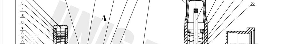
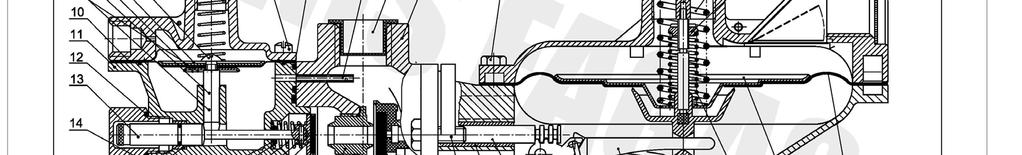
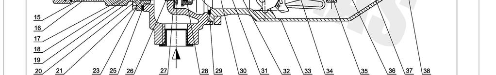
5 Regulator 1853B Part List Item Part number Description Material PCS Seal plug AlCu5PbBi O-ring Vellumoid O-ring Buna N Adjustm.screw AlCu5PbBi Spring mbar C Top TAISi Diaphragm stem screw Steel Upper diaphragm plate Steel 0147HT Lower diaphragm plate Steel 0147HT Stem diaphragm Steel Diaphragm Buna N Body bottom TAISi O-ring Buna N Valve plunger Steel Body plug AlCu5PbBi O-ring Buna N Valve stem quide AlCu5PbBi O-ring valve stem Buna N O-ring retainer Steel Cast-off spring C Roll pin Steel Seat disc, assembly AlCu5PbBi Seat disc Buna N Flange screw Steel Screw Steel O-ring tube Buna N O-ring Buna N X Orifice AlCu5PbBi 1 27 O-ring orifice Buna N Valve Seat disc buna N 80 Buna N O-ring body Buna N Valve body bolt short Steel Plunger quide bush Derlin Valve stem AlCu5PbBi Nylon Lower diaphragm cover TAISi Steel Lever SINT-D P SINT-D Ugst Stem diaphragm Steel Celcon M Spring C Diaphragm plate Steel 0147HT Diaphragm Buna N Valve body tube CuZn Nylon X Valve body NL UPSO screw Steel UPSO Steel Seal plug Ultramid-A Reset rod AlCu5PbBi Gasket Neoprene Press.Adjustm.screw AlCu5PbBi X Pressure spring P Top Top TAISi Flapper vent Steel Retainer vent flapper Steel 0146HT Protect. screen Steel Adj. Spring nut Steel Page5
6 Page 6
7
8
1800C and 1800C-HC Series Service Regulators
 1800C and 1800C-HC Series Service Regulators Installation Instructions www.elster-americanmeter.com General Information: The 1800C and 1800C-HC Regulators are available as Full Capacity Internal Relief
1200B2 Series Service Regulators. Instruction Manual
 00B Series Service Regulators Instruction Manual 00B Series Service Regulators 0 Elster American Meter 00B Series Service Regulators General Information The 00B Series Service Regulators are available
Type S301 & S302 Gas Regulators INTRODUCTION INSTALLATION. Scope of Manual. Description. Specifications. Type S301 and S302. Instruction Manual
 Fisher Controls Instruction Manual Type S301 & S302 Gas Regulators October 1981 Form 5180 WARNING Fisher regulators must be installed, operated, and maintained in accordance with federal, state, and local
American Meter Co. Five-Year Limited Warranty Industrial Regulators
 Read carefully and follow all instructions shipped with this regulator. The incorrect specification or installation of this equipment could result in escaping gas, and pose a potential explosion hazard.
MEGR-1627 Instruction Manual
 MEGR-1627 HIGH FLOW GAS REGULATOR Instruction Manual- Look Inside For: Description Installation Remote Vent Line Installations Startup and Adjustment Shutdown Maintenance Body Maintenance Procedures Diaphragm
MEGR-1912 Instruction Manual
 MEGR-1912 PRESSURE REGULATOR Instruction Manual- Look Inside For: Description Installation Start-Up Maintenance Parts Ordering Parts List Marshall Excelsior Company Marshall, MI 49068 269-789-6700 FAX
1800C and 1800C-HC Service Regulators
 SB 855.9 800C and 800C-HC Service Regulators Maximum Pressure 5 Table of Contents 800C Regulator Information...................... 800C-HC Regulator Information.................. 800C and 8C Service Regulators...............
Types S100K and S102K Pressure Regulators
 Instruction Manual Form 5624 Types S0K and S2K 01/01 Types S0K and S2K Pressure Regulators W7478-1 Figure 1. Types S0K and S2K Pressure Regulator Introduction Scope of Manual This manual provides instructions
299H Series. Introduction. P.E.D. Categories. Specifications. Installation. Warning. Installation Guide English September 2012
 Installation Guide English September 2012 299H Series Introduction This Installation Guide provides instructions for installation, startup, and adjustment of 299H Series regulators. To receive a copy of
Types S108K and S109K Pressure Reducing Regulators with Integral Slam-Shut Device
 Instruction Manual Form 5492 Types S108K and S109K May 1999 Types S108K and S109K Pressure Reducing Regulators with Integral Slam-Shut Device Introduction Fisher regulators must be installed, operated
Model 1800 PFM Series Regulator. Technical Bulletin
 Model 0 PFM Series Regulator Technical Bulletin Model 0 PFM Series Regulator 0 Elster American Meter The 0 PFM Series regulators are designed to control natural gas, air, nitrogen, carbon dioxide, propane
1800CPB2 Service Regulators Maximum Inlet Pressure 125 PSIG
 A C E D SB-8520.2 1800CPB2 Service Regulators Maximum Inlet 125 PSIG AMC Quality System QMI is Accredited by: C R E D I T ISO 9001 Certified Certificate #006697 R E ANSI RAB G I S T R A R Dutch Council
Installation, Operation, and Maintenance Manual
 Installation, Operation, and Maintenance Manual Welker Probe Instrument Regulator Model The information in this manual has been carefully checked for accuracy and is intended to be used as a guide for
2.0 INSTALLATION & SERVICE
 Installation, Operation, and Maintenance Instructions MODEL 5600 / 5600R January 2005 CONTENTS 1.0 GENERAL 1.1 5600 Model Number Information -----------------------------------------------------------------------
1800CPB2 Service Regulators
 SB 8520.5 1800CPB2 Service Regulators Maximum Inlet Pressure 125 PSIG Table of Contents 1800CPB2 Regulator Information................ 2-3 1800CPB2 Capacity Performance................ 4-6 1-1/4" Models,
1805 Series Relief Valves
 Instruction Manual Form 1211 1805 Series October 2011 1805 Series Relief Valves! WARNING Failure to follow these instructions or to properly install and maintain this equipment could result in an explosion
Type ACE97. Introduction. Installation. P.E.D. Categories. Specifications. Overpressure Protection. Installation Guide English May 2002
 Installation Guide English May 2002 Type ACE97 Introduction This installation guide provides instructions for installation, startup, and adjustment. To receive a copy of the instruction manual, contact
Type HSR Pressure Reducing Regulator for Residential, Commercial, or Industrial Applications
 Instruction Manual Form 5753 Type HSR October 2003 Type HSR Pressure Reducing Regulator for Residential, Commercial, or Industrial Applications W8648 Figure 1. Type HSR Pressure Regulator Introduction
Industrial Regulator Series 1800/2000
 E S 85. Industrial Regulator Series / M Quality System QMI is ccredited by: R E I T ISO 9 ertified R E NSI R G I S T R R utch ouncil for ccreditation Measurement Engineers Since 86 merican Meter Series
TECHNICAL DATA CAUTION
 Page 1 of 6 1. DESCRIPTION The Viking Model D-2 Accelerator is a quick-opening device, with an integral anti-flood assembly, used to increase the operating speed of a differential type dry pipe valve.
1800CPB2 Pilot-Loaded Service Regulators
 1800CPB2 Pilot-Loaded Service Regulators Technical Bulletin www.elster-americanmeter.com Table of Contents 1800CPB2 Regulator Information................ 2-3 1800CPB2 Capacity Performance................
Installation, Operation and Maintenance Manual for Back Pressure Regulator
 Installation, Operation and Maintenance Manual for Back Pressure Regulator Model 8860 2009 Groth Corporation IOM-8860 Rev. B 12541 Ref. ID: 95565 Page 2 of 13 Table of Contents I. INTRODUCTION 3 II. DESIGN
WW-730. Pressure Sustaining/Relief Control Valve
 WW-730 Pressure Sustaining/Relief Control Valve Installation Operation & Maintenance Page 1 of 6 1. DESCRIPTION The Model 730 Pressure Relief / Sustaining Valve is an automatic control valve designed to
Model: 43T. Bermad Pressure Relief Valve
 Model: 43T Bermad Pressure Relief Valve Installation Operation Maintenance Manual () Rev.C1_01.08.17 Page 1 of 10 Safety First BERMAD believes that the safety of personnel working with and around our equipment
Model: 720-UL INSTALLATION OPERATION MAINTENANCE. Bermad Pressure Reducing Valve IOM. Model: FP -720-UL Sizes: 2"-12" BERMAD. Application Engineering
 Bermad Pressure Reducing Valve Model: 720-UL INSTALLATION OPERATION MAINTENANCE Application Engineering BERMAD 1. Safety First BERMAD believes that the safety of personnel working with and around our equipment
CS800 Series Commercial / Industrial Pressure Reducing Regulators
 Instruction Manual D103124X012 CS800 Series April 2018 CS800 Series Commercial / Industrial Pressure Reducing Regulators P1235 P1234 TYPE CS800 REGULATOR TYPE CS800IQ WITH HIGH CAPACITY RELIEF P1521 TYPE
RS(H)10,15 USER MANUAL. Read the complete manual before installing and using the regulator.
10,15 USER MANUAL. Read the complete manual before installing and using the regulator.") RS(H)10,15 USER MANUAL Read the complete manual before installing and using the regulator. WARNING INCORRECT OR IMPROPER USE OF THIS PRODUCT CAN CAUSE SERIOUS PERSONAL INJURY AND PROPERTY DAMAGE. Due to
RS(H)10,15 USER MANUAL Read the complete manual before installing and using the regulator. WARNING INCORRECT OR IMPROPER USE OF THIS PRODUCT CAN CAUSE SERIOUS PERSONAL INJURY AND PROPERTY DAMAGE. Due to
Installation Troubleshooting Maintenance Instructions Installation / Start-up
 Model ZW207 Installation Troubleshooting Maintenance Instructions Installation / Start-up NOTE: Flushing of all pipe lines is to be performed to remove all debris prior to installing valve. 1. For making
Product Manual. Description. Specifications. CVS Type 1301F and CVS Type 1301G Regulator. Introduction
 Product Manual CVS Type 1301F and CVS Type 1301G Regulator Introduction This CVS Controls product manual includes instructions for the installation, adjustment, maintenance and parts ordering of the CVS
Models 461-S, 461-8S and S Regulators. R-1330 Rev. 7
 Models 461-S, 461-8S and 461-12S Regulators R-1330 Rev. 7 461-S, 461-8S and 461-12S Regulators The Sensus Models 461-S, 461-8S and 461-12S are balanced valve, spring type regulators designed for distribution
1305 Series Pressure Reducing Regulators
 Instruction Manual Form 1095 1305 Series October 2009 1305 Series Pressure Reducing Regulators! Warning Fisher regulators must be installed, operated, and maintained in accordance with federal, state,
RHPS Series RD(H)F40 User Manual. Read the complete manual before installing and using the regulator.
F40 User Manual. Read the complete manual before installing and using the regulator.") RHPS Series RD(H)F40 User Manual Read the complete manual before installing and using the regulator. 2 WARNING Before removing a regulator from the system for service, you must depressurize system purge
RHPS Series RD(H)F40 User Manual Read the complete manual before installing and using the regulator. 2 WARNING Before removing a regulator from the system for service, you must depressurize system purge
INSTALLATION INSTRUCTIONS. CVS 67CFR Pressure Reducing Instrument Supply Regulator INTRODUCTION
 INSTALLATION INSTRUCTIONS CVS 67CFR Pressure Reducing Instrument Supply Regulator INTRODUCTION The CVS Controls 67CFR Filter regulator is a pressure reducing supply regulator typically used for pneumatic
Bermad Pressure Reducing. Model: 42T
 Bermad Pressure Reducing Pilot Operated Pressure Control Valve Model: 42T Installation Operation Maintenance Manual (IOM) REV. 27.7.17 Page 1 of 12 Safety First BERMAD believes that the safety of personnel
627 Series Pressure Reducing Regulators
 627 Series Pressure Reducing Regulators Introduction The 627 Series direct-operated pressure reducing regulators (Figure 1) are for low and high-pressure systems. These regulators can be used with natural
Model 141-A Regulators
 Regulator Installation and Maintenance Instructions Model -A Regulators RM- Rev. Introduction The Model -A regulator is both easy to use and durable for high pressure jobs. Thus, these field regulators
CSB400 Series Commercial / Industrial Pressure Reducing Regulators
 CSB400 Series Commercial / Industrial Pressure Reducing Regulators Bulletin 71.1:CSB400 April 2011 CSB400 SERIES PRESSURE REDUCING TYPICAL CSB403 WITH INTEGRAL TRUE-MONITOR TYPICAL CSB404 WITH INTEGRAL
Types 749B and R130 Changeover Manifolds
 Instruction Manual MCK-1179 Types 749B and R130 June 2012 Types 749B and R130 Changeover Manifolds TYPE HSRL-749B TYPE 64SR/122 TYPE R130/21 TYPE 749B/21 Figure 1. Changeover Manifolds and Regulator Assemblies
SR100 Series Service Regulators. Technical Bulletin
 SR00 Series Service Regulators Technical Bulletin Model SR00 Series Regulator 0 Elster American Meter The compact, high capacity SR service regulator is designed for residential or light commercial/industrial
V43 Pressure Actuated Water Regulating Valve
 FANs 125, 121 Product/Technical Bulletin V43 Issue Date 0996 V43 Pressure Actuated Water Regulating Valve The V43 Pressure Actuated Water Regulating Valves are designed to regulate water flow for water-cooled
Combination Air Valve
 Combination Air Valve For Sewage and Wastewater Model C50 Installation, Operation and Maintenance Manual (IOM) Table of Contents General... Page 2 Safety... Page 2 Operational Data... Page 3 Materials
Anti-flood device Model B-1
 December 4, 2009 Dry Systems 123a 1. DESCRIPTION The Anti-flood Device is required when Viking accelerators are installed on dry systems according to Viking Model E-1 Accelerator Trim Charts. In the SET
64 Series Pressure Reducing Regulators
 Instruction Manual Form 1245 64 Series March 2006 64 Series Pressure Reducing Regulators W1943 Figure 1. 64 Series Regulator Introduction Scope of Manual This manual provides instructions for the installation,
CL34 Regulator Commercial and Industrial Regulator
 CL34 Regulator Commercial and Industrial Regulator Appropriate for commercial and industrial applications where very accurate pressure control is required such as fixed-factor metering applications or
Welker Sampler. Model GSS-1. Installation, Operation, and Maintenance Manual
 Installation, Operation, and Maintenance Manual Welker Sampler Model GSS-1 The information in this manual has been carefully checked for accuracy and is intended to be used as a guide to operations. Correct
THE HF-300 SERIES. Operating and Service Manual. Series includes all variants of HF-300/301
 THE HF-300 SERIES Operating and Service Manual Series includes all variants of HF-300/301 Issue A July 2015 1 TABLE OF CONTENTS 1. Description... 3 2. Installation... 3 3. Operation... 4 3.1. Spring Loaded...
299H Series Pressure Reducing Regulators
 Instruction Manual Form 5497 299H Series January 2014 299H Series Pressure Reducing Regulators! WARNING Failure to follow these instructions or to properly install and maintain this equipment could result
299H Series Pressure Reducing Regulators
 Instruction Manual D102684012 299H Series May 2017 299H Series Pressure Reducing Regulators! Warning Failure to follow these instructions or to properly install and maintain this equipment could result
Installation Operation Maintenance. Bermad Level Control Valve with Modulating Horizontal Float Pilot valve One Way Flow IOM.
 Bermad Level Control Valve with Modulating Horizontal Float Pilot valve One Way Flow Model: FP 450-80 Installation Operation Maintenance PAGE 1 OF 5 1. Safety First BERMAD believes that the safety of personnel
SUBMITTAL NOTES PROJECT: Ross Model 50RWR-A Pilot Operated Surge Relief Valve with Hydraulic Anticipation. Size: inch / mm
 SUBMITTAL NOTES PROJECT: Ross Model 50RWR-A Pilot Operated Surge Relief Valve with Hydraulic Anticipation Size: inch / mm Every Ross Valve shall be hydrostatically tested for body integrity and tight seating
TECHNICAL DATA ANTI-FLOOD DEVICE MODEL B-1 1. DESCRIPTION
 Page 1 of 6 1. DESCRIPTION The Model B-1 Anti-flood Device is required when Viking accelerators are installed on dry systems according to Viking Model E-1 Accelerator Trim Charts. In the SET condition,
Type OS2 Slam-Shut Device
 Instruction Manual D102778X012 Type OS2 April 2018 Type OS2 Slam-Shut Device! Warning Failure to follow these instructions or to properly install and maintain this equipment could result in an explosion
299H Series Pressure Reducing Regulators
 September 12 299H Series Pressure Reducing Regulators Inlet Pressure up to psig / 1 bar Compact ±1% Accuracy for Fixed Factor Billing (PFM) Rugged Construction Integral Pilot Easy to Maintain W713 Figure
INSTALLATION, OPERATION, AND MAINTENANCE MANUAL WELKER RELIEF VALVE
 INSTALLATION, OPERATION, AND MAINTENANCE MANUAL WELKER RELIEF VALVE MODELS RV-1 RV-2 RV-2CP RV-3 DRAWING NUMBERS AD017A[ ] AD018A[ ] AD020A[ ] AD282BO MANUAL NUMBER IOM-033 REVISION Rev. E, 3/28/2016 TABLE
LRS(H)4 Pressure-Reducing Regulator User Manual
4 Pressure-Reducing Regulator User Manual") LRS(H)4 Pressure-Reducing Regulator User Manual Read the complete manual before installing and using the regulator. 2 Safe Product Selection When selecting a product, the total system design must be considered
LRS(H)4 Pressure-Reducing Regulator User Manual Read the complete manual before installing and using the regulator. 2 Safe Product Selection When selecting a product, the total system design must be considered
299H Series Pressure Reducing Regulators
 Instruction Manual D102684012 299H Series May 2018 299H Series Pressure Reducing Regulators! Warning Failure to follow these instructions or to properly install and maintain this equipment could result
WW-720. Pressure Reducing Control Valve
 WW-720 Pressure Reducing Control Valve (Size Ranges: 2-4 and 6-14 ) Installation Operation & Maintenance Page 1 of 6 1. DESCRIPTION The Model 720 Pressure Reducing is an automatic control valve (powered
1800C & 1800C-HC Service Regulators
 SB-855.8 800 & 800-H Service Regulators Maximum Pressure 5 PSIG 800 Regulator Information General Information The merican Meter Series 800 pressure regulators are designed for natural gas applications
Types S100C and S102C Pressure
 Instruction Manual Form 5404 Types S100C and S102C Types S100C and S102C Pressure Regulators Introduction Scope of Manual This manual provides instructions for the installation, adjustment, maintenance
Type CT88 Backpressure Regulator
 Instruction Manual Type CT88 July 2016 Type CT88 Backpressure Regulator Table of Contents Introduction...1 Specifications...2 Principle of Operation...2 Installation...3 Overpressure Protection...4 Startup...4
TECHNICAL INSTRUCTIONS
 TECHNICAL INSTRUCTIONS Hydroguard Series 410 Valves Model 5 and Model 8 Form TI410-5 v3 DESCRIPTION The Series 410 Hydroguard is a pressure compensating mixer which delivers a predetermined water temperature,
CL34 Regulator Commercial and Industrial Regulator
 CL34 Regulator Commercial and Industrial Regulator Appropriate for commercial and industrial applications where very accurate pressure control is required such as fixed-factor metering applications or
Model 1800 PFM Series Regulator For Constant Outlet Pressure Precise Fixed Factor Measurement From 0.5 to 30 PSIG
 A C E D SB 8551.3 Model 1800 PFM Series Regulator For Constant Precise Fixed Factor Measurement From 0.5 to 30 G AMC Quality System QMI is Accredited by: C R E D I T ISO 900 Registered R E ANSI RAB G I
Radial Flow Valves. Installation Operation Control Manifold Control Loops Repair Parts. ANSI Class 150, 300 and 600 IM
 IM 9730.1 ANSI Class 150, 300 and 600 Radial Flow s Installation Operation Manifold Loops Repair Parts AMC Quality System QMI is Accredited by: ISO 9002 Registered Dutch Council for Accreditation INDEX
RD(H)20/25 Pressure-Reducing Regulator User Manual
20/25 Pressure-Reducing Regulator User Manual") RD(H)20/25 Pressure-Reducing Regulator User Manual Read the complete manual before installing and using the regulator. 2 Safe Product Selection When selecting a product, the total system design must be
RD(H)20/25 Pressure-Reducing Regulator User Manual Read the complete manual before installing and using the regulator. 2 Safe Product Selection When selecting a product, the total system design must be
Type ACE95jr Tank Blanketing Valve
 Instruction Manual Form 5666 Type ACE95jr 04/01 Type ACE95jr Tank Blanketing Valve W8157 Introduction Scope of Manual Figure 1. Type ACE95jr Tank Blanketing Valve This instruction manual provides installation,
Operation Manual Piston Sensed Gas Pressure Regulators
 687 Technology Way Napa, CA 94558 Phone: (707) 259-0102 FAX: (707) 259-0117 www.aptech-online.com Operation Manual Piston Sensed Gas Pressure Regulators (Models KT9, KT10, Welded KT10, KT12) Table of Contents:
36E DSI, HSI & Proven Pilot Two-Stage Combination Gas Valve INSTALLATION INSTRUCTIONS
 INLET PRESS TAP WTE-RODGERS 36E96-314 DSI, HSI & Proven Pilot Two-Stage Combination Gas Valve INSTALLATION INSTRUCTIONS Operator: Save these instructions for future use! FAILURE TO READ AND FOLLOW ALL
WW-720. Pressure Reducing Control Valve
 WW-720 Pressure Reducing Control Valve (Size Ranges: 2-4 and 6-14 ) Installation Operation & Maintenance Page 1 of 6 1. DESCRIPTION The Model 720 Pressure Reducing is an automatic control valve (powered
Engineering Data Sheet
 Page 1 of 6 CE MARKING AND THE PRESSURE EQUIPMENT DIRECTIVE 97/23/EC Valves must be installed into a well designed system and it is recommended that the system be inspected in accordance with the appropriate
627 Series Pressure Reducing Regulators
 Instruction Manual Form 5252 627 Series December 2006 627 Series Pressure Reducing Regulators NUMBER 1 10B3679-D NUMBER 2 W4793 Figure 1. Typical 627 Series Self-Operated Pressure Reducing Regulator Introduction
HIGH RATE BASKET STRAINER
 Installation and Operation Instruction Manual INSMAN-105 High Rate Basket Strainer Phone: 951.656.6716 Toll-Free: 800.854.4788 www.yardneyfilters.com Yardney Water Management Systems, Inc. 6666 Box Springs
TECHNICAL DATA. Q = C v P S
 Page 1 of 13 1. DESCRIPTION The Viking 6 Model G-6000 Dry Valve Riser Assembly consists of a small profile, light weight, pilot operated valve that is used to separate the water supply from the dry sprinkler
Operation & Maintenance Manual Place this manual with valve or person responsible for maintenance of the valve
 Operation & Maintenance Manual Place this manual with valve or person responsible for maintenance of the valve Model CYCLE GARD II, CI & CNA YOUR PRODUCT INFORMATION: Model Number: Date: Serial Number:
R122H, R222, R232A, and R232E Series Instruction Manual
 Instruction Manual MCK 2156 R122H, R222, R232A, and R232E Series October 2012 R122H, R222, R232A, and R232E Series Instruction Manual Failure to follow these instructions or to properly install and maintain
Mounting and operating instructions EB 2530 EN. Self-operated Pressure Regulator. Pressure Reducing Valve Type M 44-2
 Self-operated Pressure Regulator Pressure Reducing Valve Type M 44-2 Type M 44-2, connection G 1 4, K VS = 0.15 Type M 44-2, connection G 1, K VS = 6 Fig. 1 Type M 44-2 Pressure Reducing Valve Mounting
I T T Pressure Reducing Valve WARNING INSTALLATION, OPERATION, AND MAINTENANCE MANUAL
 INSTALLATION, OPERATION, AND MAINTENANCE MANUAL I-867-4T 867-4T Pressure Reducing Valve HANG THESE INSTRUCTIONS ON THE INSTALLED VALVE FOR FUTURE REFERENCE WARNING Read and understand all instructions
LRS(H)4 USER MANUAL. Read the complete manual before installing and using the regulator.
4 USER MANUAL. Read the complete manual before installing and using the regulator.") LRS(H)4 USER MANUAL Read the complete manual before installing and using the regulator. WARNING INCORRECT OR IMPROPER USE OF THIS PRODUCT CAN CAUSE SERIOUS PERSONAL INJURY AND PROPERTY DAMAGE. Due to the
LRS(H)4 USER MANUAL Read the complete manual before installing and using the regulator. WARNING INCORRECT OR IMPROPER USE OF THIS PRODUCT CAN CAUSE SERIOUS PERSONAL INJURY AND PROPERTY DAMAGE. Due to the
APCO ARV CLEAN WATER AIR RELEASE VALVES. Model 50A
 APCO ARV CLEAN WATER AIR RELEASE VALVES Model 50A Instruction D12013 February 2017 Instructions These instructions provide installation, operation and maintenance information for APCO ARV Clean Water Air
Type ACE97 Pad-Depad Valve
 Instruction Manual Form 5665 Type ACE97 November 2011 Type ACE97 Pad-Depad Valve DEPAD PILOT VALVE DEPAD MAIN VALVE W8161 ACTUATOR VENT GAS INLET PAD VALVE TO TANK Figure 1. Type ACE97 Pad-Depad Valve
INDUSTRIAL VALVES MODELS: C62-A; C62-D. INSTRUCTION MANUAL Installation Operation Parts Service DIAPHRAGM BYPASS PRESSURE REGULATING VALVES
 INSTRUCTION MANUAL Installation Operation Parts Service IMPORTANT Record your Regulator model number and serial number here for easy reference: Model No. Serial No. Date of Purchase When ordering parts
CSB400 Series Commercial / Industrial Pressure Reducing Regulators
 October 2015 CSB400 Series Commercial / Industrial Pressure Reducing Regulators P1424 TYPE CSB400 PRESSURE REDUCING P1426 TYPICAL TYPE CSB403 WITH INTEGRAL TRUE-MONITOR P1425 TYPICAL TYPE CSB404 WITH INTEGRAL
Types 95L and 95H Pressure Regulators
 Instruction Manual Form 1151 Types 95L and 95H July 1990 Types 95L and 95H Pressure Regulators W1888 W1888 W5652 Figure 1. NPT Body (Left), NPT Body (Middle), and Flanged Body (Right) Pressure Regulators
61R2 STANDARD REGULATOR COMPACT REGULATOR. Phone Fax
 6R STANDARD REGULATOR COMPACT REGULATOR 496 Phone 7.63.888 Fax 7.63.690 6R AND 496 REGULATORS General Information The Model 6R and 496 Compact Regulator (CR) are designed to deliver reliable and safe regulation
Wilo Triple Duty Valve / Triple Service Valve Installation and operating instructions
 Wilo Triple Duty Valve / Triple Service Valve Installation and operating instructions WIL-IO-SD-001-10 1 Description The Triple Duty Valve (TDV) / Triple Service Valve (TSV) is a quiet operating heavy-duty
Float Operated Level Controllers
 CONTENTS Float Operated Level Controllers IM0015 Nov. 2014 PAGE Introduction 1 Scope 1 Description 1 Specification 1 Control Installation 2 INTRODUCTION Side Mount Back Mount Prior to installing, the instructions
CL31 Series Commercial Regulator. Advanced Metering and Regulation Technology at Work.
 IMAC Systems, Inc. 90 Main Street, PO Box 1605 Tullytown, PA 19007 Tel. 1-800-955-4GAS (215) 946-2200 Fax:(215) 943-2984 www.imacsystems.com CL31 Series Commercial Regulator Advanced Metering and Regulation
Series 100 Slam Shut Valve. Technical Bulletin
 Series 100 Slam Shut Valve Technical Bulletin 02 Elster The Series 100 Slam Shut protects gas installations against overpressure conditions by automatically shutting off the gas flow. General Information
Anderson Greenwood Series 93 Positive Pressure POSRV Installation and Maintenance Instructions
 Before installation these instructions must be fully read and understood Installation and maintenance instructions for Series 93 Positive Pressure Pilot Operated Safety Relief Valves (POSRV). The intent
CL38 Regulator Commercial & Industrial Regulator
 Gas CL38 Regulator Commercial & Industrial Regulator Applications Appropriate for commercial and industrial applications where very accurate pressure control is required such as fixed-factor metering applications
Operation Manual. Diaphragm Sensed Gas Pressure Regulators
 687 Technology Way Napa, CA 94558 Phone: (707) 259-0102 FAX: (707) 259-0117 www.aptech-online.com Diaphragm Sensed Gas (AP/AZ/AK Models: 20, 100, 500, 1000, 1000T 10PA, 1100, 1200, 12PA, 1300, 1400T, 14PA,
OPERATING AND MAINTENANCE MANUAL
 Series 4300 Engineered Performance TABLE OF CONTENTS 0 INTRODUCTION 1 1 Scope 1 2 Description 1 3 Specifications 1 0 INSTALLATION 1 1 Mounting 1 2 Piping 1 1 Connecting Process Pressure 2 2 Vent Connections
1213B2 Service Regulators Maximum Inlet Pressure 125 PSIG
 SB-8506. B Service Regulators Maximum Inlet Pressure 5 PSIG Measurement Engineers Since 86 www.americanmeter.com B Service Regulators General Information The American Meter Series B pressure regulator
R600 and HSRL Series Instruction Manual
 Instruction Manual MCK 2141 November 2009 R600 and HSRL Series Instruction Manual! Warning Failure to follow these instructions or to properly install and maintain this equipment could result in an explosion
CL231 Series Regulator Commercial Regulator
 Gas CL231 Series Regulator Commercial Regulator Applications The CL231 regulator is designed primarily for use in medium size commercial and industrial installations requiring highly accurate pressure
Installation, Operation, and Maintenance Manual
 Installation, Operation, and Maintenance Manual Welker Instrument Supply Pressure System Model WIC The information in this manual has been carefully checked for accuracy and is intended to be used as a
Type R622 Pressure Reducing Regulator
 Type R622 Pressure Reducing Regulator June 2010 Compact Design Protective Inlet Screen High Capacity Internal Relief Light Weight W8806 Inlet and Outlet Pressure Gauge Taps Figure 1. Type R622 Pressure
TECHNICAL DATA 3 MODEL G-3000 DRY VALVE RISER ASSEMBLY
 Page 1 of 13 1. DESCRIPTION The Viking 3 Model G-3000 Dry Valve Riser Assembly is equipped with a small profile, light weight, pilot operated valve that is used to separate the water supply from the dry
A3S Bellows Sealed Stop Valve Installation and Maintenance Instructions
 1326050/3 IM-P132-11 ST Issue 3 A3S Bellows Sealed Stop Valve Installation and Maintenance Instructions 1 General safety information 2 General product information 3 Installation 4 Commissioning 5 Operation
DN 50 REGULATOR SUTON 5000A1 REGULATOR SUTON 5000D1
 www.apq.com.es EU Product / Spain DN 50 REGULATOR SUTON 5000A1 REGULATOR SUTON 5000D1 Cod. RISUT5000A1 Cod. RISUT5000D1 DESCRIPTION The Suton 50001 Regulator is designed for use in distribution networks