1. PARTS INTRODUCTION ELECTRICAL NOTES INSTALLATION 5/6. 5. START UP 6/7. 6. MAINTENANCE 7/8/9. 7. PRESSURE SWITCH ADJUSTMENTS 9/10.
|
|
|
- Vanessa Greene
- 5 years ago
- Views:
Transcription


1
2 CONTENTS 1. PARTS INTRODUCTION ELECTRICAL NOTES INSTALLATION 5/6. 5. START UP 6/7. 6. MAINTENANCE 7/8/9. 7. PRESSURE SWITCH ADJUSTMENTS 9/ ELECTRICAL CONNECTIONS 10/ SPECIFICATIONS DECLARATIONS of CONFORMITY RECYCLING 13. PAGE 2

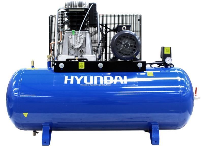
3 1. PARTS. PAGE 3
4 2. INTRODUCTION. Read this manual carefully before installing, using or carrying out any maintenance on your compressor. This instruction manual has been written to simplify installation, maintenance and general use of your new compressor. Strict observance to the content of this manual is essential to ensure a correct and economical operation of the compressor. The Warning notes, underline those operations which, if not carried out correctly could cause damage to the equipment and injury to the user. We strongly recommend only genuine Hyundai replacement spare parts are used, which will guarantee the efficiency and service life of the compressor. N.B. Warning Use of non-genuine parts invalidates our warranty on your compressor. INSTALLATION. Having removed the compressor from it s packaging and check that it is in perfect condition; you are now ready to install your new compressor as follows: 2.1 Portable compressors. Fit the wheels and rubber foot as required (Fig 1). Continue as stationary Stationary compressors. 2.2a Site the compressor on a level surface in a clean dry area (Fig 4). It is essential the compressor should has a 1 metre clearance from the surrounding walls and 2 metres from the ceiling to ensure proper ventilation and efficient cooling. If the compressor is sited in a small room there must be a minimum of two air changes per min to provide adequate ventilation. To achieve this it may require the use of both an input and extract fans to ensure the room temperature does not exceed 40 C. 2.2b It is further recommended that compressors used for painting be located in a separate room, away from the area where sanding/grinding and painting is done. Abrasive particles or paint found to have clogged the air intake filter and valves shall automatically void warranty. N.B. Minimum Working temperature +5 C 2.2c Compressors that are receiver mounted or skid-base packages should not be bolted to the floor but installed on anti-vibration mounts. When using anti-vibration mounts it is essential to use a flexible pipe to connect the compressor to the installed system. 2.2d Air leaks if not corrected will cause excess wear in the compressor and can result in the compressor not being able to provide the air required. PAGE 5
5 3. ELECTRICAL NOTES. 3.3 Always use a qualified electrician to connect the compressor to the mains. Check electrical supplies match compressor specification as per the motor information plate (fig 6). 3.4 All compressors are supplied with a power cable of 2 metres for connection to a fused isolator close to the compressor. (not supplied) sited close to the compressor. 3.5 Single phase compressors can be fitted with an appropriate plug (Fig 5) & (Table 1). It is extremely important that attention is, paid to the technical data sheet to establish the correct fuse and plug are used for the particular compressor in question. N.B. Warning Failure to use the correct plug and fuse could cause damage to the equipment and injury to the user, and will invalidate the warranty. Three phase 2hp to 7.5hp compressors are fitted with a direct on line starter/pressure switch complete with 2 metres of cable for connection to a fused isolator (not supplied). A 10hp three phase compressor is supplied with a star-delta starter, which is pre-wired with 2 metres of cable. The starter should be connected to a fused isolator (not supplied). TABLE 1 HP Supply voltage Fuse / Plug type 2-3* 230/1/50 13 amp flat 3 pin - EEC /1/50 32 amp 3 pin - EEC /3/50 16 amp 4 pin - EEC /3/50 32 amp 4 pin - * Only compressors fitted with soft start and low current motors can be used with 13 amp plugs. TANDEM/DUPLEX COMPRESSORS Installation for these compressors requires a qualified electrician to connect the compressor to the mains. Both tandem and duplex compressors (two pumps on same receiver) are supplied with a timed starter to make sure that there is a time lapse between each compressor starting. 4. INSTALLATION. Secure starter panel (when supplied) to the wall or a fixed support and connect to a fused isolator adjacent to the control panel, or connect power cable direct to fused isolator (not supplied). Cable to the isolator should be suitable for the total HP/Kw been used (see Table 2). If an extension to the supply is required, it should have a cross section for the wires in proportion to its length, (see Table 2). VALID SECTION FOR A MAXIMUM LENGTH OF 20 METRES TABLE 2 HP/kw 220/230 Volt 380/400 Volt / sq mm 1.5 sq mm 5.5/4 2.5 sq mm 2.5 sq mm 10/ sq mm 20/15 10 sq mm N.B. Warning any extension of supply cable should not be less in section than the cable fitted to the compressor by the factory. PAGE 6
6 CAUTION Never use the ground clamp in place of the neutral clamp to provide a single phase supply. Earthing connections must be carried out in accordance with the safety regulations (EN60204). The power cable plug or socket/isolator must not be used to stop the compressor, as this could cause damage to the compressor when restarting. Always stop compressor via the pressure switch (Fig 7) on/off button. Always use a suitably fused isolator sited close to the compressor. The isolator should preferably be fitted with a trip to avoid damage to the motor due to the loss of a phase. The compressor pump and delivery pipe can reach very high temperatures. Use extreme caution when working in the proximity of these parts. To avoid burns, do not touch these parts (Fig 11). 5. START UP. 5.1 Compressors with DOL & Star/delta starters (Single/Three Phase). 5.1a Check that the line voltage corresponds to the motor data plate (Fig 6), tolerance must not exceed + or - 5%. 5.1b Turn switch on pressure switch to position O (OFF) (Fig 7). Connect to mains and switch power on. 5.1c Turn switch on pressure switch to position 1 (ON) (Fig 7). Compressor will now start. The pressure switch will automatically control the stopping and starting of the compressor to the factory standard settings. 5.1d Check the rotation of the compressor as this is of particular importance to ensure the correct cooling and lubrication of the compressor. See arrow on motor and fly wheel. (Fig 12). N.B. Warning Because an automatic pressure switch controls the compressor, the compressor will start without warning. 5.2 Compressors with tandem and duplex starters. 5.2a Turn switch on pressure switch to position O (OFF) (Fig 7). 5.2b Select the duty cycle by turning the control knob to the required setting (Fig 9). 5.2c Turn switch on pressure switch to position 1 (ON) (Fig 7). Compressor will now start and be controlled in accordance with the duty selected. The pressure switch will automatically control the stopping and starting of the compressor to the factory standard settings. Position 1 Position 3 Position 2 Only number one compressor runs Only number two compressor runs Both compressors run N.B. Warning Because an automatic pressure switch controls the compressor, the compressor will start without warning. 5.3 Overload protection. 5.3aThe single phase electric motors are equipped with an amperometric thermal cutout with manual reset located on the terminal box at the top of the electric motor. When the thermal cut-out intervenes, wait several minutes, then manually reset the thermal switch (Fig 12). PAGE 6
7 With three phase compressors, the cut-out is automatic and is located inside the pressure switch. When the thermal cut-out intervenes, the pressure switch cuts-out and moves to the position O (OFF)(Fig 7), wait 10 minutes and turn the pressure switch back to position 1 (ON) (Fig 7). With compressors equipped with a wall mounted starter the thermal cut-out is located on the inside of the starter unit. When the thermal cut-out intervenes, turn the pressure switch to position O (OFF) (Fig 7), wait several minutes, then manually reset the thermal overloads. To Reset thermal overloads push the blue reset buttons on the front cover of the wall mounted starter unit. Restart the compressor by the steps described in the section Start Up 6. MAINTENANCE. CAUTION Before performing any maintenance on the compressor make sure that: The compressor is isolated from the electrical supply. The pressure switch and switches on the power unit are turned to position OFF. The receiver is drained of any compressed air. 6.1 Cleaning and changing filter cartridge. Clean the air intake filters every month by blowing compressed air from the inside of the filter to the outside of the filter or cartridge (Fig. 14). We recommend replacing the filter cartridge or filter element at least twice a year if the compressor operates in a clean environment and more frequently if the compressor is located in a dusty environment. 6.2 General maintenance. Check the tension of the belts every month and adjust them if necessary. Release the condensate from the air receiver at least once a day by opening the discharge tap (Fig. 15). Thoroughly clean all external parts of the compressor and motor every 6 months or 2000 running hours to ensure proper cooling. 6.3 Oil. Check oil level every day (Fig. 3) when compressor is cold, top up as necessary. Use Hyundai 100 OIL or SAE10W/30 engine oil. 6.4 Oil change. Remove the drain plug (Fig 16) to drain the oil and then re-fit drain plug. Top up to the appropriate oil level as (Fig 3). FIAC 100 oil should be changed every 6 months or 2000 running hours which ever is reached first. Alternatively you can use or SAE10W/30 engine oil, Oils other than FIAC 100 should be replaced every 3 months or 250 hours. PAGE 7
8 6.5 Emergency STOP button (TANDEM ONLY). The emergency stop button (Fig17) is located on the wall-mounted starter this allows the compressor to be stopped in an emergency. DO NOT USE THIS SWITCH AS A POWER SWITCH. To reset the emergency button, rotate the red knob anti-clockwise a half turn. To restart the compressor refer to START UP (Page 4) relevant to your compressor. 6.6 How to fix minor faults. 6.6a Air leak from pressure switch valve.these are caused by air leaking from the receiver through the non-return valve. 6.7 How to fix it. (Fig. 18). 6.7a Empty the tank of compressed air completely. 6.7b Unscrew the hexagonal head of the valve (Fig. 18) (A). 6.7c Clean or replace the rubber disk (Fig. 18) (B) and clean the housing thoroughly. 6.7d Re-assemble the unit carefully. 6.8 The compressor runs but does not produce air. 6.8a Check the inlet and outlet valves (Fig. 19) and gasket for damage. 6.8b Replace damaged parts using Service Kit No.1. WARNING Never unscrew any joints with the air receiver under pressure, always ensure that the air receiver is empty of compressed air. Do not work on the compressor without disconnecting the unit from the electrical power supply. Ambient working temperature range +5 C to +40 C Do not direct water or inflammable liquids towards the compressor. Do not place inflammable objects near the compressor. Do not place any articles on or near the compressor, this will impede the cooling and could cause a fire. When the compressor is not being used turn the pressure switch to the OFF position. (Fig. 7). Never direct compressed air at persons or animals. Do not transport the compressor with the tank under pressure. Keep children and animals away from the area where the machine is operating. After using the compressor always disconnect from the electrical supply. 6.9 If the compressor is used for painting. 6.9a Do not operate the compressor in closed spaces or in the proximity of naked flames and spray vapour. 6.9b Make sure that the room where you are working has a Sufficient change of air (Min 2 per minute, see installation notes). (Fig. 20). 6.9c Use an appropriate mask to protect nose and mouth (Fig. 20). PAGE 8

9 Compressed air receivers for the European market are built in accordance with EC Directive 09/105. Air Compressors for the European market are built in conformity with the Directive 2006/42/EC 7. PRESSURE SWITCHADJUSTMENTS. NE-MA Single Phase N.B. Warning Switch off power at fused isolator before making any adjustment to the pressure-switch. 7.1 NE-MA pressure switch is supplied with a standard cut out pressure 150 psi and a cut in pressure of 120 psi. 7.2 The cut out setting can be adjusted to suit your individual requirement as follows: 7.1a Increase or decrease cut out pressure. Adjust (A) clock wise to increase, anti-clock wise to decrease (Fig 21). N.B. Warning Pressuremust not exceed maximum working pressure of the receiver. NE-MA Fig 21 EN PED 97/23 CEE A Pressure Switch Adjustment PAGE 9

10 MDR-3 Three Phase N.B. Warning Switch off power at fused isolator before making any adjustment to the pressure-switch. 7.3 MDR-3 pressure switch is supplied with a standard cut out pressure 150 psi and a cut in pressure of 120 psi. 7.4 Both these settings can be adjusted to suit your individual requirement as follows: 7.4a Increase or decrease cut out pressure. Adjust the central upper pressure screw (A) clockwise to increase or anti-clockwise to decrease (Fig b Increase or decrease differential pressure. With a screwdriver adjust the pressure differential screw (B) clockwise to increase, anti-clock wise to decrease (Fig 23). Note: From time to time the pressure switch settings may vary and should be adjusted as per above (This is NOT covered by warranty). MDR 3 Fig 22 MDR 3 Fig 23 THREE PHASE ATTENTION Adjustments are to be carried out only when the switch is mounted, under pressure and voltage free. TOP VIEW 0.4 Nm Tightening Torque MAINS MOTOR Upper Pressure Setting (A) Pressure Differential (B) 8. ELECTRICAL CONNECTIONS. ELECTRIC MOTOR TERMINAL BOARD CONNECTION 230/50/1 MOTORS 400/50/3 MOTORS STAR DELTA 400/50/3 MOTORS D.O.L. W2 U2 V2 U1 V1 W1 PAGE 10
11 STAR DELTA 400/50/3 TANDEM STARTER CIRCUIT DIAGRAM 230/50/1 PAGE 11
12 9. SPECIFICATIONS. Model HY HY Voltage - V Number of phases 3 3 Frequency Hz Connection method/cable length m Hard wired - 3 pin + earth industrial plug Hard wired - 3 pin + earth industrial plug Motor power hp/kw 5.5/4 7.5/5.6 Rated Speed (motor) RPM Maximum Pressure - PSi/Bar 145/10 145/10 Cut-out Pressure - PSi/Bar 120/ /8.3 Cut-in Pressure - PSi/Bar 87/6 87/6 Tank Capacity - L Free air delivery - CFM - L/min 16.5/476 21/595 Displacement - CFM/L/min 23/651 29/821 Air Outlet Valve Tap/½" BSP Valve Tap/½" BSP Output pressure regulation type Fixed Fixed Drive type Belt Belt Overall Unit Dimensions L x W x H mm 1520 x 480 x x 500 x 1040 Net Weight - kg Tank material Rolled steel Rolled steel 10. DECLARATIONS of CONFORMITY. Compressor models HY & HY Designed & produced in accordance with the following Machinery Directive 2006/42/EC Supply of Machinery (Safety) Regulations 2008 Supply of Machinery (Safety) Amendment Regulations 2011 EU Directive 2000/14/EC (2005/88/EC) Apply to air receiver: Simple Pressure Vessels Directive 2009/105/EC Simple Pressure Vessels (Safety) Regulations 1991 Simple Pressure Vessels (Safety) Amendment Regulations 1994 EN286-1 Unfired Pressure Vessels Apply to safety valve: Pressure Equipment Directive 1997/23/EC The Pressure Equipment Regulations 1999 ISO 4126;.1 Safety Valves Part 1 PAGE 12
13 11. DECLARATIONS of CONFORMITY. Products which are labelled with the adjacent symbol MUST NOT be disposed of in household rubbish. You must dispose of packaging and old electrical and electronic equipment separately Disposing of packaging The packaging consists of cardboard and correspondingly marked plastics that can be recycled Recycle all packaging materials Disposing of appliance (at end of life) Please check with your local authority about the possibilities for correct disposal.
14 NOTES PAGE 13
15 NOTES PAGE 14
 1646 686198 E: sales@genpower.co.uk")
16 GENPOWER LTD Isaac Way, Pembroke Dock, Pembrokeshire, UK, SA72 4RW T: +44 (0) F: +44 (0) E:
VERTICAL AIR COMPRESSORS
 VERTICAL AIR COMPRESSORS MODEL NO: VE11C150, VE15C150, VE18C150 PART NO: 2226005, 2226000, 2226015 OPERATION & MAINTENANCE INSTRUCTIONS LS0615 INTRODUCTION Thank you for purchasing this CLARKE Vertical
VERTICAL AIR COMPRESSORS
 VERTICAL AIR COMPRESSORS MODEL NO: VE15C150, VE18C150, VE25C150 PART NO: 2226010, 2226020, 2226025 OPERATION & MAINTENANCE INSTRUCTIONS LS0715 INTRODUCTION Thank you for purchasing this CLARKE Vertical
Budget Range Operators Handbook
 Budget Range Operators Handbook BAMBI AIR COMPRESSORS LTD 152 Thimble Mill Lane Heartlands Birmingham B7 5HT United Kingdom Tel: 0121 322 2299 Fax: 0121 322 2297 Email: sales@bambi-air.co.uk www.bambi-air.co.uk
SHHH AIR COMPRESSOR Model Nos. SHHH5/24 - SHHH5/50 - SHHH7/100
 SHHH AIR COMPRESSOR Model Nos. SHHH5/24 - SHHH5/50 - SHHH7/100 OPERATING & MAINTENANCE INSTRUCTIONS 0306 Thank you for purchasing this CLARKE Shhh Air silent running air compressor Before attempting to
200L BELT DRIVEN AIR COMPRESSOR
 200L BELT DRIVEN AIR COMPRESSOR MODEL NO: BOXER 14/200 PART NO: 2245215 OPERATION & MAINTENANCE INSTRUCTIONS ORIGINAL INSTRUCTIONS LS0118 ISS 4 INTRODUCTION Thank you for purchasing this CLARKE 200L Belt
24L OIL FREE AIR COMPRESSOR MODEL NO: TIGER 7/250 PART NO: OPERATION & MAINTENANCE INSTRUCTIONS LS10/13
 24L OIL FREE AIR COMPRESSOR MODEL NO: TIGER 7/250 PART NO: 2244030 OPERATION & MAINTENANCE INSTRUCTIONS LS10/13 INTRODUCTION Thank you for purchasing this product. Before attempting to use this product,
AIR COMPRESSOR OPERATION & MAINTENANCE INSTRUCTIONS MODEL NO: CHAMP 3 PART NO: LS0115
 AIR COMPRESSOR MODEL NO: CHAMP 3 PART NO: 2225222 OPERATION & MAINTENANCE INSTRUCTIONS LS0115 INTRODUCTION Thank you for purchasing this CLARKE Air Compressor. Please read this manual fully before use
24L AIR COMPRESSOR MODEL NO: TIGER 11/250 PART NO: OPERATION & MAINTENANCE INSTRUCTIONS LS01/13
 24L AIR COMPRESSOR MODEL NO: TIGER 11/250 PART NO: 2244010 OPERATION & MAINTENANCE INSTRUCTIONS LS01/13 INTRODUCTION Thank you for purchasing this product. Before attempting to use this product, please
100L AIR COMPRESSOR MODEL NO: TIGER 16/1010 PART NO: OPERATION & MAINTENANCE INSTRUCTIONS LS01/13
 100L AIR COMPRESSOR MODEL NO: TIGER 16/1010 PART NO: 2244025 OPERATION & MAINTENANCE INSTRUCTIONS LS01/13 INTRODUCTION Thank you for purchasing this product. Before attempting to use this product, please
24L AIR COMPRESSOR OPERATION & MAINTENANCE INSTRUCTIONS MODEL NO: RANGER 7/240 PART NO: LS0913
 24L AIR COMPRESSOR MODEL NO: RANGER 7/240 PART NO: 2242000 OPERATION & MAINTENANCE INSTRUCTIONS LS0913 INTRODUCTION Thank you for purchasing this CLARKE 24L Air Compressor. Please read this manual fully
24L AIR COMPRESSOR MODEL NO: TIGER 8/260 PART NO:
 24L AIR COMPRESSOR MODEL NO: TIGER 8/260 PART NO: 1499490 OPERATION & MAINTENANCE INSTRUCTIONS ORIGINAL INSTRUCTIONS LS0918 - ISS 2 INTRODUCTION Before attempting to use this product, please read this
MD R a n g e O p e r a t o r s H a n d b o o k
 MD R a n g e O p e r a t o r s H a n d b o o k Covering Models:- MD35/20 MD75/80 MD75/0 MD75/0V MD75/250 MD75/250V MD0/500 MD225/1000 BAMBI AIR COMPRESSORS LTD 2 Thimble Mill Lane Heartlands Birmingham
Code AWC20HP Air Compressor
 Code 951816 AWC20HP Air Compressor Index of Contents Index of Contents 02 Declaration of Conformity 02 What s Included 03 Safety Precautions 03 Specifications (AWC20HP Air Compressor) 04 Assembly Instructions
COMPRESSOR OPERATION & MAINTENANCE INSTRUCTIONS MODEL NO: WARRIOR 55 PART NO: (110V) , (230V) , LS0512
 , (230V) , LS0512") COMPRESSOR MODEL NO: WARRIOR 55 PART NO: (110V) 2323010, (230V) 2322020, OPERATION & MAINTENANCE INSTRUCTIONS LS0512 INTRODUCTION Thank you for purchasing this CLARKE Compressor. Before attempting to use
COMPRESSOR MODEL NO: WARRIOR 55 PART NO: (110V) 2323010, (230V) 2322020, OPERATION & MAINTENANCE INSTRUCTIONS LS0512 INTRODUCTION Thank you for purchasing this CLARKE Compressor. Before attempting to use
Installation, Operation and Maintenance Instructions for Electronically Controlled Pressurisation Units
 Installation, Operation and Maintenance Instructions for Electronically Controlled Pressurisation Units Models: EPS Single Pump EPT Twin Pump EPS-HP EPT-HP Single Pump High Pressure Twin Pump High Pressure
compressors 270ltr belt drive 5.5/7.5 hp 3 ph 2-stage
 instructions for compressors 270ltr belt drive 5.5/7.5 hp 3 ph 2-stage model no: sac42755bln, sac72775bln Thank you for purchasing a Sealey product. Manufactured to a high standard, this product will,
50L BELT DRIVEN AIR COMPRESSOR
 50L BELT DRIVEN AIR COMPRESSOR MODEL NO: BOXER 14/50P PART NO: 2245200, 2245203 OPERATION & MAINTENANCE INSTRUCTIONS ORIGINAL INSTRUCTIONS LS0118 - ISS 4 INTRODUCTION Thank you for purchasing this CLARKE
Airmate TS1.5/6 Oil-less Air Compressor
 Please dispose of packaging for the product in a responsible manner. It is suitable for recycling. Help to protect the environment, take the packaging to the local amenity tip and place into the appropriate
TECHNICAL DATA MAINTENANCE AIR COMPRESSOR MODEL G-1
 Dry 131h 1. DESCRIPTION The Viking Model G-1 Maintenance Air Compressor is an electric motor-driven, aircooled, single-stage, oil-less compressor. The unit is equipped with a check valve and provides a
Instructions for: COMPRESSORS 270ltr belt drive 5.5 / 7.5 hp
 Instructions for: COMPRESSORS 270ltr belt drive 5.5 / 7.5 hp 3ph 2-stage model No's: SAC42755BLN, SAC72775BLN Thank you for purchasing a Sealey product. Manufactured to a high standard this product will,
ECONORESS ELECTRONIC EPS & EPT - ENHANCED PRESSURISATION SET INSTALLATION OPERATION & MAINTENANCE DOCUMENTATION
 ECONORESS ELECTRONIC EPS & EPT - ENHANCED PRESSURISATION SET INSTALLATION OPERATION & MAINTENANCE DOCUMENTATION OCT2010 STOKVIS ENERGY SYSTEMS 96R WALTON ROAD EAST MOLESEY SURREY KT8 0DL TEL: 020 87833050
WARRIOR 30 & 60 AIR COMPRESSOR OPERATING & MAINTENANCE INSTRUCTIONS
 O WARRIOR 30 & 60 AIR COMPRESSOR OPERATING & MAINTENANCE INSTRUCTIONS 0903 COMPRESSOR No. Description Qty Part No. No. Description Qty Part No. 1 Head Bolt 4 FN014002021 2 After Cooler 1 FN116117020 3
PIONEER 205 OPERATING & MAINTENANCE INSTRUCTIONS
 PIONEER 205 OPERATING & MAINTENANCE INSTRUCTIONS 0503 SPARES AND SERVICING SPARES AND SERVICING Please contact your nearest dealer, or CLARKE International, on one of the following numbers. PARTS & SERVICE
SC6H OIL-LESS AIR COMPRESSOR
 SC6H OIL-LESS AIR COMPRESSOR OWNER S MANUAL FOR YOUR SAFETY PLEASE READ THESE INSTRUCTIONS CAREFULLY AND RETAIN THEM FOR FUTURE USE. MAIN COMPONENTS 1. ON/OFF switch 2. Outlet valve 3. Regulating valve
100C Air Compressor Kit
 10010 100C Air Compressor (standard mounting bracket, CE Spec) 10014 100C Air Compressor (no leader hose or check valve, CE Spec) 10016 100C Air Compressor (with Omega Bracket, CE Spec) IMPORTANT: It is
3hp. model no: SAC10030VE
 Compressor 100ltr V-Twin Direct Drive 3hp model no: SAC10030VE Thank you for purchasing a Sealey product. Manufactured to a high standard, this product will, if used according to these instructions, and
compressors belt drive 100ltr/3.0hp 150ltr/3.0hp, 200ltr/3.0hp direct drive
 instructions for compressors belt drive 100ltr/3.0hp 150ltr/3.0hp, 200ltr/3.0hp direct drive model no s: SAC2103B.V2, SAC2153B.V2, SAC2203B.V2 Thank you for purchasing a Sealey product. Manufactured to
444C DUAL PERFORMANCE VALUE PACK
 (Chrome) PART NO. 44432 IMPORTANT: It is essential that you and any other operator of this product read and understand the contents of this manual before installing and using this product. SAVE THIS MANUAL
Portable Oil Lube Air Compressors
 Portable Oil Lube Air Compressors 8003631 8003632 0410149 8018968 8018940 Owner s Manual Read and understand operating instructions before use Safety definitions The information listed below should be
400H HARDMOUNT AIR COMPRESSOR KIT PART NO H HARDMOUNT AIR COMPRESSOR KIT PART NO
 400H HARDMOUNT AIR COMPRESSOR KIT PART NO. 40042 450H HARDMOUNT AIR COMPRESSOR KIT PART NO. 45042 400H 450H IMPORTANT: It is essential that you and any other operator of this product read and understand
SPECIFICATIONS Type: Twin stack, single phase Tank: 4 gallon Air Output: PSI; PSI Max PSI: 125 PSI HP: 1.
 2 GALLON TWIN STACK AIR COMPRESSOR Model: 9526 DO NOT RETURN TO STORE. Please CALL 800-348-5004 for parts and service. CALIFORNIA PROPOSITION 65 WARNING: You can create dust when you cut, sand, drill or
200 PSI COMPRESSORS - MODEL NUMBERS
 200 PSI COMPRESSORS - MODEL NUMBERS 380C AIR COMPRESSOR KIT PART NO. 38033 480C AIR COMPRESSOR KIT PART NO. 48043 380C 480C IMPORTANT: It is essential that you and any other operator of this product read
IMPORTANT SAFETY INSTRUCTIONS
 IMPORTANT SAFETY INSTRUCTIONS CAUTION - To reduce risk of electrical shock: - Do not disassemble. Do not attempt repairs or modifications. Refer to qualified service agencies for all service and repairs.
250C-IG COMPRESSOR KIT 12V PART NO C-IG COMPRESSOR KIT 24V PART NO
 250C-IG COMPRESSOR KIT 12V PART NO. 25050 250C-IG COMPRESSOR KIT 24V PART NO. 25058 IMPORTANT: It is essential that you and any other operator of this product read and understand the contents of this manual
Budget Range Operators Handbook
 Budget Range Operators Handbook BAMBI AIR COMPRESSORS LTD Thimble Mill Lane Heartlands Birmingham B HT United Kingdom Tel: 0 Fax: 0 Email: sales@bambi-air.co.uk www.bambi-air.co.uk Operating Manual Your
250C-IG COMPRESSOR KIT 12V PART NO C-IG COMPRESSOR KIT 24V PART NO
 250C-IG COMPRESSOR KIT 12V PART NO. 25050 250C-IG COMPRESSOR KIT 24V PART NO. 25058 IMPORTANT: It is essential that you and any other operator of this product read and understand the contents of this manual
AIR COMPRESSOR OPERATING INSTRUCTION AND PARTS LIST
 AIR COMPRESSOR OPERATING INSTRUCTION AND PARTS LIST OIL-LESS TYPE IMPORTANT: PLEASE READ CAREFULLY BEFORE STARTING OPERATIONS. THE CONTENTS ARE FOR GENERAL INFORMATION OF ALL THE SIMILAR MODELS. Record
420C AIR COMPRESSOR KIT PART NO C AIR COMPRESSOR KIT PART NO
 420C AIR COMPRESSOR KIT PART NO. 42042 460C AIR COMPRESSOR KIT PART NO. 46043 420C 460C IMPORTANT: It is essential that you and any other operator of this product read and understand the contents of this
Model PSI Compressor with 3-Gallon Air Tank 12VDC
 Model 6350 150 PSI Compressor with 3-Gallon Air Tank 12VDC IMPORTANT: It is essential that you and any other operator of this product read and understandd the contents of this manual before installing
AMP Oil Free Manual AMP 50-8-TC AMP 50-6-D AMP General User and Maintenance Instructions
 AMP Oil Free Manual AMP 50-8-TC AMP 50-6-D AMP 50-24 General User and Maintenance Instructions Silentaire Technology 8614 Veterans Memorial Dr. Houston, TX 77088 800-972-7668 Fax 832-327-0669 www.silentaire.com
OPERATION AND MAINTENANCE INSTRUCTION MANUAL
 OPERATION AND MAINTENANCE INSTRUCTION MANUAL AA-74 AIRPAC COMPRESSOR - 120 VOLT - TABLE OF CONTENTS: Introduction.........................1 Package Contents....................1 Operation...........................2
MODEL NUMBER: PSI AIR SOURCE KIT 200 PSI Compressor on 2.0 Gallon 200 PSI Air Tank
 IMPORTANT SAFETY INSTRUCTIONS CAUTION - To reduce risk of electrical shock or Electrocution: MODEL NUMBER: 20008 200 PSI AIR SOURCE KIT 200 PSI Compressor on 2.0 Gallon 200 PSI Air Tank IMPORTANT: It is
System Pressure Manager Standard & System Pressure Manager Plus
 System Pressure Manager Standard & System Pressure Manager Plus Installation, Commissioning & Servicing Instructions Note: THESE INSTRUCTIONS MUST BE READ AND UNDERSTOOD BEFORE INSTALLING, COMMISSIONING,
Pulsar/S Use & Maintenance manual
 Pulsar/S 10-10 Use & Maintenance manual cod.197dd8600 - Ed.0-05/01 index... foreword... 1. general informations... 4. installation... 6. Start-up... 7 4. maintenance... 8 5. troubleshooting...10 FOREWORD
3 GALLON, OILLESS PANCAKE COMPRESSOR INSTRUCTIONS. Item #31289
 3 GALLON, OILLESS PANCAKE COMPRESSOR INSTRUCTIONS Item #31289 The EASTWOOD 3 GALLON, OILLESS PANCAKE COMPRESSOR, with an Integral Air Regulator, efficiently supplies all compressed air requirements for
CONGRATULATIONS ON YOUR PURCHASE OF YOUR THUNDER COMPRESSOR For your personal safety please read, understand and follow the information provided in
 CONGRATULATIONS ON YOUR PURCHASE OF YOUR THUNDER COMPRESSOR For your personal safety please read, understand and follow the information provided in this instruction manual. 1 CONTENTS 3. Safety Precautions
Installation, Operation and Maintenance Instructions for Electronically Controlled Pressurisation Units
 Installation, Operation and Maintenance Instructions for Electronically Controlled Pressurisation Units Micro-S / Micro-S Digital Wall Hung Unit Please fulfil all listed requirements prior to and during
MODEL NUMBER: M20005 AIR SOURCE KIT. 30% Duty Compressor on. 2.0 Gallon Air Tank SAVE THIS MANUAL FOR FUTURE REFERENCE
 MODEL NUMBER: M20005 AIR SOURCE KIT 30% Duty Compressor on 2.0 Gallon Air Tank SAVE THIS MANUAL FOR FUTURE REFERENCE USER MANUAL IMPORTANT SAFETY INSTRUCTIONS CAUTION - To reduce risk of electrical shock
Model no's: SAC1276B, SAC2276B
 Instructions for: COMPRESSORs 270LTR, BELT DRIVE, 2 x 3.0HP with CAST CYLINDERS Model no's: SAC1276B, SAC2276B Thank you for purchasing a Sealey product. Manufactured to a high standard this product will,
Installation, Operation and Maintenance Instructions for Electronically Controlled Pressurisation Units Digital Range
 Installation, Operation and Maintenance Instructions for Electronically Controlled Pressurisation Units Digital Range Models: DS 126 Single Pump / Single System DT 126 Twin Pump / Single System DS 160
400C & 450C DUAL PERFORMANCE VALUE PACKS
 (Chrome) PART NO. 40013 (Silver) PART NO. 45012 (Chrome) PART NO. 45013 IMPORTANT: It is essential that you and any other operator of this product read and understand the contents of this manual before
Ventam 85 Installation & Commissioning Instructions
 Ventam Systems Ltd Unit D4 Seedbed Business Centre Vanguard Way Shoeburyness Essex SS3 9QY Phone 01702 382 307 Fax 01702 382 340 Ventam 85 Installation & Commissioning Instructions 1 General The Ventam
100L BELT DRIVEN AIR COMPRESSOR
 100L BELT DRIVEN AIR COMPRESSOR MODEL NO: RACER 9/100P PART NO: 2245005 OPERATION & MAINTENANCE INSTRUCTIONS ORIGINAL INSTRUCTIONS LS0118 - ISS 3 INTRODUCTION Thank you for purchasing this CLARKE 100L
42045 Heavy Duty ADA Base Model Kit: 85/105 PSI (ADA Compressor Only) Heavy Duty ADA Base Model Kit: 110/145 PSI (ADA Compressor Only)
 Heavy Duty ADA Base Model Kit: 110/145 PSI (ADA Compressor Only)") 42045 Heavy Duty ADA Base Model Kit: 85/105 PSI (ADA Compressor Only) 42047 Heavy Duty ADA Base Model Kit: 110/145 PSI (ADA Compressor Only) 45052 Constant Duty ADA Base Model Kit: 85/105 PSI (ADA Compressor
42045 Heavy Duty ADA Base Model Kit: 85/105 PSI (ADA Compressor Only) 42047 Heavy Duty ADA Base Model Kit: 110/145 PSI (ADA Compressor Only) 45052 Constant Duty ADA Base Model Kit: 85/105 PSI (ADA Compressor
SC100V AIR COMPRESSOR
 SC100V AIR COMPRESSOR OWNER S MANUAL FOR YOUR SAFETY PLEASE READ THESE INSTRUCTIONS CAREFULLY AND RETAIN THEM FOR FUTURE USE. SPECIFICATION ITEM DATA Model SC100V Power 2.2 Kw / 3 HP Voltage 230 V Frequency
24 Litre Air Compressor
 Operator s Manual 24 Litre Air Compressor WARNING! Before using this appliance, read the Operator s manual and follow all its safety rules and instructions. SPECIFICATION Model Power ITEM DATA HWKAC2 1Kw/1.5HP&1.5Kw/2HP&1.8Kw/2.5HP
97C COMPRESSOR KIT 12V PART NO C COMPRESSOR KIT 24V PART NO C COMPRESSOR KIT PART NO
 97C COMPRESSOR KIT 12V PART NO. 00097 97C COMPRESSOR KIT 24V PART NO. 02497 98C COMPRESSOR KIT PART NO. 00098 97C 98C IMPORTANT: It is essential that you and any other operator of this product read and
PT Range Operators Handbook PT models
 PT Range Operators Handbook PT models Covering Models:- PT5 / PT8 / PT15 / PT24 / PT50D BAMBI AIR COMPRESSORS LTD 152 Thimble Mill Lane Heartlands Birmingham B7 5HT Tel: 0121 322 2299 Fax: 0121 322 2297
AIR COMPRESSOR MANUAL INSTALLATION, OPERATION AND MAINTENANCE GUIDE
 AIR COMPRESSOR MANUAL INSTALLATION, OPERATION AND MAINTENANCE GUIDE 1. DESCRIPTION The compressor is a reciprocating air pump mounted on and driven by an electric induction motor. Mounted on a sturdy frame
Instructions for: 200Ltr/3.0HP BELT DRIVE COMPRESSOR Model no: SAC2203BLN
 Instructions for: 200Ltr/3.0HP BELT DRIVE COMPRESSOR Model no: SAC2203BLN Thank you for purchasing a Sealey product. Manufactured to a high standard this product will, if used according to these instructions
SILENTAIRE TECHNOLOGY
 SILENTAIRE TECHNOLOGY General User and Maintenance Instructions Thank you and congratulations on the purchase of your PANTHER, the leader in the industry of portable air compressors. The PANTHER is built
2 GALLON TWIN STACK AIR COMPRESSOR W/ HOSE REEL
 2 GALLON TWIN STACK AIR COMPRESSOR W/ HOSE REEL Model: 52024 CALIFORNIA PROPOSITION 65 WARNING: You can create dust when you cut, sand, drill or grind materials such as wood, paint, metal, concrete, cement,
200 PSI FAST-FILL AIR SOURCE KIT
 200 PSI FAST-FILL AIR SOURCE KIT 55% Duty Compressor on 2.0 Gallon Air Tank PART NO. 20007 IMPORTANT: It is essential that you and any other operator of this product read and understand the contents of
200 PSI HIGH-FLOW AIR SOURCE KIT
 200 PSI HIGH-FLOW AIR SOURCE KIT 50% Duty Compressor on 2.0 Gallon Air Tank PART NO. 20008 IMPORTANT: It is essential that you and any other operator of this product read and understand the contents of
USER S MANUAL BASIC HORIZONTAL OIL-LUBRICATED MICROCOMPRESSOR Reference: RCMPBH
 USER S MANUAL BASIC HORIZONTAL OIL-LUBRICATED MICROCOMPRESSOR Reference: RCMPBH THIS MANUAL IS INTENDED FOR TECHNICAL STAFF IN CHARGE OF THE INSTALLATION, THE OPERATION AND THE MAINTENANCE OF THIS PRODUCT
SILENTAIRE TECHNOLOGY
 SILENTAIRE TECHNOLOGY 8614 Veterans Memorial. Houston, Texas 77088 832/327-7452 800/972-7668 Fax: 832/327-0668 E-mail: silentaire@silentaire.com Thank you and congratulations on the purchase of your OILLESS
ELECTRIC AIR COMPRESSOR. Models HY3050, HY30100 & HY3150. User Manual
 ELECTRIC AIR COMPRESSOR Models HY3050, HY30100 & HY3150 User Manual CONTENTS TITLE PAGE No 1. SAFETY 3 2. PARTS 4/5 3. APPLICATION 6 4. INSTALLATION INSTRUCTIONS 6 5. ADDITIONAL SAFETY 6/8 6. INSTALLATION
AIR COMPRESSOR. Failure to follow all instructions as listed below may result in electrical shock, fire, and/or serious personal injury.
 2 GALLON AIR COMPRESSOR Model: 7517 DO NOT RETURN TO STORE. Please CALL 800-348-5004 for parts and service. CALIFORNIA PROPOSITION 65 WARNING: You can create dust when you cut, sand, drill or grind materials
COMPRESSOR MANUAL. (888)
") COMPRESSOR MANUAL www.ultimadentalsystems.com (888) 900-8584 Table of Contents Introduction..Page 2 Quick Compressor Start Guide....Page 3-5 Compressor Pump Diagram....Page 6 Compressor Frame Diagram....Page
COMPRESSOR MANUAL www.ultimadentalsystems.com (888) 900-8584 Table of Contents Introduction..Page 2 Quick Compressor Start Guide....Page 3-5 Compressor Pump Diagram....Page 6 Compressor Frame Diagram....Page
SC24H & SC50H AIR COMPRESSOR
 SC24H & SC50H AIR COMPRESSOR OWNER S MANUAL FOR YOUR SAFETY PLEASE READ THESE INSTRUCTIONS CAREFULLY AND RETAIN THEM FOR FUTURE USE. SPECIFICATION MAIN COMPONENTS ITEM DATA Model SC24H SC50H Power 1.5
450P AUTOMATIC PORTABLE COMPRESSOR EXTREME SERIES
 EXTREME SERIES PART NO. 45043 IMPORTANT: It is essential that you and any other operator of this product read and understand the contents of this manual before installing and using this product. SAVE THIS
450P- RV AUTOMATIC PORTABLE COMPRESSOR EXTREME SERIES
 450P- RV AUTOMATIC PORTABLE COMPRESSOR EXTREME SERIES PART NO. 45053 IMPORTANT: It is essential that you and any other operator of this product read and understand the contents of this manual before installing
CUT OFF TOOL MODEL: CAT113
 CUT OFF TOOL MODEL: CAT113 Part No: 3120135 ASSEMBLY & INSTRUCTION MANUAL LS0309 INTRODUCTION Thank you for purchasing this CLARKE product Before attempting to use the product, it is essential that you
Universal Valve Company Inc
 Universal Valve Company Inc 800-223-0741 www.universalvalve.com 1975-FA34 (Air Tower Troubleshooting Manual) Overview This manual has been arranged as a tool for diagnosing, and repairing Free Air Universal
Universal Valve Company Inc
 1975-FA34 (Air Tower Troubleshooting Manual) Overview This manual has been arranged as a tool for diagnosing, and repairing Universal Air Towers Please read closely to identify the components that are
TECHNICAL MANUAL HEAVY DUTY HORIZONTAL MICRO-COMPRESSOR Reference: RCMPH
 TECHNICAL MANUAL HEAVY DUTY HORIZONTAL MICRO-COMPRESSOR Reference: RCMPH THIS MANUAL IS INTENDED FOR TECHNICAL STAFF IN CHARGE OF THE INSTALLATION, THE OPERATION AND THE MAINTENANCE OF THIS PRODUCT CAUTION!
BRONCO 2 OIL FREE AIR COMPRESSOR OPERATION & MAINTENANCE INSTRUCTIONS
 BRONCO 2 OIL FREE AIR COMPRESSOR OPERATION & MAINTENANCE INSTRUCTIONS 0903 PARTS DIAGRAM (Compressor) Parts Diagram - Receiver and Components Guarantee This product is guaranteed against faults in manufacture
INDY OIL FREE AIR COMPRESSOR
 INDY OIL FREE AIR COMPRESSOR OPERATION & MAINTENANCE INSTRUCTIONS 009050502 Serial/Batch No:... THIS PAGE LEFT INTENTIONALLY BLANK Please note that the details and specifications contained herein are correct
Installation, Operation & Maintenance Instructions
 Installation, Operation & Maintenance Instructions Please leave this instruction booklet with the home owner as it contains important guarantee, maintenance and safety information Read this manual carefully
Installation, Operating, Maintenance and Safety Instructions for. Pressurised water systems for boats
 FLOMAX-SYSTEM DOC532/11 Installation, Operating, Maintenance and Safety Instructions for FLOMAX-SYSTEM Pressurised water systems for boats CW343A FloMax System 12 volt d.c. CW344A FloMax System 24 volt
Instructions for: COMPRESSOR 150/200ltr BELT drive 3.0hp WITH FRONT CONTROL PANEL model Nos: SAc3153B/SAC3203B
 Instructions for: COMPRESSOR 150/200ltr BELT drive 3.0hp WITH FRONT CONTROL PANEL model Nos: SAc3153B/SAC3203B Thank you for purchasing a Sealey product. Manufactured to a high standard this product will,
IMPORTANT SAFETY INSTRUCTIONS
 IMPORTANT SAFETY INSTRUCTIONS CAUTION - To reduce risk of electrical shock or electrocution: - Do not disassemble. Do not attempt repairs or modifications. Refer to qualified service agencies for all service
AC1810 / AC1810-A TECHNICAL SPECIFICATIONS. Operating Pressure psi ( kgs/cm²) [AC1810] Displacement. Net Weight
![AC1810 / AC1810-A TECHNICAL SPECIFICATIONS. Operating Pressure psi ( kgs/cm²) [AC1810] Displacement. Net Weight](/thumbs/83/88369739.jpg "AC1810 / AC1810-A TECHNICAL SPECIFICATIONS. Operating Pressure psi ( kgs/cm²) [AC1810] Displacement. Net Weight") Technical Specifications Operating Instructions Maintenance Information Troubleshooting Guide Parts Diagrams AC1810 / AC1810-A THE EVOLUTION OF PERFECTION CAUTION: Before attempting to use or service this
Technical Specifications Operating Instructions Maintenance Information Troubleshooting Guide Parts Diagrams AC1810 / AC1810-A THE EVOLUTION OF PERFECTION CAUTION: Before attempting to use or service this
Instruction Manual Recovery Station
 ENVIRO 4684593 Instruction Manual Recovery Station Instruction Manual ENVIRO English OPERATING INSTRUCTIONS ENVIRO Table of Contents 1. General Information 1 2. Safety 3 2.1 Personnel Qualifications 3
AutoChanger Installation & User Guide Issue 2
 1 INDEX Page 1. Introduction... 3 2. AutoChanger Components Guide 4 3. Installation. 5-11 a) Installation Guidelines.. 5 b) Installation Retrofit... 6-11 c) Installation New... 11 4. AutoChanger User Guide
MODEL NUMBER: P-A AUTOMATIC PORTABLE COMPRESSOR
 MODEL NUMBER: 45043-450P-A AUTOMATIC PORTABLE COMPRESSOR IMPORTANT: It is essential that you and any other operator of the product read and understand the contents of this manual before installing and
4 ANGLE GRINDER MODEL NO: CAT 52 PART
 4 ANGLE GRINDER 4 ANGLE GRINDER MODEL NO: CAT 52 PART No: 3110685 OPERATION & MAINTENANCE INSTRUCTIONS 0807 Fig.1 SPECIFICATIONS Model:...CAG52 Part Number:...3110685 Rated Wheel...Capacity: 4 x 1/4 (type
480C DUAL PERFORMANCE VALUE PACK
 (Pewter) PART NO. 48012 (Chrome) PART NO. 48032 (Stealth Black) PART NO. 48042 IMPORTANT: It is essential that you and any other operator of this product read and understand the contents of this manual
GRUNDFOS DATA BOOKLET. Hydro Solo-E. Complete pressure boosting systems 50/60 Hz
 GRUNDFOS DATA BOOKLET Complete pressure boosting systems 5/6 z Contents Product data Performance range 3 Operating conditions Inlet pressure Type key Product range 5 Construction 5 Installation 5 Mechanical
TURBO SET 1000 E D $'9 5(9
 TURBO SET 1000 Instructions for use and maintenance HOW TO GAS WELD WITH TURBO SET 1000 With gas welding always work methodically : before starting a weld ensure that the parent metal in the weld area
PIONEER 215 AIR COMPRESSOR OPERATION & MAINTENANCE INSTRUCTIONS
 PIONEER 215 AIR COMPRESSOR OPERATION & MAINTENANCE INSTRUCTIONS 1207 Thank you for purchasing this air compressor which is fitted with a 10 litre air receiver. Please read this leaflet thoroughly and carefully
80 Litre Suction Oil Drainer
 80 Litre Suction Oil Drainer Please dispose of packaging for the product in a responsible manner. It is suitable for recycling. Help to protect the environment, take the packaging to the local amenity
Part IV: Troubleshooting
 Part IV: Troubleshooting Excessive Oil Carryover Pump-Up Time Test Excessive oil carryover can have adverse effects on the performance of pneumatic climate control systems. Although some oil entrainment
EC DECLARATION OF CONFORMITY
 EC DECLARATION OF CONFORMITY 14 24L OIL FREE AIR COMPRESSOR IM201-24L Always Read Instruction Manual Retain for Future Reference CERTIFICATE OF GUARANTEE This product is guaranteed for a period of 1 Year,
PORTABLE WORK LIGHT MODEL NO: CL6FS OPERATION INSTRUCTIONS PART NO: GC0315
 PORTABLE WORK LIGHT MODEL NO: CL6FS PART NO: 4003530 OPERATION INSTRUCTIONS GC0315 INTRODUCTION Thank you for purchasing this CLARKE Worklight. Before attempting to use this product, please read this manual
EGL-12 OIL-LESS COMPRESSOR
 Operator s Manual 2016 EGL-12 OIL-LESS COMPRESSOR EGL-12 / 2HP OIL-LESS COMPRESSOR INSTALLATION QUESTIONS? 1-800-240-5677 SIERRA DENTAL PRODUCTS, LLC. 1953 W. Gulf to Lake Hwy. Lecanto, FL 34461 www.dentalvacuums.com
Installation, Operating, Maintenance and Safety Instructions for MAXI-SYSTEM Pressurised water systems for boats
 MAXI-SYSTEM DOC50/ Installation, Operating, Maintenance and Safety Instructions for MAXI-SYSTEM Pressurised water systems for boats CW CW Maxi-System.9+ volt d.c. Maxi-System.9+ volt d.c. CW99A Maxi-System
Operating instructions Safety Rope Emergency Stop Switches ZB0052 / ZB0053 ZB0072 / ZB0073
 Operating instructions Safety Rope Emergency Stop Switches UK ZB0052 / ZB0053 ZB0072 / ZB0073 7390878 / 02 03 / 2011 Contents 1 Safety instructions...3 2 Installation / set-up...4 2.1 Applications...4
Operating Manual. Model BAC-30RT30/BAC-30DC
 Model BAC-30RT30/BAC-30DC Manual No. BAC012 (Rev 1 October 2002) Operating Manual AIR SYSTEMS INTERNATIONAL, INC. 829 Juniper Crescent, Chesapeake, Va., 23320 Telephone (757) 424-3967 Toll Free 1-800-866-8100
AIR HAMMERS MODEL NO: CAT138/CAT139 OPERATING & MAINTENANCE INSTRUCTIONS PART NO: / GC064
 AIR HAMMERS MODEL NO: CAT138/CAT139 PART NO: 3120152 /3120153 OPERATING & MAINTENANCE INSTRUCTIONS GC064 INTRODUCTION Thank you for purchasing this CLARKE Air Hammer. Before attempting to use this product,