OLGA. The Dynamic Three Phase Flow Simulator. Input. Output. Mass transfer Momentum transfer Energy transfer. 9 Conservation equations
|
|
|
- Dora Brown
- 5 years ago
- Views:
Transcription

1 서유택 Flow Assurance
2 The Dynamic Three Phase Flow Simulator 9 Conservation equations Mass (5) Momentum (3) Energy (1) Mass transfer Momentum transfer Energy transfer Input Boundary and initial conditions Pipe and process data Fluid properties OLGA Output
3 The OLGA Three-phase Flow Model Mass conservation Gas Liquid hydrocarbon bulk Hydrocarbon droplets Water bulk Water droplets Momentum conservation Gas + droplets (oil and water) Liquid hydrocarbon bulk Water bulk Energy conservation Mixture (only one temperature) Constitutive equations
4 Conservation of Mass Mass Source j j j+1 M j t = Massflow j Massflow j+1 + Mass source j
5 Conservation of Energy E j t = Energy flow j Energy flow j+1 + Work j Work j+1 + Energy source j Potential energy Mechanical work Energy = Mass x (thermal energy + kinetic energy + potential energy) spec Energy flow + Work = Mass Flow x (enthalpy + kinetic energy + potential energy)
 ~ ρ L ρ G g h/dz j Mt = Momentum transfer = deposition -")
6 Conservation of Momentum P j-1 P j gas liquid h j-1 j dz j dm dt = ( M v j 1 M v j ) S dz j + G j + F j 1 + F j + Mt + LG j M = Momentum = m v v: Velocity m: Mass S = Shear = wall shear + interfacial shear G = Gravity = m gravity acceleration F = Force = pressure flow cross section LG = Level gradient (liquid momentum only) ~ ρ L ρ G g h/dz j Mt = Momentum transfer = deposition - entrainment

7 OLGA Output Primary variables 5 mass fractions (specific mass) 3 velocities 1 pressure 1 temperature Secondary variables Volume fractions Flow rates Fluid properties etc. by the hundreds +
8 Most common output variables PT TM HOL QG QLT ID UG UL EVR Variables Local pressure in fluid Local fluid temperature Local total liquid volume fraction Gas flow rate Total liquid flow rate Flow pattern identifier Gas velocity Total liquid velocity Erosional velocity ratio (When EVR>1, the API 14 max velocity is violated.) 1: Stratified flow 2: Annular flow 3: Slug flow 4: Bubbly flow

9 Ex 1. Multiphase flow analysis in Ichthys field
10 Simulation with OLGA BDC5 to CPF
11 OLGA simulation basis Among two of P in (Inlet pressure), M F (Flowrate), P out (Outlet pressure) were given, other unknown can be calculated. For offshore fields, P in = Manifold backpressure, M F = Dry Wellstream Flowrate, P out = CPF Arrival pressure. Sea Level (LAT) Elev. = 0 CPF CPF Arrival Pressure Manifold backpressure Drill Centre Dry Wellstream Flowrates Riser base Riser P in M f P out
12 Simulation matrix for subsea flowline sizing i) Manifold backpressure estimation : generate manifold backpressure vs. flowrate plots : backpressure at any manifold for any possible combination of flowrates can be interpolated and estimated. ii) Surge volume estimation : The worst surge volume case can be identified from the simulation at corresponding cases with different flowline ID. (16, 18, 20 ) : Find out the maximum possible reduction or increase in surge volumes arriving at topside (slug catcher design). iii) Minimum turn-down rates : The minimum turndown limit for the desired flowline will be determined based on hydrate and wax deposition analysis. : Impact of line sizing on minimum turndown limits based on solid deposition constraint. : Investigation of the impact of line sizing on minimum achievable turn-down rates based on slugging tendency will be performed.
13 Slug flow characterization in the pipeline - During the turndown and ramp up stages, the maximum surge volume and slug frequency will be investigated to safe operate the subsea production system and topside processes. - Along with the arrival flowrate analysis, maximum arrival temperature and pressure will be obtained through the simulation cases, which will be an input to topside heat and mass balance analysis. (There may be a restriction on the riser design temperature depending on the riser materials) - Subsea production system will be the same as the model used for back pressure estimation, and the riser model will incorporates the section from the static section of the production riser to the platform.
14 Simulation of offshore gas production system Steady-state analysis results : The liquid hold up was less than 0.6 and the flow regime became slug flow in the riser section. (1-stratified flow, 2-annular flow, 3-hydrodynamic slug flow, 4-bubble flow.) : The arrival pressure was 50 bar and the temperature was 44 o C in this system layout.
15 [Flow rate of gas and liquid] [DTHYD changes]
16 Shut down operation : It is possible to set the rate at which the valve closes using the time scheduling function on the OLGA valve component. Here the valve closing rate is 25 %/hr. : The valve closing rate is depends on the operating company
17 Temperature profiles during shutdown : Closing the valve allows heat transfer between fluid and seawater, and the temperature drops. The degree of temperature drop varies due to different specific heats of gas and liquid, and different liquid holdups at different sections in the pipeline geometry. : Cool down time is the time take for hydrates to form in the pipeline after shutdown operation. In the figure below, DTHYD exceeds 0 C 12 hours after shutdown, so the cool down time is 12 hours.
18 Liquid holdup changes DTHYD calculation along with water holdup
19 Start up operation for surge volume estimation Topside choke valve and subsea choke valve must be opened during the startup operating simulation. Valve opening ratio can be adjusted using the time scheduling function on the valve component of OLGA. The start-up starts at hours,

20 Cooled fluid in the pipeline and hotter fluid in the reservoir are mixed and flow into topside while the temperature gradually increases. During the startup operation; arrival pressure at topside, flow rate, and flow pattern are used for flow stability analysis. The graph below shows a very unstable flow of the topside fluid at startup. Oscillation is severe in the ranges: bars pressure, 0 26kg/s flow rate.
21 Surge analysis and Depressurization Accumulated fluid flows into topside if start up operation takes place after an extended shutdown, and this may cause a failure in the surge tank. So drain rate and maximum surge volume over restart time should be calculated from surge analysis, and employ these values in determining the surge tank size and surge tank operation methods. If depressurization occurs, the flow rate of exposed fluid falls sharply due to the J-T effect. This not only increases the likelihood of hydrate formation, but also affects the hardness of a material, so the operation conditions should be thoroughly understood.
22 During startup operation, or ramp-up operation simulation; run surge analysis to determine the surge tank size and organize operation philosophy. The graph below shows the relationship between drain rate and maximum surge volume when valve openings were varied. Assuming that the separator volume is approximately 210m 3, surge tank failure does not occur when the valve opening is set at 20, 30, 40, and 50%. Though, the drain rate must be maintained at 2,000m 3 /d or higher when the valve opening is 10%.
23 Ramp up analysis Increase the production rate may cause unstable flow. Surge analysis should be carried out to prevent surge tank failure. Assume the pipeline at the topside arrival as surge tank, and calculate the maximum surge volume as the drain rate is varied. Plot a graph with drain rate on the x-axis, and maximum surge volume on the y-axis; and use it to determine the surge tank size.
24 Turn down operation The turn-down operation is reducing flow rate to a certain rate by turn-down and stop the field before shutdown operation starts. To calculate the minimum slug free flow rate, reduce the flow rate in steps by observing the flow rate and pressure of the fluid that enters the topside in other words, the flow stability. If fluid in a pipeline flows at a steady-state, the flow rate at which the fluid enters the topside is constant as shown on the left graph. If not, the flow rate at which the fluid enters the topside is shaky as shown on the right graph.
25 Applications of transient simulations The results from transient multiphase flow simulations include: : Slug flow modelling : Estimates of the potential for terrain slugging : Pigging simulation : Identification of area with higher corrosion potential, such as water accumulation in low spots in the line and area with highly turbulent/slug flow : Start-up, shut-down, and pipeline depressurization simulations : Slug catcher design : Development of operating guidelines : Real time modeling of production scenarios : Design of control systems for downstream equipment : Operator training
26 Evaluation of offshore flowline design
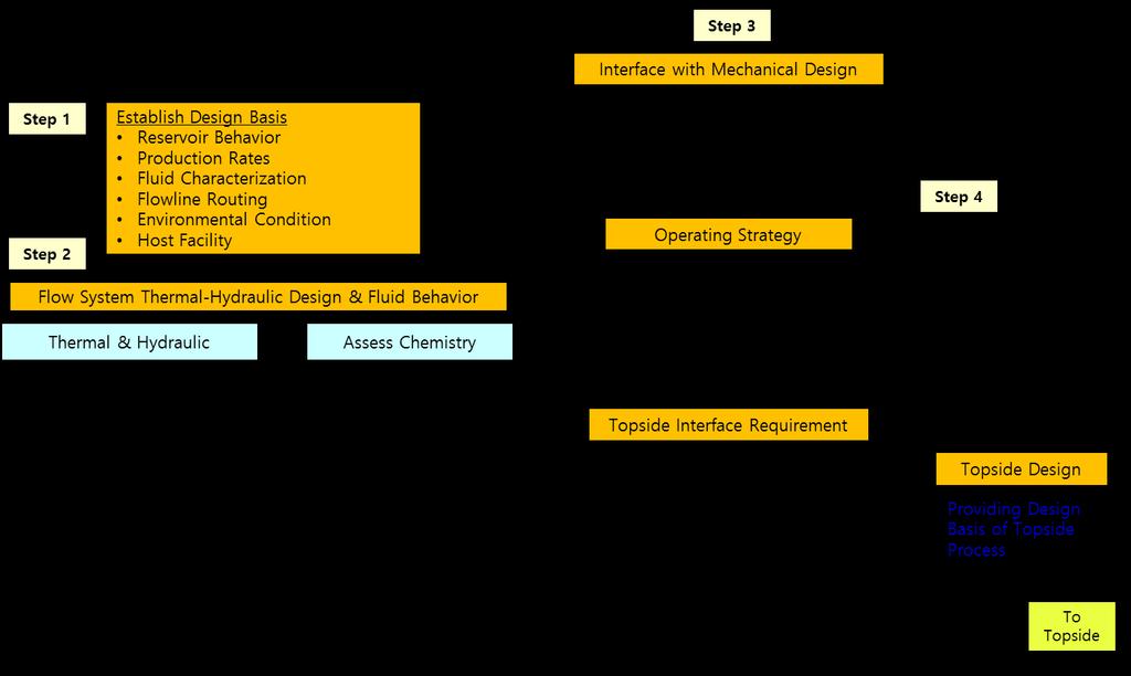
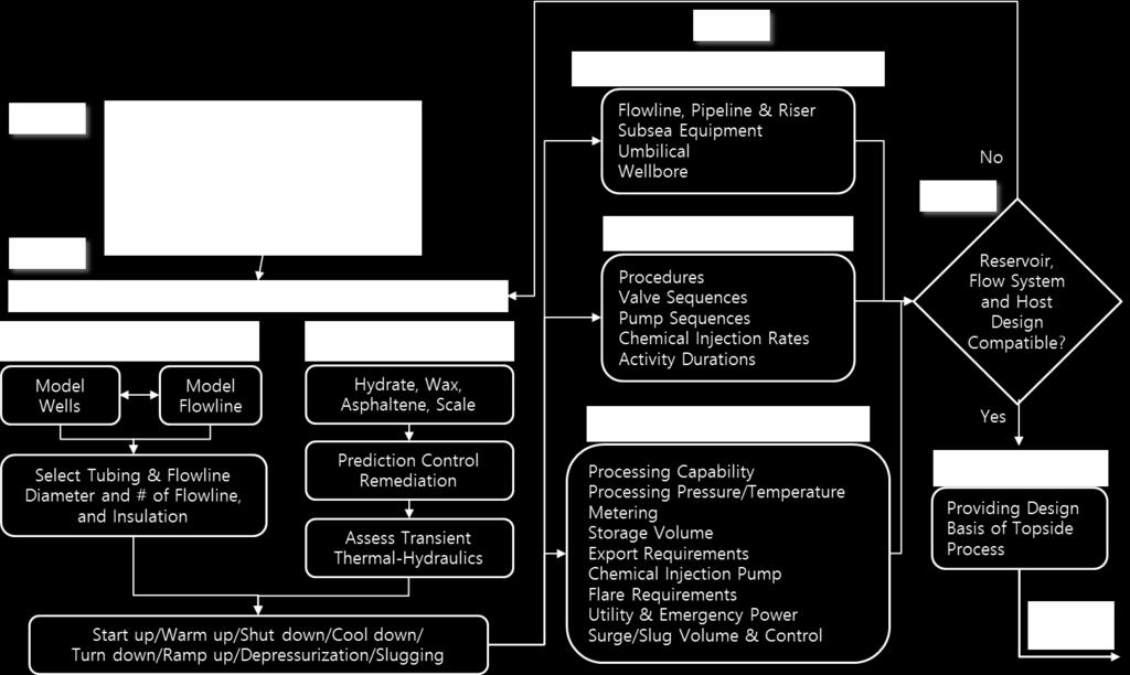
27 Stage 1. Review and finalize design basis 1. Generally, the system is assumed to comprise of flowlines, risers, umbilicals, wellbore, jumpers, manifolds, PLETs, and CPFs. 2. Fluid product obtained from a reservoir is transported to CPF via wellbores, flowlines, and risers. Various chemicals and electricity are transferred from CPF to the subsea through umbilicals. 3. The following input resources are required to run a simulation based on the system explained above: : Field scheme (platform type, size and location of equipment) : Reservoir compositions, pipeline property (pipeline geometry, pipeline diameter / material / thickness, insulation material / thickness) : Environmental conditions (air temperature / velocity, water temperature / velocity) : Boundary conditions (reservoir conditions, topside arrival conditions) 4. Fluid characterization should be included in this step, and relevant materials are described in Note 1.
28 Stage 2. Thermodynamic design and fluid behavior Steady-state analysis 1. Carry out a thermal & hydraulics analysis by using steady-state simulation to obtain fluid temperature, pressure, flow rate, flow velocity, and liquid hold up profile of the pipeline fluid. 2. Calculate inner diameter of the pipeline using the results. 3. Determine specifications for a pump or a compressor for use in topside or subsea. Shutdown analysis 1. Carry out a ramp down analysis prior to the shutdown simulation to obtain the minimum slug free flow rate. Plan a ramp down scenario accordingly, and then proceed. 2. Locate potential regions for hydrate formation using DTHYD in order to analyze the hydrate risk using the shutdown simulation. Assume cool down time as the time span when the temperature is above 0 C on DTHYD. Find the temperature region where hydrate formation is at high risk by observing the water hold up, simultaneously. 3. WAT (Was Arrival Temperature) is used to check whether or not wax deposition has taken place. It is possible to calculate the time taken for fluid to reach the gel point or WAT during the shutdown operation. 4. If dead oil displacement carried out, it is possible to calculate the dead oil volume and injection pressure.
29 Start-up analysis 1. Analyze the flow regime by carrying out thermal & hydraulic analysis and identify whether slugging occurs or not. Calculate maximum surge volume by surge analysis and determine the size of surge tanks. 2. In case of a cold restart, warm-up time can be calculated. Warm-up time is when the temperature is below 0 C on DTHYD. Additional 3 C on DTHYD can be regarded as an engineering margin. Figure out the amount of hydrate inhibitor based on the warm-up time obtained. 3. Be cautious of hydrate, wax, or any other solid deposition during the cold restart. 4. Keep an eye out for the DTHYD variables during OLGA simulation. Pigging analysis 1. Both mechanical pigging and injection of chemical inhibitors are required in removing pipeline debris. 2. Estimate the amount of accumulated wax for effective pigging operation. Calculate the pigging frequency using this. Calculate the outlet pressure while pigging, and predict the flow regime of the pipeline and its maximum surge volume. 3. Note the following variables during OLGA simulation: ID (flow regime), SURGELIQ (surge liquid volume).
30 Depressurization of flowlines : If depressurization occurs between shutdown and startup, it is possible to calculate the maximum liquid / gas rate, minimum temperate, depressurization time during the blow down by depressurization analysis. Remediation strategy set-up : An appropriate remediation method characterized by each fields is needed in the event of hydrate, wax, or any other solid depositions. Refer to Note 2 for detailed remediation management strategies. Information related to hydrates is shown in Note 3. Corrosion / erosion analysis : Corrosion can occur inside or outside the pipeline. Internal carrion can be divided into sweet and sour corrosion according to the differing composition of CO 2 and H 2 S. Sand deposition analysis : Sand flowing in from the reservoir causes erosion and this directly affects the production rate. It is possible to lengthen lifetime of field production and ensure stable production by an appropriate sand management.
31 Stage 3 : Based on the obtained thermal/hydraulic analysis results in stage 2, the design of offshore and topside production systems can be performed using the company s internal design guideline : Line sizing flowline, riser, jumper, spool, umbilical. : Vessel sizing slug catcher, separator, reflux drum, gas and oil processing units, condensate storage tank, inhibitor storage tank. : Pressure rating pressure safety valves, pumps, compressors : Operation philosophy valve opening/closing, pump sequences for injection and export, chemical injection, Stage 4 : Following the company s internal design guideline, verify the design and operation philosophy of offshore and topside production systems
32 Note 1. Fluid characterization
33 Note 2. Multiphase flow simulation
34 Note 3. Hydrate prevention
35 Summary Multiphase flow and solid deposition issues can be faced for the development of offshore oil and gas fields. Each issue has its own characteristic and needs special care to avoid unwanted outcomes such as production stoppage. The complex relationship between the flow assurance issues even make the problem worse, thus reliable work process is required. The flow assurance work process is composed of i) fluid characterization, ii) thermal/hydraulic analysis, iii) solid deposition analysis, and iv) production system design. The work process provide detailed approach to conduct flow assurance study for target offshore field by incorporating multiphase flow simulation with OLGA. It will provide an insight to field engineers to design and operation of their production system
36 Thank you
Dynamic Simulation Content. be dynamic
 Dynamic Simulation Content 1. Dynamic Simulation 2. Dynamic Simulation in Gas Lift Systems ALRDC 2005 Spring GAS LIFT WORSHOP Rio de Janeiro Brazil 21-25 February be dynamic www.scandpowerpt.com by Juan
Gas Lift Workshop Doha Qatar 4-88 February Gas Lift Optimisation of Long Horizontal Wells. by Juan Carlos Mantecon
 Gas Lift Workshop Doha Qatar 4-88 February 2007 Gas Lift Optimisation of Long Horizontal Wells by Juan Carlos Mantecon 1 Long Horizontal Wells The flow behavior of long horizontal wells is similar to pipelines
Pigging as a Flow Assurance Solution Avoiding Slug Catcher Overflow
 Pigging as a Flow Assurance Solution Avoiding Slug Catcher Overflow Aidan O'Donoghue, Pipeline Research Limited, Glasgow, UK This paper sets out to provide an initial method of assessing the bypass requirements
Gas Injection for Hydrodynamic Slug Control
 Proceedings of the IFAC Workshop on Automatic Control in Offshore Oil and Gas Production, Norwegian University of Science and Technology, Trondheim, Norway, May 3 - June, ThB.4 Gas Injection for Hydrodynamic
Flow transients in multiphase pipelines
 Flow transients in multiphase pipelines David Wiszniewski School of Mechanical Engineering, University of Western Australia Prof. Ole Jørgen Nydal Multiphase Flow Laboratory, Norwegian University of Science
Pipeline Flooding, Dewatering and Venting Dr Aidan O'Donoghue, Pipeline Research Limited, Glasgow, Scotland
 Pipeline Flooding, Dewatering and Venting Dr Aidan O'Donoghue, Pipeline Research Limited, Glasgow, Scotland Abstract Flooding, cleaning, gauging, dewatering and venting of offshore oil and gas pipelines
Tutorial. BOSfluids. Relief valve
 Tutorial Relief valve The Relief valve tutorial describes the theory and modeling process of a pressure relief valve or safety valve. It covers the algorithm BOSfluids uses to model the valve and a worked
PIG MOTION AND DYNAMICS IN COMPLEX GAS NETWORKS. Dr Aidan O Donoghue, Pipeline Research Limited, Glasgow
 PIG MOTION AND DYNAMICS IN COMPLEX GAS NETWORKS Dr Aidan O Donoghue, Pipeline Research Limited, Glasgow A model to examine pigging and inspection of gas networks with multiple pipelines, connections and
Yutaek Seo. Subsea Engineering
 Yutaek Seo Subsea Engineering Inlet receiving Gas and liquids that enter the gas processing facilities pass emergency shutdown valves, and then go to inlet receiving, where condensed phases drop out. Gas
Hydraulics analysis of the Heidrun offshore field
 Hydraulics analysis of the Heidrun offshore field P.Andreussi & E. Sangnes University of Pisa, Italy M. Bonizzi TEA Sistemi, Italy M. Nordsveen, E. Sletfjerding &, I. Berg Martiniussen Statoil ASA, Norway
GAS LIFT IN NEW FIELDS
 GAS LIFT IN NEW FIELDS GAS LIFT in NEW FIELDS NEW DESIGN FOR WELLS AND COMPRESSORS RESERVOIR AND PRODUCTION SIMULATION MATCHING REQUIRED PRODUCTION NODAL ANALYSIS SIMULATION USED TO SELECT INJECTION DEPTH
Caltec. The world leader in Surface Jet Pump (SJP) and compact separation systems for upstream oil and gas production enhancement
 and compact separation systems for upstream oil and gas production enhancement") Caltec brings simple passive technology that enables oil and gas operators to harness the kinetic energy of the production process to enhance their production, extending economic field life and reducing
Caltec brings simple passive technology that enables oil and gas operators to harness the kinetic energy of the production process to enhance their production, extending economic field life and reducing
Department of Offshore, Process Systems and Energy Engineering. Cranfield University, MK43 0AL, Bedfordshire, England, United Kingdom
 International Journal of Advancements in Research & Technology, Volume 2, Issue 10, October-2013 178 SMART CONTROL OF HYDRODYNAMIC SLUG FLOW Inyiama, Fidelis Chidozie; e-mail: < f.c.inyiama@cranfield.ac.uk>
Transient Analyses In Relief Systems
 Transient Analyses In Relief Systems Dirk Deboer, Brady Haneman and Quoc-Khanh Tran Kaiser Engineers Pty Ltd ABSTRACT Analyses of pressure relief systems are concerned with transient process disturbances
BRINGING A NEW DIMENSION TO PIPELINE PIGGING. By: David Aitken, Aubin Group, UK
 BRINGING A NEW DIMENSION TO PIPELINE PIGGING By: David Aitken, Aubin Group, UK The importance of keeping pipework clear of restrictions and debris to allow maximum flow conditions cannot be emphasised
STUDY OF SLUG CONTROL TECHNIQUES IN PIPELINE SYSTEMS
 STUDY OF SLUG CONTROL TECHNIQUES IN PIPELINE SYSTEMS JOSÉ L. A,VIDAL Petrobrás Research Center - CENPES/PDEP/TOOL Av.Horácio de Macedo 95- Cidade Universitária 191-915 -Rio de Janeiro-RJ E-mail:josearias@petrobras.com.br
Drilling Efficiency Utilizing Coriolis Flow Technology
 Session 12: Drilling Efficiency Utilizing Coriolis Flow Technology Clement Cabanayan Emerson Process Management Abstract Continuous, accurate and reliable measurement of drilling fluid volumes and densities
The Use of Subsea Gas-Lift in Deepwater Applications. Subash Jayawardena, George Zabaras, and Leonid Dykhno Shell Global Solutions (US) Inc.
 Inc.") The Use of Subsea Gas-Lift in Deepwater Applications Subash Jayawardena, George Zabaras, and Leonid Dykhno Shell Global Solutions (US) Inc. Contents Why Gas-Lift is Needed Gas Lift Delivery System Design
The Use of Subsea Gas-Lift in Deepwater Applications Subash Jayawardena, George Zabaras, and Leonid Dykhno Shell Global Solutions (US) Inc. Contents Why Gas-Lift is Needed Gas Lift Delivery System Design
Gas Vapor Injection on Refrigerant Cycle Using Piston Technology
 Purdue University Purdue e-pubs International Refrigeration and Air Conditioning Conference School of Mechanical Engineering 2012 Gas Vapor Injection on Refrigerant Cycle Using Piston Technology Sophie
DISTILLATION POINTS TO REMEMBER
 DISTILLATION POINTS TO REMEMBER 1. Distillation columns carry out physical separation of liquid chemical components from a mixture by a. A combination of transfer of heat energy (to vaporize lighter components)
Aspen HYSYS. Dynamic Modeling Guide
 Aspen HYSYS Dynamic Modeling Guide Version Number: V7.3 March 2011 Copyright (c) 1981-2011 by Aspen Technology, Inc. All rights reserved. Aspen HYSYS and the aspen leaf logo are trademarks or registered
PETROLEUM & GAS PROCESSING TECHNOLOGY (PTT 365) SEPARATION OF PRODUCED FLUID
 SEPARATION OF PRODUCED FLUID") PETROLEUM & GAS PROCESSING TECHNOLOGY (PTT 365) SEPARATION OF PRODUCED FLUID Miss Nur Izzati Bte Iberahim Introduction Well effluents flowing from producing wells come out in two phases: vapor and liquid
PETROLEUM & GAS PROCESSING TECHNOLOGY (PTT 365) SEPARATION OF PRODUCED FLUID Miss Nur Izzati Bte Iberahim Introduction Well effluents flowing from producing wells come out in two phases: vapor and liquid
Section 2 Multiphase Flow, Flowing Well Performance
 Section 2 Multiphase Flow, Flowing Well Performance Multiphase Vertical Flow When producing an oil or gas well, the flow of the fluids up the tubing will be in most cases be 2 phase, liquid and gas. The
Steam generator tube rupture analysis using dynamic simulation
 Steam generator tube rupture analysis using dynamic simulation Heat Exchangers are used to transfer heat from a hot fluid to a cold fluid. Most of the times these fluids are available at different pressures
LOW PRESSURE EFFUSION OF GASES revised by Igor Bolotin 03/05/12
 LOW PRESSURE EFFUSION OF GASES revised by Igor Bolotin 03/05/ This experiment will introduce you to the kinetic properties of low-pressure gases. You will make observations on the rates with which selected
LOW PRESSURE EFFUSION OF GASES adapted by Luke Hanley and Mike Trenary
 ADH 1/7/014 LOW PRESSURE EFFUSION OF GASES adapted by Luke Hanley and Mike Trenary This experiment will introduce you to the kinetic properties of low-pressure gases. You will make observations on the
17J Third Edition, January 2008 Specification for Unbonded Flexible Pipe
 API Specification 17J Third Edition, January 2008 National Adoption of ISO 13628:2006(Identical) Petroleum and natural gas industries Design and operation of subsea production systems Part 2: Unbonded
Injector Dynamics Assumptions and their Impact on Predicting Cavitation and Performance
 Injector Dynamics Assumptions and their Impact on Predicting Cavitation and Performance Frank Husmeier, Cummins Fuel Systems Presented by Laz Foley, ANSYS Outline Overview Computational Domain and Boundary
Joint industry project on foam
 Joint industry project on foam, E.D. Nennie (TNO Fluid dynamics) W. Schiferli (Shell Projects & Technology) 2 Introduction Foamers are used for gas well deliquification. Lab tests are being used to evaluate
Workshop 1: Bubbly Flow in a Rectangular Bubble Column. Multiphase Flow Modeling In ANSYS CFX Release ANSYS, Inc. WS1-1 Release 14.
 Workshop 1: Bubbly Flow in a Rectangular Bubble Column 14. 5 Release Multiphase Flow Modeling In ANSYS CFX 2013 ANSYS, Inc. WS1-1 Release 14.5 Introduction This workshop models the dispersion of air bubbles
Tirpur Area Water Supply Project A Report on Transient Modeling Study
 y February 2008 1 of 81 y INTRODUCTION: The report presents results from a transient modeling study conducted on the clear water transmission main of Tirpur Areas Water Supply Project, Tamilnadu, India.
Flow Assurance Study
 Available online at www.sciencedirect.com Energy Procedia 37 (213 ) 318 33 GHGT-11 Flow Assurance Study Wolfgang Böser a,b *, Stefan Belfroid c a ROAD Maasvlakte CCS Project C.V., NL 3112 NA Schiedam,
THE CSIRO S HYDRATES FLOW LOOP AS A TOOL TO INVESTIGATE HYDRATE BEHAVIOUR IN GAS DOMINANT FLOWS
 Proceedings of the 7th International Conference on Gas Hydrates (ICGH ), Edinburgh, Scotland, United Kingdom, July 7-,. THE CSIRO S HYDRATES FLOW LOOP AS A TOOL TO INVESTIGATE HYDRATE BEHAVIOUR IN GAS
Dynamic Simulation of the Norne Heidrun 10 x 16 Dewatering Pig
 Dynamic Simulation of the Norne Heidrun 10 x 16 Dewatering Pig Aidan O'Donoghue, Pipeline Research Limited, Glasgow, UK ( contact@pipeline-research.com, www.pipeline-research.com ) Introduction The 10
Gerald D. Anderson. Education Technical Specialist
 Gerald D. Anderson Education Technical Specialist The factors which influence selection of equipment for a liquid level control loop interact significantly. Analyses of these factors and their interactions
Faculty of Natural Sciences and Technology MASTER THESIS 2010
 NTNU Norwegian University of Science and Technology Faculty of Natural Sciences and Technology Department of Chemical Engineering MASTER THESIS 2010 Title: Stabilization of two-phase flow in risers from
NEW VERSAFLOW CORIOLIS
 Steffen Baecker June 20, 2017 NEW VERSAFLOW CORIOLIS With Stable Two-phase Flow Measurement Honeywell Internal VersaFlow Flow Technologies Volume flow measurement Conductive fluids only - Water - Chemicals
SPE Active Feedback Control as the Solution to Severe Slugging Kjetil Havre 1, ABB Corporate Research, and Morten Dalsmo, SPE, ABB
 SPE 7154 Active Feedback Control as the Solution to Severe Slugging Kjetil Havre 1, ABB Corporate Research, and Morten Dalsmo, SPE, ABB Copyright 21, Society of Petroleum Engineers Inc. This paper was
SPE The paper gives a brief description and the experience gained with WRIPS applied to water injection wells. The main
 SPE 102831 Online Water-Injection Optimization and Prevention of Reservoir Damage Bjørn Øyvind Bringedal, Svein Arne Morud, Nicolas Alexander Hall, ABB; Gary Huseman, Shell Copyright 2006, Society of Petroleum
Courses of Instruction: Controlling and Monitoring of Pipelines
 Courses of Instruction: Controlling and Monitoring of Pipelines Date December 2010 Dr. Peter Eschenbacher Partner Angergraben 4 85250 Altomünster Germany Tel. +49-(0)8254 / 99 69 57 Fax +49-(0)8254 / 99
Platelets & Plasma The Management of Unplanned Flow
 Platelets & Plasma The Management of Unplanned Flow Who are Brinker? Managing Unplanned Flo Range of innovative products & specialist services to enable operators to effectively manage unplanned flow events
Numerical Analysis of Two Phase Flow Patterns in Vertical and Horizontal Pipes
 Numerical Analysis of Two Phase Flow Patterns in Vertical and Horizontal Pipes MOHAMMED A. ABDULWAHID, HASANAIN J. KAREEM, MUJTABA A. ALMUDHAFFAR Thermal Mechanical Engineering, Southern Technical University,
REFERENCE GUIDE. Rev. 0 15/09/2016
 VALVE SIZING CALCULATOR REFERENCE GUIDE Rev. 0 15/09/2016 Copyright HIT VALVE S.p.A. 2016 All rights reserved. No part of this publication may be reproduced, stored in a retrieval system, or transmitted,
PRESSURE SURGES IN PIPELINES
 CHAPTER 4 PRESSURE SURGES IN PIPELINES 4.1 FEATURES OF PRESSURE SURGE In the past, water engineers were facing problems with repeated pipe bursts, failing seals etc. They termed the cause of failure as
I. CHEM. E. SYMPOSIUM SERIES NO. 85
 FIRE SURVIVAL OF PROCESS VESSELS CONTAINING GAS J. Nylund * The present work is a theoretical evaluation of the ability of process vessels to survive hydrocarbon fires when the vessels are designed and
LP Separator Level Control by Variable Speed and Multi Stage Brine Reinjection Pumps at Kawerau and Nga Awa Purua Geothermal Projects, New Zealand
 Proceedings World Geothermal Congress 2010 Bali, Indonesia, 25-29 April 2010 LP Separator Level Control by Variable Speed and Multi Stage Brine Reinjection Pumps at Kawerau and Nga Awa Purua Geothermal
Evaluation of a Flow Simulator for Multiphase Pipelines
 Evaluation of a Flow Simulator for Multiphase Pipelines Jeppe Mathias Jansen Master of Science in Energy and Environment Submission date: June 2009 Supervisor: Ole Jørgen Nydal, EPT Co-supervisor: Kjartan
Environmental Science: An Indian Journal
 Environmental Science: An Indian Journal Research Vol 14 Iss 1 Flow Pattern and Liquid Holdup Prediction in Multiphase Flow by Machine Learning Approach Chandrasekaran S *, Kumar S Petroleum Engineering
Computer Simulation Helps Improve Vertical Column Induced Gas Flotation (IGF) System
 System") JOURNAL ARTICLES BY FLUENT SOFTWARE USERS JA187 Computer Simulation Helps Improve Vertical Column Induced Gas Flotation (IGF) System Computer simulation has helped NATCO engineers make dramatic improvements
JOURNAL ARTICLES BY FLUENT SOFTWARE USERS JA187 Computer Simulation Helps Improve Vertical Column Induced Gas Flotation (IGF) System Computer simulation has helped NATCO engineers make dramatic improvements
Tube rupture in a natural gas heater
 Tube rupture in a natural gas heater Dynamic simulation supports the use of a pressure safety valve over a rupture disk in the event of a tube rupture HARRY Z HA and PATRICK STANG Fluor Canada Ltd A fast
Multiphase MixMeter. MixMeter specification. System Specification. Introduction
 System Specification Multiphase MixMeter Introduction The MixMeter is unique in applying proper homogenization techniques to multiphase measurement. In so doing the MixMeter avoids the requirement for
W I L D W E L L C O N T R O L FLUIDS
 FLUIDS Fluids Learning Objectives You will learn about different fluids that can be used in well control. You will become familiar with the characteristics and limitations of fluids. You will learn general
A review of best practices for Selection, Installation, Operation and Maintenance of Gas meters for Flare Applications used for Managing facility
 A review of best practices for Selection, Installation, Operation and Maintenance of Gas meters for Flare Applications used for Managing facility mass balance and compliance 1. What, When and Why? 2. Flare
Evaluation of Hydropath Clearwell Technology On Carbonate Brine Scaling Using Tube Blocking Method
 Flow Assurance R-4-319 November 24 Evaluation of Hydropath Clearwell Technology On Carbonate Brine Scaling Using Tube Blocking Method Final Report Authors: S. Brown & J. Rohan Work By: J. Rohan Westport
2 FUSION FITTINGS FOR USE WITH POLYETHYLENE PRESSURE PIPES DESIGN FOR DYNAMIC STRESSES
 Industry Guidelines Part 2 FUSION FITTINGS FOR USE WITH POLYETHYLENE PRESSURE PIPES DESIGN FOR DYNAMIC STRESSES ISSUE 5.1 Ref: POP10B 15 MAR 2010 Disclaimer In formulating this guideline PIPA has relied
A Computational Assessment of Gas Jets in a Bubbly Co-Flow 1
 A Computational Assessment of Gas Jets in a Bubbly Co-Flow 1 Melissa Fronzeo*, 1 Michael Kinzel 1 The Pennsylvania State University, University Park, PA, USA Abstract In this effort, Computational Fluid
Review of Source Term Modelling for Hydrocarbon Releases using Process Dynamic Simulation
 Review of Source Term Modelling for Hydrocarbon Releases using Process Dynamic Simulation Conor Crowley and Mrudhul Raj, Atkins Limited, Kirkgate House, Upperkirkgate, Aberdeen AB10 1HW Andrew Ross, Chemical
OLGA Modeling Results for Single Well Reinjection of Non-Condensable Gases (NCGs) and Water
 and Water") GRC Transactions, Vol. 4, 216 OLGA Modeling Results for Single Well Reinjection of Non-Condensable Gases (NCGs) and Water R. W. Stacey, 1 L. Norris, 2 and S. Lisi 3 1 GeothermEx, Richmond CA, USA 2 Schlumberger
GRC Transactions, Vol. 4, 216 OLGA Modeling Results for Single Well Reinjection of Non-Condensable Gases (NCGs) and Water R. W. Stacey, 1 L. Norris, 2 and S. Lisi 3 1 GeothermEx, Richmond CA, USA 2 Schlumberger
Two phase discharge flow prediction in safety valves
 Dempster W, Elmayyah W/ ICPVT-13 1 Two phase discharge flow prediction in safety valves William Dempster a, Wael Elmayyah b a Department of Mechanical and Aerospace Engineering, University of Strathclyde,
SUPERSONIC GAS TECHNOLOGIES
 SUPERSONIC GAS TECHNOLOGIES Vladimir Feygin, Salavat Imayev, Vadim Alfyorov, Lev Bagirov, Leonard Dmitriev, John Lacey TransLang Technologies Ltd., Calgary, Canada 1. INTRODUCTION The 3S technology is
Suppress Your Surges: Surge Suppression Fundamentals. April 13, 2017
 Suppress Your Surges: Surge Suppression Fundamentals April 13, 2017 How Bad Can Waterhammer Really Be? 2 Workshop Agenda What is waterhammer? Causes of waterhammer Instantaneous surge pressures Surges
Experiment 8: Minor Losses
 Experiment 8: Minor Losses Purpose: To determine the loss factors for flow through a range of pipe fittings including bends, a contraction, an enlargement and a gate-valve. Introduction: Energy losses
Compressors. Basic Classification and design overview
 Compressors Basic Classification and design overview What are compressors? Compressors are mechanical devices that compresses gases. It is widely used in industries and has various applications How they
The Discussion of this exercise covers the following points: Range with an elevated or suppressed zero Suppressed-zero range Elevated-zero range
 Exercise 4-3 Zero Suppression and Zero Elevation EXERCISE OBJECTIVE In this exercise, you will learn the effect that mounting a pressure transmitter above or below the reference level has on the hydrostatic
CVEN 311 Fluid Dynamics Fall Semester 2011 Dr. Kelly Brumbelow, Texas A&M University. Final Exam
 CVEN 311 Fluid Dynamics Fall Semester 2011 Dr. Kelly Brumbelow, Texas A&M University Final Exam 8 pages, front & back, not including reference sheets; 21 questions An excerpt from the NCEES Fundamentals
TABLE OF CONTENT
 Page : 1 of 22 Project Engineering Standard www.klmtechgroup.com KLM Technology #03-12 Block Aronia, Jalan Sri Perkasa 2 Taman Tampoi Utama 81200 Johor Bahru Malaysia S) TABLE OF CONTENT SCOPE 2 VESSELS
ME 200 Thermodynamics I Spring 2010 (Last) (First) Thermo Number: CIRCLE YOUR LECTURE BELOW
 (First) Thermo Number: CIRCLE YOUR LECTURE BELOW") ME 200 Thermodynamics I Name: Spring 2010 Thermo Number: CIRCLE YOUR LECTURE BELOW Div. 1 8:30 am Div. 2 10:30 am Div. 3 12:30 pm Naik Tree Clark Div. 4 1:30 pm Kim Div. 5 3:30 pm Mathison EXAM 2 INSTRUCTIONS
ME 200 Thermodynamics I Name: Spring 2010 Thermo Number: CIRCLE YOUR LECTURE BELOW Div. 1 8:30 am Div. 2 10:30 am Div. 3 12:30 pm Naik Tree Clark Div. 4 1:30 pm Kim Div. 5 3:30 pm Mathison EXAM 2 INSTRUCTIONS
S-CO 2 Brayton Recompression Loop Design and Control
 S-CO 2 Brayton Recompression Loop Design and Control 1) Background 2) Recommended Design Features 3) Modeling Strategy IST Model Changes Transient Results Prepared by: Mike Hexemer Advanced Concepts Knolls
Offshore Equipment. Yutaek Seo
 Offshore Equipment Yutaek Seo Flash Gas Compressor (East spar) Dehydration NGL recovery Slug catcher Separator Stabilization Booster compressor Gas export compression (Donghae-1 Platform) May 7 th Gas
Faculty of Science and Technology MASTER S THESIS. Writer: Rune Kvammen
 Faculty of Science and Technology MASTER S THESIS Study program/ Specialization: Petroleum Engineering / Production technology Spring semester, 2011 Open access Writer: (Writer s signature) Faculty supervisor:
Effect of 180 bends on gas/liquid flows in vertical upward and downward pipes
 Computational Methods in Multiphase Flow VII 435 Effect of 180 bends on gas/liquid flows in vertical upward and downward pipes A. Almabrok, L. Lao & H. Yeung Department of Offshore, Process and Energy
Active Hydrophore System AHS-01
 BRIEF PRODUCT DESCRIPTION: Standard material Seawater exposed parts: Titanium gr. 2 Rapid Response Valves: Titanium gr. 2 Cabinet: SST AISI 316 This is a skid mounted unit, with the hydrophore tank and
Irrigation &Hydraulics Department lb / ft to kg/lit.
 CAIRO UNIVERSITY FLUID MECHANICS Faculty of Engineering nd Year CIVIL ENG. Irrigation &Hydraulics Department 010-011 1. FLUID PROPERTIES 1. Identify the dimensions and units for the following engineering
Low Coking Temperatures & Recent Site Experience
 Delayed Coker Low Coking Temperatures & Recent Site Experience Presented by Mitch Moloney of ExxonMobil mitchell.j.moloney@exxonmobil.com @ Coking.com April-2010 MJ a Moloney - ExxonMobil April-2010 coking.com
Slug Catchers Engineered Solutions to Separation Problems
 Slug Catchers Engineered Solutions to Separation Problems Separation Products from Taylor Forge Taylor Forge Engineered Systems has been a leading manufacturer of liquid separation equipment for the pipeline
API th Edition Ballot Item 7.8 Work Item 4 Gas Breakthrough
 API 521 7 th Edition Ballot Item 7.8 Work Item 4 Gas Breakthrough NOTE: This is a reballot of previously approved API 521 7 th Edition Ballot Item 6.3 which was modified based on comments. Comments should
Modelling of the Separated Geothermal Water Flow between Te Mihi flash plants
 Proceedings World Geothermal Congress 2015 Melbourne, Australia, 19-25 April 2015 Modelling of the Separated Geothermal Water Flow between Te Mihi flash plants Kevin Koorey, Kim Harwood and Norman Lawgun
MULTI-DIAMETER, BI-DIRECTIONAL PIGGING FOR PIPELINE PRE-COMMISSIONING
 MULTI-DIAMETER, BI-DIRECTIONAL PIGGING FOR PIPELINE PRE-COMMISSIONING By: Magne Andreas Vik, StatoilHydro; Alf Åge Kristiansen, StatoilHydro Simon Sykes, FTL Seals Technology; Steve Hutcheson, Pipeline
PRODUCTION AND OPERATIONAL ISSUES
 PRODUCTION AND OPERATIONAL ISSUES Dr. Ebrahim Fathi Petroleum and Natural Gas Engineering Department West Virginia University Audience and Date March 2, 2016 Summary Production and Operational Issues Shale
OIL AND GAS INDUSTRY
 This case study discusses the sizing of a coalescer filter and demonstrates its fouling life cycle analysis using a Flownex model which implements two new pressure loss components: - A rated pressure loss
Chapter 8: Reservoir Mechanics
 PTRT 1472: Petroleum Data Management II Chapter 8: Reservoir Mechanics - Reservoir drives Types of Natural Gas Reservoir Fluids Natural gas is petroleum in a gaseous state, so it is always accompanied
A Successful Experience in Optimization of a Production Well in a Southern Iranian Oil Field
 Iranian Journal of Chemical Engineering Vol. 6, No. 2 (Spring), 2009, IAChE A Successful Experience in Optimization of a Production Well in a Southern Iranian Oil Field S. R. Shadizadeh, M. Zoveidavianpoor
Performance Characteristics of Airlift Pumps with Vortex Induced by Tangential Fluid Injection
 Bucknell University Bucknell Digital Commons Honors Theses Student Theses 2011 Performance Characteristics of Airlift Pumps with Vortex Induced by Tangential Fluid Injection Jacob Riglin Bucknell University
EDUCTOR. principle of operation
 EDUCTOR principle of operation condensate and mixing eductor s are designed to mix two liquids intimately in various proportions in operations where the pressure liquid is the greater proportion of the
CFD and Physical Modeling of DSI/ACI Distribution
 CFD and Physical Modeling of DSI/ACI Distribution APC Round Table & Exposition July 09, 2013 Matt Gentry mgentry@airflowsciences.com 734-525-0300 1 Outline Introduction Flow Analysis Techniques Application
Carbon Dioxide Flooding. Dr. Helmy Sayyouh Petroleum Engineering Cairo University
 Carbon Dioxide Flooding Dr. Helmy Sayyouh Petroleum Engineering Cairo University Properties of CO 2... Properties of CO2... CO2 density increases with:.increasing pressure.decreasing temperature Viscosity
Dilution-Based Dual Gradient Well Control. Presented at the 2011 IADC Dual Gradient Workshop, 5 May 2011 by Paul Boudreau, Dual Gradient Systems LLC
 Dilution-Based Dual Gradient Well Control Presented at the 2011 IADC Dual Gradient Workshop, 5 May 2011 by Paul Boudreau, Dual Gradient Systems LLC In this very short presentation, we will Review Dilution-based
An Impeller Blade Analysis of Centrifugal Gas Compressor Using CFD
 An Impeller Blade Analysis of Centrifugal Gas Compressor Using CFD Vivek V. Kulkarni Department of Mechanical Engineering KLS Gogte Institute of Technology, Belagavi, Karnataka Dr. Anil T.R. Department
POP Safety Valve. POP Safety Valve INTRODUCTION DEFINITIONS
 POP Safety Valve POP Safety Valve INTRODUCTION The effects of exceeding safe pressure levels in an unprotected pressure vessel or system, can have catastrophic effects on both plant and personnel. Safety
Oil And Gas Office Houston Fax Test Separator / Off-Shore Metering
 Oil And Gas Office Houston 281 361 0708 Fax 201 361 0708 Test Separator / Off-Shore Metering Prepared By : Mr. Phil Lawrence A. M. Inst Mech E. Sales Manager (Oil and Gas Industry) 2.0 Philosophy for Test
PC-PUMP Points to Consider
 PC-PUMP Points to Consider March 2007 This document contains a list of details regarding the use of C-FER s PC-PUMP software that all users should be aware of. These are based on questions asked and problems
NORMAL OPERATING PROCEDURES Operating Parameter Information
 Operating Parameter Information Each operator performing the normal operating procedures (routine checks) of the facility should be familiar with the current normal operating parameters of all systems
Numerical simulation of the ALBA s synchrotron cooling system response to pump start-up and shut-down Page 1
 Numerical simulation of the ALBA s synchrotron cooling system response to pump start-up and shut-down Page 1 Abstract This project consists of the development and validation of a numerical model to simulate
KICK CIRCULATION ANALYSIS FOR EXTENDED-REACH AND HORIZONTAL WELLS. A Thesis MAXIMILIAN M. LONG
 KICK CIRCULATION ANALYSIS FOR EXTENDED-REACH AND HORIZONTAL WELLS A Thesis by MAXIMILIAN M. LONG Submitted to the Office of Graduate Studies of Texas A&M University in partial fulfillment of the requirements
Numerical Simulations of a Train of Air Bubbles Rising Through Stagnant Water
 Numerical Simulations of a Train of Air Bubbles Rising Through Stagnant Water Hong Xu, Chokri Guetari ANSYS INC. Abstract Transient numerical simulations of the rise of a train of gas bubbles in a liquid
UNIQUE ADVANTAGES OF PIPENET
 UNIQUE ADVANTAGES OF PIPENET TRANSIENT MODULE Sunrise Systems Limited Section 1: Unique Advantages of the leading hydraulic analysis software engineers prefer to use: PIPENET s schematic design is unique.
NEW SUBSEA PROCESS COOLER; PART I: FOCUSED ON FLOW ASSURANCE, OPERATION AND RELIABILITY
 NEW SUBSEA PROCESS COOLER; PART I: FOCUSED ON FLOW ASSURANCE, OPERATION AND RELIABILITY Stig Kanstad, Julien Rolland, Vivian Lyngvaer Framo Engineering, a Schlumberger Company, Caroline Boe, Henning Bodtker
Subsea Safety Systems
 Subsea Safety Systems The ELSA-HP has been developed to service the high pressure horizontal tree completion and intervention market. With systems designed and qualified up to 15,000 psi, 250 degf and
Fundamentals Of Petroleum Engineering PRODUCTION
 Fundamentals Of Petroleum Engineering PRODUCTION Mohd Fauzi Hamid Wan Rosli Wan Sulaiman Department of Petroleum Engineering Faculty of Petroleum & Renewable Engineering Universiti Technologi Malaysia
Challenges in Relief Design for Pilot Plants
 Challenges in Relief Design for Pilot Plants Published on July 5, 2017 Michael Trainor Relief system design at the pilot scale presents unique challenges that don t always apply at the commercial scale.