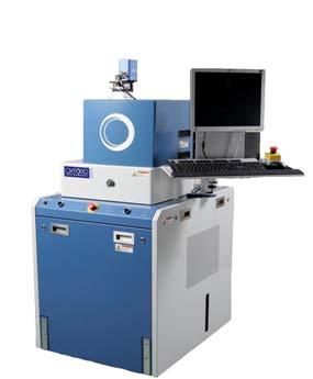
Oxford Instruments Plasma Technology. PlasmaPro NGP80. Installation Data Sheet. Original Instructions.
|
|
|
- Laurel McCarthy
- 5 years ago
- Views:
Transcription


1 Oxford Instruments Plasma Technology
2 About this data sheet This data sheet provides basic information about the installation of a tool. Floor and wall loadings Table 1 lists typical weights of system components. Ensure that the floor is rated to support the weight of the main frame, the backing pump and the heater/chiller (if provided). Ensure that the wall is rated to support the weight of the gas pod. Table 1 Item Main frame Typical weights of system components RIE system 325 kg Typical Weight RIE/PE system 305 kg ICP system 330 kg PECVD system 275 kg 12 line gas pod 110 kg maximum 1 Backing pump Heater/chiller PC controller Refer to the manufacturer s manual Refer to the manufacturer s manual Refer to the manufacturer s manual 1. Assumes a fully populated 12 line gas pod with the purging system and line heating options fitted. Other configurations will weigh less than this. Services Consider the required services and plan how each service is to be provided to the system. There must be a means of isolating each service (e.g. electrical isolator, water shut-off valves, gas shutoff valves). These isolators must be located in close proximity to the system, must be clearly labelled, and must be easily accessible. Cables and pipes must not restrict access to the main electrical isolator, the emergency off buttons, or any other safety features. OIPT_TP_FM_01 OIPT NGP80 IDS Page Oxford Instruments Plasma Technology. All rights reserved.
3 System dimensions The generic drawings in Figure 1 to Figure 4 are for reference only. Dimensional drawings for a particular system can be obtained from Oxford Instruments Plasma Technology on request. Front and side views Figure 1 shows the front and side views of a typical system. Figure 1 Front and side views of a typical system Page 3 OIPT NGP80 IDS 2010 Oxford Instruments Plasma Technology. All rights reserved.
4 Gas pod dimensions Figure 2 shows the dimension of the gas pod. Figure 2 Gas pod dimensions OIPT_TP_FM_01 OIPT NGP80 IDS Page Oxford Instruments Plasma Technology. All rights reserved.

5 System footprints Figure 3 shows the typical footprint of an installation where the is positioned to allow a minimum access space between the tool and the wall of the clean room. Figure 3 Typical system footprint with access space at clean room wall Page 5 OIPT NGP80 IDS 2010 Oxford Instruments Plasma Technology. All rights reserved.

6 Figure 4 shows the typical footprint of an installation where the is positioned against the wall of the clean room. Figure 4 Typical system footprint with no access space at clean room wall OIPT_TP_FM_01 OIPT NGP80 IDS Page Oxford Instruments Plasma Technology. All rights reserved.
7 Electrical power supply requirements The system requires one of the electrical supplies specified in Table 2. Table 2 Electrical supply specification Function Connection Parameter Specification System electrical supply (for a 208 V system) Cable (5 metres in length) Voltage 208 VAC ±10% Current 32 A Frequency Phases 50/60 Hz 3 phase, N + E System electrical supply (for a 415 V system) Cable (5 metres in length) Voltage 380 VAC -10% to 415 VAC +6% Current 25 A Frequency Phases 50/60 Hz 3 phase, N + E NOTE: See Electromagnetic compatibility requirements. Figure 5 shows the recommended electrical installation. Figure 5 Recommended electrical installation Page 7 OIPT NGP80 IDS 2010 Oxford Instruments Plasma Technology. All rights reserved.
8 Notes on the electrical installation a) The combined circuit breaker in the transformer secondary MUST break all phases if any one phase exceeds the set current limit. b) The trip rating of the circuit breaker must be set to suit the system type and the supply voltage to the system. c) The current-carrying capacity of the cables between the circuit breakers and the system must be greater than the trip rating of the circuit breaker. d) The current interrupting capacity of the main electrical power isolator to the system must be at least 10,000 A RMS. Neutral supply bonding The neutral conductor must be bonded to the earth (ground) conductor. If this is not done already in the factory supply, then it must be done at the safety isolation box as shown in Figure 5. If an isolating transformer is fitted, then the neutral conductor of the transformer secondary must be bonded to the earth (ground) conductor. Residual current circuit breakers Fitting a residual current circuit breaker (RCCB), also known as an earth leakage circuit breaker (ELCB or ELB) to the electrical supply of the system is NOT recommended. This is because the equipment contains filters on the power lines, which create small leakage currents that can cause spurious trips of the RCCB. NOTE: The leakage current caused by the filters is in accordance with International standard IEC Oxford Instruments Plasma Technology accepts no responsibility if the customer fits an RCCB which proves unsuitable. Water cooling requirements The system requires cooling water as specified in Table 3. Table 3 System water cooling specification Unit Specified Flow Inlet Temp ( C) Max. Coolant Pressure Coolant gpm l/min Max Min kpa psi RF generator (option) Water (25% glycol mix max) Main turbo to Water Main turbo (option) Water ICP Water OIPT_TP_FM_01 The absolute maximum flow capacity required is 10 l/min at the specified coolant supply pressure. OIPT NGP80 IDS Page Oxford Instruments Plasma Technology. All rights reserved.
9 Compressed air requirement Compressed air must be supplied via a filter and oil mist separator as shown in Figure 6. Figure 6 Compressed air supply The system requires compressed, clean dry air (CDA) in accordance with the specifications given in Table 4. Table 4 System compressed air specification Function Connection Parameter Specification CDA inlet to filter/mist separator/regulator unit Customer specific Minimum pressure 6 bar (90 psig) CDA inlet to system 6 mm push-fit connector Maximum flow rate 135 lpm (5 cfm). (This flow is in addition to the gas pod flow) Regulated pressure Pressure monitoring Oil content Maximum moisture content Filtration 3.0 to 6.0 bar. (45 to 90 psi) 0 to 10 bar. (0 to 150 psi) Less than 10 ppm -3 C (25 F) Maximum particle size of 0.3 microns CDA inlet to gas pod 4 mm push-fit connector Flow 5 lpm (0.2 cfm). (This flow is in addition to the system flow) Pressure 4.0 to 6.0 bar. (60 to 90 psi) NOTE: The CDA inlet pressures to the system must be limited to 6 bar (90 psi). Page 9 OIPT NGP80 IDS 2010 Oxford Instruments Plasma Technology. All rights reserved.
10 Nitrogen requirement Compressed nitrogen must be supplied via a filter and semiconductor grade pressure regulator as shown in Figure 7. All tubing used in the installation must be electropolished stainless steel. All pipe-work fittings and pressure regulators must be semiconductor grade. Figure 7 Nitrogen supply to the system The system requires nitrogen in accordance with the following specification: Table 5 System nitrogen specification Function Connection Parameter Specification Regulated N2 inlet to system 1/4 stainless steel Swagelok Flow Pressure 10 lpm (0.4 cfm) 3.0 bar (45 psi) minimum Regulation 0.5 bar to 5 bar (7.5 to 75 psig) Filtration 2 micron filter mounted adjacent to the system Purity Better than 99.99% to satisfy process requirements Backing pump purge It is the customer s responsibility to ensure that a rotary pump purge connection is fitted and used correctly. The purge flow is necessary to protect the pumping system from the customer's process, and may also be required by local safety regulations. Customer requirements vary, so special kits can be supplied on request. Any damage caused by the omission of a satisfactory pump purge supply cannot be covered by any system warranty in effect at the time of use. OIPT_TP_FM_01 OIPT NGP80 IDS Page Oxford Instruments Plasma Technology. All rights reserved.

11 Helium requirement (if helium option is fitted) If helium is required, it must be supplied via a local pressure regulator as shown in Figure 8. All tubing used in the installation must be electropolished stainless steel. All pipe-work fittings and pressure regulators must be semiconductor grade. Figure 8 Helium supply to the system If the tool is fitted with the helium substrate cooling option, the system requires compressed helium that complies with the specification in Table 6. Table 6 System helium specification Function Connection Parameter Specification System He 1/4 stainless steel Swagelok Flow Pressure 10 lpm (0.4 cfm) 3.0 bar (45 psi) minimum Process gas requirement Process gas is supplied to the gas pod from an external supply. All tubing used for process gas supply must be electropolished steel. All pipework fittings and pressure regulators must be semiconductor grade. On all gas lines, the customer must fit manual shut-off valves as close to the gas pod inlets as possible. Each valve must be clearly labelled with the gas it controls. These valves are sometimes referred to as point-of-use valves. Figure 9 shows a typical installation. Figure 9 Gas supply point-of-use valves Page 11 OIPT NGP80 IDS 2010 Oxford Instruments Plasma Technology. All rights reserved.
12 All process gas supplies must conform to the specification given in Table 7. Table 7 Process gas supply specification Function Parameter Specification Process gas supplies Pressure 2 bar (30 psig) minimum 1 Regulation Purity Filtration 0.5 to 5 bar (7.5 to 75 psig) At least 99.99% to satisfy process requirements A 2 micron filter is fitted to each gas line, as part of the gas pod. Other grades of filter can be fitted, if required. 1. Low vapour pressure gases can be used (see Section ), but they require special consideration to prevent unwanted condensation of material in the gas lines. It may be necessary to heat the gas lines and the gas handling equipment in the gas pod. Contact Oxford Instruments Plasma Technology for advice. The system requires a pipework connection between the gas pod and the system gas inlet. This connection must comply with the specification given in Table 8. Table 8 Process gas connection specification Function Connection Parameter Specification Process gas in 1/4 electropolished stainless steel pipe, welded at the gas pod Pressure 2.0 to 3.0 bar (30 to 45 psi) 1/4 stainless steel VCR at the system Installation of low vapour pressure gases Special precautions must be taken if low pressure gases (such as SiCl 4, BCl 3 or C 4 F 8 ) are used. The low vapour pressure can lead to condensation in the gas supply lines, particularly where the gas passes through a cooler region of pipework. Condensation can result in a build up of liquid in the gas pipe, usually at the low points or U-bends in the gas line. Liquid build-up can produce unstable gas flows, especially if liquid condenses or flows into the mass flow controller (MFC). The gas pressure at the system can be very low if the gas cylinder is cold, e.g. if it is kept outdoors in the winter. Observe the following guidelines if using low vapour pressure gases: Keep the gas cylinder indoors Keep the gas cylinder in an extracted gas cabinet to avoid loss of line pressure when the outside temperature is cold. DO NOT heat the gas cylinder with a heated jacket as this can cause condensation when the gas passes through the cooler gas lines. OIPT_TP_FM_01 Maintain a positive temperature gradient Maintain a positive temperature gradient from the cylinder to the MFC. This is best achieved by positioning the gas pod close to the system, resulting in short pipe runs. If this is not possible, then the gas lines should be heated by wrapping them in suitable heater tape. It may be necessary to heat the MFC in the gas pod. OIPT offers a heated MFC kit for use with low vapour pressure gases. OIPT NGP80 IDS Page Oxford Instruments Plasma Technology. All rights reserved.
13 The MFC temperature should be maintained above the temperature of the gas line which should, in turn, be maintained at a higher temperature than the gas cylinder. A typical setup might be as shown in Figure 10. MFC 40 C (104 F) or above; gas line 30 C to 40 C (86 F to 104 F); gas cylinder at room temperature. Figure 10 Typical heated gas line showing the temperature gradient If condensation problems are suspected: 1 Pump out the gas lines completely. 2 Optimise the heater tape arrangement and temperature setpoints. 3 Refill the gas line. For SiCl 4 it is important to use a dedicated SiCl 4 mass flow controller. Extraction requirements The system requires air extraction for the pump exhausts and gas pod. If toxic, flammable or corrosive gases are to be used at any time, the extraction system must be designed accordingly. The extraction system must comply with the specifications given in Table 9. Table 9 Extraction specifications Function Connection Parameter Specification Gas pod extraction 100 mm (4 ) tube Flow 1m 3 /hour (0.6 cfm) Backing pump exhaust Refer to the manufacturer s manual Mandatory requirements for backing pump extraction The installation must provide an extraction system that matches the backing pump exhaust and conforms to local safety standards. In particular, all fittings and pipework connected to the backing pump exhaust must be made from industry standard stainless steel in accordance with local safety regulations. Page 13 OIPT NGP80 IDS 2010 Oxford Instruments Plasma Technology. All rights reserved.
14 Specialised equipment such as scrubbers and furnaces may be needed to dispose of hazardous gases. The routing of the pump exhaust line must be arranged so that condensates cannot flow back into the pump. NOTE: There is a risk of damage from cross-contamination if backing pumps share the same exhaust system. This applies whether the pumps are on the same system or on different systems. Damage caused by any cross-contamination is not covered by the system warranty. Care must be taken to route mutually incompatible exhaust gases through separate exhaust ducts. In particular, oxygen enriched exhaust gases must not be mixed with exhausts from mineral oil pumps as this can cause an explosion. Mandatory requirements for gas pod extraction The gas pod must be connected to the customer's gas extraction system via a 100 mm (4 ) diameter pipe collar to provide cabinet extraction with a minimum flow rate of 1 m 3 /hour (0.6 cfm). An extraction vacuum of approximately 500 Pa relative to local atmospheric pressure (0.07 psig) is required. It is the customer s responsibility to ensure that the gas extraction system, including all necessary gas sensors, meets local safety regulations. Liquid nitrogen requirements (if fitted) The liquid nitrogen facilities must comply with the specifications given in Table 10. Table 10 Liquid nitrogen installation specifications Function Requirement Liquid nitrogen connection to system System design 3/8 Swagelok connector. Adequate precautions must be taken to prevent pressure build-up (e.g. pressure relief valves). All liquid nitrogen carrying components must be thermally insulated. Components must also be covered to prevent accidental touching by personnel. Inspection The liquid nitrogen installation must be inspected by a specialist to confirm that it is safe to use. OIPT_TP_FM_01 OIPT NGP80 IDS Page Oxford Instruments Plasma Technology. All rights reserved.
15 System heat load Table 11 shows the typical heat load for a clean room installation. Table 11 Typical system heat loads System State Heat Load Operating Passive 2 kw (1.7 kcal/hr) 1.5 kw (1.3 kcal/hr) NOTE: These heat load values do not include externally sited components such as pumps, heater/chillers or transformers, etc. System noise emission The maximum noise emission from the system is 75 db, measured 500 mm above the backing pump. Noise emission from the system could be reduced by siting ancillary equipment (e.g. backing pump, heater/chiller) remotely in a service area. Page 15 OIPT NGP80 IDS 2010 Oxford Instruments Plasma Technology. All rights reserved.
16 OIPT_TP_FM_01 Environment Statement of intended use This equipment is intended to be used by skilled and trained personnel for processing materials within a controlled access environment. Mandatory specifications for the system environment The system is rated for use in a pollution degree 1 installation category environment (laboratory or clean industrial environment). Table 12 lists the mandatory environmental specifications. Table 12 Mandatory environmental specifications Item Operating temperature Storage temperature Specification 5 C to 25 C (41 F to 77 F) 0 C to 50 C (32 F to 122 F) Maximum humidity 80% 1 Minimum humidity 10% 2 Electrostatic build-up Ambient light level Altitude Cleanliness Low static environment b 300 lux minimum Up to 2000 m (6562 ft) Clean room class 10,000 or better 1. High humidity has a progressively significant effect on system performance. At humidity greater than 50%, the rate of chamber pump-down after venting the chamber is affected significantly, and at humidity greater than 65% the rate of chamber pump-down may not meet system specifications. 2. Low humidity introduces a risk of electrostatic build-up, with subsequent discharge to the system producing a malfunction or damage. The systems are tested to EN : A1:1998, + A2:2001. OIPT recommend the use of an environment, which protects against electrostatic build-up, and extra precautions are necessary at low humidity. Electromagnetic compatibility requirements The system has been tested and certified to meet BS EN 55011: and BS EN :2005 5, class A, group 2, industrial locations. OIPT NGP80 IDS Page Oxford Instruments Plasma Technology. All rights reserved.
Information Sheet. About this information sheet. Floor and wall loadings. Attachment of process module to floor. PlasmaPro Estrelas100
 Information Sheet PlasmaPro Estrelas100 About this information sheet This data sheet provides basic information about the installation of a PlasmaPro Estrelas100 tool. Some of the information in this sheet
Oxford Instruments Plasma Technology
 Oxford Instruments Plasma Technology Issue 01_0D / December 2014 / www.oxford-instruments.com 2014. Oxford Instruments Plasma Technology. All rights reserved. Contents Section Page About this data sheet...
Customer Responsibilities
 Thank you for purchasing an Agilent instrument. To get you started and to assure a successful and timely installation, please refer to this specification or set of requirements. Correct site preparation
Inert Air (N2) Systems Manual
 Systems Manual") INSTRUCTION MANUAL Inert Air (N2) Systems Manual N2-MANUAL 2.10 READ AND UNDERSTAND THIS MANUAL PRIOR TO OPERATING OR SERVICING THIS PRODUCT. GENERAL INFORMATION Positive pressure nitrogen gas pressurizing
INSTRUCTION MANUAL Inert Air (N2) Systems Manual N2-MANUAL 2.10 READ AND UNDERSTAND THIS MANUAL PRIOR TO OPERATING OR SERVICING THIS PRODUCT. GENERAL INFORMATION Positive pressure nitrogen gas pressurizing
Customer Responsibilities. Important Customer Information. Agilent 6400 Series Triple Quad LC/MS Site Preparation Checklist
 Thank you for purchasing an Agilent instrument. To get you started and to assure a successful and timely installation, please refer to this specification or set of requirements. Correct site preparation
Preparing Your Laboratory for the Optima 7300 V and 8300 ICP-OES Spectrometers
 LABORATORY PREPARATION Preparing Your Laboratory for the Optima 7300 V and 8300 ICP-OES Spectrometers TABLE OF CONTENTS Section Subject 1 Suitable Working Area 2 Exhaust Vent 3 Vent Positions 4 Handling
Avio 500 ICP-OES. ICP-Optical Emission Spectroscopy PREPARING YOUR LAB. Preparation Checklist. Suitable Working Area
 PREPARING YOUR LAB Avio 500 ICP-OES ICP-Optical Emission Spectroscopy Preparation Checklist Suitable Working Area Exhaust Vent Vent Positions Handling of Gas Cylinders and Other Suggested Safety Practices
NGP-250/500 Nitrogen Generator Quick Start Guide
 NGP-250/500 Nitrogen Generator Quick Start Guide Version: A July 2013 Potter Electric Signal Company, LLC 5757 Phantom Dr., Suite 125 P. O. Box 42037 Hazelwood, MO 63042 Phone: (314) 595-6900 Document
PROCESS ANALYSERS. SERVOPRO PureGas. Gas Purifier. Operator Manual. Part Number: A Revision: 0 Language: UK English
 PROCESS ANALYSERS SERVOPRO PureGas Gas Purifier Operator Manual Part Number: 02005001A Revision: 0 Language: UK English This page is intentionally blank LIST OF CONTENTS 1 DESCRIPTION AND DEFINITIONS...
ANNEX AMENDMENTS TO THE INTERNATIONAL CODE FOR FIRE SAFETY SYSTEMS (FSS CODE) CHAPTER 15 INERT GAS SYSTEMS
 CHAPTER 15 INERT GAS SYSTEMS") Annex 3, page 2 ANNEX AMENDMENTS TO THE INTERNATIONAL CODE FOR FIRE SAFETY SYSTEMS (FSS CODE) CHAPTER 15 INERT GAS SYSTEMS The text of existing chapter 15 is replaced by the following: "1 Application This
Annex 3, page 2 ANNEX AMENDMENTS TO THE INTERNATIONAL CODE FOR FIRE SAFETY SYSTEMS (FSS CODE) CHAPTER 15 INERT GAS SYSTEMS The text of existing chapter 15 is replaced by the following: "1 Application This
Customer Responsibilities. Important Customer Information. Cary 4000/5000/6000i UV-Vis spectrophotometer Site Preparation Checklist
 Thank you for purchasing an Agilent instrument. To get you started and to assure a successful and timely installation, please refer to this specification or set of requirements. Correct site preparation
INSTRUCTIONS FOR MODELS SG3897 AND SG3898 CROSS PURGE ASSEMBLIES
 INSTRUCTIONS FOR MODELS SG3897 AND SG3898 CROSS PURGE ASSEMBLIES THIS BOOKLET CONTAINS PROPRIETARY INFORMATION OF ADVANCED SPECIALTY GAS EQUIPMENT CORP. AND IS PROVIDED TO THE PURCHASER SOLELY FOR USE
INSTALLATION & MAINTENANCE INSTRUCTIONS
 DESCRIPTION / IDENTIFICATION The QBX series valve uses Proportion-Air closed loop technology for Pressure control. It gives an output pressure proportional to an electrical command signal input. The QB1X
ASSE International Product (Seal) Listing Program
 Listing Program") ASSE International Product (Seal) Listing Program ASSE 1070-2015 / ASME A112.1070-2015 / CSA B125.70-15 Performance Requirements for Water Temperature Limiting Devices Manufacturer: Contact Person: E-mail:
ASSE International Product (Seal) Listing Program ASSE 1070-2015 / ASME A112.1070-2015 / CSA B125.70-15 Performance Requirements for Water Temperature Limiting Devices Manufacturer: Contact Person: E-mail:
FTC130 Transmitter. Operating Manual
 Seite 1 von 11 FTC130 Transmitter Fast Thermal Conductivity Analyzer Operating Manual 1.09KD180724CWI1V05 Messkonzept GmbH Seite 2 von 11 1. Intended Use... 3 2. Description... 4 3. Measuring gases and
DF-310E PROCESS ANALYSERS APPLICATIONS FEATURES
 PROCESS ANALYSERS DF-310E The DF-310E is a Coulometric sensor based oxygen analyzer designed to measure trace and percent level oxygen in pure and multi-gas backgrounds for process and quality control
CLEAN-PROTECT Emergency Gas Release Absorber Models: CP500SF, CS1000SF
 CLEAN-PROTECT Emergency Gas Release Absorber Models: CP500SF, CS1000SF Controlled product information. Intended use: technical reference for quotations and similar customer projects. Not intended for general
Model PDT Dewpoint Transmitter
 Model PDT Dewpoint Transmitter Instruction Manual Alpha Moisture Systems Alpha House 96 City Road Bradford BD8 8ES England Tel: +44 1274 733100 Fax: +44 1274 733200 email: mail@amsytems.co.uk web: www.amsystems.co.uk
DF-550E PROCESS ANALYSERS APPLICATIONS FEATURES
 PROCESS ANALYSERS DF-550E The DF-550E Nano Trace oxygen analyser is a Coulometric sensor based analyser designed to measure oxygen as a contaminant at ultra trace levels in ultra high purity electronic
System Pressure Manager Standard & System Pressure Manager Plus
 System Pressure Manager Standard & System Pressure Manager Plus Installation, Commissioning & Servicing Instructions Note: THESE INSTRUCTIONS MUST BE READ AND UNDERSTOOD BEFORE INSTALLING, COMMISSIONING,
Detector Carrier Gas Comments Detector anode purge or reference gas. Electron Capture Nitrogen Maximum sensitivity Nitrogen Argon/Methane
 Gas requirements Gases for packed columns The carrier gas you use depends upon the type of detector and the performance requirements. Table 520-1 lists gas recommendations for packed column use. In general,
Oxygen Generating Systems Ozone Medical Welding Glassblowing Aquaculture Pulp & Paper Wastewater
 Oxygen Generating Systems General Information Extract oxygen directly from the atmosphere and deliver it to any medical or industrial application with an OGSI oxygen generator. Our standard line of Pressure
QBS Electronic Pressure Regulator
 INSTALLATION AND MAINTENANCE INSTRUCTIONS DESCRIPTION / IDENTIFICATION The QBS stainless steel series is an electronically controlled pressure regulator. The QBS controls the pressure on its output port
Customer Responsibilities. Important Customer Information Series Q-TOF LC/MS Systems Site Preparation Checklist
 Thank you for purchasing an Agilent system. To get you started and to assure a successful and timely installation, please refer to this specification or set of requirements. Correct site preparation is
Nanofabrication Facility: ECR Etcher SOP Rev. 01b, March 06. Standard Operating Procedure for PlasmaQuest ECR II Etching
 Standard Operating Procedure for PlasmaQuest ECR II Etching Authors: Rev. 00: Al Schmalz, Vighen Pacradouni and Jeff Young, December 21, 1998 Rev. 01: Dr. Andras G. Pattantyus-Abraham, May 24, 2005 Rev.
English. Introduction. Safety Instructions. All Products. Inspection and Maintenance Schedules. Parts Ordering. Specifications WARNING WARNING
 Contents All Products... Gb-1 Control Valves... Gb-2 Control Valve Actuators... Gb-3 Regulators... Gb-3 Relief Valves... Gb-4 Instruments, Switches, and Accessories... Gb-4 Products Covered by Battery
Pressure Measurement Single-range transmitters for general applications
 Siemens A 207 Overview Application The SITRANS P Compact pressure transmitter is designed for the special requirements of the food, pharmaceutical and biotechnology industries. The use of high-grade materials
Basic & Controlled Atmosphere Glove Boxes
 I N T R O D U C T I O N Precise Basic and Controlled Atmosphere Glove Boxes provide a leak-tight environment for work with contamination-sensitive materials. Precise Basic Glove Boxes are simple, economical
NexION 1000/2000 ICP-MS
 PREPARING YOUR LAB NexION 1000/2000 ICP-MS ICP - Mass Spectrometry Preparation Checklist Environmental conditions Electrical requirements Space requirements Exhaust ventilation Coolant requirements Argon
SAFETY MANUAL FOR FLAMMABLE PRODUCT TRANSFER
 SAFETY MANUAL FOR FLAMMABLE PRODUCT TRANSFER SUPPLIMENT TO eom IMPORTANT READ THIS MANUAL BEFORE PRODUCT INSTALLATION, OPERATION, INSPECTION & MAINTENANCE Tougher and more rigid guidelines are being established
Related Products: Auto Drain Valve. Model/Specifications. Model
 Related Products: Auto Drain Valve /600 Drainage is automatically discharged in a reliable manner, without requiring human operators. Highly resistant to dust and corrosion, operates reliably, and a bowl
Plasma. Argon Production Helium Liquefaction Truck Loading Pure Gas Bottling
 SERVOPRO Plasma The SERVOPRO Plasma is a Plasma Emission Detector based analyser designed to continuously measure Nitrogen in pure Argon for process and quality control in Argon production within Cryogenic
TECHNICAL SPECIFICATION. StirLNG-4 Stirling Cryogenics gas liquefier for LNG production
 TECHNICAL SPECIFICATION StirLNG-4 Stirling Cryogenics gas liquefier for LNG production Reference 80 8414 04 Issue Date November 1, 2016 1. INTRODUCTION Since more than sixty years Stirling Cryogenics has
Pressure Automated Calibration Equipment
 GE Measurement & control Pressure Automated Calibration Equipment Safety Instructions and User Guide - K0447 PACE5000 PACE6000 K0447 Issue No. 9 1 10 1 PACE5000 1 2 3 4 5 PACE6000 2 6 7 8 3 4 5 6 7 8 9
CP10 Sensor Installation and Maintenance Instructions
 4030150/9 IM-P403-26 EMM Issue 9 CP10 Sensor Installation and Maintenance Instructions 1. Safety information 2. General product information 3. Installation 4. Maintenance 5. Spare parts Copyright 2017
Gas delivery systems. How to ensure uninterrupted high quality gas delivery from the source to the apparatus? Dr. Gastons Vereskuns Trakai,Lithuania
 Gas delivery systems. How to ensure uninterrupted high quality gas delivery from the source to the apparatus? Dr. Gastons Vereskuns Trakai,Lithuania May 7, 2014 What it is gas delivery system? It is a
OC4000 USER'S GUIDE I O OXYGEN CONCENTRATOR FOR VETERINARY USE ONLY. by Supera Anesthesia Innovations GLOSSARY OF SYMBOLS. : ON (power switched on)
") by Supera Anesthesia Innovations USER'S GUIDE OC4000 OXYGEN CONCENTRATOR FOR VETERINARY USE ONLY I O : ON (power switched on) : OFF (power switched off) : Class II protection : Do not expose to open flames
by Supera Anesthesia Innovations USER'S GUIDE OC4000 OXYGEN CONCENTRATOR FOR VETERINARY USE ONLY I O : ON (power switched on) : OFF (power switched off) : Class II protection : Do not expose to open flames
Digital Vacuum Regulator
 Temperature Control for Research and Industry Digital Vacuum Regulator User s Manual Model 300 INDEX SECTION PAGE 1. QUICK OPERATING INSTRUCTIONS........................... 3 Safety Notices.................................................
RDK-408D2 Cold Head. Technical Manual. SHI-APD Cryogenics Inc Vultee Street Allentown, PA U.S.A. Revision A: September 2005
 RDK-408D2 Cold Head Technical Manual SHI-APD Cryogenics Inc. 1833 Vultee Street Allentown, PA 18103-4783 U.S.A. Revision A: September 2005 (Reference SHI Manual: December 18, 2003 266404A CD32ZZ-160A)
Spirax Compact FREME Flash Recovery Energy Management Equipment
 IM-UK-cFREME UK Issue 1 Spirax Compact FREME Flash Recovery Energy Management Equipment Installation and Maintenance Instructions 1. Safety information 2. General product information 3. Installation 4.
Recirculating Coolers
 (Chillers) - Basic type Low Temp. - General Type Low Temp. - Intelligent type Selection Guide Recirculating Cooler Basic type General type (Low temp.) Intelligent type (Low temp.) Working Temp. Range (
Best Practice Guide, Servomex 2700
 For full installations details refer to the. Best Practice Guide, Servomex 2700 Mounting: General Guidelines: Servomex 2700 Control Units and air supplies (utilities units) should, ideally, be mounted
hydro-pac, inc. Low-Pressure Gas Compressors 1500 to 6000 PSI
 hydro-pac, inc. LX-SERIES Low-Pressure Gas Compressors 1500 to 6000 PSI hydro-pac, inc. LX-SERIES Features Hydro-Pac LX-SERIES Gas Compressors feature: Oil-free non lubricated gas pistons and cylinders
FLAMMABLE GASES AND FLAMMABLE CRYOGENIC FLUIDS
 CHAPTER 35 FLAMMABLE GASES AND FLAMMABLE CRYOGENIC FLUIDS SECTION 3501 GENERAL 3501.1 Scope. The storage and use of flammable gases shall be in accordance with this chapter. Compressed gases shall also
SF SERIES CNG COMPRESSOR MODEL HF-4MH. 4 Nm3/Hour Displacement OPERATION MANUAL
 SF SERIES CNG COMPRESSOR MODEL HF-4MH 4 Nm3/Hour Displacement OPERATION MANUAL 1 Content 1. General Description...3 2. Main technical parameters...3 3. Structural principle...4 3.1Main structure...4 3.2Compressor
SPECIFICATIONS PARTICLE SENSOR KS-18F Higashimotomachi, Kokubunji, Tokyo , Japan
 SPECIFICATIONS PARTICLE SENSOR KS-18F 3-20-41 Higashimotomachi, Kokubunji, Tokyo 185-8533, Japan No. 05083-5E 18-01 Printed in Japan Outline The KS-18F is a sensor which uses the light scattering method
INSTALLATION & MAINTENANCE INSTRUCTIONS DESCRIPTION SPECIFICATIONS. CE (EMC) Compliant
 Compliant") INSTALLATION & MAINTENANCE INSTRUCTIONS DESCRIPTION The QB3 is a closed loop pressure regulator consisting of two solenoid valves, internal pressure transducer, and electronic controls mounted to an integrated
INSTALLATION & MAINTENANCE INSTRUCTIONS DESCRIPTION The QB3 is a closed loop pressure regulator consisting of two solenoid valves, internal pressure transducer, and electronic controls mounted to an integrated
Discovery HP-TGA 75/750. Site Preparation Guide
 Discovery HP-TGA 75/750 Site Preparation Guide Revision A Issued August 2018 Table of Contents Table of Contents... 2 Ideal Setup... 3 System Components... 4 Instrument Measurements... 5 Utility Requirements...
World Area Differences Technical Information
 World Area Differences Technical Information DMISC2047X02 This document is to give more information about the following: Porting & Threads Cleaning Procedures Conversion Tables PORTING & THREADS NPT (National
NGN Series nitrogen generator
 NGN Series 8-64 nitrogen generator Applications how it works RK series 5-40 F Blanketing of Chemicals and Pharmaceuticals Gas Assisted Injection Moulding (GAIM) Laser Cutting Food Heat Treament of Ferrous
SERIES 30. Spring Operated Tank Blanketing Valve PROTECTOSEAL.
 SERIES 30 PROTECTOSEAL 1 2" NPT inlet and outlet standard Direct acting valve mechanism Optional flanged or threaded inlet and outlet connections available Inlet gas pressures from 10 PSIG to 200 PSIG
TECHNICAL DATA MAINTENANCE AIR COMPRESSOR MODEL G-1
 Dry 131h 1. DESCRIPTION The Viking Model G-1 Maintenance Air Compressor is an electric motor-driven, aircooled, single-stage, oil-less compressor. The unit is equipped with a check valve and provides a
Technical Information Conducal CLY421
 TI00496C/07/EN/01.12 71142150 Products Solutions Services Technical Information Conducal CLY421 Conductivity calibration set for ultrapure water applications Factory calibrated measurement box Certified
GRUNDFOS DATA BOOKLET. Hydro Solo-E. Complete pressure boosting systems 50/60 Hz
 GRUNDFOS DATA BOOKLET Complete pressure boosting systems 5/6 z Contents Product data Performance range 3 Operating conditions Inlet pressure Type key Product range 5 Construction 5 Installation 5 Mechanical
COMMON PRECAUTIONS Data Sheet - Be Sure To Read Before Handling Page 1 of 6
 COMMON PRECAUTIONS Page 1 of 6 These safety instructions are intended to prevent a hazardous situation and/or equipment damage. These instructions indicate the level of potential hazard by labels of "Caution",
MASS FLOW SYSTEMS MASS FLOW MEASURING, CONTROLLING AND BLENDING SYSTEMS
 MASS FLOW SYSTEMS MASS FLOW MEASURING, CONTROLLING AND BLENDING SYSTEMS Using state-of-the-art measuring and microprocessor technologies, Advanced has assembled a series of systems which can measure mass
CONTRACTOR REQUEST FOR COMMISSIONING
 CONTRACTOR REQUEST FOR COMMISSIONING PCMS-A PRE-COMMISSIONING METHOD STATEMENT - PHASE PRESSURE TEST SPECIFICATION IMPORTANT - OXYGEN FREE NITROGEN ONLY (OFN) bar 0 psig Minimum of 0 minutes bar 0 psig
973-SF 6 Analyzer. Precise and Stable SF 6 Gas Analyzer REFLECTING YOUR STANDARDS
 Precise and Stable SF 6 Gas Analyzer Simultaneous measurement of humidity, SF 6 purity and SO 2 concentration Integrated gas recovery system with automatic pump back Fully automated SF 6 gas testing Fundamental
SPECIFICATIONS PARTICLE SENSOR KS-19F Higashimotomachi, Kokubunji, Tokyo , Japan
 SPECIFICATIONS PARTICLE SENSOR KS-19F 3-20-41 Higashimotomachi, Kokubunji, Tokyo 185-8533, Japan No. 13012-3E 17-06 Printed in Japan Outline The KS-19F is a sensor which uses the light scattering method
1 Exam Prep NFPA 99 Health Care Facilities Questions and Answers (Plumbing Contractor)
") 1 Exam Prep NFPA 99 Health Care Facilities Questions and Answers (Plumbing Contractor) 1. According to NFPA 99, SCFM is an acronym for. a) Surface Conditions at Fahrenheit Mercury b) Standard Conditions
1 Exam Prep NFPA 99 Health Care Facilities Questions and Answers (Plumbing Contractor) 1. According to NFPA 99, SCFM is an acronym for. a) Surface Conditions at Fahrenheit Mercury b) Standard Conditions
Description Advanced Features Typical Applications
 Series single stage, brass barstock line regulator Description Advanced Features Typical Applications The Series regulators are intended for secondary pressure control of noncorrosive, high purity or liquefied
D10S/D20S Wall/Post Mount Inflator Quick Start Manual
 PART NUMBER SERIAL NUMBER D10S/D20S Wall/Post Mount Inflator Quick Start Manual Please read and save these instructions. Read carefully before attempting to assemble, install, operate or maintain the product
Operating Procedures for the. SAMCO ICP RIE System
 Operating Procedures for the SAMCO ICP RIE System General Overview: The purpose of the SAMCO Model 200iP Inductively Coupled Plasma Reactive Ion Etcher (ICP RIE) is to etch III-V compound semiconductors
TABLE OF CONTENTS PART 2 - CONFINED SPACES
 May 11, 2006 TABLE OF CONTENTS PART 2 - CONFINED SPACES Page DEFINITIONS... 2-1 GENERAL... 2-2 RESPONSIBILITIES... 2-2 HAZARD ASSESSMENT AND WORK PROCEDURES... 2-3 IDENTIFICATION AND ENTRY PERMITS... 2-3
ECS Protector Nitrogen Generator PGEN-30 (PGEN-30E)
") ECS Protector PGEN-30 (PGEN-30E) Specifications For use under U.S. Patents 8,720,591, 9,144,700 and 9,186,533 Dimensions (cabinet): 24.5 (W) x 52.5 (H) x 8.5 (D) (622mm(W) x 1,334mm(H) x 216mm(D)) Dimensions
ECS Protector PGEN-30 (PGEN-30E) Specifications For use under U.S. Patents 8,720,591, 9,144,700 and 9,186,533 Dimensions (cabinet): 24.5 (W) x 52.5 (H) x 8.5 (D) (622mm(W) x 1,334mm(H) x 216mm(D)) Dimensions
Levitronix LEVIBOOST 75 or 140. up to 75 or 140 l/min up to 20 or 37 gpm MANUAL
 Levitronix LEVIBOOST 75 or 140 up to 75 or 140 l/min up to 20 or 37 gpm MANUAL This document contains information necessary for the safe and proper use of the LEVIBOOST 75 or 140 PL-2042-00, Rev04, DCO#
SERIES 10. Pilot Operated Tank Blanketing Valve, 2" PROTECTOSEAL.
 SERIES 10 PROTECTOSEAL 2" NPT inlet and outlet standard Pilot operated design provides tight operating band Optional inlet and outlet connections available Inlet gas pressures from 40 PSIG to 130 PSIG
Series IRV1000/2000/3000
 CAT.ES60-16 A Regulator Series /2000/3000 Allows adjustment of vacuum line pressure Regulator Series /2000/3000 3 sizes offered in the series Variations have been expanded to three sizes from only one
Columbus Instruments
 0215-003M Portable O 2 /CO 2 /CH 4 Meter User s Manual Columbus Instruments 950 NORTH HAGUE AVENUE TEL:(614) 276-0861 COLUMBUS, OHIO 43204, USA FAX:(614) 276-0529 1 www.colinst.com TOLL FREE 1-800-669-5011
Mobile High Pressure Compressor Unit for Compressing Air and Breathing Air. PE 250-TE with compressor control (optional equipment)
") Mobile High Pressure Compressor Unit for Compressing Air and Breathing Air Types: PE 200-TE PE 250-TE PE 300-TE Production status: F02 PE 250-TE with compressor control (optional equipment) General Medium
Mobile High Pressure Compressor Unit for Compressing Air and Breathing Air Types: PE 200-TE PE 250-TE PE 300-TE Production status: F02 PE 250-TE with compressor control (optional equipment) General Medium
STANDARD OPERATING PROCEDURES
 PAGE: 1 of 9 CONTENTS 1.0 SCOPE AND APPLICATION 2.0 METHOD SUMMARY 3.0 SAMPLE PRESERVATION, CONTAINERS, HANDLING AND STORAGE 3.1 Canister Receipt 3.2 Canister Storage 4.0 INTERFERENCE AND POTENTIAL PROBLEMS
RIX COMPRESSORS. MICROBOOST Owner s Manual CONFIGURATION A MB-115 MB-230. November 21, 2002 APPLICABILITY [ A]
![RIX COMPRESSORS. MICROBOOST Owner s Manual CONFIGURATION A MB-115 MB-230. November 21, 2002 APPLICABILITY [ A]](/thumbs/77/74792841.jpg "RIX COMPRESSORS. MICROBOOST Owner s Manual CONFIGURATION A MB-115 MB-230. November 21, 2002 APPLICABILITY [ A]") RIX COMPRESSORS MICROBOOST Owner s Manual CONFIGURATION A MB-115 MB-230 November 21, 2002 APPLICABILITY [ A] INTRODUCTION Safety This electromechanical equipment is designed to produce high pressure gas.
RIX COMPRESSORS MICROBOOST Owner s Manual CONFIGURATION A MB-115 MB-230 November 21, 2002 APPLICABILITY [ A] INTRODUCTION Safety This electromechanical equipment is designed to produce high pressure gas.
OPERATION MANUAL NTF-15
 OPERATION MANUAL NTF-15 Nitrogen Tire Filling Valve Stem Caps (Qty=200) Order P/N 436075 RTI Technologies, Inc 10 Innovation Drive York, PA 17402 800-468-2321 www.rtitech.com 035-81235-00 (Rev B) TABLE
Procedure for Operating Columbia (Nevis) LHe Electron Bubble Chamber Cryostat. Version 5.1
 LHe Electron Bubble Chamber Cryostat. Version 5.1") Project: Novel Electron Bubble Particle Detector Procedure for Operating Columbia (Nevis) LHe Electron Bubble Chamber Cryostat Version 5.1 (Using side filling line) Hand Processed Changes HPC No. Date
Project: Novel Electron Bubble Particle Detector Procedure for Operating Columbia (Nevis) LHe Electron Bubble Chamber Cryostat Version 5.1 (Using side filling line) Hand Processed Changes HPC No. Date
Installation, Operation, and Maintenance Manual Parker Balston Model N2-04 Nitrogen Generator
 Installation, Operation, and Maintenance Manual Parker Balston Figure 1 - N2-04 Nitrogen Generator These instructions must be thoroughly read and understood before installing and operating this product.
WATER MADE EASY MARINE ENERGY MUNICIPAL INDUSTRIAL
 Capital Controls Series 71V3000 The Series 71V3000 electrically-heated vaporizer automatically vaporizes and superheats liquid chlorine, sulfur dioxide or ammonia at a rate controlled by the gas feed system.
CNG FILLING STATIONS
 CNG FILLING STATIONS GAS INLET 3/4 F EXIT CNG TO CAR TANK 5 mt / 16 feet HOSE AND FILLING NOZZLE REMOTE ELECTRIC PANEL THREE-PHASE height 40 cm / 15.7 width 30 cm / 11.8 depth 20 cm / 7.8 EQUIPPED WITH
OC4000 USER'S GUIDE I O OXYGEN CONCENTRATORS OXYGEN CONCENTRATOR FOR VETERINARY USE ONLY GLOSSARY OF SYMBOLS. : ON (power switched on)
") OXYGEN CONCENTRATORS USER'S GUIDE OC4000 OXYGEN CONCENTRATOR FOR VETERINARY USE ONLY I O : ON (power switched on) : OFF (power switched off) : Class II protection : Do not expose to open flames GLOSSARY
OXYGEN CONCENTRATORS USER'S GUIDE OC4000 OXYGEN CONCENTRATOR FOR VETERINARY USE ONLY I O : ON (power switched on) : OFF (power switched off) : Class II protection : Do not expose to open flames GLOSSARY
CAPITAL CONTROLS SERIES NXT3000
 CAPITAL CONTROLS SERIES NXT3000 Modular design gas feed system with self contained automatic switchover capability. The Series NXT3000 Gas Feed System is a family of vacuumoperated, solution-feed gas dispensing
VERTICAL AIR COMPRESSORS
 VERTICAL AIR COMPRESSORS MODEL NO: VE15C150, VE18C150, VE25C150 PART NO: 2226010, 2226020, 2226025 OPERATION & MAINTENANCE INSTRUCTIONS LS0715 INTRODUCTION Thank you for purchasing this CLARKE Vertical
Markes Thermal Desorption Systems Site Preparation Page 1 of 8
 Thermal Desorption Systems Site Preparation Purpose of site preparation Your site must meet this specification to assure a successful and timely installation of your Agilent thermal desorption equipment.
Measurement accessories METPOINT OCV for the measurement in systems up to 40 bar
 EN - english Instructions for installation and operation Measurement accessories METPOINT OCV for the measurement in systems up to 40 bar Dear customer, Thank you for deciding in favour of the METPOINT
Spiratec ST14, ST16 and ST17 Sensor Chambers and sensors
 0862050/1 IM-P086-18 MI Issue 1 Spiratec ST14, ST16 and ST17 Sensor Chambers and sensors Installation and Maintenance Instructions 1. Safety Information 2. General product information 3. Installation 4.
Summary of the MRA LPG Codes of Practice
 Summary of the MRA LPG Codes of Practice COP A1 DESIGN and INSTALLATION Code COP A1 deals with above ground installations where LPG is stored under pressure at ambient temperatures in fixed vessels larger
SPECIFICATIONS. Approximate Weight: 10 oz. Surface Finish: Ra micro inch or less MATERIALS OF CONSTRUCTION
 DIFFUSION-RESISTANT, DIAPHRAGM SEAL, EXCESS FLOW SHUT-OFF VALVES (FS SERIES) FS Series Excess Flow Shut-Off Valves are designed to automatically shut-off the delivery of gas in a line if the flow exceeds
Workhorse 8 Oxygen System Model No 5665, 5673, 5679
 11436 Sorrento Valley Road, San Diego CA 92121 USA 858-558-0202 Fax 858-558-1915 Workhorse 8 Oxygen System Model No 5665, 5673, 5679 Part Number 1815 Revision B SeQual Technologies San Diego, CA USA Cautions,
DK46 - DK800 Supplementary instructions
 DK46 - DK800 Supplementary instructions Variable area flowmeter Device category II2G with electrical internals Additional Ex manual KROHNE CONTENTS DK46 - DK800 1 Safety instructions 3 1.1 General... 3
Capital Controls Series NXT3000 Modular design gas feed system with self-contained automatic switchover capability.
 Capital Controls Series NXT3000 Modular design gas feed system with self-contained automatic switchover capability. The Series NXT3000 Gas Feed System is a family of vacuum-operated, solution-feed gas
E8AA. Pressure Sensor of Stainless Steel Construction Is Ideal for a Wide Range of Applications. Pressure Sensor (Stainless Steel Diaphragm)
") Pressure Sensor (Stainless Steel Diaphragm) CSM DS_E_3_1 Pressure Sensor of Stainless Steel Construction Is Ideal for a Wide Range of Applications Incorporates double diaphragms consisting of SUS316L stainless
Pressure Sensor (Stainless Steel Diaphragm) CSM DS_E_3_1 Pressure Sensor of Stainless Steel Construction Is Ideal for a Wide Range of Applications Incorporates double diaphragms consisting of SUS316L stainless
In Vessel Composter Installation & Commissioning Manual
 In Vessel Composter Installation & Commissioning Manual Contents Customer responsibilities Transportation Lifting Delivery Pre-installation requirements Installation Drainage Ventilation Levelling Unpacking
SDS -Series 4C-D201/-D202 Supplemental Drying System User s Manual
 SDS -Series 4C-D201/-D202 Supplemental Drying System User s Manual 8 Executive Drive P.O. Box 2105 Toms River, NJ 08754 (732) 244-0010 (800) 337-3762 fax (732) 244-8140 www.permapure.com info@permapure.com
DD2 Site Preparation Checklist Hardware Site Preparation Specification
 Thank you for purchasing an Agilent instrument. To get you started and to assure a successful and timely installation, please refer to this specification or set of requirements. Correct site preparation
Pressure Regulators. Operating Instructions. Instrumentation
 Pressure Regulators Operating Instructions FAILURE OR IMPROPER SELECTION OR IMPROPER USE OF THIS PRODUCT CAN CAUSE DEATH, PERSONAL INJURY AND PROPERTY DAMAGE. This document and other information from the
Oxford Instruments Austin, Inc.
 User's User s Manual Issue 01 / March 2013 / OIAI Cryo-Plex 10 Oxford Instruments Austin, Inc. Issue 01 / March 2013 / Original Instructions Oxford Instruments Austin, Inc. is a wholly-owned subsidiary
2005 CERTIFICATE OF ACCEPTANCE (Part 1 of 3) MECH-1-A
 MECH-1-A") 2005 CERTIFICATE OF ACCEPTANCE (Part 1 of 3) MECH-1-A PROJECT ADDRESS TESTING AUTHORITY TELEPHONE Checked by/date Enforcement Agency Use GENERAL INFORMATION OF BLDG. PERMIT PERMIT # BLDG. CONDITIONED FLOOR
2005 CERTIFICATE OF ACCEPTANCE (Part 1 of 3) MECH-1-A PROJECT ADDRESS TESTING AUTHORITY TELEPHONE Checked by/date Enforcement Agency Use GENERAL INFORMATION OF BLDG. PERMIT PERMIT # BLDG. CONDITIONED FLOOR
OPERATION MANUAL NTF-60 Plus
 OPERATION MANUAL NTF-60 Plus Nitrogen Tire Filling Valve Stem Caps (Qty=200) Order P/N 436075 RTI Technologies, Inc 10 Innovation Drive York, PA 17402 800-468-2321 www.rtitech.com 035-81264-00 (Rev A)
Customer Responsibilities
 Thank you for purchasing an Agilent instrument. To get you started and to assure a successful and timely installation, please refer to this specification or set of requirements. Correct site preparation
Series Environmental Chambers
 3119-600 Series Environmental Chambers Challenges in Non-Ambient Testing Testing at non-ambient temperatures adds another layer of challenges to your testing laboratory. Ensuring you get accurate and stable
Customer Responsibilities
 Thank you for purchasing an Agilent instrument. To get you started and to assure a successful and timely installation, please refer to this specification or set of requirements. Correct site preparation
BGA158 Series CE Approved Class A Shutoff Gas Valve
 Installation Instructions BGA158 Issue Date August 24, 2011 BGA158 Series CE Approved Class A Shutoff Gas Valve Applications The BGA158 Series shutoff gas valve is an electrically operated gas valve that