Softener / Filter Fleck Model 2850 SXT Medical / Industrial Series Operation and Service Manual
|
|
|
- Hortense Mosley
- 5 years ago
- Views:
Transcription


1 Softener / Filter Fleck Model 2850 SXT Medical / Industrial Series Operation and Service Manual AmeriWater 3345 Stop 8 Rd. Dayton, OH Rev. I
2 Table of Contents Page 1.0 INTRODUCTION & WARNINGS Fleck 2850 SXT System Specifications Series 2850 SXT Water Softener Series 2850 SXT Carbon Filter Series 2850 SXT Multimedia Filter Series 2850 SXT Water Softener Operation Summary Description How It Works Monitoring Series 2850 SXT Carbon Filter Operation Summary Description How It Works Monitoring Series 2850 SXT Multimedia Filter Operation Summary Description How It Works Monitoring Fleck 2850 SXT System Installation Installation Requirements Installation Instructions Fleck 2850 SXT Control Operation and Programming Fleck 2850 SXT Operation Master Programming Options Fleck 2850 SXT Master Programming Mode AmeriWater Programming Tables For Dialysis Fleck 2850 SXT Fleck 2850 SXT Valve Flow Diagrams Troubleshooting Loading Diagrams, Parts List and Repair Diagrams Loading diagrams Media Specifications Environmental Power Head Assembly Valve Assembly SXT Timer Assembly Seal& Spacer Tools & Replacement Parts Seal & Spacer Replacement Pre-Treatment Lockout Programming Tables For Industrial Fleck 2850 SXT 35
3 1.0 INTRODUCTION & WARNINGS Congratulations on your decision to use AmeriWater Healthcare Water Purification Equipment! Federal law restricts this device to sale by or on the order of a physician for use as a water purification device for hemodialysis. Your Water Purification Equipment was thoroughly tested and in excellent condition when it was shipped to you. However, because damage during shipment is possible, please unpack and carefully inspect as soon as you receive it. Please notify AmeriWater immediately if any problems or shipping damage are identified. Please read the Operations Manual before using the system. Contact AmeriWater Customer Service with any questions at Monday through Friday 8:00 a.m. to 5:00 p.m. eastern standard time. For after hours emergencies call and follow the instructions on the recorded message. Our on-call technician will return your call as soon as possible. NOTE: This entire Operations Manual should be read before operating or servicing the device. This Operations Manual should then be kept near the device and used as a reference and troubleshooting guide. WARNING: The selection of water treatment equipment for dialysis and the maintenance of the equipment following its installation is the responsibility of the dialysis physician. The product water should be tested periodically to verify that all equipment is operating within specifications. WARNING: DO NOT operate the water purification system without properly functioning carbon filtration! Suspend dialysis treatments immediately if chlorine or chloramines level after the polisher tank exceeds 0.1 mg/l! WARNING: Water softeners, carbon filtration, and multimedia filters are intended to be used as pretreatment for reverse osmosis or deionization; and are not meant to be used as the primary means of water purification. NOTE: Softener and filter tanks that are less than 18 in diameter are loaded with media at the factory. Tanks that have a diameter of 18 and larger must be loaded onsite during installation. Reference Section 10.0 for loading diagrams. 1


 true union ball valve by-pass, stainless steel liquid filled outlet pressure gauge and sample port.")
4 2.0 Fleck 2850 SXT System Specifications 2.1 Series 2850 SXT Water Softener Series 2850 SXT Fleck Water Softener Features: A full flow 1-1/2" valve with flow rates up to 49 GPM The control valve utilizes the time proven piston-seal-spacer technology for durable, maintenance free service. All plastic construction will not corrode. Programmable electronic controller is flexible for all conditions. All times can be set to the minute. Single tank design regenerates at off hours to prevent pressure loss caused by dual metered systems regenerating during dialysis treatment. Included with the water softener is a reverse osmosis lock-out switch. Choose from a 1", 1¼", or 1½ header that includes (3) true union ball valve by-pass, stainless steel liquid filled outlet pressure gauge and sample port. The header comes pre-assembled and can be installed using PVC schedule 80 piping. Header can be oriented from left to right flow or right to left flow. Medical Model Number MEDICAL SERIES 2850 SXT FLECK WATER SOFTENER Grain Capacity Flow* Rate GPM Resin Tank Size in Inches Brine Tank Size in Inches Brine Tank Capacity in Lbs. Shipping Weight in Lbs , x x , x x , x x , x x , x x , x x , x x * Based on 10 psi pressure drop. HEADERS Part Number Description " Header By-Pass Assy ¼" Header By-Pass Assy ½" Header By-Pass Assy. 2
5 2.2 Series 2850 SXT Carbon Filter Series 2850 SXT Fleck Backwashable Carbon Filter Features: A full flow 1-1/2" valve for less pressure drop. The control valve utilizes the time proven piston-seal-spacer technology for durable, maintenance free service. All plastic construction will not corrode. Carbon is acid washed granular activated carbon, 12 x 40 mesh with an iodine number greater than Programmable electronic controller is flexible for all conditions. All times can be set to the minute. Included with the carbon filter is a reverse osmosis lock-out switch. Choose either a 1" or 1¼" header that includes three true union ball valve by-pass header, stainless steel liquid filled outlet pressure gauge and sample port. The header comes preassembled and can be installed using PVC schedule 80 piping. The header can be oriented from left to right flow or right to left flow. MEDICAL SERIES 2850 SXT FLECK BACKWASHABLE CARBON FILTER Medical Model Number Flow Rate* GPM Cubic Feet of Carbon Backwash Flow Rate GPM Media Tank Size in Inches Shipping Weight in Lbs x x x x x x * Based on 5-minute EBCT. Worker / Polisher arrangement is required. HEADERS Part Number Description " Header, By-Pass Assy ¼" Header, By-Pass Assy. 3
6 2.3 Series 2850 SXT Multimedia Filter Series 2850 SXT Fleck Multi-Media Filter Features: A full flow 1-1/2" valve with flow rates up to 49 GPM. The control valve utilizes the time proven piston-seal-spacer technology for durable, maintenance free service. All plastic construction will not corrode. Media bed has three layers selected for particle size and specific gravity providing highly efficient removal of particulate matter from water. The top layer traps coarse debris, the middle layer traps medium size particles, and the bottom layer traps particles as small as 10 microns. The multi-media design offers the advantage of efficient filtering and long service runs between filter backwashes. Programmable electronic controller is flexible for all conditions. All times can set to minutes. Included with the multi-media filter is the reverse osmosis lock-out switch. Choose either a 1" or 1¼" header that includes three true union ball valve by-pass header, stainless steel liquid filled outlet pressure gauge and sample port. The header comes preassembled and can be installed using PVC schedule 80 piping. The header can be oriented from left to right flow or right to left flow. Medical Model Number MEDICAL SERIES 2850 SXT FLECK MULTI-MEDIA FILTER Service Flow* Rate GPM Backwash Flow Rate GPM Cubic Feet of Media Media Tank Size in Inches Shipping Weight in Lbs x x x x x * At an initial pressure loss of 10 psi. HEADERS Part Number Description " Header By-Pass Assy ¼" Header By-Pass Assy. 4
7 3.0 Series 2850 SXT Water Softener Operation Summary 3.1 DESCRIPTION The Water Softener removes calcium and magnesium (hardness) from the water to prevent these contaminants from being deposited onto the surface of the RO membranes, which may irreversibly damage the membranes. 3.2 HOW IT WORKS: Water Softeners remove calcium and magnesium ions from the water through an ion exchange process. The water passes over resin beads charged with sodium ions. The resin beads attract the calcium and magnesium ions in the water and exchange them with sodium ions. The supply of sodium ions is progressively depleted until reaching a state of exhaustion. Regeneration of the softener replenishes the supply of sodium ions and eliminates the previously removed calcium and magnesium ions. 3.3 MONITORING: 1. Verify at the beginning of each day that the control head timer is set to the correct time of day and record that this verification was done. This prevents inadvertent regeneration during clinical operation, which would cause the RO to shut down via the interlock mechanism. 2. Test and record the hardness level of the water at the softener outlet to ensure that the hardness level is less than or equal to one grain per gallon (GPG). This testing must be done at least once per day at the end of the treatment day. 3. Monitor the brine tank daily to ensure that the salt level fills at least half of the tank. Salt added to the brine tank must be clean pellet type, cube, or solar salt only. Do not use rock salt. 4. Hard water results at the softener outlet may indicate a lack of salt in the brine tank resulting in insufficient regeneration, softener not going into or exiting regeneration, a degeneration in the chemical properties of the resin, or an open bypass valve. Notify the medical director if hard water results are obtained at the softener outlet. 5
8 4.0 Series 2850 SXT Carbon Filter Operation Summary 4.1 DESCRIPTION: Carbon filtration removes chlorine, and chloramines from the feed water supply to protect both the patients and the downstream water purification equipment (RO membranes). Removal of free chlorine and chloramines to a maximum level of 0.1 mg/l is necessary to protect dialysis patients from red cell hemolysis, and to prevent degradation of the RO membranes. 4.2 HOW IT WORKS: Carbon adsorption filtration is composed of two or more carbon tanks in a series or parallelseries configuration with a total empty bed contact time (EBCT) of at least 10 minutes. The granular activated carbon (GAC) removes chlorine and chloramines through an adsorption process. Backwashing restores the carbon s adsorptive properties. 4.3 MONITORING: 1. For Backwashing Carbon Filters, verify at the beginning of each day that the control head timer is set to the correct time of day and record that this verification was done. This prevents inadvertent backwash during clinical operation, which would cause the RO to shut down via the interlock mechanism. 2. Verify and record that the product water free chlorine and chloramines levels are less than 0.1 mg/l prior to beginning each patient shift or at least every 4 hours. This sample is taken at the sample port between the worker (first tank) and polisher (second tank) in each series after at least 15 minutes of operation. WARNING: Suspend dialysis treatments immediately if chlorine or chloramines level after the polisher tank exceeds 0.1 mg/l! 3. Notify the medical director immediately when samples from the first sampling port are positive for chlorine or chloramines. Operation may be continued for up to 72 hours until a replacement bed is installed provided that samples from the second sampling port remain negative. Log the actual times testing is done when operating on a single carbon bed. 4. Replacement beds must be moved into the polisher position and the existing polisher moved to the worker position. If this is not possible, both beds must be replaced. WARNING: DO NOT operate the water purification system without properly functioning carbon filtration! 6
9 5.0 Series 2850 SXT Multimedia Filter Operation Summary 5.1 DESCRIPTION: Multimedia Filter removes coarse particulate matter (sediment) from incoming water supply. 5.2 HOW IT WORKS: The media bed has three layers (anthracite, sand, and garnet) selected for particle size and specific gravity providing highly efficient removal of particulate matter from water. The top layer traps coarse debris, the middle layer traps medium size particles, and the bottom layer traps particles as small as 10 microns. The density of each layer is such that garnet will settle to the bottom of the tank, the sand settles in the next layer, and the anthracite settles at the top during backwash. Water enters at the top of the tank contacting the larger particles first which retains the larges particulate matter. The water flows through each successive layer, and each layer traps progressively smaller particles. During backwash, the sediment particles are swept away from the media and flushed to drain restoring the capacity of the filter to trap sediment. 5.3 MONITORING: 1. Verify at the beginning of each day that the control head timer is set to the correct time of day and record that this verification was done. 2. Monitor and record the pressure drop across the multimedia filter daily. 3. Notify the medical director if the delta pressure is > 10 PSI or if the timer is set incorrectly. 4. High delta pressure may cause improper operation of some of the downstream water purification components. 5. Verification of the control head timer prevents inadvertent backwash during clinical operation, which would cause the RO to shut down via the interlock mechanism. 6. The multimedia filter may be bypassed for service by opening the bypass valve and closing the inlet and outlet valves on the bypass header. 7
10 6.0 Fleck 2850 SXT System Installation 6.1 Installation Requirements Water Pressure 20 psi minimum inlet water pressure required for regeneration valve to operate correctly. Electrical Facilities An uninterrupted alternating current (A/C) supply is required. Make sure: Voltage supply is compatible with unit before installation. Current supply is always hot and cannot be turned off with another switch. Location of Softener and Drain Locate tanks close to clean working drain and connect according to local plumbing codes. Bypass Valves Always provide for installation of a bypass valve, if unit is not equipped with one. Note: This product should be installed by qualified personnel. Comply with all plumbing codes when installing this product. Comply with all electrical codes when installing this product. 8
11 6.2 Installation Instructions 1. Pace the tank where you want to install the unit. Verify that the tank is level and on a firm base, and that the tank label and control face are visible. a) Always install devices as shown on the AmeriWater Piping and Instrumentation Drawing (P&ID) provided with the water purification system. Failure to do so may adulterate the marketing clearance on the device and void all AmeriWater warranties. 2. Connect all plumbing in accordance to your local plumbing codes. The softener or filter should be installed using the appropriate AmeriWater Bypass Header. This allows the device to be bypassed for service. HEADERS Part Number Description Header, By-Pass Assembly ¼ Header, By-Pass Assembly ¾ Header, By-Pass Assembly ¾ Header, Simple By-Pass Assembly, Fleck ½ Header, By-Pass Assembly 3. Place in the header in the BYPASS position. a) Turn on the main water supply. Open a sample port downstream and let the water run a few minutes or until the system is free of foreign material resulting from installation. Close the water tap when the water runs clean. 4. Make plumbing connections to the Fleck 2850 SXT valve. 5. Plug the Fleck 2850 SXT control valve into a 120-volt GFI receptacle. 6. Place header in the SERVICE position and cycle the valve to the BACKWASH position. Let the water flow slowly into the mineral tank until the air is purged from the system. 7. For softeners, add water to the brine tank until the top of the air check is covered. Manually step the valve to the BRINE DRAW position, and allow the valve to draw water from the brine tank until it stops. NOTE: Air check will check at approximate midpoint of the screened intake area. Manually step valve to the BRINE REFILL position, and allow valve to return to SERVICE automatically. With the valve in SERVICE, check for at least 1 of water above the grid in the brine tank, fill with salt if used. Allow control to run automatically. Setup is now complete. 8. Pre-Treatment lock-out must be set-up as shown in drawing on page 50. 9
12 7.0 Fleck 2850 SXT Operation and Programming 7.1 Fleck 2850 SXT Operation Features of the SXT: Power backup that continues to keep time and the passage of days for a minimum of 48 hours in the event of a power failure. During a power outage, the control goes into a power saving mode. It does not monitor water usage during a power failure, but it does store the volume remaining at the time of power failure. Settings for both valve (basic system) and control type ( used to trigger a regeneration). Day-of-the Week controls. While in service, the display alternates between time of day, volume remaining or days to regeneration. The service Icon flashes, if a regeneration cycle has been queued. A regeneration can be triggered immediately by pressing the Extra Cycle button for fiveseconds. During regeneration, the user can force the control to advance to the next step immediately by pressing the Extra Cycle button. Do not press the Extra Cycle button until it has entered the next cycle. The parameter display shows the current Cycle Step(BW,BF,RR,etc) during regeneration, and the data display counts down the time remaining for that cycle step. While the valve is transferring to a new cycle step, the display will flash. 10
13 7.2 Master Programming Options 11

14 7.3 Fleck 2850 SXT Master Programming 12
15 13
16 7.4 AmeriWater Programming Tables For Dialysis Fleck 2850SXT Table Water Softener Fleck 2850 SXT Medical Model Number Tank Size (Dia x Height) 14 x x x x x x x 72 Cubic Feet Resin Injector Size #3 #4 #4 #4 #4 #4 #4 Refill Flow Control Backwash Flow Control Programming Step Description DISPLAY FORMAT DF US/Metric GAL GAL GAL GAL GAL GAL GAL VT VALVE TYPE STANDARD DOWNFLOW DOUBLE BACKWASH df1b df1b df1b df1b df1b df1b df1b CONTROL TYPE CT Day of Week day day day day day day day REGENERATION TIME RT Set Desired Time : : : : : : : Regeneration Cycles B1 1 st Backwash 10MIN 10MIN 10MIN 10MIN 10MIN 10MIN 10MIN BD Brine Draw 60MIN 60MIN 60MIN 60MIN 60MIN 60MIN 60MIN RR Rapid Rinse 10MIN 10MIN 10MIN 10MIN 10MIN 10MIN 10MIN BF Brine Refill 9MIN 11MIN 14MIN 19MIN 24MIN 26MIN 37MIN Regeneration Days of the Week Set Desired Days to Regenerate SET EACH DAY ON or OFF D1 = Sun, D2 = Mon, D3 = Tue, D4 = Wed, D5 = Thurs, D6 = Fri, D7 = Sat CD Current Day of Week SET SET SET SET SET SET SET * 15 Lbs. per Cubic Foot. Table Carbon Filter Fleck 2850 SXT 14
17 Medical Model Number Tank Size (Dia x Height) 14 x x x x x x 72 Cubic Feet Carbon Backwash Flow Control Programming Step Description DISPLAY FORMAT DF US/Metric GAL GAL GAL GAL GAL GAL VT VALVE TYPE STANDARD DOWNFLOW SINGLE Fltr Fltr Fltr Fltr Fltr Fltr CT RT BACKWASH CONTROL TYPE Time Clock day day day day day day REGENERATION TIME Set Desired Time : : : : : : BW 1 Backwash 10MIN 10MIN 10MIN 10MIN 10MIN 10MIN RR 2 Rinse 10MIN 10MIN 10MIN 10MIN 10MIN 10MIN All Others = 0 Regeneration Days of the Week Set Desired Days to Regenerate SET EACH DAY ON or OFF CD D1 = Sun, D2 = Mon, D3 = Tue, D4 = Wed, D5 = Thurs, D6 = Fri, D7 = Sat Current Day SET SET SET SET SET SET of Week Table Multi-Media Fleck 2850 SXT Medical Model Number Tank Size (Dia x Height) 14 x x x x x 65 Cubic Feet Carbon Backwash Flow Control Programming Step Description DISPLAY FORMAT DF US/Metric GAL GAL GAL GAL GAL VT VALVE TYPE STANDARD DOWNFLOW SINGLE Fltr Fltr Fltr Fltr Fltr CT RT BACKWASH CONTROL TYPE Time Clock day day day day day REGENERATION TIME Set Desired Time : : : : : BW 1 Backwash 10MIN 10MIN 10MIN 10MIN 10MIN RR 2 Rinse 10MIN 10MIN 10MIN 10MIN 10MIN All Others = 0 Regeneration Days of the Week Set Desired Days to Regenerate SET EACH DAY ON or OFF CD D1 = Sun, D2 = Mon, D3 = Tue, D4 = Wed, D5 = Thurs, D6 = Fri, D7 = Sat Current Day SET SET SET SET SET of Week 15
18 8.0 Fleck 2850 Flow Diagrams Hard water enters unit at valve inlet and flows down through the mineral in the mineral tank. Conditioned water enters center tube through the bottom distributor, then flows up through the center tube, around the piston, and out the outlet of the valve. Figure 4.1 In Service Position Hard water enters unit at valve inlet, flows through piston, down center tube, through bottom distributor, and up through the mineral, around the piston and out the drain line. Figure 4.2 Backwash Position 16
19 Hard water enters unit at valve inlet, flows up into injector housing and down through nozzle and throat to draw brine from the brine tank, brine flows down through mineral and enters the center tube through bottom distributor and out through the drain line. Figure 4.3 Brine Position Hard water enters unit at valve inlet, flows up into injector housing and down through nozzle and throat, around the piston, down through mineral, enters center tube through bottom distributor, flows up through center tube, around piston and out through drain line. Figure 4.4 Slow Rinse Position 17
20 Hard water enters unit at valve inlet, flows directly from inlet down through mineral into center tube bottom distributor and up through center tube, around piston and out through the drain line. Figure 4.5 Rapid Rinse Position Hard water enters unit at valve inlet, flows up through the injector housing, through the brine valve to refill the brine tank. Figure 4.6 Brine Tank Refill Position 18
21 9.0 Troubleshooting Problem Cause Correction 1. Water conditioner fails to regenerate. A. Electrical service to unit has A. Check fuse, plug, pull chain, been interrupted. or switch. B. Timer is defective B. Replace timer C. Power failure C. Reset time of day 2. Hard Water A. By-pass valve is open. A. Close by-pass valve. B. No salt is in brine tank. B. Add salt to brine tank and maintain salt level above water level. C. Injector screen plugged. C. Clean injector screen. 3. Unit used too much salt. 4. Loss of water pressure. 5. Loss of mineral through drain line. D. Insufficient water flowing into brine tank. D. Check brine tank fill time and clean brine line flow control, if plugged E. Hot water tank hardness. E. Repeated flushings of the hot water tank is required. F. Leak at distributor tube. F. Make sure distributor tube is not cracked. Check O-ring and tube pilot. G. Internal valve leak. G. Replace seals and spacers and/or piston. A. Improper salt setting. A. Check salt usage and salt setting. B. Excessive water in brine tank. B. See problem 7. A. Iron buildup in line to water conditioner. B. Iron buildup in water conditioner. C. Inlet of control plugged due to foreign material broken loose from pipes by recent work done on plumbing system. A. Clean line to water conditioner. B. Clean control and add mineral cleaner to mineral bed. Increase frequency of regeneration. C. Remove piston and clean control. A. Air in water system A. Check for dry well condition. B. Improperly sized drain line flow control. B. Check for proper drain rate. 19
22 Problem Cause Correction 6.Iron in conditioned water. 7. Excessive water in brine tank. A. Fouled mineral bed. A. Check backwash, brine draw, and brine tank fill. Increase frequency of regeneration. Increase backwash time. A. Plugged drain line flow control. A. Check flow control. B. Plugged injector system. B. Clean injector and screen. C. Timer not cycling. C. Replace timer. D. Foreign material in brine valve. D. Replace brine valve seat and clean valve. E. Foreign material in brine line flow control. E. Clean brine line flow control. 8. Softener fails to draw brine. A. Drain line flow control is A. Clean drain line flow control. plugged. B. Injector is plugged. B. Clean injector. C. Injector screen plugged. C. Clean screen. D. Line pressure is too low. D. Increase line pressure to 20psi. E. Internal control leak. E. Change seals, spacers, and piston assembly. 9. Control cycles continuously. 10. Drain flow continuously. F. Service adapter did not cycle. F. Check drive motor and switches. A. Misadjusted, broken, or shorted switch. A. Valve is not programming correctly. A. Determine if switch or timer is faulty and replace it, or replace complete power head. A. Check timer program and positioning of control. Replace power head assembly, if not positioning properly. B. Foreign material in control. B. Remove power head assembly and inspect bore. Remove foreign material and check control in various regeneration positions. C. Internal control leak. C. Replace seals and piston assembly. 20
23 21
24 10.0 LOADING DIAGRAMS, PARTS LIST, AND REPAIR DIAGRAMS 10.1 Loading Diagrams Note: Contact AmeriWater for loading diagrams for tanks with a diameter smaller than 18 22
25 23
26 24
27 10.2 Media Specifications Multimedia Filters AmeriWater Part # Media Type Specification Gravel ½ x ¼ Gravel Garnite #30 Garnite Sand #00 Sand Anthracite #1, MM Anthracite Carbon Filters AmeriWater Part # Media Type Specification Gravel ½ x ¼ Gravel Carbon 12 x 40 Mesh, Acid Washed, Granular Activated, Coal Based, Iodine Number > 1000 Softeners Gravel ½ x ¼ Gravel Softener Resin Sodium form standard crosslinked gel strong acid cation resin, mesh, capacity > 1.7 meq/ml (Na Form), water retention 40-52% (Na Form), 90% Minimum Sphericity. 25
28 10.3 Environmental Power Head Assembly 26
29 Environmental Power Head Assembly Parts List Item No. Quantity Part No. Description Backplate, Hinged Power Cord, 6 Fleck Strain Relief, Cord Harness, Drive, Designer/Enviromental Scrw, Slot Hex, 1/4-20 x 1/ Switch, Micro Pin, Connecting Rod Spring Drive Cam Assy, STF, Blue, Pin, Roll, 3/32 x 7/ Screw, Pan HD Mach, 4-40 x Motor, Drive, 115V/60HZ Cam, Shut-off Valve Timer Assy, 3200 Clock(NOT WITH SXT CONTROLLER!) See Section 10.4 for SXT parts list Plug (Hole Size: Dia.140) Plug, Dia Screw, Hx Wash Head, 8 x 3/ Hole Plug, Heyco Plug, Hole, Heyco,.88 Dia Plug, 1.50 Hole, Dome, Heyco Plug,.750 Dia. Hole, Flush Fitting, Brine Valve Nut, Jam, 3/
30 10.4 Valve Assembly 28
31 Valve Assembly Parts List Item No. Quantity Part No. Description Valve Body, 2850, Machd Seal, Spacer, 9500/ Piston, Piston, End Plug Assy, End Plug Assy, 2850, Hot Water Gasket, Injector Body, 1600/ O-ring, -347 * O-ring, Piston, 2850, NHWBP Rod, Piston, Pin, Link Spacer, 2850, NHWBP Screw, Hex Hd Mach, 1/4-20x End Plug Assy/2850, NHWBP Piston Assy, 2850, NHWBP, O-ring Not Shown xx...DLFC 1 NPT (not shown) - specify size Not Shown Disperser, Air, Injector Not Shown Disperser, Commercial 1 1/2 2850/2900/9500 Optional Side Mount: Adapter, Sidemount O-ring, -160, Sidemount, Flange O-ring, Base, 2850/2900/3930, Rotating Screw, Hex Hd, 3/8-16x1, Cap Washer, Flat, 3/8, Type A, N-SERS * Do not use O-ring if control is side mounted. 29
32 SXT Timer Assembly 2850SXT Timer Assembly Parts List Item No. Quantity Part No. Description Bracket, Hinge Timer Clip, Spring Stand-off, Timer, 2510SXT, 2750SXT Screw, Hex HD, M4 X 12 MM Bracket, Timer, 2510SE/2750SXT Screw, Hex Washer, 6-20 X 1/ Timer, SXT, 2510/2750, DF 9A Housing, Circuit Board 9B Circuit Board, SXT 9C Cover, Front, SXT, Square 9D Label, Display, SXT 9E Wire Harness, SXT 30

33 10.6 Seal & Spacer Tools & Replacement Parts Tools Used in the Seal and Spacer Replacement Seal & Spacer Tools & Replacement Parts List Description Part No. Nut Driver Socket Adapter Socket 7/ Seal Hook Puller , 1500/2510/5600/ , 2850/ , 2900/3180 Stuffer , 1500/2510/ , 5600/9000/9100/ , 2100/ , 2850/

34 10.7 Seal & Spacer Replacement 32
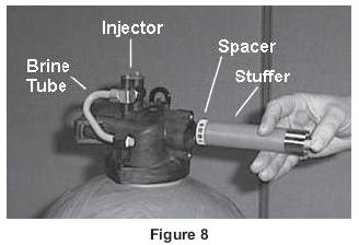
35 NOTE: Photos shown are for reference only for replacing the seal and spacer. Actual valve may be different. 1. Turn off water supply to valve. Next, cycle valve to backwash position, then to service. Now remove electrical plug from outlet, and cover from the control box. 2. Disconnect brine line from injector housing to brine valve (if unit has timed brine tank fill). 3. Remove the two capscrews that hold the back plate to the valve. 4. Grasp the back plate on both sides and slowly pull end plug and piston assembly out of the valve body (see Figure 5) and lay aside. 5. Remove the seal first using the wire hook with the finger loop (see Figure 6). 6. The spacer tool (use only for removing the spacers) has three retractable pins, retained by a rubber ring, at one end. They are retracted or pushed out by pulling or pushing the center button the opposite end. 7. Insert the pin end of the spacer tool into the valve body with the pins retracted (button pulled back). Push the tool tight against the spacer and push the button in, (seefigure 7). When the button is pushed in, the pins are pushed out to engage the 1/4 dia. holes in the spacer. Remove the tool from the valve body. The spacer will be on the end. Pull the center button back, the pins will be retracted and the spacer can be removed from the spacer tool. 8. Alternately remove remaining seals and spacers in accordance with steps 5 and The last or end spacer does not have any holes for the pins of the spacer tool to engage, therefore if the end spacer does not come out on the first try, try again using the wire hook with the finger loop. 10. To replace seals, spacers and end ring, use special tool with the brass sleeve on one end. This is a double-purpose tool (seefigure 8). The male end acts as a pilot to hold the spacers as they are pushed into the valve body and the brass female end is used to insert the seals into the valve body. 11. To restuff a valve body, first take the end ring (the plastic or brass ring without holes), then with your thumb press the button on the brass sleeve end. The large dia. inner portion is now exposed (see Figure 8). Place the end ring on this pilot with the lip on the end ring facing the tool. Push the tool into the valve body bore until it bottoms. While the tool is in the valve body, take a seal and press it into the inside diameter of the exposed brass female end. 12. Remove the tool, turn it end for end and insert it into the valve body bore. While holding the large dia. of the tool, slide it all the way into the valve body bore until it bottoms. Then push the center button to push the seal of the tool and leave it in place in the valve body. 13. Remove tool from valve body and push center on brass female end to expose the pilot on opposite end. Place a spacer on this end and insert the spacer and tool into the valve. 33
36 10.8 Pre-Treatment Lockout 34
37 11.0 Programming Tables For Industrial Fleck 2850SXT Table Water Softener Fleck 2850 SXT Industrial Model Number Tank Size (Dia x Height) 16 x x x x x 72 Cubic Feet Resin Injector Size #4 #4 #4 #4 #4 Refill Flow Control Backwash Flow Control Programming Step Description DISPLAY FORMAT DF US/Metric GAL GAL GAL GAL GAL VT VALVE TYPE STANDARD DOWNFLOW DOUBLE BACKWASH df2b df2b df2b df2b df2b CONTROL TYPE CT Day of Week day day day day day REGENERATION TIME RT Set Desired Time : : : : : Regeneration Cycles B1 1 st Backwash 10MIN 10MIN 10MIN 10MIN 10MIN BD Brine Draw 60MIN 60MIN 60MIN 60MIN 60MIN B2 2 nd Backwash 5MIN 5MIN 5MIN 5MIN 5MIN RR Rapid Rinse 10MIN 10MIN 10MIN 10MIN 10MIN BF Brine Refill 11MIN 14MIN 19MIN 26MIN 37MIN Regeneration Days of the Week Set Desired Days to Regenerate SET EACH DAY ON or OFF D1 = Sun, D2 = Mon, D3 = Tue, D4 = Wed, D5 = Thurs, D6 = Fri, D7 = Sat CD Current Day of Week SET SET SET SET SET * 15 Lbs. per Cubic Foot. 35
38 Table Carbon Filter Fleck 2850 SXT Industrial Model Number Tank Size (Dia x Height) 18 x x x 72 Cubic Feet Carbon Backwash Flow Control Programming Step Description DISPLAY FORMAT DF US/Metric GAL GAL GAL VT VALVE TYPE STANDARD DOWNFLOW SINGLE Fltr Fltr Fltr CT RT BACKWASH CONTROL TYPE Time Clock day day day REGENERATION TIME Set Desired Time : : : BW 1 Backwash 10MIN 10MIN 10MIN RR 2 Rinse 10MIN 10MIN 10MIN Regeneration Days of the Week Set Desired Days to Regenerate SET EACH DAY ON or OFF D1 = Sun, D2 = Mon, D3 = Tue, D4 = Wed, D5 = Thurs, D6 = Fri, D7 = Sat CD Current Day of Week SET SET SET Table Multi-Media Filter Fleck 2850 SXT Industrial Model Number Tank Size (Dia x Height) 16 x x x 62 Cubic Feet Media Backwash Flow Control Programming Step Description DISPLAY FORMAT DF US/Metric GAL GAL GAL VT VALVE TYPE STANDARD DOWNFLOW SINGLE Fltr Fltr Fltr CT RT BACKWASH CONTROL TYPE Time Clock day day day REGENERATION TIME Set Desired Time : : : BW 1 Backwash 10MIN 10MIN 10MIN RR 2 Rinse 10MIN 10MIN 10MIN Regeneration Days of the Week Set Desired Days to Regenerate SET EACH DAY ON or OFF D1 = Sun, D2 = Mon, D3 = Tue, D4 = Wed, D5 = Thurs, D6 = Fri, D7 = Sat CD Current Day of Week SET SET SET 36
Softeners Clack Model V125DTH Medical / Industrial Series Operation and Service Manual
 Softeners Clack Model V125DTH Medical / Industrial Series Operation and Service Manual www.ameriwater.com 800-535-5585 AmeriWater LLC 3345 Stop 8 Rd. Dayton, OH 45414 Clack Softener Manual, 98-0180 Rev.
Installation and Instructions 2. Product Features 3-6. Key Pad Functions 7. Distributor Information Programming Guide 8. Master Programming Guide 9-14
 Installation and Instructions 2 Product Features 3-6 Key Pad Functions 7 Distributor Information Programming Guide 8 Master Programming Guide 9-14 Dimensional Drawing 15 D-STC & D-SMM Valve Assembly 16-17
Operation Manual. Carbon Filtration Industrial Drive, Orlinda, TN fax
 Operation Manual Carbon Filtration 615-654-4441 sales@specialtyh2o.com 615-654-4449 fax TABLE OF CONTENTS Section 1 GENERAL 1.1 Warnings and Cautions... 1 1.2 Theory of Operation... 2 1.3 System Illustration...
DRS4-RM Manual. Set Up Instructions for DRS4 Series Single Tank
 Set Up Instructions for DRS4 Series Single Tank Inspect the packaging of the equipment to confirm that nothing was damaged during shipping. (Figure 1) Remove the resin tank(s) and valve(s) from the packaging.
Easy Nest Kits. Installation Suggestions
 Easy Nest Kits Installation Suggestions 2 General Recommendations Hydraulics Vacuum breakers should be installed to prevent siphoning. Flexible connectors should follow FRP tank manufacturers recommendations.
NORMAL OPERATING DISPLAYS GENERAL OPERATION
 SunTapWat e rsys t e ms WS1Cl ac kwat e rsof t ne r Owne r smanual MAIN COMPONENTS Your water treatment system is a point of entry (POE) system composed of three components: A. The control valve and computer
US Water Systems Synergy Model 9000/9100/9500 Service Manual
 US Water Systems Synergy Model 9000/9100/9500 Service Manual IMPORTANT: Fill in Pertinent Information on Page 3 for Future Reference IMPORTANT PLEASE READ: The information, specifications and illustrations
AQUAMATIC EASY NEST KITS INSTALLATION SUGGESTIONS
 AQUAMATIC EASY NEST KITS INSTALLATION SUGGESTIONS TABLE OF CONTENTS TABLE OF CONTENTS...2 GENERAL RECOMMENDATIONS...2 TROUBLESHOOTING GUIDE...3 EXISTING EASY NEST SYSTEM TROUBLESHOOTING GUIDE...4 COMPONENT
INSTALLATION & START-UP INSTRUCTIONS FLECK 9100SXT METER TWIN ALTERNATING WATER SOFTENER SYSTEMS
 INSTALLATION & START-UP INSTRUCTIONS FLECK 9100SXT METER TWIN ALTERNATING WATER SOFTENER SYSTEMS 1999-2007 QualityWaterForLess.com - 1 - info@qualitywaterforless.com Preface: Thank you for your purchase
SpectraPure PUMPED RO SYSTEMS (PSP) User s Manual for PSP-1500 Systems
 User s Manual for PSP-1500 Systems") SpectraPure PUMPED RO SYSTEMS (PSP) User s Manual for PSP-1500 Systems 2 3 PSP-1500 SYSTEM DESCRIPTION Reverse Osmosis RO Reverse Osmosis utilizes the unique properties of a semi-permeable membrane to
SpectraPure PUMPED RO SYSTEMS (PSP) User s Manual for PSP-1500 Systems 2 3 PSP-1500 SYSTEM DESCRIPTION Reverse Osmosis RO Reverse Osmosis utilizes the unique properties of a semi-permeable membrane to
CART FOR CENTURION 1500+
 CART FOR CENTURION 1500+ Operation & Maintenance Manual www.ameriwater.com 800-535-5585 AmeriWater 3345 Stop 8 Rd. Dayton, OH 45414 98-0161 Rev A Contents 1. GENERAL INFORMATION... 1 1.1. Features...
265 Series Valve Operation Manual
 265 Series Valve Operation Manual Note: 1. Read all instructions carefully before operation. 2. Avoid pinched o-rings during installation by applying (provided with install kit) NSF certified lubricant
The ultimate in water softening
 Calming troubled waters Metered Water Softener Specification MODEL: CALSOFT M The ultimate in water softening Due to Calmag s commitment to new product development the photographs contained within these
1020 Industrial Drive, Orlinda, TN fax
 Operation Manual Ultrafiltration for High Purity Distribution K-A-HPTUF Series 615-654-4441 sales@specialtyh2o.com 615-654-4449 fax TABLE OF CONTENTS Section 1 GENERAL 1.1 Warnings and Cautions... 1 1.2
Pure Water Power Purification System 4-Stage RODI Operations Manual
 Pure Water Power Purification System 4-Stage RODI Operations Manual Flush Valve Lever Quick Disconnect for RO Water Testing Water Supply In Drain Hose Pure Water Out to Waterfed Pole New Machine Setup
INSTALLATION & START-UP INSTRUCTIONS. Clack WS1 & WS1.25 METER WATER SOFTENER SYSTEMS
 INSTALLATION & START-UP INSTRUCTIONS Clack WS1 & WS1.25 METER WATER SOFTENER SYSTEMS 1999-2009 QualityWaterForLess.com - 1 - info@qualitywaterforless.com Preface: Thank you for your purchase of a new Water
Owners Manual Models: 075-AQF-CX. Aquatrol Backwashing Catalytic Carbon Filter. Visit us online at.
 Visit us online at www.uswatersystems.com Aquatrol Backwashing Catalytic Carbon Filter Owners Manual Models: 075-AQF-CX REVISION # 1.0 REVISION DATE October 11, 2017 US Water Systems, Inc. 1209 Country
Performa Cv Twin Alternating and High Flow Systems. Manual Supplement
 Performa Cv Twin Alternating and High Flow Systems Manual Supplement Table of Contents 1.0 Installation and Start-Up.............. 3 Water Line Connection Brine Tank Turbine Connection Connecting Manifold
Autotrol Performa ProSoft
 Autotrol Performa ProSoft With 960 Series Control 5-Cycle Conditioner 5-Cycle FA Filter Water Conditioning Control System Installation, Operation and Maintenance Manual Table of Contents Installation.....................................
Duplex Commercial Softeners
 Duplex Commercial Softeners Installation, Operation & Maintenance Guide Manual 003.1 Contents Page 1. Unpacking Instructions 3 2. Installation 4 Pre-installation checks Fitting the bottom distribution
Commercial Softeners. Installation, Operation & Maintenance Guide. Manual 002.1
 Commercial Softeners Installation, Operation & Maintenance Guide Manual 002.1 Contents Page 1. Unpacking Instructions 3 2. Installation 3 Pre-installation checks Fitting the bottom distribution system
PROPORTIONING VALVE. Model 150 INSTRUCTION MANUAL. March 2017 IMS Company Stafford Road
 PROPORTIONING VALVE Model 150 INSTRUCTION MANUAL March 2017 IMS Company 10373 Stafford Road Telephone: (440) 543-1615 Fax: (440) 543-1069 Email: sales@imscompany.com 1 Introduction IMS Company reserves
O&M Receiving and Inspection. Storage of Water Treatment Media
 O&M 105.1 Receiving and Inspection 1. Equipment should be checked against the Bill of Lading to verify that the number of pieces received matches those shipped. 2. Equipment should be carefully inspected
Pressure Dump Valve Service Kit for Series 2300 Units
 Instruction Sheet Pressure Dump Valve Service Kit for Series 00 Units. Overview The Nordson pressure dump valve is used to relieve hydraulic pressure instantly in Series 00 applicator tanks when the unit
SOFTENER D-DF & D-UF Series
 Water conditioning System. SOFTENER D-DF & D-UF Series INSTRUCTION MANUAL, OPERATION & MAINTENANCE 1. - PRESENTATION. In this manual, what is described are the required actions for the instalment, start
Pressure Dump Valve Service Kit for Series 3000 Units
 Instruction Sheet Pressure Dump Valve Service Kit for Series 000 Units. Overview The Nordson pressure dump valve is used to relieve hydraulic pressure instantly in Series 00, 400, 500, and 700 applicator
Chloramines Removal Filter CLF20 and CLF35 Models
 Chloramines Removal Filter CLF20 and CLF35 Models Operating and Maintenance Manual #51793 Rev. 6/09 Performance and Specifications Recommended Mineral Installation Shipping Item Model Media Flow Rate Tank
Tech Manual Powerline Softener (PS) Series
 Series") Tech Manual Powerline Softener (PS) Series Models: PS 2161 PS 2465 PS 2472 PS 3072 PS 3657 PS 3672 PS 4272 PS 4872 Page - 1 TABLE OF CONTENTS General Information About this Manual...3 The Powerline Product
Tech Manual Powerline Softener (PS) Series Models: PS 2161 PS 2465 PS 2472 PS 3072 PS 3657 PS 3672 PS 4272 PS 4872 Page - 1 TABLE OF CONTENTS General Information About this Manual...3 The Powerline Product
MUELLER. Mega-Lite Drilling Machine. Reliable Connections. table of contents PAGE. Equipment 2. Operating Instructions 3-4. Parts Information 5
 operating Instructions manual MUELLER Mega-Lite Drilling Machine table of contents PAGE Equipment 2 Operating Instructions 3-4 Parts Information 5 Travel Charts 6-11! WARNING: 1. Read and follow instructions
Autotrol Performa Filter Valve Series
 TM Autotrol Performa Filter Valve Series 440i Control 940F Control 960F Control Water Conditioning Control System Installation, Operation and Maintenance Manual Table of Contents Installation............................
Light Commercial Reverse Osmosis System. EE-1000 Manual
 Light Commercial Reverse Osmosis System EE-1000 Manual Nimbus Water Systems 41840 McAlby Court, Suite A Murrieta, CA 92562 800-451-9343 Fax 951-894-2801 www.nimbuswater.com Nimbus Water Systems 1 EE-1000
E L E C T R O N I C S X T
 1 - VAV OPRATO Regeneration button. ervice indicator: - Valve in service: lighted icon - ight regeneration: flashing icon nformation indicator, viewed in Diagnostic & rror modes ndicator in programmation
Misaligned Folds Paper Feed Problems Double Feeds Won t Feed FLYER Won t Run iii
 Operator s Manual Table of Contents Operator Safety... 1 Introduction... 2 Unpacking and Setup... 3 Unpacking... 3 Setup... 4 FLYER Overview... 5 FLYER Diagram... 5 Capabilities... 5 Control Panel... 6
TECHNICAL DATA MAINTENANCE AIR COMPRESSOR MODEL G-1
 Dry 131h 1. DESCRIPTION The Viking Model G-1 Maintenance Air Compressor is an electric motor-driven, aircooled, single-stage, oil-less compressor. The unit is equipped with a check valve and provides a
Installation of Your SprayMaster System
 Installation of Your SprayMaster System 1. At the installation site, remove all equipment from the corrugated box and the polyethylene drum and replace the drum lid. Check the picture to identify each
Geotech 1.66 Auto-Reclaimer Installation and Operation
 Geotech 1.66 Auto-Reclaimer Installation and Operation Rev 10/19/12 Part # 16600165 TABLE OF CONTENTS CHAPTER 1: SYSTEM DESCRIPTION... 3 FUNCTION AND THEORY... 3 SYSTEM COMPONENTS... 4 CHAPTER 2: SYSTEM
Hydraulic Punch Drivers
 SERVICE MANUAL 7804SB / 7806SB Quick Draw 7704SB / 7706SB Quick Draw Flex Quick Draw Hydraulic Punch Drivers Serial Codes AHJ and YZ Read and understand all of the instructions and safety information in
Geotech 1.66 Auto-Reclaimer
 Geotech 1.66 Auto-Reclaimer Installation and Operation Rev 9 8/31/06 Part # 16600165 TABLE OF CONTENTS CHAPTER 1: SYSTEM DESCRIPTION... 3 FUNCTION AND THEORY... 3 SYSTEM COMPONENTS... 4 CHAPTER 2: SYSTEM
FOR INSTALLING CO 2 BLENDER KIT (P/N IN BEER SYSTEM
 IMI CORNELIUS INC One Cornelius Place Anoka, MN 55303-623 Telephone (800) 238-3600 Facsimile (612) 22-326 INSTALLATION INSTRUCTIONS FOR INSTALLING CO 2 BLENDER KIT (P/N 111612000 IN BEER SYSTEM SECONDARY
BS Series Basket Strainer
 BS Series Basket Strainer Operating, Installation, & Maintenance Manual Corrosion Resistant Fluid and Air Handling Systems. Dated 04-26-12 PRESSURE DROP SIMTECH strainers are engineered to offer the lowest
CS150 CAP STAPLER OWNER S MANUAL
 Operation Revised 6/2013 www.stingerworld.com CS150 CAP STAPLER OWNER S MANUAL! Maintenance Safety Warranty PLEASE READ! This manual contains important information about product safety. WELCOME TO STINGER
TECHNICAL DATA CAUTION
 Page 1 of 6 1. DESCRIPTION The Viking Model D-2 Accelerator is a quick-opening device, with an integral anti-flood assembly, used to increase the operating speed of a differential type dry pipe valve.
Booster Pump PB4-60 Replacement Kits
 Booster Pump PB4-60 Replacement Kits FOR YOUR SAFETY - This product must be installed and serviced by a contractor who is licensed and qualified in pool equipment by the jurisdiction in which the product
accidents which arise due to non-observance of these instructions and the safety information herein. SPECIFICATIONS
 18 GAUGE 1-1/4 INCH BRAD NAILER Model: 7611 CALIFORNIA PROPOSITION 65 WARNING: You can create dust when you cut, sand, drill or grind materials such as wood, paint, metal, concrete, cement, or other masonry.
REVERSE OSMOSIS WATER FILTRATION SYSTEM MODEL EWR 4075 INSTRUCTION MANUAL
 REVERSE OSMOSIS WATER FILTRATION SYSTEM MODEL EWR 4075 INSTRUCTION MANUAL Excalibur Water Systems 142 Commerce Park Drive, Unit M & N Barrie, Ontario L4N 8W8 CANADA www.excaliburwater.com 2013.05.7446
Concentrate Distribution System (Stand Mounted) A-CDS-70-X & A-CDS-TANK-X-ST Industrial Drive, Orlinda, TN 37141
 A-CDS-70-X & A-CDS-TANK-X-ST Industrial Drive, Orlinda, TN 37141") 0 Operation Manual Concentrate Distribution System (Stand Mounted) A-CDS-70-X & A-CDS-TANK-X-ST 615-654-4441 sales@specialtyh2o.com 615-654-4449 fax TABLE OF CONTENTS Section 1 GENERAL 1.1 Warnings and
0 Operation Manual Concentrate Distribution System (Stand Mounted) A-CDS-70-X & A-CDS-TANK-X-ST 615-654-4441 sales@specialtyh2o.com 615-654-4449 fax TABLE OF CONTENTS Section 1 GENERAL 1.1 Warnings and
Halsey Taylor Owners Manual STOP!
 Halsey Taylor Owners Manual 4710 Freeze Resistant Floor Mounted Steel Fountain STOP! PLEASE READ THE FOLLOWING INFORMATION. ITALLATION ITRUCTIO FOR THE 4710FR FTN. WITH 97243C SINGLE VALVE CONTROL ASSEMBLY
Owner s Manual. R&M Water Group TM. Models: SA-TECH PLUS 40 DB SA-TECH PLUS 48 DB
 TM Owner s Manual Models: SA-TECH PLUS 40 DB SA-TECH PLUS 48 DB R&M Water Group TM Water Conditioning & Purification Systems A Division of Water Technologies, Inc. 28 South 1550 West, Lindon, Utah 84042
Installation and Use Manual
 Installation and Use Manual EMASMB & LMASMB Surface Mount Bottle Filling Stations Model EMASMB IMPORTANT THIS IS AN INDOOR APPLICATION ONLY! ALL SERVICE TO BE PERFORMED BY AN AUTHORIZED SERVICE PERSONNEL.
Sterisil Ac+ Installation & Operating Manual
 Sterisil Ac+ Installation & Operating Manual 719 622 7200 Sterisil.com Arbor Dental Associates 2 Table of Contents Introduction 4 Sterisil Ac + Features 5 Installation Instructions 6 Maintenance 10 Troubleshooting
Sand Dollar Filter Owner s Manual IMPORTANT SAFETY INSTRUCTIONS SAVE THESE INSTRUCTIONS READ AND FOLLOW ALL INSTRUCTIONS SAVE THESE INSTRUCTIONS
 SAVE THESE INSTRUCTIONS Pentair Pool Products P/N 99223000 12 Rev. E 2-22-02 Sand Dollar Filter Owner s Manual IMPORTANT SAFETY INSTRUCTIONS READ AND FOLLOW ALL INSTRUCTIONS SAVE THESE INSTRUCTIONS Table
RIX COMPRESSORS. MICROBOOST Owner s Manual CONFIGURATION A MB-115 MB-230. November 21, 2002 APPLICABILITY [ A]
![RIX COMPRESSORS. MICROBOOST Owner s Manual CONFIGURATION A MB-115 MB-230. November 21, 2002 APPLICABILITY [ A]](/thumbs/77/74792841.jpg "RIX COMPRESSORS. MICROBOOST Owner s Manual CONFIGURATION A MB-115 MB-230. November 21, 2002 APPLICABILITY [ A]") RIX COMPRESSORS MICROBOOST Owner s Manual CONFIGURATION A MB-115 MB-230 November 21, 2002 APPLICABILITY [ A] INTRODUCTION Safety This electromechanical equipment is designed to produce high pressure gas.
RIX COMPRESSORS MICROBOOST Owner s Manual CONFIGURATION A MB-115 MB-230 November 21, 2002 APPLICABILITY [ A] INTRODUCTION Safety This electromechanical equipment is designed to produce high pressure gas.
Halsey Taylor Owners Manual 4410 Freeze Resistant Tubular Fountain STOP!
 Halsey Taylor Owners Manual 4410 Freeze Resistant Tubular Fountain STOP! PLEASE READ THE FOLLOWING INFORMATION. ITALLATION ITRUCTIO FOR THE 4410FR FTN. WITH 97243C SINGLE VALVE CONTROL ASSEMBLY ARE LOCATED
Installation & Instruction Manual For Portable Series R.O. units:
 Installation & Instruction Manual For Portable Series R.O. units: Please read carefully before proceeding with installation *System components and appearance may vary from above image. REPLACEMENT AND
CS Controlled Dissolved Gas assembly with optional CS Air Aspirator assembly. Installation and Operation information
 CS-425-01 Controlled Dissolved Gas assembly with optional CS-603-01 Air Aspirator assembly Installation and Operation information Serial # CS-XXX Date of shipment:, 2005 Shipped to: Purchase order #: xxxxxxx
accidents which arise due to non-observance of these instructions and the safety information herein. SPECIFICATIONS
 18 GAUGE 2 INCH BRAD NAILER Model: 7555 CALIFORNIA PROPOSITION 65 WARNING: You can create dust when you cut, sand, drill or grind materials such as wood, paint, metal, concrete, cement, or other masonry.
INSTRUCTION MANUAL. Gas Salamander
 INSTRUCTION MANUAL Gas Salamander This manual contains important information regarding your unit. Please read this manual thoroughly prior to equipment set-up, operation and maintenance. Failure to comply
Instructions for SILEX 1C Mixed bed cartridge filter
 D01B-30A-UK1 January 2017 Instructions for SILEX 1C Mixed bed cartridge filter With conductivity sensor Gravity flow or pressure installation SILHORKO-EUROWATER A/S Phone +45 86 57 12 22 DK-8660 Skanderborg
Water Weir Flow Controller. Introduction. Safety Precautions. Mounting the Hardware
 57007-88 Introduction Safety Precautions This instruction sheet describes how to set up and use the Hach (Figure 1). A water weir is a device that raises or diverts water to regulate the flow. Hach s water
Technical Topics. Softener Elution Studies TT
 Technical Topics TT-035-1204 Water softeners are critical components in many commercial and industrial water-using systems. By removing calcium and magnesium ions (hardness) from a facility s or system
SPECIFICATIONS Type: Twin stack, single phase Tank: 4 gallon Air Output: PSI; PSI Max PSI: 125 PSI HP: 1.
 2 GALLON TWIN STACK AIR COMPRESSOR Model: 9526 DO NOT RETURN TO STORE. Please CALL 800-348-5004 for parts and service. CALIFORNIA PROPOSITION 65 WARNING: You can create dust when you cut, sand, drill or
ATD LB PRESSURE BLASTER INSTRUCTION MANUAL
 ATD-8402 90LB PRESSURE BLASTER INSTRUCTION MANUAL SAVE THESE INSTRUCTIONS SAFETY INSTRUCTIONS FOR SANDBLASTER 1. Before opening the tank release the air pressure on the sand tank. To do this, turn off
UltRo Dual Flow Reverse Osmosis Water System
 UltRo Dual Flow Reverse Osmosis Water System Congratulations on this great investment to your health. **IMPORTANT NOTE BEFORE YOU BEGIN** We recommend you call your local friendly plumber to ensure proper
Model VR6 System. Installation, Operation & Maintenance
 Model VR6 System Installation, Operation & Maintenance General: All Archer Instruments chlorination systems are carefully designed and tested for years of safe, accurate field service. All Archer Instruments
Assembly Drawing: W-311B-A01, or as applicable Parts List: W-311B-A01-1, or as applicable Special Tools: , , &
 REDQ Regulators Model 411B Barstock Design Powreactor Dome Regulator OPERATION AND MAINTENANCE Contents Scope..............................1 Installation..........................1 General Description....................1
AIR-OPERATED DOUBLE DIAPHRAGM PUMP USER S MANUAL
 00, 0, 000 00, 000, 00 A. TECHNICAL INFORMATION Model 00 Inlet/Outlet " Air Inlet /" 0 / 000 /" /" 00 /" /" 000 /" /" 00 /" /" Flow Rate GPM/ 0LPM GPM/ 0LPM GPM/ LPM GPM/ LPM GPM/ 0LPM GPM/ 0LPM Maximum
ACTIVATE YOUR WARRANTY BY REGISTERING YOUR PRODUCT AT
 OWNER'S MANUAL MAX Specialty Series with Triton Metered and Timered Electronic Control Valves ACTIVATE YOUR WARRANTY BY REGISTERING YOUR PRODUCT AT www.watertech.com or call 888-254-8412 Dealer Contact
Installation, Operation and Maintenance Manual for Back Pressure Regulator
 Installation, Operation and Maintenance Manual for Back Pressure Regulator Model 8860 2009 Groth Corporation IOM-8860 Rev. B 12541 Ref. ID: 95565 Page 2 of 13 Table of Contents I. INTRODUCTION 3 II. DESIGN
FlashGARD HP Reverse Osmosis Filtration System Model Number FSTMO75 Part Number
 3M Water Filtration Products FlashGARD HP Reverse Osmosis Filtration System Model Number FSTMO75 Part Number 56123-06 Installer: Please leave this manual with owner/operator. End User: Please retain for
KJ4000 Operating Instructions & Parts Manual NSN
 KJ4000 Operating Instructions & Parts Manual NSN 1025-01-473-7710 Mandus Group Ltd. KJ4000 Operators Manual Date: 3 Jan. 2002 TABLE OF CONTENTS General Safety Instructions...Page 1 Operator Instructions...Page
NXT 5 Pure Water System
 NXT 5 Pure Water System Effective February, 2019 Pure Water Window Cleaning System Operation and Maintenance Manual Overview Congratulations on your purchase. Thank you for purchasing the NXT 5 Pure Water
HPB25 Hydraulic Paving Breaker
 INSTRUCTION MANUAL HPB25 Hydraulic Paving Breaker Read and understand all of the instructions and safety information in this manual before operating or servicing this tool. Register this product at www.greenlee.com
4 IN. BALL LAUNCHER Engine Mounted / PTO Driven
 4 IN. BALL LAUNCHER Engine Mounted / PTO Driven OPERATOR S PARTS and MAINTENANCE MANUAL 2006 EDITION BL-MAN-4EN Creation Revision date: 10MAR06 date: by: Ivon LeBlanc by: Table of Contents Table of Contents...
Training. Testor Training Manual
 Training Testor Training Manual Index Section 1 Introduction and Safety Warnings Section 2 Test Procedures Section 3 Test Hoses Section 4 Fault Location 1:1 1.1 Introduction The Dräger Testor test equipment
DS06D,G Dial Set Pressure Regulating Valve
 DS06D,G Dial Set Pressure Regulating Valve PRODUCT DATA FEATURES APPLICATION Built-in, factory-calibrated outlet pressure adjustment dial. Noncorroding unitized cartridge contains all working parts and
INSTALLATION INSTRUCTIONS. CVS 67CFR Pressure Reducing Instrument Supply Regulator INTRODUCTION
 INSTALLATION INSTRUCTIONS CVS 67CFR Pressure Reducing Instrument Supply Regulator INTRODUCTION The CVS Controls 67CFR Filter regulator is a pressure reducing supply regulator typically used for pneumatic
Service and Repair Manual
 II stage R2 Ice/ Special, II stage R 1 Pro DOWNSTREAM 2 nd STAGE REGULATOR Service and Repair Manual Introduction Safety Precautions...4 General Procedures, Maintenance Schedules...5 Initial Inspection
INSTALLATION, CARE & USE MANUAL. EMASMB & LMASMB Surface Mount Bottle Filling Stations
 INSTALLATION, CARE & USE MANUAL EMASMB & LMASMB Surface Mount Bottle Filling Stations IMPORTANT THIS IS AN INDOOR APPLICATION ONLY! ALL SERVICE TO BE PERFORMED BY AN AUTHORIZED SERVICE PERSONNEL. TOOLS/ITEMS
Installation Troubleshooting Maintenance Instructions Installation / Start-up
 Model ZW207 Installation Troubleshooting Maintenance Instructions Installation / Start-up NOTE: Flushing of all pipe lines is to be performed to remove all debris prior to installing valve. 1. For making
SWIRLFLO Refrigerated fountains with FLEXI-GUARD
 TM INSTALLATION, CARE & USE MANUAL SWIRLFLO Refrigerated fountains with FLEXI-GUARD TM INSTALLER! CAUTION: Review these instructions before beginning installation. Be sure that installation conforms to
INDUSTRIAL VALVES MODELS: C62-A; C62-D. INSTRUCTION MANUAL Installation Operation Parts Service DIAPHRAGM BYPASS PRESSURE REGULATING VALVES
 INSTRUCTION MANUAL Installation Operation Parts Service IMPORTANT Record your Regulator model number and serial number here for easy reference: Model No. Serial No. Date of Purchase When ordering parts
Accu-Tab Systems 2000 P Series by Axiall Corporation
 Accu-Tab Systems 2000 P Series by Axiall Corporation Installation and Operating Instructions Models 2075 P 2150 P For NSF/ANSI-Standard 61 NSF STANDARD 61 applications use NSF/ANSI Standard 60 listed Axiall
Multi-Probe Sampling System User Guide & Manual
 Multi-Probe Sampling System User Guide & Manual Rev. 06/05/12 Part #22200012 Table of Contents CHAPTER 1: SYSTEM DESCRIPTION... 2 FUNCTION AND THEORY... 3 SYSTEM COMPONENTS... 4 CHAPTER 2: SYSTEM INSTALLATION...
CAN 565 Series. Softener Manual
 CAN 565 Series Softener Manual Note: 1. Read all instructions carefully before operation. 2. Avoid pinched o-rings during installation by applying (provided with install kit) NSF certified lubricant to
EASTERN ENERGY SERVICES PTE LTD. 60 Kaki Bukit Place #02-19 Eunos Tech Park Singapore, SG Singapore Telephone: Fax:
 2 Table Of Contents 1. Introduction 3 2. About this Manual 3 3. Contacting YZ Systems 3 4. Vessel Components 4 5. Specifications 5 6. Application 6 7. Theory of Operation 7 8. DuraSite Installation & Use
Installation, Operation, and Maintenance Manual. Welker Constant Pressure Cylinder With Solid Indicator (Non-mixer) Model CP-30SI
 Model CP-30SI") Installation, Operation, and Maintenance Manual Welker Constant Pressure Cylinder With Solid Indicator (Non-mixer) Model The information in this manual has been carefully checked for accuracy and is intended
Installation, Operation, and Maintenance Manual Welker Constant Pressure Cylinder With Solid Indicator (Non-mixer) Model The information in this manual has been carefully checked for accuracy and is intended
AIR COMPRESSOR. Failure to follow all instructions as listed below may result in electrical shock, fire, and/or serious personal injury.
 2 GALLON AIR COMPRESSOR Model: 7517 DO NOT RETURN TO STORE. Please CALL 800-348-5004 for parts and service. CALIFORNIA PROPOSITION 65 WARNING: You can create dust when you cut, sand, drill or grind materials
OWNER S MANUAL & INSTALLATION GUIDE
 OWNER S MANUAL & INSTALLATION GUIDE MicroTurb Premium Series Turbidity Filters w/ NextSand highly effective and economical sediment / turbidity / particulate reduction filters with higher flow rates, lower
IWT 565 Series HTO Series Operation Manual
 IWT 565 Series HTO Series Operation Manual Note: 1. Read all instructions carefully before operation. 2. Avoid pinched o-rings during installation by applying (provided with install kit) NSF certified
D05 Pressure Regulating Valves
 D05 Pressure Regulating Valves FEATURES PRODUCT DATA Noncorroding unitized cartridge contains all working parts and is easily replaceable. Includes built-in strainer and thermal bypass. Balanced seat construction
MUELLER. A Wall Type. Indicator Post. Reliable Connections. General Information 2. Technical Data/ Dimensions 3. Installation 4-5.
 Installation Instructions manual MUELLER table of contents PAGE A-20814 Wall Type General Information 2 Technical Data/ Dimensions Installation 4-5 Maintenance 6 Parts 7 Indicator Post! WARNING: 1. Read
IMPORTANT PLEASE READ BEFORE COMMENCING INSTALLATION
 IMPORTANT PLEASE READ BEFORE COMMENCING INSTALLATION This Fitting Guide is designed to assist in the Installation of your Reverse Osmosis System. Some of the parts that are supplied with each system may
Vessel Installation and Operating Manual
 For In-ground and Aboveground Pools Vessel Installation and Operating Manual Important Safety Information Please read this manual prior to installation. Nature 2 Express is designed to sanitize in-ground
Endo-Flush Order # ZUTR30004 OPERATION MANUAL. Zutron Medical, LLC W 98 th St #40-27 Lenexa, KS Phone Fax
 OPERATION MANUAL Zutron Medical, LLC 17501 W 98 th St #40-27 Lenexa, KS 66219 Phone 877-343-5873 Fax 913-967-5944 ZUT-Lab-004-30004 REV. 03312017 Table of Contents 2 Introduction 1. Intended Use 2. Labels,
ULTRA PURE SYSTEMS 625 GPD RODI INSTALLATION AND OPERATION MANUAL
 ULTRA PURE SYSTEMS 625 GPD RODI INSTALLATION AND OPERATION MANUAL Thank you for choosing UPS (Ultra-Pure Systems) for your RO/DI solution. We are confident you have made the right decision. This system
AIR COMPRESSOR OPERATING INSTRUCTION AND PARTS LIST
 AIR COMPRESSOR OPERATING INSTRUCTION AND PARTS LIST OIL-LESS TYPE IMPORTANT: PLEASE READ CAREFULLY BEFORE STARTING OPERATIONS. THE CONTENTS ARE FOR GENERAL INFORMATION OF ALL THE SIMILAR MODELS. Record
INSTALLATION INSTRUCTIONS FOR GRT75-PF-RFS PET FOUNTAIN
 INSTALLATION INSTRUCTIONS FOR GRT75-PF-RFS PET FOUNTAIN Important: Read all instructions and refer to local codes prior to installation. l Local soil conditions may require more gravel for drainage. l
1020 Industrial Drive, Orlinda, TN fax
 Operation Manual Tank Distribution System A-UPT Series 615-654-4441 sales@specialtyh2o.com 615-654-4449 fax TABLE OF CONTENTS Section 1 GENERAL 1.2 Warnings and Cautions... 1 1.2 Theory of Operation...
Operation and Maintenance Manual for
 Operation and Maintenance Manual for KFZST KF Series Twin Softener Systems Catalog # Serial # USFilter 10 Technology Drive Lowell, Massachusetts 01851 Tel: (800) 875-7873 Fax: (978) 441-6025 Email: Lowell_TechSupport@USFilter.com
OPERATION MANUAL NTF-60 Plus
 OPERATION MANUAL NTF-60 Plus Nitrogen Tire Filling Valve Stem Caps (Qty=200) Order P/N 436075 RTI Technologies, Inc 10 Innovation Drive York, PA 17402 800-468-2321 www.rtitech.com 035-81264-00 (Rev A)