Pressure Relief Valve DHV 718
|
|
|
- Judith Sherman
- 5 years ago
- Views:
Transcription


1 Advantages frictionless components low maintenance low pressure increase up to fully opened valve constant low vibration controlling hermetically sealed by diaphragm for oscillating pumps for viscous media even slightly polluted Application chemical plants water treatment galvanotechnics Utilisation as pressure relief valve; constant working or primary pressure as overflow valve; opens in case of exceeding the set opening pressure Type of fluids Neutral and aggressive fluids even with few solid particles provided that the components getting in contact with the medium are resistant at operating temperature according to the ASV resistance guide. Examinations Requirements and examinations acc. to DIN 3441, 3442, 8063, 16962/3. Nominal pressure (H2O, 20 C) PN 10 Media temperature see pressure/temperature diagram Operating pressure see pressure/temperature diagram Set range 0,5-10 bar Opening pressure DN 8 0,5 bar DN ,3 bar optimized design, safe in function Hysteresis 0,5 bar Size DN 8 - DN 50 Housing DN 8 PVC-U, PP or PVDF DN PVC-U, PP or SS Bonnet (spring housing) PP, glass fibre reinforced Diaphragm EPDM, fabric reinforced and PTFE-coated on fluid side Adjustment and connecting screws SS Connection DN 8 DN DN union DIN 8063 with socket ends for solvent or fusion welding acc. to DIN/ISO spigot ends for solvent or fusion welding acc. to DIN/ISO socket end with pipe thread or NPT thread Mounting variable, bonnet preferably in upright position Flow direction direction of flow always in direction of arrow Fastening thread inserts for easiest mounting Colour housing PVC-U: grey, RAL 7011 PP: grey, RAL 7032 PVDF: opaque, yellowish-white bonnet orange, RAL


2 Sectional drawing DHV 718, DN 8 Sectional drawing DHV 718, DN 10 - DN 50 Function and design Normally the valve is closed and the diaphragm is only loaded by the low secondary pressure at the valve seat. Any rise of working or primary pressure lifts the diaphragm against the spring force. The valve opens and the pressure decreases. The flat diaphragm, constructed for full opening of the valve (D/4), safely separates the fluid from the spring housing. The only components getting in contact with the medium are the PTFE-coated diaphragm and the valve housing. In normal position the diaphragm seats on the well dimensioned valve seat. An inadmissible compression set at max. spring force is impossible. The valve housing is provided with a cavity. The diaphragm has the appropriate design and is inserted into the cavity. At compression due to the screw tightening torques there is no leakage, even at higher temperatures. Note In normal position the counter pressure (secondary pressure) may be approximately 4 times higher than the set pressure p E, the valve rests closed. Valve setting For reading the set pressure we recommend the installation of a diaphragm pressure gauge guard with pressure gauge in the primary line. 1. Pull off protection cap (DN 10 - DN 50). 2. Loosen counter nut at adjustment screw. 3. Turn adjustment screw clockwise (pressure increase) until the required set pressure or opening pressure is reached. 2
 the material of the valve is resistant against. For other media see the ASV resistance guide.")
 pressure loss Δp (bar) flow Q (l/h) Pressure loss and kv-value The diagram shows the pressure loss Δp over the flow Q.")
3 Pressure/temperature diagram pressure (bar) temperature ( C) The pressure/temperature limits are applicable for a computed operating life factor of 25 years at PN 10. The values are a guide for harmless fluids (DIN 2403) the material of the valve is resistant against. For other media see the ASV resistance guide. Durability of wear and tear parts is depending on the operating conditions of the application. Values below 0 C (PP < +10 C) on request with exact data of operation. Pressure loss curve (standard values for H2O, 20 C) pressure loss Δp (bar) flow Q (l/h) Pressure loss and kv-value The diagram shows the pressure loss Δp over the flow Q. For calculation: c v = k v 0,07 f v = k v 0,0585 Values: k v [l/min] c v [gal/min] US f v [gal/min] GB Operating instructions Attention Safe operation of the valve can only be ensured if it is properly installed, operated, serviced or repaired by qualified personnel according to its intended use while observing the accident prevention regulations, safety regulations, relevant standards and technical regulations or data sheets like DIN, DIN EN, DIN ISO and DVS* for example. The intended use includes adhering to the specified limit values for pressure and temperature as well as the check of the chemical resistance. For this purpose, ensure that all components getting in contact with the media are "resistant" in accordance with the ASV resistance guide. The owner/user must inform the authorized qualified personnel instructed to perform the assembly, inspection and/or maintenance work of any potential danger emanating from the machine line/medium, and ensure that suitable safety measures are observed. This includes also the consideration of local regulations and laws of the territories of use. If the authorized qualified personnel does not have any operating and maintenance instruction this is to be requested prior installation, maintenance or repair. Non-observance of the specified information and safety instructions may lead to injuries and/or property damages. Note At certain intervals the tightening torques at the housing screws should be checked. Admissible tightening torques for lubricated housing screws: size tightening torque (Nm) DN 8 2 DN 10 6 DN 15 6 DN 20 9 DN 25 9 DN DN DN
 - 3/8 1/2 3/4 1 1 1/4 1 1/2 2 PVDF/PVC-U/PP D 50,0 81,0 81,0 107,0 107,0 147,0 147,0 147,0 H 120,0 177,0 177,0 207,0 207,0 277,0 277,0 277,0 PVDF/PVC-U/PP h 20,0 25,0 25,0 37,0 37,0 57,0")
4 Housing: PVC-U, PP, PVDF Dimension d (mm) DN (mm) DN (Zoll) 1/4 3/8 1/2 3/ /4 1 1/2 2 pipe thread G (inch) - 3/8 1/2 3/ /4 1 1/2 2 thread NPT (inch) - 3/8 1/2 3/ /4 1 1/2 2 PVDF/PVC-U/PP D 50,0 81,0 81,0 107,0 107,0 147,0 147,0 147,0 H 120,0 177,0 177,0 207,0 207,0 277,0 277,0 277,0 PVDF/PVC-U/PP h 20,0 25,0 25,0 37,0 37,0 57,0 57,0 57,0 PVC-U L1 119,0 144±1,0 144±1,0 174±1,0 174±1,0 224±1,1 224±1,1 244±1,2 PP L1 119,0 144±2,1 144±2,1 174±2,6 174±2,6 224±3,3 224±3,3 244±3,6 PVDF L1 119,0 PVC-U/PP/PVDF L2 85, PVC-U/PP/PVDF L3 91, PVC-U/PP L4-94±1,0 94±1,0 130±1,0 130±1,0 162±1,0 176±1,0 188±1,0 PVC-U/PP l - 14,0 16,0 19,0 22,0 26,0 31,0 38,0 PVC-U/PP l1-16,0 18,0 20,0 22,0 24,0 26,0 30,0 M M 5 M 6 M 6 M 6 M 6 M 8 M 8 M 8 v 32,0 40,0 40,0 46,0 46,0 65,0 65,0 65,0 Weight (kg) View A View A View A d (mm) PVC-U socket/spigot 0,3 0,6 0,6 1,3 1,3 3,4 3,4 3,4 PP socket/spigot 0,2 0,5 0,5 1,1 1,1 2,9 2,9 2,9 PVDF socket 0, PVC-U threaded socket - 0,6 0,6 1,3 1,3 3,3 3,3 3,3 PP threaded socket - 0,5 0,5 1,1 1,1 2,9 2,9 2,9 4
 - 16 20 25 32 40 50 63 DN (mm) - 10 15 20 25 32 40 50 DN (inch) - 3/8 1/2 3/4 1 1 1/4 1 1/2 2 pipe thread G (inch) - 3/8 1/2 3/4 1 1 1/4 1 1/2 2 thread NPT (inch) - 3/8 1/2 3/4")
5 Housing: SS Dimension d (mm) DN (mm) DN (inch) - 3/8 1/2 3/ /4 1 1/2 2 pipe thread G (inch) - 3/8 1/2 3/ /4 1 1/2 2 thread NPT (inch) - 3/8 1/2 3/ /4 1 1/2 2 threaded socket D - 81,5 81,5 108,0 108,0 148,0 148,0 148,0 threaded socket H - 152,0 152,0 175,0 175,0 217,0 219,5 227,5 h - 16,0 16,0 24,0 24,0 27,5 30,0 35,0 L4-79,0 79,0 103,0 103,0 142,0 140,0 136,0 NPT-thread l2-11,0 15,0 16,0 18,0 20,0 22,0 25,0 pipe thread G l2-16,0 18,0 20,0 22,0 25,0 25,0 25,0 M - M 6 M 6 M 6 M 6 M 8 M 8 M 8 v Weight (kg) View A d (mm) Inox female thread - 1,7 1,7 4,4 4,4 9,4 9,9 11,1 5
 in relation to")


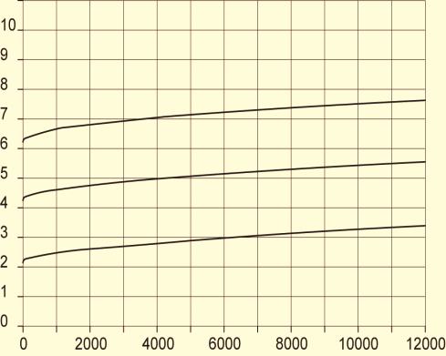
6 Characteristic curves DHV 718 for H2O, 20 C The valve curves show the working or primary pressure p A (bar) in relation to flow Q (l/h). The parameter is the set pressure p E, the valve is closed (Q = 0 l/h). The curve shows the progression of the opening pressure. Example: Size DN 10 The valve is set tight at 5 bar. At a pressure increase of 1 bar a flow of appr. 940 l/h is reached. According to the curve following values arise: Set pressure p E appr. 5,0 bar Working pressure p A appr. 6,0 bar Opening pressure p Ö appr. 5,4 bar Closing pressure p S appr. 4,5 bar Hysteresis (p Ö -p S ) appr. 1,0 bar DN 8 DN 10 DN 15 DN 20 DN 25 6


7 DN 32 DN 40 DN 50 7


8 Exploded view Pos. Piece Description 1 1 valve housing 2 1 bonnet pressure plate 5 1 spring plate spring spring 7 1 steel ball flat diaphragm* 10 4 socket head cap screw hexagonal nut 13 4 hexagonal nut 14 4 U-washer hexagonal srew O-ring 19 2 union nut insert 20 2 union nut * spare part Pos. Piece Description 1 1 valve housing 2 1 bonnet 3 1 diaphragm plate 4 1 pressure plate 5 1 spring plate 6 1 spring 7 1 steel ball 8 1 steel ball 9 1 flat diaphragm* 10 2 hexagonal screw 11 4 hexagonal screw 12 1 hexagonal nut 13 6 hexagonal nut 14 6 U-washer 15 6 U-washer 16 1 hexagonal screw 17 1 protection cap * spare part 8
9 < < < Applications of pressure relief valves 1. Constant system pressure 2. Consumer 1 and/or 2 opens, pressure relief valve closes p A p A p A p A p p Ö valve opens P p Ö p 1 p Ö valve closed 1 2 P p Ö p Ö 3. Pressure relief valve as overflow valve Pressure of container or plant system may not exceed the max. pressure value. 1 p A p Ö p Ö p A p Ö valve opens p Ö valve closed Failures, possible causes and repair p A = working pressure = pump pressure p Ö = opening pressure Failure Cause Repair Valve leaking at diaphragm. Diaphragm clamping pressure Fasten housing screws. too low. p Ö valve opens valve closed Pressure drops below set pressure. Diaphragm in the range of Replace diaphragm, if necessary, rectify seal seal seat defective. seat. High degree of pollution. Clean valve body. Pressure rises above set value. Secondary area is blocked. Clean valve. Valve is leaking at adjustment Diaphragm defective. Replace diaphragm. screw. 9
10 Housing: PVC-U connection spigot socket socket G thread NPT thread sealing - EPDM FPM - - d DN DN Id.-No. Id.-No. Id.-No. Id.-No. Id.-No. (mm) (mm) (inch) / / / / / / Housing: PP Housung: PVDF connection socket socket sealing EPDM FPM d DN DN Id.-No. Id.-No. (mm) (mm) (inch) / Housing: Inox connection G thread NPT thread sealing - - d DN DN Id.-No. Id.-No. (mm) (mm) (inch) / / / / / Diaphragm: EPDM/PTFE Diaphragm: EPDM/PTFE connection spigot socket socket G thread NPT thread sealing - EPDM FPM - - d DN DN Id.-No. Id.-No. Id.-No. Id.-No. Id.-No. (mm) (mm) (inch) / / / / / / Diaphragm: EPDM/PTFE Diaphragm: EPDM/PTFE /10/25 Technical alterations expected 10
11 11

12 12
Pressure relief valve DHV 716 set range: 0,5-10,0 bar
 Pressure relief valve DHV 7 set range: 0,5-0,0 bar Advantage pressure setting possible at any time, also during operation optimum monitoring valves high reproducibility of the set pressure high level of
Pressure relief valve DHV 712 DN 65-80: 0,5-10 bar, DN : 0,3-4 bar, DN 100: 0,5-6 bar
 Pressure relief valve DHV 7 DN 5-80: 0,5-0 bar, DN 5-00: 0, - bar, DN 00: 0,5 - bar Advantage for high pressure stability reliable reduction of pressure peaks and pulsations pressure setting possible at
Pressure relief valve DHV 725 set range: 0,2-10,0 bar
 Pressure relief valve DHV 75 set range: 0, - 0,0 bar Advantage pressure setting possible at any time, also during operation optimum monitoring valves high reproducibility of the set pressure high level
Pressure Reducing Valve DMV 755 set range: 1,0-9,0 bar
 Pressure Reducing Valve DMV 755 set range:,0-9,0 bar Advantage pressure setting possible at any time, also during operation high reproducibility of the set pressure high level of operating safety and long
Pressure Reducing Valve DMV 750 set range: bar
 Pressure Reducing Valve DMV 750 set range:.0-6.0 bar Advantage pressure setting possible at any time, also during operation hermetically sealed by valve diaphragm high level of operating safety and long
Pressure Reducing Valve DMV 750
 ASV Stübbe GmbH & Co. KG Hollwieser Straße 5 D-32602 Vlotho Fon +49 (0) 57 33-7 99-0 Fax +49 (0) 57 33-7 99-2 00 www.asv-stuebbe.de contact@asv-stuebbe.de Pressure Reducing Valve DMV 750 Advantages reduction
Pressure Relief Valve DHV 718
 Pressure Relief Valve DHV 718 Nominal size DN 8 50 Nominal size 3/8 2 Nominal pressure PN 10 bar Features pressure setting range 0.5 to 10 bar diaphragm controlled pressure relief valve simple design,
Pressure relief valve DHV 718
 Pressure relief valve DHV 78 Benefits diaphragm controlled pressure relief valve with piston guidance simple design, reliable function particularly suitable for oscillating pumps constant, frictionless
Pressure Reducing Valve
 ASV Stübbe GmbH & Co. KG Hollwieser Straße 5 D-32602 Vlotho Fon +49 (0) 57 33-7 99-0 Fax +49 (0) 57 33-7 99-2 00 www.asv-stuebbe.de contact@asv-stuebbe.de Advantages high reproducibility of setting pressure
Pressure Reducing Valve DMV 755
 Pressure Reducing Valve DMV 755 Nominal size DN 10 50 Nominal size 3/8 2 Nominal pressure PN 10 bar Features pressure setting range 1 to 9 bar control valve for reliable reduction of system pressures to
Body Material: PVC, PP, PVDF Bonnet Material: Glass Filled PP Size: ½ - 2 Pressure Rating: 150 psi Set Pressure: 4 to 150psi Seals:
 Pressure Relief Valve Body Material: PVC, PP, PVDF Bonnet Material: Glass Filled PP Size: ½ - Pressure Rating: 50 psi Set Pressure: to 50psi Seals: EPDM, FPM, PTFE Piston: PVC, PP, PVDF, PTFE Diaphragm:
Aeration and vent valve BE 891
 Aeration and vent valve BE 89 Advantage high level of operating safety and long service life low-maintenance can be easily connected to the pipework by proven technologies - solvent or fusion welding Application
Diaphragm pressure gauge guard MDM 902
 Diaphragm pressure gauge guard MDM 90 Nominal size DN 0 5 Pressure PN 10 bar Features Pressure measurement up to 10 bar EPDM diaphragm with PTFE coating on the side in contact with the medium Reliable
Pressure relief valve
 Pressure relief valve Operating manual Series DHV 718 Version BA-2016.01.11 EN Print-No. 300 524 TR MA DE Rev001 ASV Stübbe GmbH & Co. KG Hollwieser Straße 5 32602 Vlotho Germany Phone: +49 (0) 5733-799-0
pressure reducing valves
 pressure reducing valves The function of a pressure reducing valve A pressure reducing valve is installed in-line. It is responsible for maintaining the downstream line pressure to the pressure set at
Instruction presentation Special valves
 Instruction presentation Special valves 1 Special Valves 2 Special Valves Index of contents 1. Overview special valves 2. Description Gauge Guard 3. Description Water Jet Pumps 4. Description Venting and
Pressure relief valve
 Pressure relief valve Operating manual Series DHV 712 R Version BA-2016.01.19 EN Print-No. 300 472 TR MA DE Rev001 ASV Stübbe GmbH & Co. KG Hollwieser Straße 5 32602 Vlotho Germany Phone: +49 (0) 5733-799-0
Modular valve block. Operating manual Series MVB 100/200. Version BA EN Print-No TR MA DE Rev001
 Modular valve block Operating manual Series MVB 100/200 Version BA-2016.04.20 EN Print-No. 300 627 TR MA DE Rev001 ASV Stübbe GmbH & Co. KG Hollwieser Straße 5 32602 Vlotho Germany Phone: +49 (0) 5733-799-0
Differential Pressure Regulator Type Type 45-6 (0.1 to 1 bar, DN 15) Mounting and Operating Instructions EB 3226 EN
 Mounting and Operating Instructions EB 3226 EN") Differential Pressure Regulator Type 45-6 Type 45-6 (0.1 to 1 bar, DN 15) Mounting and Operating Instructions EB 3226 EN Edition March 2008 Contents Contents Page 1 Design and principle of operation...................
Differential Pressure Regulator Type 45-6 Type 45-6 (0.1 to 1 bar, DN 15) Mounting and Operating Instructions EB 3226 EN Edition March 2008 Contents Contents Page 1 Design and principle of operation...................
STAINLESS STEEL OVERFLOW VALVE TYPE 417
 MAIN CHARACTERISTICS The 417 valve is intended for the discharge of fluids overflow when an upstream limitation of pressure is looked for, for example downstream to a pump. This valve also works in presence
RS(H)10,15 USER MANUAL. Read the complete manual before installing and using the regulator.
10,15 USER MANUAL. Read the complete manual before installing and using the regulator.") RS(H)10,15 USER MANUAL Read the complete manual before installing and using the regulator. WARNING INCORRECT OR IMPROPER USE OF THIS PRODUCT CAN CAUSE SERIOUS PERSONAL INJURY AND PROPERTY DAMAGE. Due to
RS(H)10,15 USER MANUAL Read the complete manual before installing and using the regulator. WARNING INCORRECT OR IMPROPER USE OF THIS PRODUCT CAN CAUSE SERIOUS PERSONAL INJURY AND PROPERTY DAMAGE. Due to
PRS(TC)4,8 USER MANUAL. Read the complete manual before installing and using the regulator.
4,8 USER MANUAL. Read the complete manual before installing and using the regulator.") PRS(TC)4,8 USER MANUAL Read the complete manual before installing and using the regulator. WARNING INCORRECT OR IMPROPER USE OF THIS PRODUCT CAN CAUSE SERIOUS PERSONAL INJURY AND PROPERTY DAMAGE. Due to
PRS(TC)4,8 USER MANUAL Read the complete manual before installing and using the regulator. WARNING INCORRECT OR IMPROPER USE OF THIS PRODUCT CAN CAUSE SERIOUS PERSONAL INJURY AND PROPERTY DAMAGE. Due to
Differential pressure and flow controller (PN 16) AVPQ - return mounting, adjustable setting
 AVPQ - return mounting, adjustable setting") Data sheet Differential pressure and flow controller (PN 16) AVPQ - return mounting, adjustable setting Description AVPQ is a self-acting differential pressure and flow controller primarily for use in
Data sheet Differential pressure and flow controller (PN 16) AVPQ - return mounting, adjustable setting Description AVPQ is a self-acting differential pressure and flow controller primarily for use in
Diaphragm Pressure Keeping Valve
 Product: Diaphragm pressure keeping valve Type: 620.D 622.D 623.D 624.D 625.D 626.D 627.D Please state here the exact type and serial number of your diaphragm pressure keeping valve. (can be read off the
Flowmeter. Original operating manual DFM
 Flowmeter Original operating manual Series DFM 165 350 Version BA-2016.08.09 EN Print-No. 300 458 TR MA DE Rev002 ASV Stübbe GmbH & Co. KG Hollwieser Straße 5 32602 Vlotho Germany Phone: +49 (0) 5733-799-0
Diaphragm relief valve
 Product: Diaphragm relief valve Type: 620.10 622.10 623.10 624.10 625.10 626.10 627.10 Please state here the exact type and serial number of your diaphragm relief valve. (can be read off the type plate
STAD-D. Balancing valves Balancing valve for domestic water systems, DN Balancing valves
 STAD-D Balancing valves Balancing valve for domestic water systems, DN 15-50 Balancing valves IMI TA / Balancing valves / STAD-D STAD-D The STAD-D balancing valve delivers accurate hydronic performance
Mounting and Operating Instructions EB 3009 EN. Self-operated Regulators. Type RS Check Valve (backflow protection)
") Self-operated Regulators Type 42-10 RS Check Valve (backflow protection) Type 42-10 RS Check Valve (backflow protection) Mounting and Operating Instructions EB 3009 EN Edition December 2015 Definition
Self-operated Regulators Type 42-10 RS Check Valve (backflow protection) Type 42-10 RS Check Valve (backflow protection) Mounting and Operating Instructions EB 3009 EN Edition December 2015 Definition
Type overview. R B2 en-gb subject to changes 1
 Technical data sheet R30..-..-..-B2 Characterised control valve, 6-way, Internal thread Two sequences (cooling/heating) with one 90 rotary actuator Switching or modulating control on the water side of
Engineering Data Sheet
 Page 1 of 6 CE MARKING AND THE PRESSURE EQUIPMENT DIRECTIVE 97/23/EC Valves must be installed into a well designed system and it is recommended that the system be inspected in accordance with the appropriate
LRS(H)4 USER MANUAL. Read the complete manual before installing and using the regulator.
4 USER MANUAL. Read the complete manual before installing and using the regulator.") LRS(H)4 USER MANUAL Read the complete manual before installing and using the regulator. WARNING INCORRECT OR IMPROPER USE OF THIS PRODUCT CAN CAUSE SERIOUS PERSONAL INJURY AND PROPERTY DAMAGE. Due to the
LRS(H)4 USER MANUAL Read the complete manual before installing and using the regulator. WARNING INCORRECT OR IMPROPER USE OF THIS PRODUCT CAN CAUSE SERIOUS PERSONAL INJURY AND PROPERTY DAMAGE. Due to the
Overview of types. T5-R B2/R B2 en v Subject to changes 1 / 4. k vs (Sequence 2)
") Technical data sheet R3015-..-..-B2 / R3020-..-..-B2 Characterised control valves, 6-way, with internal threads Two sequences (cooling/heating) With a rotary actuator 90 Water-side switching or modulating
Technical data sheet R3015-..-..-B2 / R3020-..-..-B2 Characterised control valves, 6-way, with internal threads Two sequences (cooling/heating) With a rotary actuator 90 Water-side switching or modulating
Installation, operation & maintenance manual - original version
 Installation, operation & maintenance manual - original version AVK gate valves for water and wastewater Series 01, 02, 06, 12, 15, 18, 20, 26, 32, 33, 36, 38, 50, 55 and 636 COPYRIGHT AVK GROUP A/S 2018
ITT RICHTER CHEMIE-TECHNIK
 ITT RICHTER CHEMIE-TECHNIK The Answer to Corrosion Series MV/MVP Operating Manual for Diaphragm Valves Contents 1 General 2 Safety 3 Transport and storage 4 Product description 5 Installation 6 Operation
Installation and Operating Instructions Bypass Flow Meter DST
 Installation and Operating Instructions Bypass Flow Meter DST DST_gb_A4_1.0.doc Version 1.0 1 von 10 Contents 1. Foreword... 3 2. Safety... 3 2.1. Symbol and meaning... 3 2.2. General safety directions
THE MF-400 SERIES. Operating and Service Manual. Series includes all variants of MF-400/401
 THE MF-400 SERIES Operating and Service Manual Series includes all variants of MF-400/401 Issue A October 2013 1 TABLE OF CONTENTS 1. Description... 3 2. Installation... 3 3. Operation... 4 4. Special
Armatures for analytical probes
 Armatures for analytical probes For many different types of installations and applications Large range of probe holders General purpose, water treatment, food & beverage, pharmaceutical applications Type
Ball valve. Operating instructions for series. Version BA Print-No TR MA DE Rev001
 Ball valve Operating instructions for series Version BA-2016.02.05 Print-No. 300 587 TR MA DE Rev001 We reserve the right to make technical changes. Read carefully before use. Save for future use. ASV
Mounting and Operating Instructions EB 3007 EN. Self-operated Pressure Regulators. Differential Pressure Regulators (opening) Type Type 42-25
 Type Type 42-25") Self-operated Pressure Regulators Differential Pressure Regulators (opening) Type 42-20 Type 42-25 Type 42-20 Differential Pressure Regulator Type 42-25 Differential Pressure Regulator Mounting and Operating
Self-operated Pressure Regulators Differential Pressure Regulators (opening) Type 42-20 Type 42-25 Type 42-20 Differential Pressure Regulator Type 42-25 Differential Pressure Regulator Mounting and Operating
Tank Blanketing Pressure Regulators RHPS Series
 www.swagelok.com Tank Blanketing Pressure Regulators RHPS Series Types: pressure reducing and vapor recovery 16L stainless steel construction 1/2, 1, and 2 in. end connections Working pressures up to 22
THE HF-300 SERIES. Operating and Service Manual. Series includes all variants of HF-300/301
 THE HF-300 SERIES Operating and Service Manual Series includes all variants of HF-300/301 Issue A July 2015 1 TABLE OF CONTENTS 1. Description... 3 2. Installation... 3 3. Operation... 4 3.1. Spring Loaded...
AVPQ/AVPQ-F, PN 16. Application
 Data sheet Differential pressure and flow control AVPQ/AVPQ-F, PN 16 Application AVPQ is a self-acting differential pressure and flow control primarily for use in district heating systems. AVPQ closes
Mounting and operating instructions EB 2530 EN. Self-operated Pressure Regulator. Pressure Reducing Valve Type M 44-2
 Self-operated Pressure Regulator Pressure Reducing Valve Type M 44-2 Type M 44-2, connection G 1 4, K VS = 0.15 Type M 44-2, connection G 1, K VS = 6 Fig. 1 Type M 44-2 Pressure Reducing Valve Mounting
AVP-F. p setting range (bar) Code No. 003H6200
 Code No. 003H6200") Data sheet Differential pressure controller (PN 16) AVP - return and flow mounting, adjustable setting AVP-F - return mounting, fixed setting Description The controller has a control valve, an actuator
Data sheet Differential pressure controller (PN 16) AVP - return and flow mounting, adjustable setting AVP-F - return mounting, fixed setting Description The controller has a control valve, an actuator
TECHNICAL CATALOGUE PRESSURE REDUCING VALVES EUROPRESS
 TECHNICAL CATALOGUE PRESSURE REDUCING VALVES EUROPRESS THE COMPANY ITAP SpA, founded in Lumezzane (Brescia) in 1972, is currently one of the leading production companies in Italy of valves, fittings and
Rp [ ] Sv min. [ ] C215QP-B 15 1/ C215QP-D 15 1/ C220QP-F 20 3/ [ ]
![Rp [ ] Sv min. [ ] C215QP-B 15 1/ C215QP-D 15 1/ C220QP-F 20 3/ [ ]](/thumbs/75/72185867.jpg "Rp [ ] Sv min. [ ] C215QP-B 15 1/ C215QP-D 15 1/ C220QP-F 20 3/ [ ]") Technical data sheet C2..QP-.. For closed cold and warm water systems For modulating control of airhandling and heating systems on the water side Snap-assembly of the actuator overview DN [ ] Vnom [ l/h]
Technical data sheet C2..QP-.. For closed cold and warm water systems For modulating control of airhandling and heating systems on the water side Snap-assembly of the actuator overview DN [ ] Vnom [ l/h]
TECHNICAL CATALOGUE PRESSURE REDUCING VALVES EUROPRESS
 TECHNICAL CATALOGUE PRESSURE REDUCING VALVES EUROPRESS ITAP SpA, founded in Lumezzane (Brescia) in 1972, is currently one of the leading production companies in Italy of valves, fittings and distribution
Differential pressure control and flow limiter AVPB/AVPB-F, PN 16
 Data sheet Differential pressure control and flow limiter AVPB/AVPB-F, PN 16 Application AVPB is a self-acting differential pressure control and flow limiter primarily for use in district heating systems.
HYDRAULIC CONTROL VALVES
 HYDRAULIC CONTROL VALVES INC. VALVES, INC HYDRAULIC CONTROL VALVES WORKING PRINCIPALS It is automatic hydraulic control valve designed for make desired modulation processes in main valve network line as
RS(H)20, 25 USER MANUAL
20, 25 USER MANUAL") RS(H)20, 25 USER MANUAL Read the complete manual before installing and using the regulator. WARNING Before removing a regulator from the system for service, you must depressurize system purge the system
RS(H)20, 25 USER MANUAL Read the complete manual before installing and using the regulator. WARNING Before removing a regulator from the system for service, you must depressurize system purge the system
STAD. Balancing valves DN 15-50
 STAD Balancing valves DN 15-50 IMI TA / Balancing valves / STAD STAD The STAD balancing valve delivers accurate hydronic performance in an impressive range of applications. Ideally suited for use on the
Installation, Operation and Maintenance Manual for Back Pressure Regulator
 Installation, Operation and Maintenance Manual for Back Pressure Regulator Model 8860 2009 Groth Corporation IOM-8860 Rev. B 12541 Ref. ID: 95565 Page 2 of 13 Table of Contents I. INTRODUCTION 3 II. DESIGN
TOP VALVE. Pat. #5,857,486 & 5,944,050. Mid-Range Pressure PSIG Back Pressure and Pressure Relief Valves. Instruction Manual
 TOP VALVE Pat. #5,857,486 & 5,944,050 Mid-Range Pressure 50 232 PSIG Back Pressure and Pressure Relief Valves Instruction Manual Please Note: This instruction manual provides detailed information and instructions
Differential pressure controller (PN 25) AVP - return and flow mounting, adjustable setting
 AVP - return and flow mounting, adjustable setting") Differential pressure controller (PN 25) AVP - return and flow mounting, adjustable setting Description AVP(-F) is a self-acting differential pressure controller primarily for use in district heating systems.
Differential pressure controller (PN 25) AVP - return and flow mounting, adjustable setting Description AVP(-F) is a self-acting differential pressure controller primarily for use in district heating systems.
Self Control Valves. User s Manual. Pressure Reducing Type (V182,V82) Pressure Relief Type (V185) Pressure Retaining Type (V186)
 Pressure Relief Type (V185) Pressure Retaining Type (V186)") Serial No. H-V063-E-9 Self Control Valves Pressure Reducing Type (V182,V82) Pressure Relief Type (V185) Pressure Retaining Type (V186) Contents 1. Be sure to read the following warranty clauses of our
Serial No. H-V063-E-9 Self Control Valves Pressure Reducing Type (V182,V82) Pressure Relief Type (V185) Pressure Retaining Type (V186) Contents 1. Be sure to read the following warranty clauses of our
Components for air preparation and pressure adjustment. OUT port position ( ) connected Rear side. of IN port. Air tank. directly.
 connected Rear side. of IN port. Air tank. directly.") Components preparation and pressure adjustment ABP Overview ABP is a component that enables boosting by s only up to twice primary pressure (.0MPa max.) in combination with using air tank but not using
Components preparation and pressure adjustment ABP Overview ABP is a component that enables boosting by s only up to twice primary pressure (.0MPa max.) in combination with using air tank but not using
HAYWARD FLOW CONTROL Series PBV Back Pressure Valve and Series RPV Pressure Relief Valve INSTALLATION, OPERATION, AND MAINTENANCE INSTRUCTIONS
 HAYWARD FLOW CONTROL Series PBV Back Pressure Valve and Series RPV Pressure Relief Valve INSTALLATION, OPERATION, AND MAINTENANCE INSTRUCTIONS Page 1 of 20 Page 2 of 20 TABLE OF CONTENTS Safety Warnings
STA. Double regulating valves DN 15-50
 STA Double regulating valves DN -0 IMI TA / Balancing valves / STA STA The STA double regulating valve delivers accurate hydronic performance in an impressive range of applications. Ideally suited for
THE BP-301 SERIES. Operating and Service Manual. Series includes all variants of BP-301 (LF 0.1Cv / MF 0.5Cv)
") THE BP-301 SERIES Operating and Service Manual Series includes all variants of BP-301 (LF 0.1Cv / MF 0.5Cv) Issue B October 2015 1 TABLE OF CONTENTS 1. Description... 3 2. Installation... 3 3. Operation...
THE BP-301 SERIES Operating and Service Manual Series includes all variants of BP-301 (LF 0.1Cv / MF 0.5Cv) Issue B October 2015 1 TABLE OF CONTENTS 1. Description... 3 2. Installation... 3 3. Operation...
Installation & Operation Manual Proven Quality since 1892
 Content 1. ERIKS operating companies 2. Product description 3. Requirements for maintenance staff 4. Transport and storage 5. Function 6. Application 7. Installation 8. Maintenance 9. Service and repair
Mounting and Operating Instructions EB 2555 EN. Self-operated Pressure Regulators. Pressure Reducing Valves Type 50 ES Type 50 EM.
 Self-operated Pressure Regulators Pressure Reducing Valves Type 50 ES Type 50 EM Type 50 ES Type 50 EM Fig. 1 Pressure reducing valves Mounting and Operating Instructions EB 2555 EN Edition November 2011
Telefon (+45) Telefax (+45)
 Telefax (+45)") Uni-Valve A /S VENTILER & INSTRUMENTER Telefon (+45) 43 43 82 00 Telefax (+45) 43 43 74 75 mail@uni-valve.com www.uni-valve.com UNI-S83 / S84 3/4-way ball valve Installation and Operating manual 3/4-WAY
Uni-Valve A /S VENTILER & INSTRUMENTER Telefon (+45) 43 43 82 00 Telefax (+45) 43 43 74 75 mail@uni-valve.com www.uni-valve.com UNI-S83 / S84 3/4-way ball valve Installation and Operating manual 3/4-WAY
Contents. 1. General information BROEN BALLOMAX Steel Ball Valves Approvals Quality Management...2
 Contents 1. General information...2 1.1 BROEN BALLOMAX Steel Ball Valves...2 1.2 Approvals...2 1.3 Quality Management...2 2. Preoperational Instructions and Precautions...2 3. Plates...3 4. Transport and
INSTALLATION INSTRUCTIONS. CVS 67CFR Pressure Reducing Instrument Supply Regulator INTRODUCTION
 INSTALLATION INSTRUCTIONS CVS 67CFR Pressure Reducing Instrument Supply Regulator INTRODUCTION The CVS Controls 67CFR Filter regulator is a pressure reducing supply regulator typically used for pneumatic
TBV-CM. Combined control & balancing valves for small terminal units For modulating control
 TBV-CM Combined control & balancing valves for small terminal units For modulating control IMI TA / Control valves / TBV-CM TBV-CM Designed for use in terminal units in heating and cooling systems, the
GI Series Diaphragm Pressure Gauge Guard
 Diaphragm Pressure Gauge Guard INSTRUCTION MANUAL Please read this Instruction Manual Carefully and Thoroughly for the Correct and Optimum use of this Product. Kindly keep this manual in a convenient place
Bermad Pressure Reducing. Model: 42T
 Bermad Pressure Reducing Pilot Operated Pressure Control Valve Model: 42T Installation Operation Maintenance Manual (IOM) REV. 27.7.17 Page 1 of 12 Safety First BERMAD believes that the safety of personnel
Neotecha SAPRO - Aseptic sampling valve SV Installation, operation and maintenance instructions
 Before installation these instructions must be fully read and understood 2 Safety Please read these instructions carefully. 2.1 General danger potential Not paying attention to this instruction Incautious
Product Manual. Description. Specifications. CVS Type 1301F and CVS Type 1301G Regulator. Introduction
 Product Manual CVS Type 1301F and CVS Type 1301G Regulator Introduction This CVS Controls product manual includes instructions for the installation, adjustment, maintenance and parts ordering of the CVS
Preliminary filter Precision measurement chamber Flow meter Instruction manual
 Preliminary filter 0554 3311 Precision measurement chamber 0554 3312 Flow meter 0554 3313 Instruction manual en 2 Safety and the environment Safety and the environment About this document Please read this
Standard Specifications
 NARM, 2 Ways of Connection Small Size Pressure Gauge ø5mm Reverse flow function available on the standard model Space Saving -B2 NARM-6A-NG Standard Specifications Fluid Proof pressure psig (MPa) Max.
STAP. Differential pressure controller DN 15-50
 Differential pressure controller 15-50 Pressurisation & Water Quality Balancing & Control Thermostatic Control ENGINEERING ADVANTAGE is a high-performing differential pressure controller that keeps the
Differential pressure controller (PN 16) AVPL - return mounting, adjustable setting
 AVPL - return mounting, adjustable setting") Data sheet Differential pressure controller (PN 16) AVPL - return mounting, adjustable setting Description It can be used on primary side of house substations for smaller systems such as one and two-family
Data sheet Differential pressure controller (PN 16) AVPL - return mounting, adjustable setting Description It can be used on primary side of house substations for smaller systems such as one and two-family
Crosby style JCE Safety Valve Installation, Maintenance and Adjustment Instructions CROSBY
 CROSBY Table of contents 1. Installation 1 1.1. Drainage 1 1.2. Discharge pipework 1 1.3. Preparation for installation 1 2. Pressure adjustment 1 3. Maintenance 1 4. Dismantling 1 4.1. All valve types
Installation, commissioning and servicing instructions
 488.03 www.reece.com.au Pressure reducing s Installation, commissioning and servicing instructions Function Pressure reducing s are installed in residential water systems to reduce and stabilise inlet
THE BP-690 SERIES. Operating and Service Manual. Series includes all variants of BP-LF/MF-690/691
 THE BP-690 SERIES Operating and Service Manual Series includes all variants of BP-LF/MF-690/691 Issue B April 2015 1 TABLE OF CONTENTS 1. Description... 3 2. Installation... 3 3. Operation... 4 4. Special
Needle valve. Contents. User s Manual. (1) Be sure to read the following warranty clauses of our product 1. (2) General operating instructions 2
 Be sure to read the following warranty clauses of our product 1. (2) General operating instructions 2") Serial No. H-V024-E-7 Needle valve User s Manual Contents (1) Be sure to read the following warranty clauses of our product 1 (2) General operating instructions 2 (3) General instructions for transportation,
Serial No. H-V024-E-7 Needle valve User s Manual Contents (1) Be sure to read the following warranty clauses of our product 1 (2) General operating instructions 2 (3) General instructions for transportation,
Pipe threads for tubes and fittings where pressure-tight joints are not made on the threads. (requires PTFE sealing tape or liquid sealant).
.") Fittings for CO 2 Pipe Threads Pipe thread references quoted in this catalogue conform with the requirements specified in the latest issue and amendments of the following ISO Standards: ISO 7-1 (BS21)
Fittings for CO 2 Pipe Threads Pipe thread references quoted in this catalogue conform with the requirements specified in the latest issue and amendments of the following ISO Standards: ISO 7-1 (BS21)
TOP VALVE. Pat. #5,857,486 & 5,944,050. High Temperature: max. 300 F (149 C) Back Pressure And Pressure Relief Valves. Instruction Manual
 Back Pressure And Pressure Relief Valves. Instruction Manual") TOP VALVE Pat. #5,857,486 & 5,944,050 High Temperature: max. 300 F (149 C) Back Pressure And Pressure Relief Valves Instruction Manual PLEASE NOTE: This instruction manual provides information and instructions
TOP VALVE Pat. #5,857,486 & 5,944,050 High Temperature: max. 300 F (149 C) Back Pressure And Pressure Relief Valves Instruction Manual PLEASE NOTE: This instruction manual provides information and instructions
Regulating valves Type REG 6-65 Type REG-SS REFRIGERATION AND AIR CONDITIONING. Technical leaflet
 Regulating valves Type REG 6-65 Type REG-SS 15-40 REFRIGERATION AND AIR CONDITIONING Technical leaflet Content Page Introduction........................................................................................3
310 SERIES TILT-TO-LOAD ROTATOR. The Specialist In Drum Handling Equipment
 OPERATOR S MANUAL FOR MORSE TILT-TO-LOAD DRUM ROTATOR SAFETY INFORMATION: While Morse Manufacturing Co. drum handling equipment is engineered for safety and efficiency, a high degree of responsibility
INSTALLATION & MAINTENANCE INSTRUCTIONS - ORIGINAL VERSION AVK KNIFE GATE VALVES
 1. INTRODUCTION The AVK knife gate valve is a unique, patented, bi-directional on-off valve that ensures a bubble-tight shut off. The valve is available with body of ductile iron and seat of nitrile, viton,
Automatic Balancing Valve Pressure difference controller with integrated flow limiter AB-PM DN
 Data sheet Automatic Balancing Valve Pressure difference controller with integrated flow limiter AB-PM DN 40-100 Description AB-PM is ideal for staged installation and commissioning AB-PM is a combined
STAD-C. Balancing valves DN 15-50
 STAD-C Balancing valves 15-50 IMI TA / Balancing valves / STAD-C STAD-C The STAD-C balancing valve has been specially developed for use in indirect cooling systems but performs just as effectively in refrigerated
Serie ECO 3F. Flanged back flow preventer with controllable reduced pressure zone. made in. Application fields. Protection
 Flanged back flow preventer with controllable reduced pressure zone made in Application fields WATER FIRE FIGHTING DRINKING WATER 64 www.brandoni.it The ECO 3F flanged backflow preventers, which have a
// ADapters GUIDelines
 // ADapters GUIDelines ADAPTER SELECTION Selection of an appropriate ALFAGOMMA adapter for a given application depends on the fluid system operating parameters listed below and the tube material and wall
Spilt body Flange ball valve. TC-205MFF-PN1640 User Manual English Version. Document No: TC-205MFF-PN1640.Ur-manual. Date: 2007/04/2617. Version: 1.
 Spilt body Flange ball valve TC-205MFF-PN1640 Series PED Category I,II TC-205MFF-PN1640 User Manual English Version Use for company in Europe who will place the product on the market, please amend which
OPERATING INSTRUCTIONS MANUAL FOR QACV PNEUMATIC DOSING PUMP
 This operating instructions contains safety information that if ignored can endanger life or result in serious injury. They are indicated by this icon. Use of this pump with radioactive chemicals is forbidden!
Pure-Flo Handwheel Operated Valves (970) Instruction Manual
 Instruction Manual") PFMM-RHWO-08 Rev 1 Pure-Flo Handwheel Operated Valves (970) Instruction Manual This manual provides installation, operation and maintenance instructions for manually operated Pure-Flo diaphragm valves.
PFMM-RHWO-08 Rev 1 Pure-Flo Handwheel Operated Valves (970) Instruction Manual This manual provides installation, operation and maintenance instructions for manually operated Pure-Flo diaphragm valves.
Serie ECO 3T. Threaded end back flow preventer with controllable reduced pressure zone. made in. Application fields. Protection E U R O P E
 Serie ECO T Threaded end back flow preventer with controllable reduced pressure zone BRANDONI made in E U R O P E Application fields WATER FIRE FIGHTING DRINKING WATER 74 www.brandoni.it Serie ECO T The
Pure-Flo Handwheel Operated Valves (903, 913, 963) Instruction Manual
 Instruction Manual") PFMM-08 Pure-Flo Handwheel Operated Valves (903, 913, 963) Instruction Manual This manual provides installation, operation and maintenance instructions for Pure-Flo Diaphragm Valves (with 903, 913, 963
PFMM-08 Pure-Flo Handwheel Operated Valves (903, 913, 963) Instruction Manual This manual provides installation, operation and maintenance instructions for Pure-Flo Diaphragm Valves (with 903, 913, 963
VALFONTA INSTRUCTIONS: OPERATION AND INSTALLATION PRESSURE REDUCING VALVE MODEL M2
 INSTRUCTIONS: OPERATION AND INSTALLATION PRESSURE REDUCING VALVE MODEL M2 Pressure Reducing Valve M2 - Operation and Installation - 1 - M2-13E-ENG FEBRUARY 2017 ÍNDICE PÁGINA 1 IDENTIFICATION PLATE LEGEND
Series 44 Self-operated Pressure Regulators. Type 44-0 B Pressure Reducing Valve. ANSI version
 Series 44 Self-operated Pressure Regulators Type 44-0 B Pressure Reducing Valve ANSI version Application Set points from 3 to 290 psi (0.2 to 20 bar) with valves ½ NPT to 1 NPT as well as NPS ½ and 1 Pressure
Type Pressure Regulator. for increased air capacity. Fig. 1: Type Pressure Regulator. Mounting and Operating Instructions EB EN
 Type 4708-45 Pressure Regulator for increased air capacity Fig. 1: Type 4708-45 Pressure Regulator Mounting and Operating Instructions EB 8546-1 EN Edition March 2010 Definition of the signal words used
Mounting and Operating Instructions EB 3007 EN. Self-operated Pressure Regulators. Type Type Differential Pressure Regulators (opening)
") Self-operated Pressure Regulators Type 42-20 Type 42-25 Differential Pressure Regulators (opening) Translation of original instructions Type 42-20 Differential Pressure Regulator Type 42-25 Differential
Self-operated Pressure Regulators Type 42-20 Type 42-25 Differential Pressure Regulators (opening) Translation of original instructions Type 42-20 Differential Pressure Regulator Type 42-25 Differential
Series 42 Self-operated Regulators Differential Pressure Regulators with Type 2424/Type 2428 Actuator (closing) Type Type 42-28
 Type Type 42-28") Series 42 Self-operated Regulators Differential Pressure Regulators with Type 2424/Type 2428 Actuator (closing) and balanced Type 2422 Valve Type 42-24 Type 42-28 Application Differential pressure regulators
Series 42 Self-operated Regulators Differential Pressure Regulators with Type 2424/Type 2428 Actuator (closing) and balanced Type 2422 Valve Type 42-24 Type 42-28 Application Differential pressure regulators
Steam Trap BK 15 (DN40, DN 50) Original Installation Instructions English
 Original Installation Instructions English") Steam Trap BK 15 (DN40, DN 50) EN English Original Installation Instructions 810682-03 1 Contents Page Important Notes Usage for the intended purpose... 4 Safety note... 4 Danger... 4 Attention... 4 Application
Steam Trap BK 15 (DN40, DN 50) EN English Original Installation Instructions 810682-03 1 Contents Page Important Notes Usage for the intended purpose... 4 Safety note... 4 Danger... 4 Attention... 4 Application
Instructions for Use. Plug connection for medical gas and vacuum acc. to DIN / 2004 DIN EN ISO
 Instructions for Use Plug connection for medical gas and vacuum acc. to DIN 13260-2 / 2004 DIN EN ISO 9170-1 Table of Contents Page 1. MANUFACTURER S DATA... 3 2. INTRODUCTION... 4 3. APPLICATION... 5
Regulating valves REG-SA and REG-SB
 MAKING MODERN LIVING POSSIBLE Technical brochure Regulating valves REG-SA and REG-SB REG-SA and REG-SB are angleway and straightway hand regulating valves, which act as normal stop valves in closed position.
Steam Trap BK BK 212-ASME. Original Installation Instructions English
 Steam Trap BK 212.. BK 212-ASME EN English Original Installation Instructions 810609-02 1 Contents Page Important Notes Usage for the intended purpose... 3 Safety note... 3 Danger... 3 Attention... 3 Application