Airfix D-E-B Installation and operating instructions
|
|
|
- Adrian Taylor
- 5 years ago
- Views:
Transcription
1

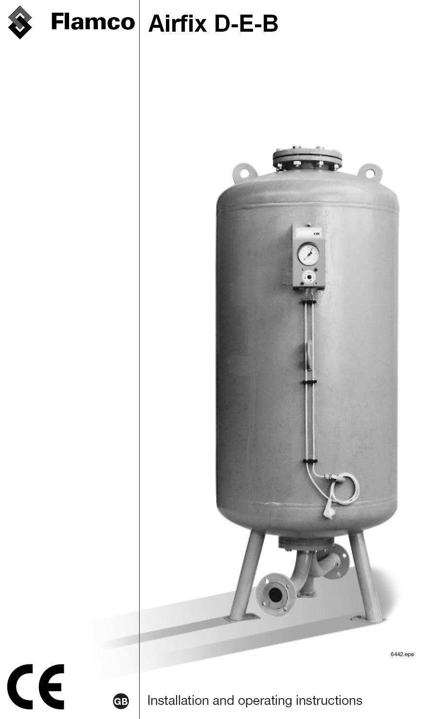
2 Airfix D-E-B Installation and operating instructions Dear Customer, With the Airfix D-E-B membrane expansion vessel you have acquired a Flamco quality product. This expansion vessel offers safe and reliable operation and simplicity of installation. In the following text you will find technical data, instructions and explanations to allow you to work properly and operate the equipment in safety. Anybody instructed to carry out work or other operations on this expansion vessel must read these installation and operating instructions carefully. We will be glad to answer any questions that cannot be clarified by the contents of this documentation. Additional technical information as well as supplemental details on special versions that we can provide is attached to this documentation as an appendix. General The Airfix D-E-B expansion vessel is a pressurised tank with a bladder diaphragm and adjustable gas admission pressure. It is intended for use in potable water systems and potable-water heating systems. To design the system, it is advisable to use the Flamco calculation disk for expansion vessels, which can be obtained on request from the Flamco Sales Office. Technical data, equipment The vessels are supplied as steel, upright models, painted on the outside and with a replaceable bladder. They are delivered on their side, packed on a non-returnable pallet. Specifications of vessel In compliance with DIN , the vessel is manufactured and tested as specified in the European Pressure Equipment directive (97/23/EC). The bladder meets the requirements of DIN and DIN Maximum operating pressure: 10 and 16 bar Maximum operating temperature: 70 C/343 K (vessel and bladder) Maximum water take-up capacity: 60% of nominal Maximum permissible gas admission pressure in the vessel's as delivered condition: 6 bar The high quality butyl rubber bladder material ensures a low degree of permeability (gas transfer) which can practically be ignored in the vessel's intended function.


3 1 Steel tank, externally painted in yellow-green 2 Butyl membranes, KTW-C/W270 3 Membrane mounting (600 litres and up, inside the vessel) 5 Inspection port (600 litres and up, top and bottom) 6 Pressure gauge with gas blow-back protection, vessel connection Rp3/8 DIN Gas filling valve, test connection 12 Model plate Method of operation The Airfix D-E-B diaphragm expansion vessel contains a gas chamber between the tank's inner surface and the membrane's outer surface as well as a water chamber inside the membrane. The gas chamber is adjusted to the required pressure in relation to the system specifications. A rise in pressure in the water chamber compresses the volume of gas and fills the membrane, whilst a reduction in pressure causes a water release. If the pressure in the gas chamber reaches the set water pressure in the system, water is drawn from the supply pipe. In this status, water passes through the vessel with a very low loss of pressure.
4 Use in potable water heating systems The vessel is installed in the cold water feed and takes up the heat expanded overflow volume. Drawing off water or a reduction in temperature leads to the water that has been taken up being released into the system. Use in pressure-boosting systems The vessel can be used both on the admission pressure and the ultimate pressure sides. These installations are intended to prevent unacceptable water hammer in the event of minimum flow speeds and minimum supply pressures not being reached. Operation on the admission pressure side The vessel is installed in the pump delivery line. It provides a supply of water to meet the demand and reduces the frequency for operating the pumps. Operation on the ultimate pressure side The vessel is installed in the pump delivery line. It provides a supply of water to meet the demand and reduces the frequency with which the pumps are engaged. Transport and storage Airfix D-E-B diaphragm expansion vessels are delivered on their side on a non-returnable pallet in fully assembled condition. Additional fittings may be packed separately. The vessel should be removed from its packing and placed where it is to be used. Fittings (lugs) on the vessel to take up the strain are only to be used for transporting empty, uninstalled (as delivered) tanks. The vessel can also be temporarily stored in its packing. The necessary conditions for this are: an enclosed, frost free and dry area, with no vibrations and protection from heat and sunlight. Vessels must not be stacked on top of each other!

 must be taken into account when constructing this surface. The vessel must be mounted vertically (perpendicularly).")
5 Assembly and installation Ambient conditions The membrane expansion vessels must be placed so that their operation, inspection and maintenance can constantly be ensured. The tanks must be set up in an enclosed, frost free area, observing the minimum distances shown in Table 4. The safe ambient temperature range for the vessel is 5-40 C. Table 4 Minimum distances Foundations and mounting The standing surface must be prepared so as to ensure that the vessel can stand on it securely and maintain an upright position. The max. operating weights in Table 5 (the complete vessel including water filling) must be taken into account when constructing this surface. The vessel must be mounted vertically (perpendicularly). Irrespective of the individual case, operation of the Airfix D-E-B litres in pressure-boosting systems and as a water hammer suppresser requires a mounting. If used for other applications, a mounting must be provided from and including 300 litres and upwards (see also Page 6). Details of available dimensions for the bottom connection are contained in Table 2. Avoid those types of mountings that would adversely affect the vessel. Do not, for example, set the container's feet in concrete or plaster, nor weld the vessel or its base, nor clamp or tension its base plate nor suspend it.
6 Installation The obligatory provisions for the relevant individual case and location apply. In addition, the following general rules for installation must be observed. The double system connection must be installed as a connection to the supply line. Ensure that this connection is made directly to the main potable water flow line. Standing surfaces with a uniform level are preferred if more than vessel is being used (to increase capacity). Prevent the permissible water take-up volume (60% of nominal volume) from being exceeded. Choose sealants and feed lines in accordance with the project but which at least cope with the max possible pressure and temperature values on this supply line. Fit a shut-off device directly in the vicinity of the system connection to ensure against un intentional closure. Install a filling and emptying device between the shut-off device and the system connection. When welding, prevent any weld metal from getting on or into the expansion vessel. If it is necessary to use a vessel with a gas admission pressure greater than 6 bar, this pressure this pressure must be established using nitrogen if there is a counter-pressure on the water lines side. When building up the gas admission pressure to above 6 bar the difference between the water and gas pressures should be a maximum of 3 bar. The top-up unit must be fitted with a suitable, tested safety valve. We would ask you to particularly take care that during assembly and dismantling as well as under special operating conditions (e.g. emptying the vessel) the difference between the gas admission pressure and the pressure at the system connection is not greater than 6 bar (e.g.: gas admission pressure 8 bar minus water pressure 2 bar equals 6 bar). If more than one vessel is being used and they are not arranged on the same level, the relevant static height for setting the gas admission pressure must be taken into account. Incorporation into potable water heating systems The expansion vessel must be fitted to the cold water line. If the potable water connection unit does not include a pressure reducer, this must be provided to ensure a constant steady pressure. The expansion vessel's admission pressure is adjusted by taking the admission/steady pressure behind the pressure reducer and subtracting 0.2 bar. If the pressure reducer and the expansion vessel are not on the same level, this must be taken into account accordingly.
7 Installation in pressure-boosting systems The regulations, in particular DIN ; -4; -5 and -6 governing potable water installations apply to this application. The details given by the pressurised system manufacturer should also be noted. Directly connected systems (where the pressure-boosting system is directly connected to the supply line branching off from the feeder line) require receivers as specified in DIN where expansion vessels are to be used on the admission pressure and ultimate pressure sides. Installation as a water hammer suppresser The regulations governing potable water installations apply to this application. The details given by the water hammer suppresser manufacturer should also be noted. The size and use of expansion vessels to reduce water hammer caused by rapid shut-off devices must be determined in accordance with the necessary system parameters and the device's characteristics. According to the requirements for suppression, the vessel's placement in the conduit system can be in the supply and/or the drain side. Commissioning The regulations for potable water installations apply. In addition, the following general rules on commissioning apply. (Note also the installation instructions) Check and set the necessary system pressure. Check the gas admission pressure, which was set according to the vessel's application and which must not exceed the maximum figure of 6 bar before the vessel is filled. Inspect the pressure limiting safety fittings for correct operation and reliability. Slowly open the supply valves for filling the vessel.

8 Maintenance, regular inspection Maintenance on the vessel should be carried out annually by a contract plumbing and heating firm. SCOPE OF THE MAINTENANCE: Checking the system pressure in relation to which the vessel's required gas admission pressure was determined. The pressure reducer should be adjusted as necessary. Checking the gas admission pressure and correcting it to the required value according to the project. Nitrogen should be used for raising the pressure and the top-up unit must be fitted with a suitable, tested safety valve. Note that this inspection requires the unit to be isolated via shut-off valves on the water side and complete drainage of the water chamber (no pressure on the vessel's water side). Also note the valve configuration as shown in Fig. 12. Leak test of the vessel's connections. 1 System connection and lower tank flange connection 2 Pressure gauge and filling valve connection 4 Membrane mounting (upper) and tank flange (upper) on Airfix D-E 600 litre models and above. Function test of the equipment items. Use Flamco approved spares or accessories. Prevent items delivered by Flamco from being rebuilt or modified at someone's own initiative. Check the item's exterior for damage and corrosion. Deformation or rust on pressurised components can cause unacceptable stresses or strains, with a possible consequence of components being destroyed and people being put at risk. We recommend that you use Flamco's Customer Service for your maintenance work. Regular inspection The fixed periods and scope of the inspection as laid down in the European Pressure Equipment Directive apply. For inspection operations, the works and acceptance certificate including the acceptance diagram are available to the operator. Airfix D-E-B applications in indirectly connected systems or other potable water systems. The scope of supply corresponds to the design specified in DIN (see Page 4, Technical Data), but with item 4 in a mono connection design instead of a double system connection. Table 6 contains the connection dimensions. 4 Mono system connection, internally coated as specified in DIN OPTION, a version in stainless steel

206-01-48, Краснодар")
268-04-70, Санкт-Петербург")
9 По вопросам продаж и поддержки обращайтесь: Екатеринбург (343) , Казань (843) , Краснодар (861) , Москва (495) , Санкт-Петербург (812) Единый адрес:
Flamco Airfix D-E. Installation and operating instructions. 1999, Flamco eps
 Airfix D-E 6442.eps GB Installation and operating instructions 1999, Exclusion of liability All operation and maintenance related technical information, data and instructions contained in these installation
Airfix. Flamco. Flamco. Pressure expansion vessels for sanitary appliances and potable water systems AIRFIX A AIRFIX D AIRFIX D-E
 AIRFIX EXPANSION VESSELS Flamco Airfix Pressure expansion vessels for sanitary appliances and potable water systems AIRFIX A AIRFIX AIRFIX -E Flamco Edition 2005 / EXP Flamco Flamco offers you a wide choice
Expansion Vessels for Potable Installations
 4. Expansion Vessels for Potable Installations Domestic installations lose millions of litres of potable water due to expansion water leaking from the vent and expansion pipe. Flamco s Airfix diaphragm
INDUSTRIAS IBAIONDO, HYDROPNEUMATIC TANKS
 IBAIONDO, HYDROPNEUMATIC TANKS IBAIONDO, INTRODUCTION Hydropneumatic tanks are designed to be used in potable water supply installations as a part of the pressure booster set in order to ensure the adequate
Airfix Pressure expansion vessels for sanitary appliances and potable water systems
 airfix expansion vessels Your reliable partner 4 Airfix Pressure expansion vessels for sanitary appliances and potable water systems AIRFIX A AIRFIX AIRFIX -E AIRFIX P Edition EXP 2009 Flamco offers you
Mounting and Operating Instructions EB 2558 EN. Self-operated Pressure Regulators. Type Pressure Build-up Regulator
 Self-operated Pressure Regulators Type 2357-31 Pressure Build-up Regulator with safety function and integrated excess pressure valve Type 2357-31 with non-return unit at port C Ports A and B with soldering
VESSELS. DIAPHRAGM OR BLADDER TANKS For expansion and pressure boosting applications. Temperature range : -10 to C* Operating pressure :
 operating limits Temperature range : -10 to + C* Operating pressure : to 20 bar* * according to models. VESSES IAPHRAGM OR BAER TANKS For expansion and pressure boosting applications AdVANTAGES APPICATIONS
Instruction Manual Contact Pressure Vacuum Gauge
 MS10 Instruction Manual Contact Pressure Vacuum Gauge Table of Contents 1. Safety Instructions 2. Intended Applications 3. Product Description and Functions 4. Installation 5. Commissioning 6. Maintenance
Replacement of Interchangeable Membrane
 Replacement of Interchangeable Membrane Replacement of Expansion Vessel Membrane 100+ Capacity 1. Firstly, before disconnecting the vessel, bear in mind that you must isolate the vessel from the system
Installation, Operation and Maintenance Instructions for Mild Steel Buffer Vessel
 OM006 Installation, Operation and Maintenance Instructions for Mild Steel Buffer Vessel The operating and maintenance instructions contained within this package are for standard mild steel buffer vessels
Self-operated Regulators Accessories Differential Pressure and Flow Regulators
 Self-operated Regulators Accessories Differential Pressure and Flow Regulators Compression-type fittings Needle valves Compensation chambers Orifice plates Welding neck flanges Control lines Application
Installation, Operation and Maintenance Instructions Buffer Vessel OM006
 Installation, Operation and Maintenance Instructions Buffer Vessel OM006 Calorifiers Heat Exchangers Pressurisation Units Sales Tel: 01457 835700 Sales Fax: 01457 832700 E-mail: sales@gmsthermal.co.uk
Installation, Operation and Maintenance Instructions for Pacific PA Non-Storage Heat Exchanger
 OM008 Installation, Operation and Maintenance Instructions for Pacific PA Non-Storage Heat Exchanger The operating and maintenance instructions contained within this package are for Pacific water/water
Self-operated Pressure Regulators for special applications
 Self-operated Pressure Regulators for special applications Type 2357-31 Pressure Build-up Regulator with safety function and integrated excess pressure valve Application Pressure regulators for cryogenic
Differential Pressure Regulator Type Type 45-6 (0.1 to 1 bar, DN 15) Mounting and Operating Instructions EB 3226 EN
 Mounting and Operating Instructions EB 3226 EN") Differential Pressure Regulator Type 45-6 Type 45-6 (0.1 to 1 bar, DN 15) Mounting and Operating Instructions EB 3226 EN Edition March 2008 Contents Contents Page 1 Design and principle of operation...................
Differential Pressure Regulator Type 45-6 Type 45-6 (0.1 to 1 bar, DN 15) Mounting and Operating Instructions EB 3226 EN Edition March 2008 Contents Contents Page 1 Design and principle of operation...................
Mainsboost Installation, Operation & Maintenance Instructions
 mainsboost Mainsboost Installation, Operation & Maintenance Instructions Please leave this instruction booklet with the home owner as it contains important guarantee, maintenance and safety information
MAINTENANCE AND OPERATING MANUAL
 MAINTENANCE AND OPERATING MANUAL Cyclone condensate separator Type ASA EN EN Maintenance and operating manual Purpose and appropriate use Dear Customer, thank you for choosing our product. In order to
TSS21 Sealed Thermostatic Steam Tracer Trap
 1255050/4 IM-P125-10 ST Issue 4 TSS21 Sealed Thermostatic Steam Tracer Trap Installation and Maintenance Instructions 1. Safety information 2. General product information 3. Installation 4. Commissioning
Horizontal Bladder Tanks
 DATA SHEET Horizontal Bladder Tanks Features UL Listed and FM Approved for use with various ANSUL proportioners and foam concentrates 175 psi (12.1 bar) maximum allowable working pressure (design pressure)
Датчики-реле давления GW A5 DUNGS
 По вопросам продаж и поддержки обращайтесь: Архангельск (88)6 90 7 Астана (77)77 Белгород (7)0 6 Брянск (8)9 0 Владивосток ()9 8 Волгоград (8)78 0 8 Вологда (87)6 9 Воронеж (7)0 7 Екатеринбург ()8 89 Иваново
Vertical Bladder Tanks
 DATA SHEET Vertical Bladder Tanks Features UL Listed and FM Approved for use with various ANSUL proportioners and foam concentrates 175 psi (12.1 bar) maximum allowable working pressure (design pressure)
Отсечные клапаны с электроприводом Burkert
 По вопросам продаж и поддержки обращайтесь: Архангельск (8182)63 90 72 Астана (7172)727 132 Белгород (4722)40 23 64 Брянск (4832)59 03 52 Владивосток (423)249 28 31 Волгоград (844)278 03 48 Вологда (8172)26
Installation, Operating and Maintenance Manual Overflow Regulator Type 94/ 94 E
 Installation, Operating and Maintenance Manual Overflow Regulator Type 94/ 94 E Table of content 1. General information on installation, operating and maintenance instructions 1.1 Hazard notices 1.2 Qualified
Blowdown vessels Meeting the requirements of HSE PM60
 Blowdown vessels Meeting the requirements of HSE PM60 BDV60 blowdown vessels A complete range of equipment for the safe disposal of boiler blowdown Boiler blowdown Steam boilers must be blown down to remove
Measurement accessories METPOINT OCV for the measurement in systems up to 40 bar
 EN - english Instructions for installation and operation Measurement accessories METPOINT OCV for the measurement in systems up to 40 bar Dear customer, Thank you for deciding in favour of the METPOINT
BT6HC Hygienic Sanitary Balanced Pressure Steam Trap for High Capacity and CIP/SIP Applications
 1800350/6 IM-P180-12 ST Issue 6 BT6HC Hygienic Sanitary Balanced Pressure Steam Trap for High Capacity and CIP/SIP Applications Installation and Maintenance Instructions 1. Safety information 2. General
Unit 24: Applications of Pneumatics and Hydraulics
 Unit 24: Applications of Pneumatics and Hydraulics Unit code: J/601/1496 QCF level: 4 Credit value: 15 OUTCOME 2 TUTORIAL 9 ACCUMULATORS The material needed for outcome 2 is very extensive so there are
Installation, Operation and Maintenance Instructions for Direct Hot Water Storage Vessels
 OM003 Installation, Operation and Maintenance Instructions for Direct Hot Water Storage Vessels The operating and maintenance instructions contained within this package are for standard storage vessels
Pressure Reducing Valve DMV 755
 Pressure Reducing Valve DMV 755 Nominal size DN 10 50 Nominal size 3/8 2 Nominal pressure PN 10 bar Features pressure setting range 1 to 9 bar control valve for reliable reduction of system pressures to
Model MTB-ASME Vertical Bladder Tanks
 DATA SHEET Model MTB-ASME Vertical Bladder Tanks Features n UL Listed for use with various proportioners and foam concentrates n 175 psi (12.1 bar) maximum allowable working pressure (design pressure)
Aquapresso. Pressure stabilisation for potable water Pressure stabilisation for potable water
 Aquapresso Pressure stabilisation for potable water Pressure stabilisation for potable water IMI PNEUMATEX / Pressure Maintenance and Control / Aquapresso Aquapresso Expansion vessels with fixed gas cushion
Application and Sizing
 Application and Sizing Energy accumulator: It is improbable that an hydraulic system use all of its capacity without interruptions. An hydropneumatic accumulator can store a certain amount of fluid that
FLUID POWER FLUID POWER EQUIPMENT TUTORIAL ACCUMULATORS. This work covers part of outcome 2 of the Edexcel standard module:
 FLUID POWER FLUID POWER EQUIPMENT TUTORIAL ACCUMULATORS This work covers part of outcome 2 of the Edexcel standard module: UNIT 21746P APPLIED PNEUMATICS AND HYDRAULICS The material needed for outcome
Installation, operation & maintenance manual - original version
 Installation, operation & maintenance manual - original version AVK gate valves for water and wastewater Series 01, 02, 06, 12, 15, 18, 20, 26, 32, 33, 36, 38, 50, 55 and 636 COPYRIGHT AVK GROUP A/S 2018
PV4 and PV6 Piston Valves
 1181250/1 IM-P118-05 ST Issue 1 PV4 and PV6 Piston Valves Installation and Maintenance Instructions 1. Safety information 2. General product information 3. Installation 4. Commissioning 5. Operation 6.
Model MTB-ASME Vertical Bladder Tanks
 DATA SHEET Model MTB-ASME Vertical Bladder Tanks Features n UL Listed for use with various proportioners and foam concentrates n 175 psi (12.1 bar) maximum allowable working pressure (design pressure)
Model MTB-ASME Horizontal Bladder Tanks
 DATA SHEET Model MTB-ASME Horizontal Bladder Tanks Features n UL Listed and FM Approved for use with various proportioners and foam concentrates n 175 psi (12.1 bar) maximum allowable working pressure
Mounting and Operating Instructions EB 3007 EN. Self-operated Pressure Regulators. Differential Pressure Regulators (opening) Type Type 42-25
 Type Type 42-25") Self-operated Pressure Regulators Differential Pressure Regulators (opening) Type 42-20 Type 42-25 Type 42-20 Differential Pressure Regulator Type 42-25 Differential Pressure Regulator Mounting and Operating
Self-operated Pressure Regulators Differential Pressure Regulators (opening) Type 42-20 Type 42-25 Type 42-20 Differential Pressure Regulator Type 42-25 Differential Pressure Regulator Mounting and Operating
Flexcon. Flamco. Flamco. Diaphragm pressure expansion vessels FLEXCON C 2-80 FLEXCON CE FLEXCON M FLEXCON V-B FLEXCON EXPANSION VESSELS
 FLEXCON EXPANSION VESSELS Flexcon Diaphragm pressure expansion vessels FLEXCON C 2-80 FLEXCON CE 110 1000 FLEXCON M FLEXCON V-B 2005 edition / EXP Choose quality choose a Flexcon the choice of a satisfied
multi-boost the EPS range of multi-boost water systems Owners Manual Installation Operation Maintenance demand special treatment
 multi-boost the EPS range of multi-boost water systems Owners Manual Installation Operation Maintenance demand special treatment Table of Contents Introduction... Health & Safety Health. Safety. Designs
Grundfos GT TANK Keep it safe
 GRUNDFOS GT TANK Grundfos GT TANK Keep it safe Long-life tanks for all needs Grundfos pressure tanks are all ideally suited and approved for use with drinking water. The material used ensures that there
UIB30 and UIB30H Sealed Inverted Bucket Steam Traps for use with Pipeline Connectors
 1130050/4 IM-P113-02 ST Issue 4 UIB30 and UIB30H Sealed Inverted Bucket Steam Traps for use with Pipeline Connectors Installation and Maintenance Instructions 1. Safety information 2. General product information
AVM7 Stainless Steel Thermostatic Air Vent
 1231850/4 IM-P123-23 ST Issue 4 AVM7 Stainless Steel Thermostatic Air Vent Installation and Maintenance Instructions 1. Safety information 2. General product information 3. Installation 4. Commissioning
Installation, Operation and Maintenance Instructions for Electronically Controlled Pressurisation Units
 Installation, Operation and Maintenance Instructions for Electronically Controlled Pressurisation Units Models: EPS Single Pump EPT Twin Pump EPS-HP EPT-HP Single Pump High Pressure Twin Pump High Pressure
BLADDER TANK PROPORTIONING SYSTEM PRE-PIPED
 BLADDER TANK PROPORTIONING SYSTEM PRE-PIPED HD FIRE PROTECT TECHNICAL DATA TANK MOUNTING Vertical or Horizontal TYPE COENTRATE For Vertical Tank 140 liters STORAGE CAPACITY to7500 liters (36 TO 2000 Gallon
Mounting and Operating Instructions EB 3009 EN. Self-operated Regulators. Type RS Check Valve (backflow protection)
") Self-operated Regulators Type 42-10 RS Check Valve (backflow protection) Type 42-10 RS Check Valve (backflow protection) Mounting and Operating Instructions EB 3009 EN Edition December 2015 Definition
Self-operated Regulators Type 42-10 RS Check Valve (backflow protection) Type 42-10 RS Check Valve (backflow protection) Mounting and Operating Instructions EB 3009 EN Edition December 2015 Definition
CAST IRON SAFETY VALVE TYPE 6301
 CHARACTERISTICS The 6301 safety valve is dedicated to protect the equipment from potential overpressure. This is an automatic device that closes when the pressure conditions are back to normal. It is a
System Pressure Manager Standard & System Pressure Manager Plus
 System Pressure Manager Standard & System Pressure Manager Plus Installation, Commissioning & Servicing Instructions Note: THESE INSTRUCTIONS MUST BE READ AND UNDERSTOOD BEFORE INSTALLING, COMMISSIONING,
Pressure Reducing Valve for Steam Type 2333 A
 Pressure Reducing Valve for Steam Type 2333 A Fig. 1 Type 2333 A 1. Design and principle of operation The pressure reducing valve consists of a balanced control valve and a closing actuator equipped with
MST21 Stainless Steel Balanced Pressure Thermostatic Steam Trap
 1250650/6 IM-P125-07 ST Issue 6 MST21 Stainless Steel Balanced Pressure Thermostatic Steam Trap Installation and Maintenance Instructions 1. Safety information 2. General product information 3. Installation
Mounting and Operating Instructions EB 2555 EN. Self-operated Pressure Regulators. Pressure Reducing Valves Type 50 ES Type 50 EM.
 Self-operated Pressure Regulators Pressure Reducing Valves Type 50 ES Type 50 EM Type 50 ES Type 50 EM Fig. 1 Pressure reducing valves Mounting and Operating Instructions EB 2555 EN Edition November 2011
ECONORESS ELECTRONIC EPS & EPT - ENHANCED PRESSURISATION SET INSTALLATION OPERATION & MAINTENANCE DOCUMENTATION
 ECONORESS ELECTRONIC EPS & EPT - ENHANCED PRESSURISATION SET INSTALLATION OPERATION & MAINTENANCE DOCUMENTATION OCT2010 STOKVIS ENERGY SYSTEMS 96R WALTON ROAD EAST MOLESEY SURREY KT8 0DL TEL: 020 87833050
Accessories for Sanitary Installations
 5. Accessories for Sanitary Installations Flamco s Prescor B safety valves protect potable water systems from exceeding the maximum design operating pressure. Once the set pressure has been reached the
USM21 Sealed Bimetallic Steam Trap for use with Pipeline Connectors Installation and Maintenance Instructions
 6250250/1 IM-P625-03 ST Issue 1 USM21 Sealed Bimetallic Steam Trap for use with Pipeline Connectors Installation and Maintenance Instructions 1. General safety information 2. General product information
Dri-Line Mk3 Monnier Compressed Air Drain Trap
 5044050/2 IM-P504-24 CH Issue 2 Dri-Line Mk3 Monnier Compressed Air Drain Trap Installation and Maintenance Instructions 1. Safety information 2. General product information 3. Installation and Operation
Translation of the original Operating Instructions for HKS rubber compensators
 Because of their flexible elements and mechanisms, HKS rubber compensators are susceptible to damage of all types and adverse loads in operation. For reliable operation of a compensator and, thus, the
Easy-Pro Installation & Operations Guide
 Easy-Pro Installation & Operations Guide Installation & Maintenance Guide Operation The EASY-PRO range of Expansion Vessels is specifically designed for Unvented Potable Systems to deal with increased
Pressure surge absorption
 Pressure surge absorption Product range for drinking water, waste water and the chemical industry With remote monitoring, everything is fully under control. Willy Zahnd, WARET AG PRESSURE SURGE ABSORPTION
VERTICAL BLADDER TANK
 Balanced Pressure Proportioning System Reliable Foam System Requiring Only Water Power Perfect For Tight Spaces UL Listed, ASME, National Board Registered Bladder-UL162 Approved, High Tensile Pressure
Series 42 Self-operated Regulators Differential Pressure Regulators with Type 2424/Type 2428 Actuator (closing) Type Type 42-28
 Type Type 42-28") Series 42 Self-operated Regulators Differential Pressure Regulators with Type 2424/Type 2428 Actuator (closing) and balanced Type 2422 Valve Type 42-24 Type 42-28 Application Differential pressure regulators
Series 42 Self-operated Regulators Differential Pressure Regulators with Type 2424/Type 2428 Actuator (closing) and balanced Type 2422 Valve Type 42-24 Type 42-28 Application Differential pressure regulators
TA10A and TA10P Steam Tracing Temperature Control Valves Installation and Maintenance Instructions
 3500032/2 IM-P350-02 CH Issue 2 TA10A and TA10P Steam Tracing Temperature Control Valves Installation and Maintenance Instructions 1. Safety information 2. General product information 3. Installation 4.
KBV21i and KBV40i Key Operated Boiler Blowdown Valves Installation and Maintenance Instructions
 4059051/3 IM-P405-48 EMM Issue 3 KBV21i and KBV40i Key Operated Boiler Blowdown Valves Installation and Maintenance Instructions 1. Safety information 2. General product information 3. Installation 4.
INSTALLATION, OPERATION AND MAINTENANCE MANUAL. Model Sanitary Vent SECTION I
 INSTALLATION, OPERATION AND MAINTENANCE MANUAL Model 1100 Sanitary Vent IOM-1100 03-17 ISO Registered Company SECTION I I. DESCRIPTION AND SCOPE The Model 1100 is a stainless steel sanitary vent designed
Expansion Tank Design (Chilled Water)
") Expansion Tank Design (Chilled Water) Table of Contents 1.0 Introduction... 2 1.1 Units... 2 2.0 Disclaimer... 2 3.0 Expansion Tank Types... 2 3.1 Open Tank... 2 3.2 Closed Tank with No Bladder... 3 3.3
Expansion Tank Design (Chilled Water) Table of Contents 1.0 Introduction... 2 1.1 Units... 2 2.0 Disclaimer... 2 3.0 Expansion Tank Types... 2 3.1 Open Tank... 2 3.2 Closed Tank with No Bladder... 3 3.3
HM and HM34 Inverted Bucket Steam Traps Installation and Maintenance Instructions
 0670350/4 IM-S03-11 ST Issue 4 HM and HM34 Inverted Bucket Steam Traps Installation and Maintenance Instructions 1. Safety information 2. General product information HM Series 3. Installation 4. Commissioning
Spilt body Flange ball valve. TC-205MFF-PN1640 User Manual English Version. Document No: TC-205MFF-PN1640.Ur-manual. Date: 2007/04/2617. Version: 1.
 Spilt body Flange ball valve TC-205MFF-PN1640 Series PED Category I,II TC-205MFF-PN1640 User Manual English Version Use for company in Europe who will place the product on the market, please amend which
Manual Actuated Boiler Blowdown Valves
 Manual Actuated Boiler Blowdown Valves Installation and Maintenance Instructions 1. Safety information 2. General product information 3. Installation 4. Operation 5. Maintenance 6. Spare parts p.1 1. Safety
GENERAL SAFETY INSTRUCTION GSI-M-2 STANDARD PRESSURE EQUIPMENT
 GENERAL SAFETY INSTRUCTION GSI-M-2 STANDARD PRESSURE EQUIPMENT Publication date: 09-06-2015 All CERN Safety Rules are available on the web site: https://www.cern.ch/safety-rules Page 1 of 8 1 INTRODUCTION
Operating instruction
 Operating instruction MV, XV, HG, HP, RKO, D2G, TV, BV, WB & SLV 1 Introduction 2 2 Stafsjö s knife gate valves 2 3 Technical information 2 3.1 Pressure test 2 3.2 Labelling 2 4 Storage 3 5 Transportation
HORIZONTAL BLADDER TANK
 Balanced Pressure Proportioning System Reliable Foam System Requiring Only Water Power Perfect For Low Ceilings UL Listed, ASME, National Board Registered Bladder-UL162 Approved, High Tensile Pressure
BIMBAR INFLATABLE PACKERS AND ACCESSORIES
 BIMBAR INFLATABLE PACKERS AND ACCESSORIES Geopro supplies a complete range of inflatable packers in nine different diameters from 28 up to 170mm. All our packers made of BIMBAR rubber technology are reinforced
Automatic balancing valves ASV
 Automatic balancing valves ASV ASV-P ASV-PV ASV-PV ASV-PV ASV-I ASV-M 15-40 15-40 50 65-100 15-50 15-50 Description / Application ASV balancing valves are used for dynamic hydronic balance in heating and
Differential pressure and flow controller (PN 16) AVPQ - return mounting, adjustable setting
 AVPQ - return mounting, adjustable setting") Data sheet Differential pressure and flow controller (PN 16) AVPQ - return mounting, adjustable setting Description AVPQ is a self-acting differential pressure and flow controller primarily for use in
Data sheet Differential pressure and flow controller (PN 16) AVPQ - return mounting, adjustable setting Description AVPQ is a self-acting differential pressure and flow controller primarily for use in
Instruction Manual Contact Pressure Gauge
 MS11 Instruction Manual Contact Pressure Gauge Table of Contents 1. Safety Instructions 2. Intended Applications 3. Product Description and Functions 4. Installation 5. Commissioning 6. Maintenance 7.
94270 Vapor Guard Tank Blanketing Valve Vapor Guard Tank Blanketing Valve What is Tank Blanketing? Features How does it work?
 94270 What is Tank Blanketing? blanketing systems are used to prevent the escape of liquid vapors into the atmosphere or to prevent moisture from entering a tank and contaminating its contents. A tank
BTM7, BTS7 and BTS7.1 Stainless Steel Thermostatic Clean Steam Traps
 1801050/10 IM-P180-05 ST Issue 10 BTM7, BTS7 and BTS7.1 Stainless Steel Thermostatic Clean Steam Traps Installation and Maintenance Instructions 1. Safety information 2. General product information 3.
DECLARATION OF INCORPORATION
 AESSEAL (MCK) Ltd. Systems Division 139a Hillsborough Old Road Lisburn Northern Ireland BT27 5QE Tel +44 (0) 2892 669966 Fax +44 (0) 2892 669977 When selecting and installing suitable Barrier Fluid System
Art PRESSURE REDUCER
 FUNCTION ICMA pressure reducers are devices that reduce and stabilize the incoming pressure from the water supply. Pressure reducers allow correct use on domestic systems, reducing malfunctions due to
AVP-F. p setting range (bar) Code No. 003H6200
 Code No. 003H6200") Data sheet Differential pressure controller (PN 16) AVP - return and flow mounting, adjustable setting AVP-F - return mounting, fixed setting Description The controller has a control valve, an actuator
Data sheet Differential pressure controller (PN 16) AVP - return and flow mounting, adjustable setting AVP-F - return mounting, fixed setting Description The controller has a control valve, an actuator
Pressure relief valve DHV 712 DN 65-80: 0,5-10 bar, DN : 0,3-4 bar, DN 100: 0,5-6 bar
 Pressure relief valve DHV 7 DN 5-80: 0,5-0 bar, DN 5-00: 0, - bar, DN 00: 0,5 - bar Advantage for high pressure stability reliable reduction of pressure peaks and pulsations pressure setting possible at
Diaphragm Accumulators
 1. DESCRIPTION 1.1. FUNCTION Fluids are practically incompressible and cannot therefore store pressure energy. The compressibility of a gas is utilised in hydro-pneumatic accumulators for storing fluids.
Instruction Manual Differential Pressure Transmitter
 DE13 Instruction Manual Differential Pressure Transmitter Table of Contents 1. Safety Instructions 2. Intended Applications 3. Product Description and Functions 4. Installation 5. Commissioning 6. Maintenance
Pressure Relief Valve DHV 718
 Advantages frictionless components low maintenance low pressure increase up to fully opened valve constant low vibration controlling hermetically sealed by diaphragm for oscillating pumps for viscous media
Mounting and Operating Instructions EB EN. Self-operated Pressure Regulators. Type 2335 Excess Pressure Valve with pilot valve
 Self-operated Pressure Regulators Type 2335 Excess Pressure Valve with pilot valve Type 2335 Excess Pressure Valve Mounting and Operating Instructions EB 2552-2 EN Edition January 2016 Definition of signal
Hand pump type CH. Product documentation. 300 bar 8.3 cm 3 /stroke. Operating pressure p max : Displacement volume V max stroke :
 Hand pump type CH Product documentation Operating pressure p max : Displacement volume V max stroke : 300 bar 8.3 cm 3 /stroke D 7147 CH 04-2018-1.1 by HAWE Hydraulik SE. The reproduction and distribution
Declaration of Conformity as per Directive 97/23/EC
 Declaration of Conformity as per Directive 97/23/EC The manufacturer declares that:, 47906 Kempen, Germany Continuous, inline sampling valves Series 27f, with packing Operate with either; Star lever, or
TECHNICAL DATA. Q = C v P S
 Page 1 of 13 1. DESCRIPTION The Viking 6 Model G-6000 Dry Valve Riser Assembly consists of a small profile, light weight, pilot operated valve that is used to separate the water supply from the dry sprinkler
WATER HEATER THERMAL EXPANSION TANKS Owner s Manual. Safety Instructions Installation Maintenance Warranty. Models: 2-5 Gallon Capacity
 WATER HEATER THERMAL EXPANSION TANKS Owner s Manual Safety Instructions Installation Maintenance Warranty Models: 2-5 Gallon Capacity Thank You for purchasing this Thermal Expansion Tank. Properly installed
HAYWARD FLOW CONTROL Series PBV Back Pressure Valve and Series RPV Pressure Relief Valve INSTALLATION, OPERATION, AND MAINTENANCE INSTRUCTIONS
 HAYWARD FLOW CONTROL Series PBV Back Pressure Valve and Series RPV Pressure Relief Valve INSTALLATION, OPERATION, AND MAINTENANCE INSTRUCTIONS Page 1 of 20 Page 2 of 20 TABLE OF CONTENTS Safety Warnings
PumpAgents.com - Click here for Pricing/Ordering Nominal psi (bar) Cut-In Cut-Out
 Cut-In Cut-Out") PumpAgents.com - Click here for Pricing/Ordering Model 31670-Series Dual Max 7.5 GPM (28 LPM) AUTOMATIC TWO STAGE WATER SYSTEM WITH ACCUMULATOR TANK AND PUMPGARD STRAINER IDEAL FOR PLEASURE AND COMMERCIAL
PumpAgents.com - Click here for Pricing/Ordering Model 31670-Series Dual Max 7.5 GPM (28 LPM) AUTOMATIC TWO STAGE WATER SYSTEM WITH ACCUMULATOR TANK AND PUMPGARD STRAINER IDEAL FOR PLEASURE AND COMMERCIAL
USER MANUAL. 1. Principle of operation. 2. Delivery condition. SPRING-LOADED SAFETY VALVES zarmak. Edition: 07/2016 Date: V (ex.
 ZETKAMA Sp. z o.o. ul. 3 Maja 12 PL 57-410 Ścinawka Średnia SPRING-LOADED SAFETY VALVES zarmak USER MANUAL 782V (ex. 782) Edition: 07/2016 Date: 01.07.2016 TABLE OF CONTENTS 1. Principle of operation 2.
Exhibit 4. Determination of Static Pressure Performance of the Healy Clean Air Separator (Executive Orders VR-201-N and VR-202-N)
") 1 APPLICABILITY Exhibit 4 Determination of Static Pressure Performance of the Healy Clean Air Separator (Executive Orders VR-201-N and VR-202-N) Definitions common to all certification and test procedures
1 APPLICABILITY Exhibit 4 Determination of Static Pressure Performance of the Healy Clean Air Separator (Executive Orders VR-201-N and VR-202-N) Definitions common to all certification and test procedures
AE14 Automatic Air Vents for Liquid Systems Installation and Maintenance Instructions
 1490050/7 IM-P149-06 CMGT Issue 7 AE14 Automatic Air Vents for Liquid Systems Installation and Maintenance Instructions 1. General safety information 2. General product information 3. Installation 4. Commissioning
ACCUMULATOR OPERATING & MAINTENANCE INSTRUCTIONS
 ACCUMULATOR OPERATING & MAINTENANCE INSTRUCTIONS READ ALL INSTRUCTIONS PRIOR TO INSTALLATION AND OPERATION TO AVOID POSSIBLE INJURY Warning: Always consider any accumulator to contain pressure until proven
Two-port valves, male threaded, PN25
 4 379 Two-port valves, male threaded, PN25 VVG55... Two-port valves, externally threaded, PN25 Bronze Rg5 DN15... 25 mm (½"... 1") k vs 0.25... 6.3 m 3 /h Stroke 5.5 mm Suitable for type SQS35... or SQS65...
ANNEX AMENDMENTS TO THE INTERNATIONAL CODE FOR FIRE SAFETY SYSTEMS (FSS CODE) CHAPTER 15 INERT GAS SYSTEMS
 CHAPTER 15 INERT GAS SYSTEMS") Annex 3, page 2 ANNEX AMENDMENTS TO THE INTERNATIONAL CODE FOR FIRE SAFETY SYSTEMS (FSS CODE) CHAPTER 15 INERT GAS SYSTEMS The text of existing chapter 15 is replaced by the following: "1 Application This
Annex 3, page 2 ANNEX AMENDMENTS TO THE INTERNATIONAL CODE FOR FIRE SAFETY SYSTEMS (FSS CODE) CHAPTER 15 INERT GAS SYSTEMS The text of existing chapter 15 is replaced by the following: "1 Application This
TECHNICAL DATA 3 MODEL G-3000 DRY VALVE RISER ASSEMBLY
 Page 1 of 13 1. DESCRIPTION The Viking 3 Model G-3000 Dry Valve Riser Assembly is equipped with a small profile, light weight, pilot operated valve that is used to separate the water supply from the dry
Ball valve HKSF-W100. Ball valve HKSF-W100. RMA Kehl GmbH & Co. KG Oststrasse 17 D Kehl / Germany
 Ball valve HKSF-W100 RMA Kehl GmbH & Co. KG Oststrasse 17 D-77694 Kehl / Germany info@rma-kehl.de www.rma-armaturen.de 1 Design Features: RMA-ball valves type HKSF-W are fully welded and completely maintenance-free
Installation, Operating, Maintenance and Safety Instructions for. Pressurised water systems for boats
 FLOMAX-SYSTEM DOC532/11 Installation, Operating, Maintenance and Safety Instructions for FLOMAX-SYSTEM Pressurised water systems for boats CW343A FloMax System 12 volt d.c. CW344A FloMax System 24 volt
FV Flash Vessel Installation and Maintenance Instructions
 4041050/5 IM-P404-10 EMM Issue 5 FV Flash Vessel Installation and Maintenance Instructions 1. Safety information 2. Specific product safety information 3. Product information 4. Installation 5. Commissioning