Hydraulics. Hydraulic Pressure Control
|
|
|
- Branden Sullivan
- 5 years ago
- Views:
Transcription

1 Hydraulics Hydraulic Pressure Control


2 Direct Acting Pressure Relief Valve Normally Closed:
 Small pilot relief valve + Main relief")
3 Pilot Operated Relief Valve (Compound/ two stage) Small pilot relief valve + Main relief valve

4 Pilot Operated Relief Valve (Compound/ two stage)

5 Pilot Operated Relief Valve (Compound/ two stage)

6 Pilot Operated Relief Valve with remote control


7 Pilot Operated Relief Valve with remote control Whenever pump flow and pressure are not needed:

8 Pressure Override: Pressure Override= Full-flow pressure - cracking pressure

9

10 Cross-over Pressure Relief Valve Preventing shifting shock in motor Provides a shock absorbing or cushioning effect

11 Unloading Valve: An unloading valve reads the pressure in an external line, rather than in its own line Both relief and unloading valves send flow back to the tank

12 Unloading Valve Circuit:
13 Unloading Valve Circuit: Example: metal stamping machine High flow (speed)-low pressure (force) in a part of the stroke Low flow (speed)- high pressure (force) in another part of the stroke
14 Unloading Valve Circuit:
 The relief valve reads the pressure upstream( before the valve) Normally close Normally")
15 Pressure Reducing Valve: Maintain a reduced pressure level in a branch circuit of a hydraulic system The reducing valve reads the pressure downstream( after the valve) The relief valve reads the pressure upstream( before the valve) Normally close Normally open

16 Pressure Reducing Valve Application: Energy loss Heat Generation

17 Sequence Valve: Sequence valve is a pressure valve that is used to force two actuators to be operated in sequence Instead of sending flow back to the tank, a sequence valve allows flow to a branch circuit when a present pressure is reached

18 Sequence Valve Application: A clamp cylinder extends first to hold a work piece, then a second cylinder extends to bend the work piece into a desired shape


19 Sequence Valve Application: Setting by trial and error

20 Sequence Valve Application: Both cylinders retracting

21 Sequence Valve Application: The bending cylinder will extend only after the clamp cylinder is fully extended and the clamp cylinder will retract only after the bending cylinder is fully retracted

22 Counterbalance Valves: Counterbalance valves are pressure control valves that are used to prevent a load from accelerating uncontrollably

23 Counterbalance Valves: When the DCV is shifted to lower the weight, the cylinder will not extend until a preset pressure is reached in the rod end The check valve allows the counterbalance valve to be bypassed when the cylinder is retracted Sequence valve requires an external drain, while a counterbalance valve does not because it can be drained internally Setting by trial and error
 (motor acting as a")
24 Brake Valves: Like counterbalance valves are used to prevent load from accelerating uncontrollably counterbalance valves are used with cylinders; brake valves are used with hydraulic motors Commonly used in circuits in which the motor must lower a large weight When the weight is lowered, it may tend to drive the motor, instead of the motor lowering the weight (overrunning) (motor acting as a pump!!!!!) Sensing the pressure at both sides A simple winch circuit

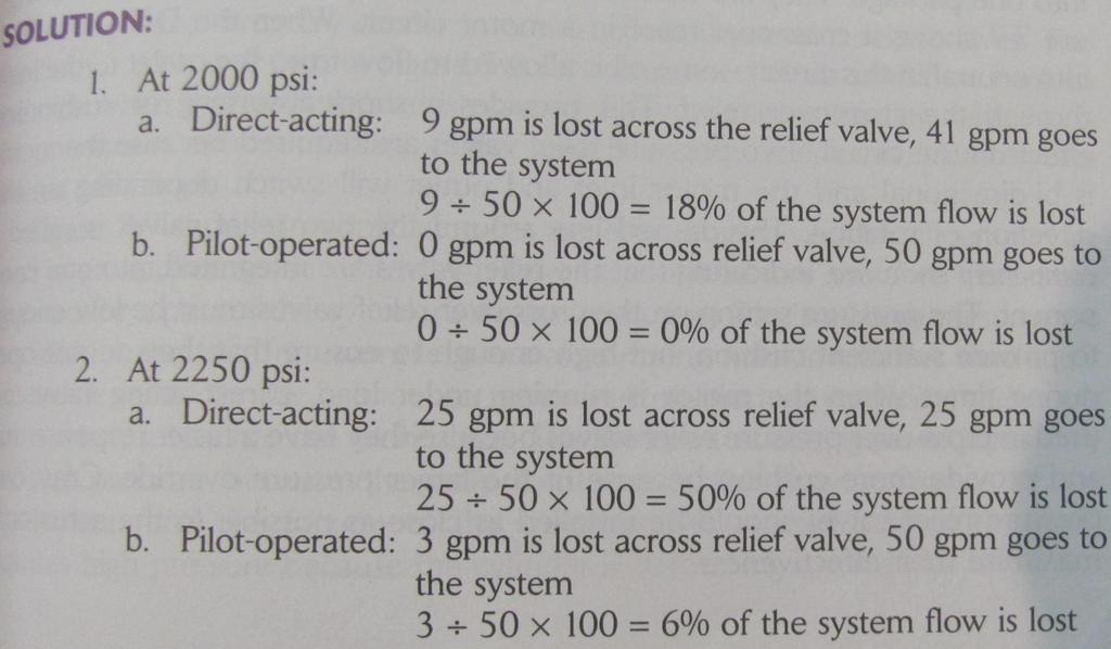
25 Pressure-compensated Pumps: Have the ability to limit the maximum pressure in a hydraulic circuit by reducing their displacement Decreasing due to leakage

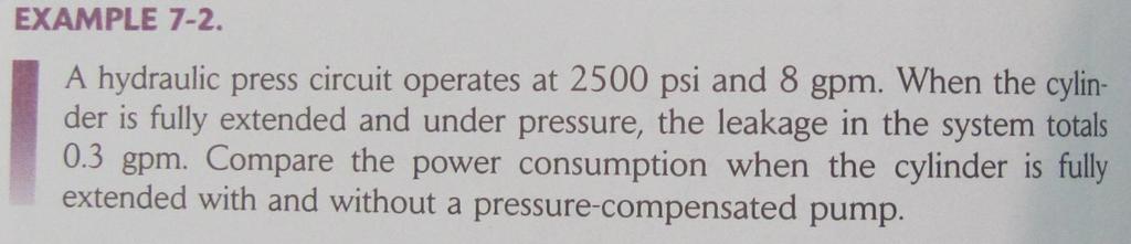
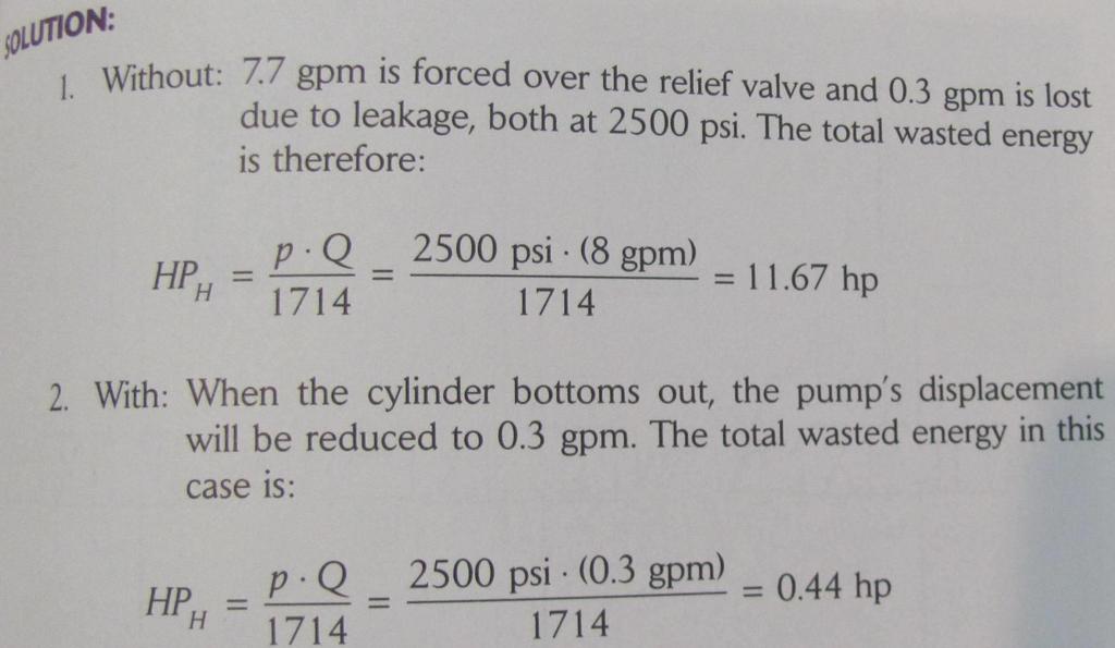
26 Pressure-compensated Pumps: Hydraulic press circuit Pressure must be maintained for a period of time The valve could not go to the neural due to leakage and then pressure drop Heat generation

27 Pressure-compensated Pumps: Hydraulic press circuit Rule of thumb: pressure relief valve 10% higher than the compensator setting
28
[You may download this article at: https://fluidsys.org/downloads/ ]
![[You may download this article at: https://fluidsys.org/downloads/ ]](/thumbs/77/76410234.jpg "[You may download this article at: https://fluidsys.org/downloads/ ]") Fluidsys Training Centre, angalore offers an extensive range of skill-based and industry-relevant courses in the field of Pneumatics and Hydraulics. For more details, please visit the website: https://fluidsys.org
Fluidsys Training Centre, angalore offers an extensive range of skill-based and industry-relevant courses in the field of Pneumatics and Hydraulics. For more details, please visit the website: https://fluidsys.org
Lecture 19 PRESSURE-CONTROL VALVES [CONTINUED]
![Lecture 19 PRESSURE-CONTROL VALVES [CONTINUED]](/thumbs/76/73283391.jpg "Lecture 19 PRESSURE-CONTROL VALVES [CONTINUED]") Lecture 19 PRESSURE-CONTROL VLVES [CONTINUED] 1.5 Counterbalance Valve Schematic diagram of counterbalance valve is shown in Fig. 1.14. These normally closed valves are primarily used to maintain a back
Lecture 19 PRESSURE-CONTROL VLVES [CONTINUED] 1.5 Counterbalance Valve Schematic diagram of counterbalance valve is shown in Fig. 1.14. These normally closed valves are primarily used to maintain a back
Contents. Catalog HY /US Load and Motor Control Valves SERIES CAVITY DESCRIPTION FLOW PRESSURE PAGE NO. LPM/GPM BAR/PSI
 Load and Motor Control Contents SERIES CAVITY DESCRIPTION FLOW PRESSURE PAGE NO. LPM/GPM BAR/PSI STANDARD PILOT ASSISTED CB101... C10-3... Load Control Cartridge Valve...45/12... 380/5500... 5-6 MHC-010-S***
Introduction. Part one: Identify the Hydraulic Trainer Components
 The University Of Jordan School of Engineering Mechatronics Engineering Department Fluid Power Engineering Lab Experiments No.4 Introduction to Hydraulic Trainer Objective: Students will be able to identify
Copyright, 2005 GPM Hydraulic Consulting, Inc.
 Troubleshooting and Preventive Maintenance of Hydraulic Systems Learning to Read the Signs of Future System Failures Instructed by: Al Smiley & Alan Dellinger Copyright, 2005 GPM Hydraulic Consulting,
Tech Tips. Service Call: Adjustable Hydraulic Valves Flow controls Pressure controls Sequence valves Holding valves
 Service Call: Adjustable Hydraulic Valves Flow controls Pressure controls Sequence valves Holding valves Tools Required: Flow Meter Pressure gauge Holding valve test block Wrenches for installation of
ANTI SHOCK RELIEF VALVE
 ANTI SHOCK RELIEF VALVE Wheeler Road Coventry CV3 4LA England Brüsseler Allee 2 D-41812 Erkelenz Tel. +44(0)2476-217-400 Fax +44(0)2476-217-488 Tel. +49(0)24 31-80 91-0 Fax +49(0)24 31-80 91-19 www.sunhydraulics.com
FLUID POWER FLUID POWER EQUIPMENT TUTORIAL OTHER FLUID POWER VALVES. This work covers part of outcome 2 of the Edexcel standard module:
 FLUID POWER FLUID POWER EQUIPMENT TUTORIAL OTHER FLUID POWER VALVES This work covers part of outcome 2 of the Edexcel standard module: UNIT 21746P APPLIED PNEUMATICS AND HYDRAULICS The material needed
Time-Delay Electropneumatic Applications
 Exercise 3-4 EXERCISE OBJECTIVE & & & To introduce time delays; To describe the operation of a time-delay valve; To describe the operation of a time-delay relay. DISCUSSION Time-Delays Time delays are
Priority (Swing) Motors Data and Specifications
 Motors Data and Specifications") s Data and Specifications Specifications HMF 55 HMF 75 HMF 105 cm 3/rev in 3/rev 55 3.36 75 4.57 105 6.40 Pressure Ratings Nominal 5000 PSIG Maximum 6090 PSIG Peak 7250 PSIG Operating Speed Maximum 4100
s Data and Specifications Specifications HMF 55 HMF 75 HMF 105 cm 3/rev in 3/rev 55 3.36 75 4.57 105 6.40 Pressure Ratings Nominal 5000 PSIG Maximum 6090 PSIG Peak 7250 PSIG Operating Speed Maximum 4100
MWEA MAINTENANCE SEMINAR SPECIALTY VALVES POWER GLOBES
 MWEA MAINTENANCE SEMINAR SPECIALTY VALVES POWER GLOBES J O H N G. H U N T E R Types of Valves P A U L M A R C H I Accessories Principals of Operation Maintenance Control Valve Types Common Problems Key
Xpress L90LS Directional Control Valve. Catalog HY /UK December, 2001
 Xpress L90LS Directional Control Valve Catalog HY17-8525/UK December, 2001 Catalogue HY17-8525/UK Technical Information Xpress - general information Xpress is a valve-customization service that enables
LECTURE 20 FLOW CONTROL VAVLES SELF EVALUATION QUESTIONS AND ANSWERS
 LECTURE 20 FLOW CONTROL VAVLES SELF EVALUATION QUESTIONS AND ANSWERS 1: A cylinder has to exert a forward thrust of 150 kn and a reverse thrust of 15 kn. The effects of using various methods of regulating
MADILL 24.7" 365 TILT SET-UP PROCEDURE WITH REXROTH VALVE ON MACHINE
 MADILL 24.7" 365 TILT SET-UP PROCEDURE WITH REXROTH VALVE ON MACHINE MADILL 24.7" SAW - 365 DEG. TILT-REXROTH VALVE DANGER DO NOT perform any adjustment on sawhead unless saw blade lock bolt and guard
Lesson 6: Flow Control Valves
 : Flow Control Valves Basic Hydraulic Systems Hydraulic Fluids Hydraulic Tank Hydraulic Pumps and Motors Pressure Control Valves Directional Control Valves Flow Control Valves Cylinders : Flow Control
Load Controls Screw In Cartridge Valves Pressures to 350 bar (5000 psi) Flows to 190 l/min (50 USgpm)
 Flows to 190 l/min (50 USgpm)") Vickers Cartridge Valves Load Controls Screw In Cartridge Valves Pressures to 50 bar (5000 psi) Flows to 90 l/min (50 USgpm) Rev. 2/99 722 Contents MODEL DESCRIPTION TYP. APPLICATION PRESSURE bar (psi)
Vickers Cartridge Valves Load Controls Screw In Cartridge Valves Pressures to 50 bar (5000 psi) Flows to 90 l/min (50 USgpm) Rev. 2/99 722 Contents MODEL DESCRIPTION TYP. APPLICATION PRESSURE bar (psi)
Directional Control valves
 Chapter 10.1 Chapter 10 Directional Control valves 10.1 Check Valves Figure 10.1 Check valve wo conditions: free flow or "checked" flow Usually has a cracking pressure of 69 a 104 a (10-15 psi) If used
INDIAN INSTITUTE OF TECHNOLOGY KHARAGPUR NPTEL ONLINE CERTIFICATION COURSE. On Industrial Automation and Control
 INDIAN INSTITUTE OF TECHNOLOGY KHARAGPUR NPTEL ONLINE CERTIFICATION COURSE On Industrial Automation and Control By Prof. S. Mukhopadhyay Department of Electrical Engineering IIT Kharagpur Topic Lecture
Exercise 2-3. Flow Rate and Velocity EXERCISE OBJECTIVE C C C
 Exercise 2-3 EXERCISE OBJECTIVE C C C To describe the operation of a flow control valve; To establish the relationship between flow rate and velocity; To operate meter-in, meter-out, and bypass flow control
Cartridge Valves Technical Information. Pilot operated check valves. Quick reference
 Quick reference Pilot to Open Model No. Description Flow* Pressure Page P RPC 4 NCS4/ Pilot Operated Check Valve, Pilot to Open l/min [ US gal/min] RPC 6 NCS6/ 5 l/min [7 US gal/min] CP45- SDC- l/min RPC
Technical Tip. LoadAdaptive TM Counterbalance Valves. Introduction. Overview. November2015
 November2015 CORPORATION Technical Tip LoadAdaptive TM Counterbalance Valves Introduction Sun Hydraulics patent-pending LoadAdaptive TM counterbalance valves use a novel mechanical design to allow variable
Directional Controls
 Vickers Directional Controls CMX System Start Up & Trouble Shooting Guide Released 12/92 592 Table of Contents Introduction......................................................................................
(Refer Slide Time: 0:26)
") Fundamentals of Industrial Oil Hydraulics and Pneumatics By Professor R. Maiti Department of Mechanical Engineering Indian Institute of Technology, Kharagpur Module03 Lecture08 Different Types of Valves-
Fundamentals of Industrial Oil Hydraulics and Pneumatics By Professor R. Maiti Department of Mechanical Engineering Indian Institute of Technology, Kharagpur Module03 Lecture08 Different Types of Valves-
Basic Hydraulics. Module 4: Flow Control Valves & Pressure Relief Valves. Academic Services PREPARED BY. January 2012
 Basic Hydraulics Module 4: Flow Control Valves & Pressure Relief Valves PREPARED BY Academic Services January 2012 Applied Technology High Schools, 2011 ATM 1122 Basic Hydraulics Module 4: Flow control
2015 Fluid Power Innovation & Research Conference (FPIRC 15) Empirical Method for Determining CB Efficiency and Stability
 Empirical Method for Determining CB Efficiency and Stability") 2015 Fluid Power Innovation & Research Conference (FPIRC 15) Bernd Zähe, Steve Weber, Kevin Cochran, and Dave Herbert 1 Counterbalance Valve s for Overrunning (Gravity Assisted) Loads Balance Energy Efficiency
2015 Fluid Power Innovation & Research Conference (FPIRC 15) Bernd Zähe, Steve Weber, Kevin Cochran, and Dave Herbert 1 Counterbalance Valve s for Overrunning (Gravity Assisted) Loads Balance Energy Efficiency
Pilot Operated Check Valves Catalog Quick Reference
 Quick Reference Pilot to Open Model No. Description Flow* Pressure Page RPC NCS/3 Pilot Operated Check Valve, Pilot to Open.5 l/min [5. US gal/min] RPC NCS/3 35 l/min [9.3 US gal/min] CP5- SDC-3 3 l/min
ATM 322 Basic Pneumatics H.W.6 Modules 5 7
 ATM 322 Basic Pneumatics H.W.6 Modules 5 7 Name: Answer Key Mark: Question I: Write (T) for True and (F) for false sentences. A) For the time dependant process control; Step enabling conditions are generated
Technical Tip. LoadAdaptive TM Counterbalance Valves. Introduction. Overview. August 2015
 August 2015 CORPORATION Technical Tip LoadAdaptive TM Counterbalance Valves Introduction Sun Hydraulics patent-pending LoadAdaptive TM counterbalance valves use a novel mechanical design to allow variable
PTS1120TSJB PTS2120TSTSJB
 Engineering & Manufacturing Solutions Specifications: 18 gpm (68.0 lpm) Nominal Capacity. Rated up to 3000 psi (207 bar). Port Sizes: -Inlet/Outlet #12 SAE. -Work Ports #10 SAE. 10 Micron Filtration Recommended.
Introduction to Pneumatics
 Introduction to Pneumatics Pneumatics Symbols Air generation and distribution Table 1: Symbols use in energy conversion and preparation ITEM SYMBOL MEANING Compressor SUPPLY Pressure Source Pneumatic Pressure
STAND ALONE SPREADER INSTALLATION INSTRUCTIONS AND OPERATOR S MANUAL
 STAND ALONE SPREADER INSTALLATION INSTRUCTIONS AND OPERATOR S MANUAL FEATURES VALVE FUNCTIONS ADJUSTMENTS SCHEMATICS Muncie Power Products, Inc. TABLE OF CONTENTS DESCRIPTION PAGE Features... 3 Hydraulic
FLUID POWER FLUID POWER EQUIPMENT TUTORIAL ACCUMULATORS. This work covers part of outcome 2 of the Edexcel standard module:
 FLUID POWER FLUID POWER EQUIPMENT TUTORIAL ACCUMULATORS This work covers part of outcome 2 of the Edexcel standard module: UNIT 21746P APPLIED PNEUMATICS AND HYDRAULICS The material needed for outcome
SUBMITTAL NOTES PROJECT: Ross Model 50RWR-A Pilot Operated Surge Relief Valve with Hydraulic Anticipation. Size: inch / mm
 SUBMITTAL NOTES PROJECT: Ross Model 50RWR-A Pilot Operated Surge Relief Valve with Hydraulic Anticipation Size: inch / mm Every Ross Valve shall be hydrostatically tested for body integrity and tight seating
The University of Jordan. School of Engineering. Mechatronics Engineering Department
 The University of Jordan School of Engineering Mechatronics Engineering Department 090853 37 09 UNIVERSITY OF JORDAN FACULTY OF ENGINEERING & TECHNOLOGY MECHATRONICS ENGINEERING DEPARTMENT EXPERIMENT N0.
MESP-202H INSTALLATION INSTRUCTIONS AND OWNER S MANUAL. HF and HF FEATURES VALVE FUNCTIONS ADJUSTMENTS SCHEMATICS
 MESP-202H INSTALLATION INSTRUCTIONS AND OWNER S MANUAL FEATURES VALVE FUNCTIONS ADJUSTMENTS SCHEMATICS HF42407-07 and HF51912-09 Muncie Power Products, Inc. TABLE OF CONTENTS DESCRIPTION PAGE Features...
Hydraulic Reliability & Preventive Maintenance Report
 Hydraulic Reliability & Preventive Maintenance Report The following is a report of the test, procedures and recommendations for the in-plant press. This information was recorded on May 10 th and 11 th,
Basic Pneumatics. Module 8: Pressure control valves. Academic Services PREPARED BY. April 2012
 Basic Pneumatics Module 8: Pressure control valves PREPARED BY Academic Services April 2012 Applied Technology High Schools, 2012 Module 8: Pressure control valves Module Objectives After the completion
FUNDAMENTAL PRINCIPLES OF SELF-OPERATED PRESSURE REDUCING REGULATORS. John R. Anderson Emerson Process Management Fluid Controls Institute
 FUNDAMENTAL PRINCIPLES OF SELF-OPERATED PRESSURE REDUCING REGULATORS John R. Anderson Emerson Process Management Fluid Controls Institute For pressure control in process or utility applications, control
* Different spooltypes up to 120 l/min. in combination with simultaneously control.
 APV-16 Features. * Modular assembly system, suitable for 'Build Program'. * Max. operating pressure 420 bar. * Different spooltypes up to 120 l/min. in combination with simultaneously control. * Compact
P r o d u c t R a n g e Data sheet: P
 P r o d u c t R a n g e Data sheet: P245423-10 Pressure Reducing Maintains a constant downstream pressure regardless of upstream pressure or flow rate fluctuations. The set point of reduced pressure is
Basic Pneumatics. Module 7: Time delay valve and sequence control systems. Academic Services PREPARED BY. January 2013
 Basic Pneumatics Module 7: Time delay valve and sequence control systems PREPARED BY Academic Services January 2013 Applied Technology High Schools, 2013 Module 7: Time delay valve and sequence control
BRAKE SYSTEM BLEEDING
 BRAKE SYSTEM BLEEDING 1988 Jeep Cherokee 1988 BRAKES Jeep - Brake System Bleeding Cherokee, Comanche, Grand Wagoneer, Wagoneer, Wrangler BRAKE SYSTEM BLEEDING Hydraulic system bleeding is necessary any
Cartridge Valves Technical Information Motor Mount HICs Quick Reference
 Quick Reference Symbol Description Order No. Page DH/DS MOUNT OMP/OMR/OMH MOUNT OMS MOUNT OMT MOUNT mount HIC Test lock 1125 15.21 1 1 2 2 3 3 4 4 P14 Symbol Description Model No. Page Dual counterbalance
Lecture 26 HYDRAULIC CIRCUIT DESIGN AND ANALYSIS
 Lecture 6 HYDRAULIC CIRCUIT DESIGN AND ANALYSIS Example 1.14 Design a car crushing system. The crushing force required is such that a 15 cm diameter cylinder is required at a working pressure of 16.5 kg/cm.
Max operation pressure 6kg/cm 2. Boost pressure rate Air pressure supply 5kg/cm Hydraulic fluid expelled l/min
 ADB Air Pump. Single Circuit Air Drive Booster Pmax:6kg/cm A ISO B P T Product Introduction The booster pump is driven by air to output hydraulic pressure for apower source for hydraulic cylinder. Its
Unit 24: Applications of Pneumatics and Hydraulics
 Unit 24: Applications of Pneumatics and Hydraulics Unit code: J/601/1496 QCF level: 4 Credit value: 15 OUTCOME 2 TUTORIAL 9 ACCUMULATORS The material needed for outcome 2 is very extensive so there are
Accessories. Valves. Adjustable Pressure Relief Valves
 Valves Adjustable Pressure Relief Valves Adjustable pressure relief valves allow for variable operating pressures anywhere between PSI ( bar). In order to prevent overloading of the motor, however, the
LPG DRIVER ATTENDED TRANSPORT LOADING
 November 1993 Prepared By: Ken A. Steward. P.E. Linco-Electromatic, Inc. 4580 West Wall Street Midland, Texas 78703 LPG DRIVER ATTENDED TRANSPORT LOADING INTRODUCTION The safest and most accurate method
minibooster Hydraulics
 minibooster Hydraulics The only full range of intensifying solutions! Company history Founded in 1994 as Iversen Hydraulics Aps minibooster A/S founded in 2001 as A/S Situated in Sønderborg, Denmark Owned
AS0403 Aircraft Systems & Instruments G.Mahendra Perumal
 AS0403 Aircraft Systems & Instruments G.Mahendra Perumal Assistant Professor Department of Aerospace Engineering School of Mechanical Engineering SRM University, Chennai, India. Email: aeromahendra@gmail.com
Logic Elements Screw-in Cartridge Valves Pressures to 290 bar (4200 psi) Flows to 303 l/min (80 USgpm)
 Flows to 303 l/min (80 USgpm)") Vickers artridge Valves Logic Elements Screw-in artridge Valves Pressures to 9 bar ( psi) Flows to l/min (8 USgpm) Revised 9/98 7 ontents MODEL DESRIPTION TYPIL PPLITION PRESSURE bar (psi) RTED FLOW l/min
Vickers artridge Valves Logic Elements Screw-in artridge Valves Pressures to 9 bar ( psi) Flows to l/min (8 USgpm) Revised 9/98 7 ontents MODEL DESRIPTION TYPIL PPLITION PRESSURE bar (psi) RTED FLOW l/min
Leak free Pipe Rupture Valve for Excavators
 Leak free Pipe Rupture Valve for xcavators Series motion and progress Reference: 3 P 9575 1/11.6 Classification: 43.325.355...325.35 1/17 Contents Page 1 General description................................................................
FLOW CONTROL & AIR PILOT SWITCH VALVES
 DESIGNER AND MANUFACTURER OF HYDRAULIC AND PNEUMATIC EQUIPMENT SC HYDRAULIC ENGINEERING CORPORATION FLOW CONTROL & AIR PILOT SWITCH VALVES A High Pressure History An innovator and pioneer in the field
SC HYDRAULIC ENGINEERING CORPORATION
 Designers and Manufacturers of Hydraulic and Pneumatic Equipment SC HYDRAULIC ENGINEERING CORPORATION 1130 Columbia Street - Brea, California 92821 - USA Phone (714) 257-4800 - Fax (714) 257-4810 V FLOW
Leak-Free Load-Control Valve SAE ½ psi flange
 Leak-Free Load-Control Valve SE ½ - 6000 psi flange Q max = 150 l/min [40 gpm], p max = 420 bar [6000 psi] leak-proof, two-stage hydraulic, SE-flange design 12--S... 1 Description Two-stage load-control
Simplified Digital Hydraulic Testers Operating Manual. Oil Solutions. DHC DHT HP
 Webtec Products Limited Simplified Digital Hydraulic Testers Oil Solutions sales@oilsolutions.com.au Phone 0421 336 009 Fax 03 9012 4332 DHC 51-151 DHT 401-751 - 751 HP www.webtec.co.uk www.oilsolutions.com.au
Controllers DR, DP, FR and DFR
 Controllers DR, DP, FR and DFR RE 9060 Edition: 04.014 Replaces: 10.006 For variable pump A4VSO series 1 and 3 Open circuit Features Control of pressure and flow Remote controlled optional Pressure controller
CRYOGENIC EXPERTS, INC. World Wide Web Toll Free FOR CEXI Phone (805) Facsimile (805)
 Facsimile (805)") CRYOGENIC EXPERTS, INC. World Wide Web http://www.cexi.com E-mail cexi@cexi.com Toll Free 1-800-FOR CEXI Phone (805) 981-4500 Facsimile (805) 981-4501 I. Installation Instructions Installation And Operating
CRYOGENIC EXPERTS, INC. World Wide Web http://www.cexi.com E-mail cexi@cexi.com Toll Free 1-800-FOR CEXI Phone (805) 981-4500 Facsimile (805) 981-4501 I. Installation Instructions Installation And Operating
WATER HYDRAULIC SYSTEM FOR HIGH SPEED CYLINDER DRIVE
 OS3-3 Proceedings of the 7th JFPS International Symposium on Fluid Power, TOYAMA 2008 September 15-18, 2008 WATER HYDRAULIC SYSTEM FOR HIGH SPEED CYLINDER DRIVE Shigeru IKEO*, Hirotaka NAKASHIMA** and
Pilots Specifications
 ilots Specifications - -way ressure Reducing metal pilot. 7-0 SI (0.-6 bar) - -way ressure Sustaining metal pilot. 7-0 SI (0.-6 bar) - -way Quick Relief metal pilot. 7-0 SI (0.-6 bar) - Altitude metal
Troubleshooting Lift Cylinder Drift and Tilt Cylinder Drift
 Troubleshooting Lift Cylinder Drift and Tilt Cylinder Drift Compact Track Loader: All Multi Terrain Loader: All Skid Steer Loader: All ReferenceTesting and Adjusting, RENR4837, "216, 226, 232, and 242
Accessories. Valves. Adjustable Pressure Relief Valves
 Valves djustable Pressure Relief Valves djustable pressure relief valves allow for variable operating pressures anywhere between PSI ( bar). In order to prevent overloading of the motor, however, the maximum
Chapter 10: Bidirectional Flow Controls
 Chapter 10: Bidirectional Flow Controls Objectives Learn about the patented, bidirectional flow control valves. Understand how the flow force affects the performance of the ZL70-36. Learn why there is
TRAINING SCHEDULE FLUID POWER TRAINING CUSTOM TRAINING PRODUCT TRAINING
 TRAINING SCHEDULE 2018 FLUID POWER TRAINING CUSTOM TRAINING PRODUCT TRAINING Fluid Power Training CMA/Flodyne/Hydradyne offers economical four day hydraulic training classes in Basic Hydraulics, Advanced
Cover headline. Cover subheadline. Check Valves
 Check Valves Cover headline Direct and pilot operated check valve functions for applications up to 5 bar (5 psi) and 7 L/min (6 USgpm) Cover subheadline EATON Screw-In Cartridge Valves E-VLSC-MC-E December
Index Table. Model 794. Installation, Operating and Maintenance Instructions
 CLOCKWISE MANUAL MAKING INTO CCW TABLE Index Table Model 794 Installation, Operating and Maintenance Instructions Black & Webster Products Division 545 Hupp Ave. P.O. Box 831, Jackson, Michigan 49204 2009
WW-730. Pressure Sustaining/Relief Control Valve
 WW-730 Pressure Sustaining/Relief Control Valve Installation Operation & Maintenance Page 1 of 6 1. DESCRIPTION The Model 730 Pressure Relief / Sustaining Valve is an automatic control valve designed to
LV LOADER DIRECTIONAL CONTROL VALVES INSTALLATION & USER GUIDE
 LV LOADER DIRECTIONAL CONTROL VALVES INSTALLATION & USER GUIDE SPECIFICATIONS: 10 gpm (38 lpm) Nominal Capacity. Rated up to 4000 psi (275 bar). Port Sizes-Inlet/Outlet #8SAE (3/4-16). Work Ports #8SAE
VPPL VARIABLE DISPLACEMENT AXIAL-PISTON PUMPS FOR INTERMEDIATE PRESSURE SERIES 10
 / ED VPPL VARIABLE DISPLACEMENT AXIAL-PISTON PUMPS FOR INTERMEDIATE PRESSURE SERIES OPERATING PRINCIPLE The VPPL are variable displacement axial-piston pumps with variable swash plate, suitable for applications
Electro-hydraulic control valve - Calibrate - Remote valve calibration
 Electro-hydraulic control valve - Calibrate - Remote valve calibration T9.390, T9.450, T9.505, T9.560, T9.615, T9.670 The CAN-based EHR valves need to be calibrated prior to use. Before calibrating the
NOTES ON WATER HAMMER. 55
 NOTES ON WATER HAMMER. 55 NOTES ON WATER HAMMER. By A. B. Robison. When the flow conditions of a liquid in a pipe line are varied by the opening or closing of a valve or the equivalent, a change in the
Some system examples
 Article 7 Balancing examples 1 Some system examples Balancing of hydronic plants requires some specific conditions that will be analysed bases on some examples. 1 Variable flow system with balancing valves
L125 SERIES POST-COMPENSATED SECTIONAL LOAD SENSE VALVE
 L15 SERIES POST-COMPENSATED SECTIONAL LOAD SENSE VALVE TAKE CONTROL Take control with Muncie Power Products L15 directional control valve. The L15 is constructed with high-grade, iron castings and nickel-plated
1 LS unloading (control valve, orifice, none) 2 LS max pressure relief. 3 Spool type
 2 LS max pressure relief. 3 Spool type") Flow Control Valve Series LVM.. high flow rates (8 l/min) flow rates are unaffected by temperature change or when the higher load pressure alternates between the outlet ports proportional flow-sharing
Flow Control Valve Series LVM.. high flow rates (8 l/min) flow rates are unaffected by temperature change or when the higher load pressure alternates between the outlet ports proportional flow-sharing
Hydraulic Training Systems
 MF102-H-TS Training System - The Model 102-H-TS has the same features and capabilities as the models MF102-H and MF102-H-TSE. The letters TS denote troubleshooting. The only difference between the TS and
Proper Pump Installation Practices
 Proper Pump Installation Practices 80-779, Rev. 10/08 There is a Reason Every Unit Comes With This Bright Orange Tag! Proper Alignment and Coupling Installation Do Not Drive Coupling Onto Shaft Pump Alignment
Basic Pneumatics. Module 9: Time delay valve. Academic Services PREPARED BY. April 2012
 Basic Pneumatics PREPARED BY Academic Services April 2012 Applied Technology High Schools, 2012 Module Objectives After the completion of this module, the student will be able to: Demonstrate an understanding
Pneumatic Controls, Air Settings, Hydraulic adjustments on; Models 22HF, 16HF & 1600 machines
 Knowledge Base Article Type: Instructions Pneumatic Controls, Air Settings, Hydraulic adjustments on; Models 22HF, 16HF & 1600 machines Description: Instruction sheet on how to make proper pneumatic air
SystemStak Valves. ISO4401 Size 02
 SystemStak Valves ISO441 Size 2 Reduce System Space Requirements SystemStak valves make compact hydraulic systems in which specific function valves are sandwich mounted between a directional valve and
09 - Choosing /sizing a cylinder and valve
 - Choosing /sizing a cylinder and valve - Pipe flow resistence - Valve sizing - Cylinder sizing LII PIPE FLOW RESISTENCE Flow rate Qn Flow rate is calculated as the volume at normal conditions ( atmospheric
Directional Control Valve P70
 Directional Control Valve Open or Closed Centre Proportional Valve Series Catalogue HY17-8546/UK January, 2007 Catalogue Information Catalogue layout This catalogue is designed to give an overview of the
RAF Diaphragm Control Valves for Waterworks
 RAF Diaphragm Control Valves for Waterworks RAF PURPOSE HYDRAULIC VALVES Technical Information Contents RAF 10 Float Level Control Valve 67 RAF 1031 Electric Float Control Valve 89 RAF 13 Bi level Float
Waterous Relief Valve
 Operating Instructions 1. Reduce pump discharge pressure with engine throttle. Make sure four way (On/Off) valve is OFF. 2. Open at least one discharge valve. Accelerate engine until pressure gage indicates
FUNDAMENTALS OF PRESSURE REGULATORS ROBERT BENNETT MANAGER OF TRAINING ELSTER AMERICAN METER
 FUNDAMENTALS OF PRESSURE REGULATORS ROBERT BENNETT MANAGER OF TRAINING ELSTER AMERICAN METER SUPPLY = DEMAND FUNCTION OF A REGULATOR A regulator may be defined as a "mechanism for controlling or governing
Operation & Maintenance Manual Place this manual with valve or person responsible for maintenance of the valve
 Operation & Maintenance Manual Place this manual with valve or person responsible for maintenance of the valve Model CYCLE GARD II, CI & CNA YOUR PRODUCT INFORMATION: Model Number: Date: Serial Number:
Auxiliary valve QDS6 Sequence valve, 3-way. Catalogue (GB) (US) October 1998
 (US) October 1998") Auxiliary valve Sequence valve, 3-way Catalogue 9129 8542-02 (GB) 9129 8542-06 (US) October 1998 Sequence valve, 3-way Applications The sequence valve is designed to open or close a hydraulic pilot signal
Auxiliary valve Sequence valve, 3-way Catalogue 9129 8542-02 (GB) 9129 8542-06 (US) October 1998 Sequence valve, 3-way Applications The sequence valve is designed to open or close a hydraulic pilot signal
SPC*01 (2-way) SPC03/06 (2-way) Size NG6 NG10 NG16 NG25 DIN A10 ISO 4401 NFPA D05 CETOP 5 P, A, B:
 SPC03/06 (2-way) Size NG6 NG10 NG16 NG25 DIN A10 ISO 4401 NFPA D05 CETOP 5 P, A, B:") Catalog HY14-255/US Technical Information General Description sandwich type pressure s are typically used in combination with proportional directional control valves. The keeps the pressure drop over the
Catalog HY14-255/US Technical Information General Description sandwich type pressure s are typically used in combination with proportional directional control valves. The keeps the pressure drop over the
WORKHOLDING APPLICATION BOOKLET
 WORKHOLDING APPLICATION BOOKLET Applications and advantages of using minibooster hydraulic pressure intensifiers MINIMUM SIZE MAXIMUM POWER B-GB Workholding 2018.04 1 of 20 2 of 20 B-GB Workholding 2018.04
Damcos PHP Portable hand pump unit 5 l. Product Data Sheet September 2014 SD E04
 Damcos PHP 25-05 Portable hand pump unit 5 l Product Data Sheet September 2014 SD 6601-2E04 TM Damcos PHP 25-05 September 2014 General description Double-acting portable hand pump incl. 5 l. reservoir
Removal of hydraulic load holding valve incident causing injury
 Removal of hydraulic load holding valve incident causing injury Preface In regards to the incident involving injury caused by an uncontrolled release of energy, I will offer several recommendations which
Design and Development of Pneumatic Lab Activities for a Course on Fluid Power
 Paper ID #19107 Design and Development of Pneumatic Lab Activities for a Course on Fluid Power Mr. Mohit Raj Verma, Purdue University, Calumet (College of Technology) Mohit Raj Verma received his Mechanical
AIRCRAFT PRIMARY CONTROLS A I R C R A F T G E N E R A L K N O W L E D G E
 1.02.02 AIRCRAFT PRIMARY CONTROLS 1. 0 2 A I R C R A F T G E N E R A L K N O W L E D G E CONTROLLING AIRCRAFT AIRCRAFT CONTROL SYSTEM In general, we use control inputs of the following devices in cabin:
GH & GHL Series Gas-Over-Oil Valve Actuators
 GH & GHL Series Gas-Over-Oil Valve Actuators Introduction Paladon s GH and GHL-Series use high pressure process gas to provide the energy required to power the actuator. To provide increased safety and
Hydraulic Training Systems
 MF102-H-TSE Training System - The model 102-H-TSE has the same features and capabilities as the model MF102-H-TS but the letter E denotes electronic troubleshooting. This is FPTI s flagship, and best-selling,
LINDGREN-PITMAN, INC. LS-3 / LS-4 Line Setter
 LINDGREN-PIAN, INC. LS-3 / LS-4 Line Setter MOUNTING The Lindgren-Pitman Line Setter should be mounted on or near the transom of the boat such that the line will fall overboard as it leaves the exit. The
User's Manual. MixRite TF 10. Edition 05.08
 User's Manual MixRite TF 10 Edition 05.08 1 Tefen MixRite TF 10 fertilizer and chemicals Injector Congratulations on your purchase of one of Tefen s high quality products. To get the best results from
STRUCTURE S-65 PURPOSE SPILLWAY OPERATION
 STRUCTURE S-65 This structure is a reinforced concrete, gated spillway with discharge controlled by three cable operated, vertical lift gates, and a reinforced concrete lock structure with two pairs of
Proportional Valve Group PVG 32 minibooster
 Technical Information Proportional Valve Group powersolutions.danfoss.com Revision history Table of revisions Date Changed Rev February 2018 Add new modules 0201 August 2015 Drawing updated 00.04 February
Directional Control Valve P70 Open or Closed Centre Proportional Valve Series. Catalogue HY /UK July, 2005
 Directional Control Valve Open or Closed Centre Proportional Valve Series Catalogue HY17-8546/UK July, 2005 Catalogue Information Catalogue layout This catalogue is designed to give an overview of the
IFP C175-* REMOTE CONTROL RELIEF VALVE
 IFP C175-* REMOTE CONTROL RELIEF VLVE Low Pressure Differential Quiet Operation Easy to djust Handle Three Pressure Ranges vailable Panel Mount Design P T Model Pressure Range (PSI) Rated Flow (US GPM)