Engineering / Technical Section
|
|
|
- Annabelle Goodman
- 5 years ago
- Views:
Transcription
627.1942 fax: (918)622.8916 7400 East 42nd Place, Tulsa, OK 74145 email: sales@controlvalves.com website: www.")
1 TABLE OF CONTENTS Valve Dimensions...E-2 ANSI Flange Data...E-3 Performance Charts...E-4 - E-8 Cavitation Information...E-9 Metric Valve Dimensions...E-10 DIN Flange Data...E-11 - E-12 Metric Conversion Table...E-12 TOLL FREE phone: (918) fax: (918) East 42nd Place, Tulsa, OK sales@controlvalves.com website: E-1
2
3 ANSI FLANGE DATA TOLL FREE phone: (918) fax: (918) East 42nd Place, Tulsa, Oklahoma E-3

4 PERFORMANCE CHARTS A New Concept in Control Valve Sizing By Stephen D. Jernigan, P.E., OCV V.P. Engineering Most engineers and users of control valves are familiar with the flow charts that various manufacturers-ocv included-have published as a guide to properly sizing a valve. These are simple, straightline graphs that plot pressure drop vs. flow for a wide-open valve of a given size. Quite frankly, the usefulness of such charts is rather limited because of a couple of factors: 1. Flow charts tell you virtually nothing about the performance of modulating valves (pressure reducing, rate-of-flow control, etc.). These are valves that rarely, if ever, reach the wide-open position depicted in conventional flow charts. 2. Flow charts are not entirely accurate for many on-off valves (e.g., check, solenoid) which operate on line pressure differential. Such valves normally contain an internal spring which takes a certain amount of differential to compress before the valve can reach the full-open position. In these cases, conventional flow charts are not accurate at the low flow end of the scale. In 1984, with the publication of the Pressure Reducing Valve Sizing Guide, OCV Control Valves began a program to give the user a better and more accurate method of sizing valves. The ultimate goal of the program was to provide a simple, concise "tool" that would apply to sizing all valves. The culmination is the Performance Charts presented in the following pages. In 1995, OCV released the computer-based ValveMaster Selection and Size Program. The program logically walks you through the sizing, valve function and material selection process of a hydraulic control valve application. Your valve specification can be printed and/or transferred to a project specification file. The program exposes the variables of control valve selection and reduces the amount of time required to accurately size and select the valve. Refer to the last page of this catalog for ordering information. At first glance, the Performance Charts appear much like the old flow charts, but with several extra lines added! Because of the added information represented by the extra lines, only two or three different sizes of valves are presented on an individual Performance Chart, each with its own flow rate scale. In explaining how to use the Performance Charts, we need to consider three "classes" of valves. 1. The first class of valves includes those Models based on the Model 66 power-actuated valve (Model and Model 126) and other valves with a pilot system that exhausts-to-atmosphere (Model 3331 and Model 3333 altitude valves). These valves will open fully regardless of flow or pressure differential. Their performance is represented by the straight line A-C-D (which, incidentally, is the same straight line found on the old flow charts). 2. The second class of valves is the on-off types with a pilot system that exhausts to the downstream side of the valve. In this class are the Series 94 check valves, the Series 115 solenoid valves, the Models 125 and pump control valves and the Model 8000 float valve. These valves operate along lines B-C-D, the B-C segment representing the "spring effect" described above. Example: Find the pressure drop of a 2½" Model globe valve at 60 gpm and at 200 gpm. Solution: Trace horizontally from 60 gpm on the 2½" globe flow rate scale. This intersects line B-C, indicating the valve is not full open. Drop vertically to the flow rate scale and read 3.5 psi. Now trace horizontally from 200 gpm. This intersects line C-D (the valve is full open). Drop vertically to the pressure drop scale and read 8.7 psi. 3. The third class of valves are the modulating types: Series 108 Pressure Relief, Series 110 Differential Control, Series 120 Rate-of- Flow Control, Series 127 Pressure-Reducing and Series 8101 Modulating-Float Control. Here performance is not defined by a line, but rather an area of the chart -- specifically the shaded area. Simply stated, a modulating valve can be expected to perform properly anywhere within the shaded area. Example: Find the effective flow range of a 2 globe relief valve relieving 20 psi into an atmospheric drain. Solution: Upstream pressure is 20 psi, downstream is zero. Therefore, pressure drop is 20 psi. Trace upward until you intersect the lower edge of the shaded area. Then, trace horizontally to the 2 flow rate chart and read 21 gpm. This is the minimum flow. Now continue upward along the 20 psi line to the upper edge of the shaded area. Trace horizontally and read a maximum flow of 210 gpm. The effective flow range, then, is gpm. A final set of information is given by the horizontal lines labeled QC, QI. These are the maximum recommended flows based on fluid velocity. QC represents a velocity of 20 ft/sec and is the maximum recommended flow for continuous service. QM represents a velocity of 25 ft/sec and is the maximum recommended flow for occasional bursts of high flow that would occur no more than 20% of the time. QI represents a velocity of 45 ft/sec and is the maximum recommended flow for very intermittent service -- no more than 1-2% of the time. It is primarily intended for surge relief service. Example: Find the pressure drop of a 2" Model globe valve at 60 gpm. Solution: Find 60 gpm on the 2" flow rate scale and trace horizontally to line A-C-D. Then trace vertically to the pressure drop scale and read 1.6 psi. TOLL FREE phone: (918) fax: (918) East 42nd Place, Tulsa, OK E-4
627.")

5 PERFORMANCE CHARTS TOLL FREE phone: (918) fax: (918) East 42nd Place, Tulsa, OK E-5

622.")
6 PERFORMANCE CHARTS E-6 TOLL FREE phone: (918) fax: (918) East 42nd Place, Tulsa, Ok 74145
627.")

7 PERFORMANCE CHARTS TOLL FREE phone: (918) fax: (918) East 42nd Place, Tulsa, OK E-7
627.")

8 PERFORMANCE CHARTS E-8 TOLL FREE phone: (918) fax: (918) East 42nd Place, Tulsa, Oklahoma 74145
9 CAVITATION INFORMATION If you're looking for a cavitation chart, the one usually found in control valve catalogs, forget it! The chart is outdated, simplistic and, in most cases, highly inaccurate. Therefore, we no longer publish or subscribe to the data represented. We offer a simple definition that will assist you in understanding this phenomenon. Cavitation: the formation of partial vacuums (bubbles of negative pressure) caused by rapid flow and high pressure differential across a valve seat. These negative bubbles collapse under the force of positive downstream pressure. The energy released by these implosions can result in pitting and wearing of the surfaces. OCV can take the guesswork out of cavitation. The easiest way to predict if your control valve will cavitate is to let us do the calculation for you. Simply fax or the data listed below. Our engineering team will return a graphical cavitation analysis, and, if cavitation is a possibility, OCV can offer solutions to prevent it. TYPE OF VALVE: (e.g., pressure reducing, pressure relief, pump control, etc.) (or valve function) This is a complex phenomenon that cannot be predicted by looking at only the inlet and outlet pressures of the control valve. Here are the variables that contribute to cavitation. MODEL NUMBER: (if known or we will provide) SIZE OF VALVE: The pressure differential at which cavitation occurs, DP cav, can be predicted from the equation: DP cav = Cf 2 (P 1 -P v ) where: Cf = critical flow factor P 1 = valve inlet pressure, psia P v = liquid vapor pressure, psia FLOW RANGE: (minimum to maximum): VALVE INLET PRESSURE: (including variations, if any, with flow rate): VALVE OUTLET PRESSURE: (including variations, if any, with flow rate): LIQUID BEING HANDLED: P 1 is determined from your system data. P v is determined from the type of liquid and its temperature. The control valve determines Cf and varies with the degree of valve opening. The degree of opening is determined by the function of the valve (e.g., pressure reducing, pressure relief, etc.) and the flow rate. LIQUID TEMPERATURE: LIQUID VAPOR PRESSURE AT STATED TEMPERATURE: (if other than water): TOLL FREE phone: (918) fax: (918) East 42nd Place, Tulsa, Oklahoma E-9
10
11 DIN FLANGE DATA TABLE 3: PN-10 (IRON ONLY) WORKING PRESSURE = 10 BAR (145 PSI) TABLE 4: PN-16 (IRON OR STEEL) WORKING PRESSURE = 16 BAR (232 PSI) TABLE 5: PN-25 (IRON OR STEEL) WORKING PRESSURE = 25 BAR (362 PSI) TOLL FREE phone: (918) fax: (918) East 42nd Place, Tulsa, OK E-11
12
BACK PRESSURE / SUSTAINING
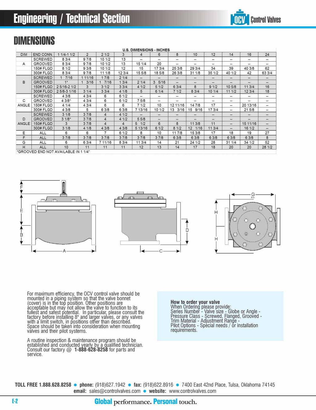
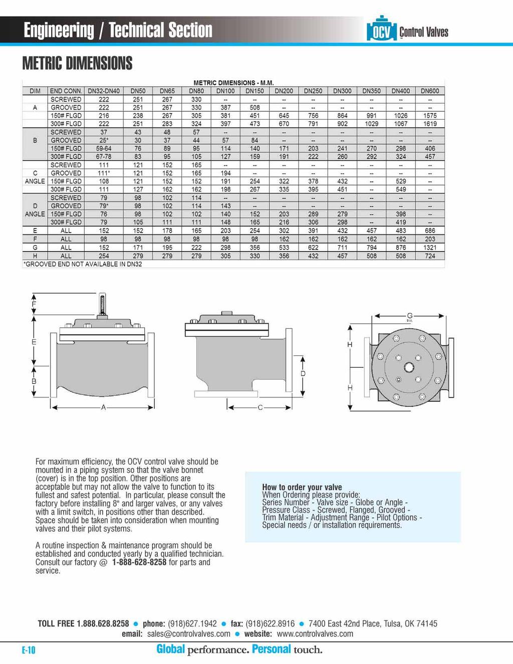
 SPECIFICATIONS DIMENSIONS In many liquid piping systems, it is vital that line pressure is maintained within relatively narrow limits. This is the function of the 108 Pressure Relief / Back Pressure Series
BACK PRESSURE / SUSTAINING
 In many liquid piping systems, it is vital that line pressure is maintained within relatively narrow limits. This is the function of the 108 Pressure Relief / Back Pressure Series of the OCV control valves.
FILTER BYPASS CONTROL
 Differential Control Valve Series 110 The Series 110 Differential Control Valve is designed to accurately control the pressure difference between any two points. In some systems this means the valve remains
SINGLE VALVE WITH LOW-FLOW BYPASS
 CONTROL VALVES Pressure Reducing Valve Sizing Guide Sizing pilot operated reducing valves is not a complicated process. It starts with determining requirements and following these guidelines in valve size
How to use the PBM Flow Calculator Spreadsheet (V2.04)
") How to use the PBM Flow Calculator Spreadsheet (V2.04) o Navigate to the F:\Common\ENGINEERING\Common Design Calculations folder o o Open PBM FLOW CALC 2.04.xlsm On the title page, the version, version
How to use the PBM Flow Calculator Spreadsheet (V2.04) o Navigate to the F:\Common\ENGINEERING\Common Design Calculations folder o o Open PBM FLOW CALC 2.04.xlsm On the title page, the version, version
Rate of Flow Valve Series 120
 SPECIFICATIONS Rate of Flow Valve Series DIMENSIONS The OCV Series 120 Rate of Flow control valve is designed to control or limit flow to a predetermined rate, regardless offl uctuations in downstream
Air Eliminators and Combination Air Eliminators Strainers
 Description Air Eliminators and Combination Air Eliminator Strainers are designed to provide separation, elimination and prevention of air in piping systems for a variety of installations and conditions.
Cavitation in Valves
 VM CAV/WP White Paper Cavitation in Valves Table of Contents Introduction............................... 2 Cavitation Analysis.......................... 2 Cavitation Data............................. 3
HYDRAULIC CONTROL VALVES
 HYDRAULIC CONTROL VALVES INC. VALVES, INC HYDRAULIC CONTROL VALVES WORKING PRINCIPALS It is automatic hydraulic control valve designed for make desired modulation processes in main valve network line as
Application Worksheet
 Application Worksheet All dimensions are nominal. Dimensions in [ ] are in millimeters. Service Conditions Medium Through Valve: Required C v : Temperature Maximum: Minimum: Normal: Flow Maximum: Minimum:
TUTORIAL. NPSHA for those who hate that stuffy word. by Jacques Chaurette p. eng. copyright 2006
 TUTORIAL NPSHA for those who hate that stuffy word by Jacques Chaurette p. eng. www.lightmypump.com copyright 2006 page.2 NPSHA for those who hate that stuffy word This article follows the same approach
TECHNICAL DATA. Pressure Regulation 531a. April 24, 2009
 April 24, 29 Pressure Regulation 531a 1. DESCRIPTION The Viking Regulating Valve is a direct-acting, single-seated, spring-loaded diaphragm valve. When installed as a pilot regulating valve on a Viking
Sapag Control valve MONOVAR
 MONOVAR MONOVAR is the energy dissipating valve Features MONOVAR DN 2000 (80 ) Extremely simple design (patented) Excellent cavitation characteristics Very accurate flow or pressure control Manual or automatic
TECHNICAL DATA Q= C. Table 1 - Specifications
 September 25, 2013 Pressure Regulation 537a 1. Description The Model B-3 Pilot Operated Pressure Control Valve is a factory assembled unit. The unit consists of a Model J-2 Halar coated Flow Control Valve,
The OCV Series 8000 float control valves are designed to maintain a SERIES FEATURES
 The OCV Series 8000 float control valves are designed to maintain a desired level in a tank or reservoir by opening for filling the tank when fluid is below the high level point and closing tightly when
Engineering Information. Flow Data. Flow Data. Importance of Valve Sizing. Estimating Cv or Orifice Size:
 Importance of Valve Sizing Improper sizing of a solenoid valve results in belowstan dard performance and can involve unnecessary cost. The basic factors in valve sizing include: Maximum and minimum flows
BERMAD Waterworks. Level Control Valve with Altitude Pilot. 700 Series. Model X. Features and Benefits. Major Additional Features
 Level Control Valve with Altitude Pilot High level reservoirs & water towers Energy cost critical systems Systems with poor water quality Inherent refreshing Level sustaining at reservoir outlet The Level
TECHNICAL DATA. Page 1 of 12
 Page 1 of 12 1. DESCRIPTION The Viking Regulating Valve is a direct-acting, single-seated, spring-loaded diaphragm valve. When installed as a pilot regulating valve on a Viking Model H or J Flow Control
TECHNICAL DATA PILOT PRESSURE REGULATED DELUGE SYSTEM CONTROLLED BY PNEUMATIC RELEASE. 1. DESCRIPTION (Refer to Figures 1, 2 or 3.
 Page 1 of 8 1. DESCRIPTION A Viking Pilot Pressure Regulated Deluge System utilizes a Viking Flow Control Valve to control water flow into the deluge system. The flow control valve must be installed with
1.2 Example 1: A simple hydraulic system
 Note: It is possible to use more than one fluid in the Hydraulic library. This is important because you can model combined cooling and lubrication systems of a library. The hydraulic library assumes a
TECHNICAL DATA CAUTION
 Page 1 of 12 1. DESCRIPTION The Viking Model C-2 Pilot Pressure Regulating Valve is a direct-acting, single-seated, spring-loaded diaphragm valve. When installed as a pilot regulating valve on a Viking
3-way control valves VK 3
 Data sheet 3-way control valves VK 3 Description / Application VK 3 valves are a range of 3 port high specification flanged valves for chilled water, LPHW, MPHW, HPHW (low, medium or high pressure hot
Pressure and/or Temperature Pilot Operated Steam Regulators Series 2000
 Hoffman Specialty Regulators Regulators Pressure and/or Temperature Operated Regulators Series 2000 The Hoffman Specialty Series 2000 consists of main valves, pilot valves, wells and hardware kits. They
TECHNICAL DATA PILOT PRESSURE REGULATED DELUGE SYSTEM CONTROLLED BY ELECTRIC RELEASE 1. DESCRIPTION 2. LISTINGS AND APPROVALS 3.
 Page 1 of 8 1. DESCRIPTION A Viking Pilot Pressure Regulated Deluge System utilizes a Viking flow control valve to control water flow into the deluge system. The flow control valve must be installed with
This portion of the piping tutorial covers control valve sizing, control valves, and the use of nodes.
 Piping Tutorial A piping network represents the flow of fluids through several pieces of equipment. If sufficient variables (flow rate and pressure) are specified on the piping network, CHEMCAD calculates
Application Notes for Valve Sizing Sizing valves for steam service with the aid of sizing charts
 Application Notes for Valve Sizing Sizing valves for steam service with the aid of sizing charts Application These application notes allow the variables (nominal valve size, steam flow rate) for self-operated
MWEA MAINTENANCE SEMINAR SPECIALTY VALVES POWER GLOBES
 MWEA MAINTENANCE SEMINAR SPECIALTY VALVES POWER GLOBES J O H N G. H U N T E R Types of Valves P A U L M A R C H I Accessories Principals of Operation Maintenance Control Valve Types Common Problems Key
Cash Valve TYPE KP PILOT OPERATED BACK PRESSURE VALVE. ISSUED - DECEMBER 2000 CAVMC-0518-US-0208 ISO 9001 Certified
 Cash Valve PILOT OPERATED BACK PRESSURE VALVE ISSUED - DECEMBER 2000 CAVMC-0518-US-0208 ISO 01 Certified KP HIGH CAPACITY PILOT OPERATED BACK PRESSURE VALVE DESCRIPTION The Cash Valve Type KP is a pilot
Waterous Relief Valve
 Operating Instructions 1. Reduce pump discharge pressure with engine throttle. Make sure four way (On/Off) valve is OFF. 2. Open at least one discharge valve. Accelerate engine until pressure gage indicates
ANDERSON GREENWOOD TANK BLANKETING REGULATORS
 Part of a complete system that incorporates a pilot operated, dome-loaded diaphragm type regulator capable of reducing blanketing gas in a single step, providing bubble-tight shut-off and low maintenance.
CONTROL VALVE TESTING
 The optimal functioning of the Control valve not only exists of sufficient body & seat tightness, but more important, the total "performance" of the valve and its controls! For an accurate and reliable
TECHNICAL DATA. Table 1 - Specifications
 Page 1 of 6 1. DESCRIPTION Model A-3 Pilot Operated Pressure Control Valves are factory assembled units. Each unit consists of a Model H-2 Halar coated Flow Control Valve, a Speed Control Valve, a Model
TECHNICAL DATA. the Viking Pilot Pressure Regulating Valve 1 Model A-1 Speed Control Assembly: OBSOLETE. the Viking Speed Control Assembly 1
 November 30, 1994 534 a 1. PRODUCT NAME VIKING 2" (50mm), 3" (75mm), 4" (100mm), 6" (150mm) 2. MANUFACTURER THE VIKING CORPORATION 210 N. Industrial Park Road Hastings, Michigan 49058 U.S.A. Telephone:
CASH VALVE TYPE KP BACK PRESSURE VALVES
 A high capacity pilot operated back pressure valve that offers accurate control and dependable protection against overpressure conditions FEATURES Automatically maintains maximum pressure in a vessel or
What is pressure relief valve? Pressure relief valve
 What is pressure relief valve? Pressure relief valve What is: Relief valve Safety valve Safety relief valve Type of pressure relief valve Pressure relief valve sizing base What are the sizing basis of
Pressure reducing valves Index
 Index General information page Introduction 506 General introduction 507 for a steam plant 509 Product information BSP thread page Brass 510 ; BSP female thread 511 ; BSP male thread 513 Stainless steel
SUBMITTAL NOTES PROJECT: Ross Model 50RWR-A Pilot Operated Surge Relief Valve with Hydraulic Anticipation. Size: inch / mm
 SUBMITTAL NOTES PROJECT: Ross Model 50RWR-A Pilot Operated Surge Relief Valve with Hydraulic Anticipation Size: inch / mm Every Ross Valve shall be hydrostatically tested for body integrity and tight seating
Versions. Benefits. Balancing DN15-32 DN40 DN50 DN15, DN20, DN25, DN32, DN40, DN50. Dimensions
 Ballorex Delta Description The Ballorex Delta is a differential pressure control valve used in hydronic heating or cooling systems. By ensuring a constant differential pressure across motorized or static
V311. Venta. Three-way Plug Valve, Flanged PN 16
 1 Three-way Plug Valve, Flanged PN 16 can be used in a wide range of applications, such as heating, cooling, air handling and domestic hot water systems. Soft EPDM seals provide tight shut off. The valve
Anti-Cavitation Trim. Eliminates cavitation damage Reduces noise Preserves valve and surrounding pipe systems. singervalve.com
 Anti-Cavitation Trim Eliminates cavitation damage Reduces noise Preserves valve and surrounding pipe systems Say Goodbye to Cavitation Damage! Cavitation, a common problem in pumps and control valves,
THE INNER WORKINGS OF A SIPHON Jacques Chaurette p. eng. January 2003
 THE INNER WORKINGS OF A SIPHON Jacques Chaurette p. eng. www.lightmypump.com January 2003 Synopsis The objective of this article is to explain how a siphon works. The difference between low pressure, atmospheric
NAF-Trimball Control Ball Valves
 NAF-Trimball Control Ball Valves Size DN 50-500, Size 2-20 PN 10 40, ANSI Class 150 and 300 Fk 41.65(9)GB 11.04 Primary characteristics The NAF-Trimball represents an entirely new approach for addressing
Methods of Rating Flow
 Methods of Rating Flow What engineers need to know when using CV as a measurement of flow in pneumatic applications In the pneumatic industry, CV is one standard for expressing the flow capacity of devices
Theory, Applications and Sizing of Air Valves
 Practice + Operations Theory, Applications and Sizing of Air Valves Val-Matic Valve & Mfg. Corp. When air is allowed to accumulate in pressurized pipelines, efficiency is sacrificed and serious damage
VACUVENT Valve functions - benefits - flowpath - VG series - Sewage
 01 VG Series air release and vacuum break valves Operation and benefits The topic of sizing and placement is significant and complex the purpose of this document is simply to point out important considerations
The 700 Series Roll Seal Control Valve is the Best Choice for All Your Special Applications
 The 700 Series Roll Seal Control Valve is the Best Choice for All Your Special Applications Pressure Reducing Valves Pressure Relief Valves Pressure Sustaining Valves Solenoid Operated Valves Rate of Flow
PRESSURE REGULATOR PRESSURE REDUCING. APPLICATION: Regulation of inlet pressure to gas compressors. Control of supply or distribution system pressure
 PRESSURE REGULATOR PRESSURE REDUCING APPLICATION: Regulation of inlet pressure to gas compressors. Control of supply or distribution system pressure PRESSURE RANGE: Ductile Iron: Upstream: psig to 125
TECHNICAL INSTRUCTIONS Iron Body Series 597 SI
 UTILITY IRON BODY CONTROL VALVES TI 597SI UTILITY IRON BODY SERIES DESCRIPTION The rugged Powers Type SI (single seat iron body) balanced valve is primarily used for steam and water modulating applications
Theory, Application, and Sizing of Air Valves
 VM AV/WP White Paper Theory, Application, and Sizing of Air Valves Table of Contents Introduction...................... 2 Three Basic Types of Air Valves....... 2 Air Release Valves................. 3
Practical Guide. By Steven T. Taylor, P.E., Member ASHRAE
 ractical Guide The following article was published in ASHRAE Journal, March 2003. Copyright 2003 American Society of Heating, Refrigerating and Air- Conditioning Engineers, Inc. It is presented for educational
PROCESS ROTATING EQUIPMENT (CENTRIFUGAL PUMPS )
") PROCESS ROTATING EQUIPMENT ( ) Slide No: ١ Pumps can be divided into two main groups: Displacement pumps Dynamic pumps Slide No: ٢ Slide No: ٣ Slide No: ٤ Slide No: ٥ BASIC CENTRIFUGAL PUMP PARTS Casing
PROCESS ROTATING EQUIPMENT ( ) Slide No: ١ Pumps can be divided into two main groups: Displacement pumps Dynamic pumps Slide No: ٢ Slide No: ٣ Slide No: ٤ Slide No: ٥ BASIC CENTRIFUGAL PUMP PARTS Casing
The Shand & Jurs Model Vapor Guard Tank Blanketing Valve
 Lower maintenance due to fewer parts Occupies less space, less stress to tank Teflon is inert to most chemicals; extends service life Simplifies and lowers maintenance cost Optimizes flow of blanketing
The Discussion of this exercise covers the following points: Pumps Basic operation of a liquid pump Types of liquid pumps The centrifugal pump.
 Exercise 2-3 Centrifugal Pumps EXERCISE OBJECTIVE In this exercise, you will become familiar with the operation of a centrifugal pump and read its performance chart. You will also observe the effect that
300 Series. Automatic Hydraulic Control Valves
 Automatic Hydraulic Control Valves AVFI Pty Ltd 54 Enterprise Drive Bundoora Vic 3083 p: 03 8467 0000 f: 03 8467 0099 e: avfi@avfi.com.au w: www.avfi.com.au 300 Series General 300 SERIES Automatic Hydraulic
Exercise 4-2. Centrifugal Pumps EXERCISE OBJECTIVE DISCUSSION OUTLINE DISCUSSION. Pumps
 Exercise 4-2 Centrifugal Pumps EXERCISE OBJECTIVE Familiarize yourself with the basics of liquid pumps, specifically with the basics of centrifugal pumps. DISCUSSION OUTLINE The Discussion of this exercise
VB-7323 Series. Application. Features. Applicable Literature. 1/2 to 2 Screwed NPT Three-Way Diverting Valves General Instructions
 VB-7323 Series 1/2 to 2 Screwed NPT Three-Way Diverting Valves General Instructions Application VB-7323 series three-way diverting valves control hot or chilled water in heating or air conditioning systems.
DANFLO Control Valves 400 Series Model 20
 DANFLO Control Valves 400 Series Model 20 Back Pressure/Pressure Relief The DANFLO Model 20 is a pilot operated valve suitable for use in gas or liquid facilities and requires no outside power for operation.
SINGER MODEL 106/206-RPS-L&H
 DESCRIPTION: Model 106/206-RPS-L&H dissipates surges caused by power failure to pumps. The valve anticipates the surge by opening on low line pressure associated with sudden stopping of pumps. This assures
BEFORE SALES AFTER SALES
 TALIS FP RANGE TALIS FP RANGE TALIS is a leading global provider of premium valves, hydrants and control solutions for water flow control and Fire Protection Systems With a varied range of products, Talis
DN300 DN2000 C Plunger Valve
 ל DN300 DN2000 C Plunger Valve P.O.B 46 MOSHAV SHTULA WESTERN GALILEE 2286500 Tl. +972-(0)77-6656101, Fax. +972-(0)77-6656196 Website: www.saisanketvalves.com www.saisanket.com email: saisanket@saisanket.com
Exercise 5-2. Bubblers EXERCISE OBJECTIVE DISCUSSION OUTLINE. Bubblers DISCUSSION. Learn to measure the level in a vessel using a bubbler.
 Exercise 5-2 Bubblers EXERCISE OBJECTIVE Learn to measure the level in a vessel using a bubbler. DISCUSSION OUTLINE The Discussion of this exercise covers the following points: Bubblers How to measure
Seated valves (PN 16) VF 2 2-way valve, flange VF 3 3-way valve, flange
 VF 2 2-way valve, flange VF 3 3-way valve, flange") Data sheet Seated valves (PN 16) VF 2 2-way valve, flange VF 3 3-way valve, flange Description VF 2 VF 3 VF 2 and VF 3 valves provide a quality, cost effective solution for most water and chilled applications.
Data sheet Seated valves (PN 16) VF 2 2-way valve, flange VF 3 3-way valve, flange Description VF 2 VF 3 VF 2 and VF 3 valves provide a quality, cost effective solution for most water and chilled applications.
P r o d u c t R a n g e Data sheet: P
 P r o d u c t R a n g e Data sheet: P245423-10 Pressure Reducing Maintains a constant downstream pressure regardless of upstream pressure or flow rate fluctuations. The set point of reduced pressure is
Models 106-RF / 206-RF Rate of Flow Control Valve
 Rate of Valve KEY FEATURES Accurately limits low to a pre-set maximum Easily adjustable low limit Paddle-style oriice plate included Optional oriice plate housing 106-RF Globe Product Overview The 106-RF
The Hoffman Specialty Series 2000 consists of main
 Pressure and/or Temperature Pilot Operated Steam Series 2000 The Hoffman Specialty Series 2000 consists of main valves, pilot valves, wells and hardware kits. They are designed to meet a wide range of
PLD 03 T A CASAPPA S.p.A.
 GEAR FLOW DIVIDERS INDEX Section Page GENERAL FEATURES... 3 GENERAL DATA... 5 FLOW EQUALIZER... 6 FLOW DIVIDERS... 8 TYPICAL CIRCUITS... 10 NOTES ABOUT COMPOSITION... 12 PORTS DIMENSIONS.... 14 GROUP DIMENSIONS...
PRESSURE REDUCING VALVE RP45 (EN)
") PRESSURE REDUCING VALVE RP45 (EN) DESCRIPTION The ADCA RP45 series pressure reducing valves are single seat bellows sealed controllers, operating without auxiliary energy, designed for use on steam, compressed
PRESSURE REDUCING VALVE RP45 (EN) DESCRIPTION The ADCA RP45 series pressure reducing valves are single seat bellows sealed controllers, operating without auxiliary energy, designed for use on steam, compressed
VB-7263 Series. Application. Features. Applicable Literature
 TAC 1354 Clifford Avenue P. O. Box 2940 Loves Park, IL 61132-2940 www.tac.com VB-7263 Series 1/2" to 2" Screwed NPT Stainless Steel Trim with Teflon Disc Stem Up Closed, Two-Way Valves General Instructions
FACHGESPRÄCH 3 NPSH NPSH3. Let us call it: CAVITATION A LOOK UNDER THE HOOD
 FACHGESPRÄCH 3 NPSH Let us call it: NPSH3 CAVITATION A LOOK UNDER THE HOOD OUR APPROACH TO LEARNING AT THIS PRESTIGIOUS W.T.F. FORMULAS DEFINITIONS B.U.T.Ts Broadly Useful Technical Tips T.I.T.S T.I.T.S
Seated valves (PN 6) VL 2 2-way valve, flange VL 3 3-way valve, flange
 VL 2 2-way valve, flange VL 3 3-way valve, flange") Data sheet Seated valves (PN 6) VL 2 2-way valve, flange VL 3 3-way valve, flange Description VL 2 VL 3 VL 2 and VL 3 valves provide a quality, cost effective solution for most water and chilled applications.
Data sheet Seated valves (PN 6) VL 2 2-way valve, flange VL 3 3-way valve, flange Description VL 2 VL 3 VL 2 and VL 3 valves provide a quality, cost effective solution for most water and chilled applications.
BAYARD is a company of. Hydraulic control valve Hydrobloc system
 BAYARD is a company of Hydraulic control valve Hydrobloc system Hydrobloc control valve 1 - Technical data Range: - DN 50 to 1000 for XGS design. - DN 50 to 800 for XG design. - DN 50 to 300 for XGA design
Bermad Pressure Reducing. Model: 42T
 Bermad Pressure Reducing Pilot Operated Pressure Control Valve Model: 42T Installation Operation Maintenance Manual (IOM) REV. 27.7.17 Page 1 of 12 Safety First BERMAD believes that the safety of personnel
VB-7273 Series. Application. Features. Applicable Literature
 VB-7273 Series 1/2" to 2" Screwed NPT Stainless Steel Trim Stem Up Open, Two-Way Valves General Instructions Application VB-7273 series single seat, stem down to close, two-way valves control water from
RELIEF CAPACITY CURVES
 E (800) 910-4295 www.hawk-eye.com TANKAGE VENTING RELIEF CAPACITY CURVES SERIES 6000 PVRV SERIES 4000 MARSH HAWK TRV SERIES 5000 EPRV RE SERIES 200 & 300 TVTH RE INTRODUCTION INTRODUCTION A relief capacity
Wastewater combination air valve in stainless steel AISI 316 Mod. SCS
 Wastewater combination air valve in Mod. SCS The air valve guarantees the proper operation of sewage/industrial lines allowing the entrance of large quantity of air in case of pipe bursting or draining,
VB-7212 Series. Application. Features. Applicable Literature. 5/8" O.D., 45 SAE Flared Stem Up Open, Two-Way Valves General Instructions
 VB-7212 Series 5/8" O.D., 45 SAE Flared Stem Up Open, Two-Way Valves General Instructions Application VB-7212 series single seat, stem up open, two-way valves control water from 20 to 281 F (-7 to 138
Modeling a Pressure Safety Valve
 Modeling a Pressure Safety Valve Pressure Safety Valves (PSV), Pressure Relief Valves (PRV), and other pressure relieving devices offer protection against overpressure in many types of hydraulic systems.
VB-7213 Series. Application. Features. Applicable Literature. 1/2" to 2" Screwed NPT Stem Up Open, Two-Way Valves General Instructions
 VB-7213 Series 1/2" to 2" Screwed NPT Stem Up Open, Two-Way Valves General Instructions Application VB-7213 series single seat, stem up open, two-way valves control water from 20 to 281 F (-7 to 138 C)
94270 Vapor Guard Tank Blanketing Valve Vapor Guard Tank Blanketing Valve What is Tank Blanketing? Features How does it work?
 94270 What is Tank Blanketing? blanketing systems are used to prevent the escape of liquid vapors into the atmosphere or to prevent moisture from entering a tank and contaminating its contents. A tank
VBS-9263 Series. Application. Features. Applicable Literature
 TAC 1354 Clifford Avenue P. O. Box 2940 Loves Park, IL 61132-2940 www.tac.com VBS-9263 Series 1/2" and 3/4" Screwed NPT 316 Stainless Steel Stem Up Closed, Two-Way Valves General Instructions Application
Liquid Level Controllers
 Liquid Level Controllers ALL PUMPS LLC-2Y For both pump up and down control. Variable On/Off set points. NDP-15/20/25/32, DP-10/15 & *NDP-40/50/80 LLC-1 Pump up and down versions available. 6 to 12 differential
Cover Page for Lab Report Group Portion. Pump Performance
 Cover Page for Lab Report Group Portion Pump Performance Prepared by Professor J. M. Cimbala, Penn State University Latest revision: 02 March 2012 Name 1: Name 2: Name 3: [Name 4: ] Date: Section number:
TD45 Thermodynamic Steam Trap Installation and Maintenance Instructions
 0685255/1 IM-P068-47 ST Issue 1 TD45 Thermodynamic Steam Trap Installation and Maintenance Instructions 1 General safety information 2 General product information 3 Installation 4 Commissioning 5 Operation
AIR AND VACUUM VALVES
 MINING DIVISION AIR AND VACUUM VALVES FOR HIGH FLOW K-6NS SERIES DESCRIPTION The K-6NS Series Air and Vacuum Valve discharges air during the filling or charging of the system and admits air into the system
Ø248 Ø Series. R 2.00 R 2 Hydraulic Control Valves R 3 R 6 SEE "SEAT DE T DETAIL NO. 2" CONTROL VALVES
 Ø290 Ø248 Ø240 RAM Ø201 400 Series R 2.00 R 2 Hydraulic Control Valves R 3 G 50 92 30 R 6 SEE "SEAT DE T DETAIL NO. 2" Ø290 Ø248 Ø240 Ø201 30 i n d e x How To Order R 2.00 R 2 2 Company profile 4 Hydraulic
DAV - P. Product Catalogue DAV - P. Air release & Vacuum Break Valves. (Plastic Air Valves) DAV - P. Edition 2012
 DAV - P. Edition 2012") Product Catalogue DAV - P DAV - P Air release & Vacuum Break Valves Edition 1 DAV - P (Plastic Air Valves) DAV Series Overview General The presence of trapped air in a pressurized pipeline can have serious
Product Catalogue DAV - P DAV - P Air release & Vacuum Break Valves Edition 1 DAV - P (Plastic Air Valves) DAV Series Overview General The presence of trapped air in a pressurized pipeline can have serious
DFT Valves. Selecting Control Valves
 DFT Valves Selecting Control Valves Evaluating Process Conditions in Control Valve Selection A one-size-fits-all approach is not the best way to go about choosing the proper control valve for a particular
Installation and operation Manual. Bermad Surge Anticipation Valve. Model No 435
 Instruction manual Bermad surge anticipation manual Model No 435 Installation and operation Manual Bermad Surge Anticipation Valve Model No 435 Bermad Water Technologies Rev 0 5/05/2015 7 Inglewood Drive,
VB-7211 Series. Application. Features. Applicable Literature. 1/2" to 1-1/4" Union End NPT Stem Up Open, Two-Way Valves General Instructions
 TAC 1354 Clifford Avenue P. O. Box 2940 Loves Park, IL 61132-2940 www.tac.com VB-7211 Series 1/2" to 1-1/4" Union End NPT Stem Up Open, Two-Way Valves General Instructions Application VB-7211 series stem
700 SIGMA SERIES ENGINEERING DATA
 700 SIGMA SERIES ENGINEERING DATA CONTENT 700 SIGMA EN/ES 2-8 700 SIGMA EN/ES 2 Exploded View 3 Material Specifications 4 Principle of Operation 5 Plug Options 6 Cavitation 7 Cavitation Cage 8 700 SIGMA
BERMAD Waterworks. Pressure Reducing Valve. 700 Series. Model 720. Features and Benefits. Major Additional Features
 Pressure Reducing Valve Flow and leakage reduction Cavitation damage protection Throttling noise reduction Burst protection System maintenance savings The Pressure Reducing Valve is a hydraulically operated,
The Discussion of this exercise covers the following points:
 Exercise 5-3 Wet Reference Leg EXERCISE OBJECTIVE Learn to measure the level in a vessel using a wet reference leg. DISCUSSION OUTLINE The Discussion of this exercise covers the following points: Measuring
Self-operated Pressure Regulators Type 2405 Pressure Reducing Valve
 Self-operated Pressure Regulators Type 2405 Pressure Reducing Valve ANSI version Application Pressure reducing valve for set points from 0.075 to 150 psi (5 mbar to 10 bar) Valve size NPS ½ to 2 1) (DN
Pressure Regulators Pressure regulation to maximize steam system efficiency
 Pressure Regulators Pressure regulation to maximize steam system efficiency The density of steam increases as the pressure rises. Because of this characteristic, more pounds of steam can be stored in a
SB AXIAL FLOW VALVES
 SB9509.3 AXIAL FLOW VALVES The improved technology for pressure regulation The American Axial Flow Valve provides pressure and flow control in high capacity pipelines. It can be used for pressure regulation,
LESER Deutschland Standard Functional Tightness Test (Cryo) Content
 Content") Page 1/10 Content 1 Purpose... 1 2 Scope... 1 3 Range of Application... 1 4 Normative Background... 2 5 Terms and Definitions... 2 6 Test Equipment... 3 7 Test Procedure... 5 8 Acceptance Criteria... 8
Page 1/10 Content 1 Purpose... 1 2 Scope... 1 3 Range of Application... 1 4 Normative Background... 2 5 Terms and Definitions... 2 6 Test Equipment... 3 7 Test Procedure... 5 8 Acceptance Criteria... 8
Understanding Net Positive Suction Head
 Understanding Net Positive Suction Head Atmospheric Pressure Until the early 17 th century air was largely misunderstood. Evangelista Torricelli, an Italian scientist, was one of the first to discover
TECHNICAL DATA DELUGE VALVE, MODEL F-1 STRAIGHT THROUGH STYLE
 Page 1 of 10 1. DESCRIPTION The Viking Model F-1 Deluge Valve is a quick opening, differential diaphragm and flood valve with one moving mechanism. The Deluge Valve is used to control water flow in Deluge
T 2523 EN Type 2406 Excess Pressure Valve Self-operated Pressure Regulators ANSI version
 T 2523 EN Type 2406 Excess Pressure Valve Self-operated Pressure Regulators ANSI version Application Excess pressure valve for set points from 0.075 to 150 psi (5 mbar to 10 bar) Valve size NPS ½ to 2
Simple Set Max. Pressure Independent Control Valves 2 Way 2-1/ /09/18
 The Bray Simple Set Max is a flanged pressure independent control (PIC) valve designed for a wide variety of hot water and chilled water control applications. The SSM Series combines high rangeability