OPTIMUM SELECTION OF WELL CONTROL METHODS
|
|
|
- Daniella Hood
- 6 years ago
- Views:
Transcription
1 OPTIMUM SELECTION OF WELL CONTROL METHODS Md AHAMMAD SHARIF Assistant professor, Department of Petroleum Engineering, GIET College of Engineering, Rajahmundry. Dr. S. SRIGOWRI REDDY Professor, GIET College of Engineering, Rajahmundry. KORIBILLI UMA SANKAR IV B.Tech student of Petroleum Engineering Department, GIET College of Engineering, Rajahmundry. ABSTRACT Well control and blowout prevention have been particularly important topics in the hydrocarbon production industry for many reasons. Among these reasons have been higher drilling costs, waste of natural resources, and the possible loss of human being life when kicks and blowouts occur. One concern is the increasing number of governmental regulations and restrictions placed on the hydrocarbon industry, it is important that drilling personnel understand well-control principles and the procedures to follow properly and to control potential blowouts with help of well-control equipment The key elements that can be used to control kicks and prevent blowouts are based on the work of a blowout specialist and are briefly presented as quickly shut in the well, when in doubt- shut down properly in manual and get help. Kicks occur as frequently while drilling as they do while tripping out of the hole. Many small kicks turn into big blowouts because of improper handling, Act cautiously to avoid mistakes and take your time to get it right the first time. You may not have another opportunity to do it correctly. Various well control methods have been discuss and on optimum method among those as been chosen in this following presentation INTRODUCTION The main focus during a drilling operation is to keep the wellbore pressures stable and prevent any type of influx of formation fluids. Inflow of formation fluid is called a well control. In every well different phase like drilling, completion, production etc well barriers are the most important system to prevent unwanted situations. Their intention is to avoid a catastrophe and to have the ability to regain well control if the situation should arise and escalate. All operations must be planned and conducted in a way that no uncontrolled inflow of formation fluid enters the wellbore, e.g. in the drilling phase one want to avoid kicks. Because of the high damage a blowout can cause economically and catastrophically, a lot more research is going on the well control procedures to make sure a safely drilling process. The blowout in an average producing well can cause damages ranges from 1 million to 10,000 million USD. 6
2 PRESSURE IN RESERVOIRS: The pressure control is a basic concept of a perfect drilling process, if engineers lose control of the formation pressure the result is a potential blowout. This table provides a brief description of different pressures in reservoir which are the responsible for formation of kick and well control issues. S.No PRESSURE TYPE DESCRIPTION 1 Hydrostatic Pressure Hydrostatic Pressure is the force per unit area exerted by a body of fluid at rest. 2 Overburden Pressure Over burden pressure is the combined damage of the formation material and fluid at a particular depth of interest. The over burden pressure is directly related to the compressibility of the formation. 3 Pore Pressure Pore pressure is the pressure of fluid within the pore spaces of the formation rock. It depends upon the weight in depth of overlying formation rock which exerts the pressure on both the rock material and the fluids present in the pores of rock. 4 Fracture pressure Fracture pressure is the amount of pressure required to permanently collapse the formation. 5 Hydraulic pressure The hydraulic pressure is the pressure required to circulate the drilling fluid into the drilling operation. This is the pressure generated by the mud pump to move the drilling fluid from the mud pump passing thorough the drill pipe and back to the surface through the annulus. 6 Bottom-hole Pressure The bottom-hole pressure is the sum of all the pressures exerted at the bottom of the wellbore REASONS FOR KICK: - There are several factors that affect extent of a kick, these are the differential pressure between the wellbore and formation. Also the formation properties like porosity and permeability are important. In order to generate a kick the pushing force from the formation and into the wellbore must be higher than the force holding formation fluid back or containing it in its original placed. When the hydrostatic pressure in wellbore, that force is not able to hold back the formation pressure it will lead to inflow of formation fluids is called kick. There are several reasons that can lead to a kick, these are retrieved from:- Insufficient mud weight Improper hole fill-up on trips Swabbing Gas cut mud Lost circulation 7

3 INSUFFICIENT MUD WEIGHT: Kick will occur if the pressure from the formation is higher than the hydrostatic pressure from the mud column in the well. Therefore it is important to have a mud weight that will exceed the formation pressure but still be within the drilling window lower than the fracture pressure and higher than the pore pressure. Insufficient mud weight is often related to unexpected pore pressures in a zone which may lead to a well control situation IMPROPER HOLE FILL-UP ON TRIPS: Improper hole fill-ups is another cause of kick. It is important to pay attention when tripping out because this may lead to a kick situation. Tripping is when drill pipe is pulled out of or in to a well. When tripping out drill pipe steel volume will be replaced with mud, this will reduce the height of the annular mud column with the result of a lower bottom hole pressure. It is therefore very important to pay careful attention when tripping to avoid a kick. SWABBING: Swabbing is another effect that may cause a kick. When pulling the pipe there will be a piston type force between the drill pipe and the wellbore walls, this creates a pressure reduction beneath the drill pipe/bit which reduces the effective hydrostatic bottom hole pressure. If the effective hydrostatic pressure is reduced below formation pressure a kick situation may be the outcome. It is therefore important that certain parameters are carefully monitored, such as tripping speed, hole configurations, mud properties, and the effect of "balled" equipment. Balled equipment is when clay, sandstone etc. sticks to the pipe or bit and makes a larger outer diameter of the equipment. This increases the swab effect GAS CUT MUD Kick caused by gas cut mud are not common. When drilling formations containing hydrocarbons, small amounts of gas from the drilled out formation will be present in the well. The gas within the cuttings will on its way up to the surface be released and it expands and reduces the hydrostatic pressure and this can lead to a kick. 8
4 LOST CIRCULATION Lost circulation may also lead to a kick scenario. One outcome is loss of drilling fluid when entering a zone with high permeability, this happens because the formation is unable to prevent drilling fluid from entering the permeable zone. E.g. a mitigation action in such a case can be to add lost circulation pills (LCM) in the mud that will build a filter cake on the bore walls and prevent further losses. Another aspect is if the weight of drilling mud is too high compared to the formation strength. The increased hydrostatic pressure may exceed the fracture pressure creating cracks where mud can be lost. For both cases above, mud level in the annulus will fall with the result that bottom hole pressure is reduced. Should the hydrostatic pressure in the wellbore go beneath the formation pressure, influx of formation fluids will be a result and a kick is in progress. CAUSES OF MUD LOSSES Formation is naturally fractured Subnormal formation pressures which is pressures less than the normal formation pressure Surge pressures when running the drill string or casing can lead to formation fractures (induced fractures) Drilling pack off in the annulus, e.g. caused by poor cuttings transport The gel strength of mud is too high, i.e. large pressure peaks are induced when resuming circulation (has to break circulation by first starting rotation) Casing cement around casing shoe has poor quality Extensive pressure losses in the annulus leading to too high ECD DETECTION OF A KICK Drilling operations are not without risk, and the one with high focus is kick detection. These are some key warning signs/indicators/detection of kick Flow rate increase Pit volume increase Flowing well with pumps off Decreasing pump pressure and increasing pump strokes Improper hole fill-up on trips String weight change Drilling break e.g. when drilling into an open hole which increase the ROP significantly During a drilling operation each crew member is responsible for carefully monitoring the different kick indicators which are listed above. It is their responsibility to take actions if any indicator shows that an unwanted situation is under development. There are on the other hand not all indications of a kick that 9
5 actually lead to a kick, e.g. an increase in pit volume when taking connections may be because of temperature effects, and should be monitored by "fingerprinting" each connection this means identifying the volume increase in the pit tank for every connections to monitor the trend. If there are any anomalies in the "prints" this may indicate a real kick. If a kick is taken in OBM it can be difficult to detect on surface, the gas will be dissolved in the oil and no expansion will be observed in the pit tank. During the time it takes before some changes are observed at surface, there is a risk that large volumes of formation fluid have entered the wellbore. And when this reaches the flash point it will boil out of suspension creating a large kick. The flash point needs to be below the BOP where it can be contained. KICK DETECTION AND MONITORING WITH MWD WITH TOOLS Measurement while drilling (MWD) system is monitoring mud properties, formation parameters and drill-string parameters during circulation and drilling operations The system is widely used for drilling, but it also has applications for well control. The MWD tool offers kick-detection benefits if the response time is less the time it takes to observe the surface indicators. The tool can provide easy to detection of kicks and potential influxes as well as monitor the kick-killing process. This tool response time is a function of the complexity of the MWD tool operation. The sequence of data transmission determines the up-to-date times of each type of measurement. Many MWD tools allow for reprogramming at up-to-date sequence while the tools in the hole. These features are enable the operator to increase the update frequency of critical information to meet the expected needs of the section being drilled. If the tool response time is longer than required for surface indicators to be observed, the MWD only serves being drilled. If tool is response time more than required time for surface indicators to be observed, the MWD only serves as a confirmation source. BARRIERS Barriers can be defined as the components or practices that contribute of the total system reliability to prevent or stop formation fluids or gases flow in to wellbore. PRIMARY AND SECONDARY BARRIERS TO THE FLOW OF HYDROCARBONS IN THE FORMATION The main goal during drilling process is to conform that hydrocarbons do not allow into the wellbore from the formation. To achieve this goal engineers use different barriers to stop entering the flow. 10

6 WELL-CONTROL EQUIPMENTS No Name of the equipment Brief Description 1 Casings 2 Wellhead 3 Annular Preventers 4 Ram Type Preventers 5 Drilling Spools 6 Operating equipment 7 Choke Casings are used to prevent the borehole pressures from the falling in during drilling; it is also provide the controlling fluids encountered during drilling. The wellhead settled between the BOP stack and the next strings of casings. The wellhead rests on a base plate supported by the conductor pipe that is used to activate the well. Annular preventers are the part of the BOP system and they seal the annular space during the kick situations to stop further flow of formation fluids from the annulus. Ram Preventers are also a part of the BOP system and they seal the wellbore during the kick situations by cutting through the drill pipe. A drilling spool is designed to connect BOP and wellhead. A drilling spool has side outlets for kill and chokes lines fitted between the BOP stack and wellhead. The operating and control equipment, are basically the control panels to control the blowout prevention assembly. Choke is a equipment used to control the flow rate, it is one of the most important part in well control equipment. The oil production rate can be altered by adjusting the choke size. Chokes can be used in surface or subsurface. 11
7 8 Mud Pit Level Indicator 9 Degasser It informs about the mud level in the mud storage tank, if the well is flowing its level will start increasing and will alert the crew members to take necessary steps to stop the kick. A degasser is used to extract entrained gas in the drilling fluid, it is installed in the mud control facility and the returning mud is passed through the degasser. SHUT-IN PROCEDURES FOR WELL CONTROL When one or more warning detect of kicks are observed, steps should be taken to shut in the well. If there is any doubt that the well is flowing, it should shut in and check the pressures. It is important to remember that, there is no difference between a small-flow and full-flowing into the well, because both can very quickly turn into a big blowout. There is some concern about the fracturing of well and creating an underground blowout resulting from shutting in the well, when a kick occurs. If the well is allowed to inside the flow, it will eventually become necessary to shut-in the well, in which time the possibilities of fracturing the well will be greater, if the well had been shut in immediately after the initial kick detection. Table shows an example of higher casing pressures resulting from continuous flow because of failure to close in the well. THIS IS THE EFFECT OF CONTINUOUS INFLUX ON THE CASING PRESSURE RESULTING FROM FAILURE TO CLOSE IN THE WELL Volume of gas gained (bbl) Casing pressure (psi) WELL-CONTROL PROCEDURES Well-control defined as the methods that are used to minimize the potential for the well to flow or kick and to maintain the well control in the event of kick. Wellcontrol applies to different stages in drilling, well-completion, well-workover, abandonment, and well-servicing operations. It includes measures, practices, procedures and equipment, such as fluid flow monitoring, to ensure safe and environmentally these operations as well as the installation, repair, maintenance, and operation of surface and subsea well-control equipment. The constant-bottomhole-pressure concept, that the total pressures (e.g., mud hydrostatic pressure and casing pressure) at the hole bottom pressures are maintained at a value slightly greater than the formation pressures to prevent further flow of formation fluids into the wellbore. And, because the pressure only slightly greater 12
8 than the formation pressure, the possibility of inducing a fracture and an underground blowout is minimized. This concept can be implemented in four ways: 1. Driller`s Method 2. Wait and Weight 3. Bull-heading 4. Volumetric Method The placing of the drill string determines which method is the best for killing the well. In order to use methods (1 and 2) the drill string must be on bottom, the two other methods (3 and 4) becomes an alternative if the drill string is way off bottom with no possibility to get down to TD or drill pipe circulation has been obstructed. Bull-heading, however, is also an alternative if the drill string is on bottom. Having a near to constant bottom hole pressure when killing the well is a common practice for both Driller`s method and W&W method, for Volumetric method and Bull-heading the bottom hole pressure can vary more during the well kill operation. This means that the pump pressure from the surface, plus the hydrostatic mud pressure is equal to or preferably higher than the formation pressure without exceeding the fracture pressure during the well kill operation. By maintaining constant bottom hole pressure and assuming that the well is able to take the circulation, no more formation fluid are able to enter the wellbore and escalate the situation. Bottom-hole pressure is controlled by regulating the choke pressure at surface, it enables bottom hole pressure control between the pore pressure and fracture pressures. Then, re-establishing well control should go safe and according to plan. Pump pressure when circulation starts is the ICP (Initial Circulation Pressure), and when kill mud enters the annulus it is the FCP (Final Circulation Pressure) that is used in the kill sheet. The kill sheet is the pump pressure the driller has to maintain during the well kill. In this way the bottomhole pressure is maintained constant. Bottom-hole pressure is related to ICP and FCP 13
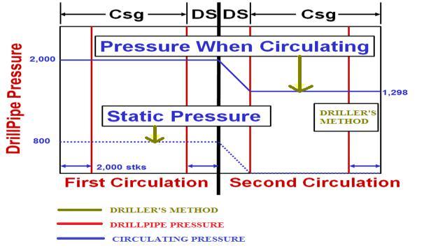
9 DRILLER S METHOD / TWO-CIRCULATION METHOD The Driller`s method is one of the oldest well killing methods and it was developed for shallow vertical wells. As time moved on, wells got deeper and went from vertical into more inclined pathways. The method got further developed to overcome the new challenges related to deviated well paths. Driller's method, also known as the two-circulation method, means that the kick is circulated out in two stages. In this method the drill string needs to be placed at the bottom in order to be fully utilized. In the first stage the objective is to remove the kick from the annulus and re-establish the primary well barrier. This is done by shutting in the well and trapping the kick to minimize inflow, then a couple of calculation steps are performed and the circulation process can begin. The process can also uses a remote controlled choke, its purpose is to control the choke line back pressure to maintain a constant bottom hole pressure during the circulation process. It should also work together with the mud pump(s) in a synchronized manner to maintain the bottom hole pressure constant and preferably above the inflow pressure, but keeping it beneath the formation fracture pressure at the same time during the entire kick circulation process. Old mud is used in the first circulation stage to remove the kick from the wellbore, and there will be no decrease in the drill pipe pressure during this operation. The second stage is to weight up new kill mud and repeat the circulation procedure until the new kill mud have completely filled the wellbore. Now the well is in balance and well control is regained. VERTICAL WELL WITH BOP ON PLATFORM DECK Figure - Showing the well schematics when drilling a well Before the Driller`s method can be initiated there are some main steps that shall be followed when suspecting a kick. These are: Kick detection Stop mud pumps and rotation of the drill string rotation Close the BOP 14
10 Monitor the shut-in pressure until it levels out the wellbore pressure is equal to formation pressure Then open choke line and circulate the kick out through the choke line to the separator/flare Driller method: circulate out the kick before introducing kill mud Wait and weight: start pumping kill mud while circulating out the kick Another option is to reverse kill or bull-head, this is done by forcing the kick back into the formation. Kill sheet using driller`s method of well control How the drill pipe pressure behaves during the kill circulation throughout the two stages. The constant bottom hole pressure in the annulus during circulation is achieved by tuning the choke pressure such that the pump pressure follows the kill sheet, The first stage in the figure is when original mud is used to circulate out the kick, the ICP (Initial Circulating Pressure) is calculated to know which pump pressure one need in order to maintain a bottom hole pressure slightly higher than the formation pressure. When the kick has been circulated out kill mud is introduced, this can be observed when the line goes from a straight line and dips down to a slope. After the new kill mud has displaced the entire drill string and enters the annulus it goes back into another straight section, this section is the FCP (Final Circulating Pressure) stage. 15
11 Shows a typical pressure development for Driller`s method Shows in above choke pressure development during a kill operation. It illustrates the choke pressure development during a kick circulation for Driller`s method. It can be used to enhance understanding of how the operation is performed. We see that the choke pressure will increase until the front of the kick has reached the surface. This represents the situation where we have the largest gas volumes in the well (lowest hydrostatic gradient). Hence, a very high choke pressure is required to maintain a constant bottom hole pressure. The choke regulates the well pressure during circulation. Here the kill line can be used to pump fluids into the well or it can be used as a secondary choke line, e.g. MEG which is used to avoid hydrates in the choke line during circulation. The main function of the choke line is to circulate out the kick safely and according to procedures. ADVANTAGES AND DISADVANTAGES WITH THE USE OF DRILLER`S METHOD Advantages of the Driller`s method Disadvantages using Driller`s method Not many calculations Surface equipment is exposed to the highest pressures. The front of gas kick holds the largest pressure due to the reduction of the hydrostatic pressure from the mud column It is possible to start the kill circulation at ones if required and possible. However, if the kick is taken in a situation where high mud weight is being used, there is a possibility that the gas intrusion can lead to precipitation of weighting material that falls out of suspension. An example can be barite which can result in a stuck drill string The well is usually under maximum pressure for a long period since Driller`s method takes long time Due to long choke exposure time during the two stages, there are some danger of washout 16
12 WAIT & WEIGHT METHOD / ONE-CIRCULATION METHOD Wait and Weight (W&W) is also known as the Engineering Method. This method was developed some time after the Driller`s method was put into use. It started out from this reasoning: Why use two circulations like the Driller`s method? Why not circulate new kill mud simultaneously as the kick is pumped out? The W&W method is also known as the one circulation method. During this procedure it is still important to have bottom hole pressure (BHP) control, make sure that it is stable and constant during the entire kill operation. The main difference between W&W compared to the Driller`s method is that kill mud is introduced at once in the circulation process with the intention to re-establish the well barrier. In Driller`s method there are always a constant fluid column either in drill string or in annulus, for W&W this is not the case. Here the annulus mud is mixed with inflow fluid with the result of varying hydrostatic column, also for the drill string the hydrostatic column will change. In the drill pipe, when kill mud replaces old mud in the drill pipe it will changes the hydrostatic column, this will affect the pump pressure and it is therefore more important to follow the kill sheet in this method. In the beginning, when mud is replaced simultaneously as kick circulation starts up, there will be no constant mud column in the drill string. Mud column will change as new mud travels down the drill string. Also, inflow fluid in the annulus will change the composition of the mud as it moves upwards in the annulus. This will have an impact on the hydrostatic pressure in the annulus form the mix mud column on the bottom hole pressure, and if needs to be compensated with the choke pressure to avoid it from going below the pore pressure. This is the reason why it is so important that the kill sheet is correctly followed, then mistakes are eliminated and the risk of having a bottom hole pressure either over or underneath the pressure window in the pore and fracture plot are eliminated. 17
13 Static drill pipe pressure using Wait and Weight method of well control In the W&W method we have to wait after the kick is taken. In a shut in well the pressures on top annulus and drill pipe will go up until the BHP and formation pressure has stabilized and inflow has stopped. At this point the SIDPP and SICP are measured, and based on the values the necessary calculations can be performed to find the new mud weight. The operation has the intention to re-establish the primary well barrier and the new kill mud should be able to balance the well conditions on its own. If the W&W method is done correctly the used time will be 2/3 compared to using the Driller`s method. The choke pressure development during a W&W operation is illustrated below, here it can be seen that the max choke pressure is when the front of gas bubble reaches the choke. Shows choke pressure development in a W&W operation The figure illustrates a typical choke pressure for a W&W operation and it is retrieved form to sum up the W&W method, it has its positive and negative sides. ADVANTAGES AND DISADVANTAGES WITH THE USE OF WAIT AND WEIGHT METHOD 18
14 Advantages If all goes according to plan, this operations can be done in one circulation It will be exposed to larger pressures over a shorter period compared to Driller`s method Disadvantages Before starting up, the well needs a lot of circulations Prior to circulation the well may be held shut-in for a long time, this is because the mud needs to be weighted up to the kill mud weight at the surface Harder to keep a constant bottom hole pressure, therefore it is important to monitor the pumping schedule to keep the pressure above formation pressure or equal If the calculated mud weight is too low they may not be able to increase it during the one circulation, but needs to perform a second circulation run BULLHEADING Operators sometimes have to look at different alternatives to solve critical well control problems. When conventional method of circulating down the drill string and up the annulus no longer is an option, an alternative is to use a technique called bull-heading. This method is performed with the use of pumps in a closed in well, the influx fluids are then pushed- and forced back down into the weakest point of the exposed open-hole interval. In this way well control is regained. Bull-heading method may also be the safest option if personnel do not hold the right knowledge to calculate the pressures and volumes required to perform a conventional kill circulation process. It is also the only option if the H 2S content is too high to be handled on surface, another if the kick is too large with respect to separator capacities or there is a potential risk of breaking the casing shoe. When a bull-heading operation is performed it is important that the pump pressure is noted throughout the process, here the LOT/FIT diagram can be used. In this way it is easier to control the situation, and if the process starts to develop in an unwanted way actions can be initiated immediately. Bull-heading is done by adding some pressure, in this way the wellbore pressure gets overbalanced compared to the reservoir pressure and the formation fluids are pushed back into the formation. The pressure acting on the bottom during a bull-heading operation is. P BH = P res + P over Where: P BH = Bottom hole pressure P res = Reservoir pressure P over= Overpressure 19
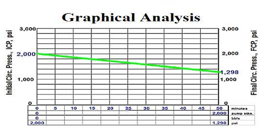
15 Advantages The H2S readings is above the operator limit Due to obstacles in the drill pipe it is not possible to get kill mud down to the bottom The kick will lead to too high surface pressures When weak zones below the kick prevent the use of conventional methods due to potential large mud losses To save time if the available resources are not adequate to handle the situation Disadvantages No obvious sign for the operators/crew when to use this technique or not The fluid flow will follow in the direction of least resistance, and it is not given that it will follow a desired pathway A potential risk of creating blowout either at surface or underground VOLUMETRIC The Volumetric method is based on the assumption that the influx is gas that migrates upwards in the well. It cannot be used if the influx fluid is either salt water or oil. Compared to Driller`s method and W&W method the Volumetric method is used in situations where there are no possibility to circulate out the kick conventionally. The reasons for using this method instead of another kill method are based on different variables in the well. Some of them are listed below: If the drill string is on its way in the well or out of it, if this is the case an attempt to run it to the bottom with the drill string should be made If there are no drill string in the well If the drill bit or the drill string has been plugged with some kind of debris or lost circulation material (LCM), to open the plugged area explosives can be an alternative Hole collapse can be a reason this prevents circulation It there has been a power failure and mud pumps along with emergency pumps are down If there is a long way between drill string and bottom of the well Not able to circulate due to drill string has been cut and dropped into the well 20
16 In this method the choke is opened and closed in steps to bleed of the inflow gas. It is performed by staying within the designated pore and fracture pressures together with a safety margin. As gas moves up and pressure in the well increases, the choke is opened to bleed off and reduce the well pressure and it is then closed when the pressure drops to a certain level. This procedure is maintained until the gas is completely out of the well. In the Volumetric method the gas is allowed to expand as it moves upwards in the well while the bottom hole pressure is held more or less constant. In theory, the Volumetric method states that a hydrostatic pressure can be represented with a given volume of mud by expressing the pressure in bars/litre, this is done by dividing the pressure gradient of mud (bars/meter) with annulus capacity (litre/meter) instantaneously over the top of the kick. Example:- When circulating at a killing rate of 40 strokes per min, The circulating pressure = 1200 psi The capacity of the drill string = 2000 strokes Mud weight = 13.5 lb/gal Well depth = ft Aggie Drilling Research division of PETE Dept., TAMU college Station, TX Pressure Control Worksheet 1. PRE-RECORDED INFORMATION System Pressure 40 stks = 1200 psi Strokes Surface to bit = 2000 stks Time surface to bit 2000 stks/40 stks/min = 50 min 2. MEASURE Shut-in drill pipe pressure (SIDPP) = 800 Psi Shut-in casing pressure (SICP) = 1100 Psi Pit volume increase (kick size) = 40 bbl 3. CALCULATE INITIAL CIRCULATING PRESSURE (ICP) ICP=System pressure loss + SIDPP= = 2000 Psi 4. CALCULATE KILL MUD DENSITY (NEW MW) Mud Weight increase = SIDPP / (0.052 * Depth) = 800/(0.052 * 14000) = 1.10 lb/gal Kill Mud density (New MW) = Old MW + MW increase = = 14.6 lb/gal 5. CALCULATE FINAL CIRCULATING PRESSURE (FCP) FCP = System Pressure Loss* (New MW/Old MW) = 1200 * (14.6/13.5) =1298 Psi 21

17 22
18 COMPARISON BETWEEN DRILLER S METHOD AND WAIT & WEIGHT METHOD Driller s and waits and weight methods are generally used to circulate wellbore influx while maintaining bottom-hole pressure constant. There are a lot of opinions regarding which method is best for well control operation. WELLBORE PROBLEMS WHILE KILLING THE WELL Where ever in oil operations, wellbore instability is one of major wellbore issues. If the drill string is kept in a static condition for a period of time, the pipe may be get stuck easily. In this situation, Driller s method will give you a better chance to successfully kill the well and minimizing wellbore collapses and pack off -than Wait and Weight method. For Wait &Weight method is kill mud weight must be prepared prior to circulation therefore the drill strings are in static condition with no circulation for a while. There are more chances for wellbore to collapse and pack the drill-string. Casing Shoe Pressure The shoe will be exerted by the maximum pressure when top of gas kick is at the casing shoe. Once the gas pass the shoe, the shoe pressure will remain constant. The Wait &Weight method can be reduce shoe pressure when the kill weight mud goes into the annulus space before the top of gas arrives at shoe. If the operation has larger drill-string volume than annular volume that will not be able to lower the shoe pressure using Wait and Weight method. However, if time to prepare the kill weight mud is very long, gas migration will increase shoe pressure. There will be a possibility that using Wait & Weight method can be created more shoe-pressure due to gas migration while preparation of drilling mud. Nowadays, oil-based drilling fluid is widely used for drilling operation. Gas will be mix within oil based mud and it will not be able to detect at the bottom because density difference. Gas may expand when it moves almost to the surface and it is often above the shoe. Hence, W&W will not help to reduce shoe pressure. Capability of Fluid Mixing System Wherever in the world, the lot of drilling rigs which don t having great capa47.bility to mix drilling fluid effectively, therefore, kill weight mud cannot not be mixed as quickly as the operation required for killing the well using Wait & Weight method. The Driller s Method will not have this issue because the circulation can be performed correct way. Waiting for preparing kill mud weight for a long time can lead to increasing in shoe and surface pressure due to migration of oil and gas. Well Control Complications when Bit Nozzles Plugged If the bit nozzle is plugged during the first circulation in Driller s method, drill pipe pressure is allowed to raise-up temporary by maintaining casing pressure constant until the drill pipe pressure stabilizes and then new circulating pressure. 23
19 During at the second circulation in Driller s method, if the plugged nozzles are encountered, casing pressure must maintain until that kill mud to the bit and then change to hold drill pipe pressure shown on the gauge. While killing the well using W&W method, if the bit nozzles are plugged, the drill pipe schedule must be re-calculated as early as possible. If the new pressure schedule is not properly determined, the well can be unintentionally under-balance resulting more serious in well control situation. The situation will be highly complex, if the well is high deviated with/without taper string because it is quite tricky to calculate. Well Ballooning Issue Well ballooning effects are natural phenomenon occurring when formations take drilling mud when the pumps are on and the formations give the mud back when the pumps are off. When ballooning effect is observed, it must be treated as kick. If W&W is utilized to manage this issue at the beginning, the additional mud weight can increase complexity of wellbore ballooning situation. More mud weight can induce more mud losses and then will be worse. Since the Driller s method does not require additional mud weight hence there is no increasing in wellbore pressure. Therefore, the ballooning situation will not become worse. Hydrate in Deep-water Deepwater condition is high-pressure and low-temperature conditions which are ideal case for hydrate. Therefore, there is a high chance of hydrate formation in choke/kill lines and BOP when gas influx is taken in a deepwater well. Driller s method will minimize hydrate issue because the circulation is established as soon as possible. The mud is still warm and the hydrate issue can possibly be mitigated. Conversely, killing the well using wait and weight method requires longer time to shut in because the kill mud must be properly prepared prior to circulating. The static condition will make the mud cool and it is a favourable condition for hydrate formation due to decreasing in temperature of drilling fluid. Time to Kill The Well The Wait and Weight method requires only one circulation but the Driller s method requires two circulations. In the real well control situation, you may need to circulate more than one circulation therefore W&W may just save a little bit rig time compared to the Driller s method. Hole Deviation and Tapered String For the Wait and Weight method, the drill pipe schedule must be calculated. It is very simple to figure out the schedule if there is only one size of drill pipe and the wellbore is vertical. However, nowadays there is little chance that you will drill a simple well like that. The drill pipe pressure schedule becomes difficult and complex in complex wells with multiple size of pipe. Without computer program, it is very difficult to do hand calculations to determine the right schedule. This can lead into 24
20 more problem while performing well control operation because the bottom hole pressure can be unintentionally over or under balance. CONCLUSION The aim of oil and gas operations is to complete all tasks in a safe and secure efficient manner without detrimental effects to the environment. This aim can only be achieved if control of the well is maintained at all times to understanding kick pressure and pressure relationship is important in preventing blowouts. Blowouts are prevented by experienced personnel that are able to detect when the well is kick situation and take proper and prompt actions to shut-in the well. 1. At no time during the process of removing the kick fluid from the wellbore will the pressure exceed the pressure capability of a. the formation b. the casing c. the wellhead equipment 2. When the process is complete the wellbore is completely filled with a fluid of sufficient density (kill mud) to control the formation pressure. 3. Under these conditions the well will not flow when the BOP s are opened. 4. Keep the BHP constant throughout. Driller s method has more advantages than Wait and Weight method. It is a preferred way to kill the well for many operators. The calculation is simple and operation is easier for crew to follow on the rig. The Driller s Method also can reduce operational issues which may happened in well control as wellbore collapse, hydrate, etc. This method will not shut in for a period of time therefore gas migration effect is minimal. When the complication is observed, controlling the well using Driller s method will not need any additional calculations but if the W&W is used, the new drill pipe pressure schedule must be properly recalculated. W&W can achieve lower casing shoe and surface pressure in some situations; however, it has more complexity in calculations and operation Due to gas migration the well is shut in, there are several cases when W&W will not lower shoe pressure. Additionally, W&W can give you higher shoe pressure due to incorrect drill pipe pressure schedule. If you take a kick in deep-water well, using W&W can increase chance of hydrating the BOP and choke line. 25
21 REFERENCE 1. SVALEX-TRIP, SVALEX trip august/september Kjell Kåre Fjelde: Universitetet på Svalbard. 2. PetroleumSafetyAuthoritiesNorway, NORSOK STANDARD D-010, in Well integrity in drilling and well operations ExproSoftAS. Barrier. 2013; Available from: =&cad=rja&uact=8&ved=0ahukewj9uvmh_yzsahuvui8khu8scf4qj RwIBw&url=http%3A%2F%2Fwww.slideshare.net%2Ftrainingportal%2F1 4-svein-olavdrangeid&psig=AFQjCNEzPsLbVhmZQfPA2rVxsXAp_0ahEg&ust= Halle, S., Brønnkontroll : for VK1 brønnteknikk. 2001, Nesbru: Vett & viten. 156 s. : ill. 6. BOP. Blow Out Preventer. Available from: BlowoutPreventer.jpg. 7. Applied Drilling Engineering, Ch.4 HW #13 d c - Exponent due Nov. 6, d=&cad=rja&uact=8&ved=0ahukewjwz- 62xo7SAhUKpo8KHaGsDiIQjRwIBw&url=http%3A%2F%2Fwww.drilling formulas.com%2fkick-scenarios-in-horizontal-wells-for-wellcontrol%2f&psig=afqjcngmqwyjysxyokicn_alvvydkzm20q&ust= Well control books
1. The well has been shut in on a kick and the kill operation has not started.
 Well Control Methods Day 2 1. The well has been shut in on a kick and the kill operation has not started. Shut in drill pipe pressure Shut in casing pressure 500 psi 700 psi After stabilization, both pressures
MASTER S THESIS. A Discussion of Well Control Methods. Faculty of Science and Technology. Study program/ Specialization: Spring semester, 2013
 Faculty of Science and Technology MASTER S THESIS Study program/ Specialization: Petroleum Engineering Spring semester, 2013 Open Writer: Øystein Røssland (Writer s signature) Faculty supervisor: Professor
Study Guide IADC WellSharp Driller and Supervisor
 Times to Flow Check: Before pulling out of the hole Before pulling BHA into the BOP When bit is pulled into the casing Increase in cuttings at shakers with same ROP On connections Upon abnormal trip tank
DAY ONE. 2. Referring to the last question, what mud weight would be required to BALANCE normal formation pressure?
 DAY ONE 1. Normal formation pressure gradient is generally assumed to be: A..496 psi/ft B..564 psi/ft C..376 psi/ft D..465 psi/ft 2. Referring to the last question, what mud weight would be required to
Worked Questions and Answers
 Worked Questions and Answers A Learning Document for prospective Candidates For the Rotary Drilling Well Control Test Programme Copyright, IWCF June 2000 Revision No.1, November 2000 IWCF 2000 page 1 of
W I L D W E L L C O N T R O L PRESSURE BASICS AND CONCEPTS
 PRESSURE BASICS AND CONCEPTS Pressure Basics and Concepts Learning Objectives You will be familiarized with the following basic pressure concepts: Defining pressure Hydrostatic pressure Pressure gradient
Dilution-Based Dual Gradient Well Control. Presented at the 2011 IADC Dual Gradient Workshop, 5 May 2011 by Paul Boudreau, Dual Gradient Systems LLC
 Dilution-Based Dual Gradient Well Control Presented at the 2011 IADC Dual Gradient Workshop, 5 May 2011 by Paul Boudreau, Dual Gradient Systems LLC In this very short presentation, we will Review Dilution-based
Practice Exam IADC WellSharp Driller and Supervisor
 Workover & Completion Day 4 1. In a workover operation of a shut in well a Lubricator is being used together with a Wireline BOP / Wireline Valve. Which Barrier is classified as the Primary Barrier? A.
Understanding pressure and pressure
 CHAPTER 1 1-1 PRESSURE BASICS Remember to think downhole. The concepts provided in this section cover the foundations for good well control. Understanding pressure and pressure relationships is important
VOLUMETRIC METHODS and STRIPPING OPERATIONS
 VOLUMETRIC METHODS and STRIPPING OPERATIONS WELL CONTROL SCHOOL Muscat, Oman Training Center VOLUMETRIC METHODS and STRIPPING OPERATIONS The material contained here, is based on the best sources available
August 21, Deepwater MPD / PMCD
 August 21, 2011 Deepwater MPD / PMCD Managed Pressure Drilling (MPD) Pressure held on top of riser while drilling. Drill in overbalance condition Pressurized Mud Cap Drilling (PMCD) Pressure of mud column
BLOCK: CB-ONN-2010/8 GUJRAT-INDIA
 Well Control Manual Bharat PetroResources Limited BLOCK: CB-ONN-2010/8 GUJRAT-INDIA Prepared By: EnQuest PetroSloutions Pvt. Ltd. Contents 1.0.0 Definitions 2.0.0. Causes of Kicks 3.0.0. Kick indications
W I L D W E L L C O N T R O L CIRCULATION & WELL CONTROL
 CIRCULATION & WELL CONTROL Learning Objectives You will learn: The importance of pump rates and pressures during well control operations Pressure relationships Basic calculations necessary in well control
WILD WELL CONTROL WARNING SIGNS OF KICKS
 WARNING SIGNS OF KICKS Warning Signs of Kicks Learning Objectives You will learn the warning signs that indicate the well may be kicking: Warning signs of kicks False kick indicators You will also learn
ECD Reduction Tool. R. K. Bansal, Brian Grayson, Jim Stanley Control Pressure Drilling & Testing
 ECD Reduction Tool R. K. Bansal, Brian Grayson, Jim Stanley Control Pressure Drilling & Testing Drilling Engineering Association, Fourth Quarter Meeting November 20, 2008 1 Presentation outline Description
APPENDIX A1 - Drilling and completion work programme
 APPENDIX A1 - Drilling and completion work programme Information about the well and drilling To the extent possible, the international system of units (SI) should be adhered to, and the drilling programme
Drilling Efficiency Utilizing Coriolis Flow Technology
 Session 12: Drilling Efficiency Utilizing Coriolis Flow Technology Clement Cabanayan Emerson Process Management Abstract Continuous, accurate and reliable measurement of drilling fluid volumes and densities
Extended leak off testing
 Extended leak off testing Rev: 1.0 03/01/01 Purpose To ensure minimal operational time and risk exposure to personnel, process, production and equipment. The following extended leak off test procedures
IWCF Equipment Sample Questions (Combination of Surface and Subsea Stack)
") IWCF Equipment Sample Questions (Combination of Surface and Subsea Stack) 1. Given the volumes below, how much hydraulic fluid will be required to carry out the following operations (no safety margin)?
IWCF Equipment Sample Questions (Combination of Surface and Subsea Stack) 1. Given the volumes below, how much hydraulic fluid will be required to carry out the following operations (no safety margin)?
W I L D W E L L C O N T R O L COMPLICATIONS
 COMPLICATIONS Complications Learning Objectives You will learn to detect changes that deviate from established trends. You will learn how to respond to problems such as: Pump problems String problems Hole
Along-string pressure, temperature measurements hold revolutionary promise for downhole management
 Along-string pressure, temperature measurements hold revolutionary promise for downhole management IT S WIDELY KNOWN that the majority of stuck pipe incidents occur while pulling out of hole. If we can
W I L D W E L L C O N T R O L SHUT-IN PROCEDURES
 SHUT-IN PROCEDURES Shut-in Procedures Learning Objectives You will learn general shut-in procedures: For surface BOPs. For subsea BOPs. You will learn to interpret shut-in pressures and be able to perform
W I L D W E L L C O N T R O L FLUIDS
 FLUIDS Fluids Learning Objectives You will learn about different fluids that can be used in well control. You will become familiar with the characteristics and limitations of fluids. You will learn general
Faculty of Science and Technology. Master Thesis. Writer: Audun Tufte Veisene (Writer s signatures)
") Faculty of Science and Technology Master Thesis Study program/ Specialization: Petroleum Engineering/ Drilling Technology Spring semester, 2014 Open Writer: Audun Tufte Veisene (Writer s signatures) Faculty
Faculty of Science and Technology Master Thesis Study program/ Specialization: Petroleum Engineering/ Drilling Technology Spring semester, 2014 Open Writer: Audun Tufte Veisene (Writer s signatures) Faculty
International Well Control Forum. IWCF Drilling Well Control Syllabus Level 3 and 4 March 2017 Version 7.0
 International Well Control Forum IWCF Drilling Well Control Syllabus and 4 March 2017 Version 7.0 IWCF Drilling Well Control Syllabus and 4 Contents Guidance Notes... 5 1.1. Introduction... 5 1.2. Who
Why Do Not Disturb Is a Safety Message for Well Integrity
 Why Do Not Disturb Is a Safety Message for Well Integrity Presented at the Practical Well Integrity Conference 9-10 December, 2014 in Houston By Ron Sweatman, Principal Advisor, Reservoir Development Services,
Well Control Modeling Software Comparisons with Single Bubble Techniques in a Vertical Well
 Well Control Modeling Software Comparisons with Single Bubble Techniques in a Vertical Well Jace R. Larrison, P.E. Blowout Engineers, LLC Recent advances in well control modeling simulators have incorporated
Chapter 4 Key Findings. 4 Key Findings
 Chapter 4 Key Findings 211 4 Key Findings 212 Chapter 4 Key Findings This summarizes the key findings of the investigation team based on its extensive review of available information concerning the Macondo
WellCAP IADC WELL CONTROL ACCREDITATION PROGRAM
 WellCAP IADC WELL CONTROL ACCREDITATION PROGRAM WELL SERVICING OPERATIONS (WIRELINE, COILED TUBING & SNUBBING) CORE CURRICULUM AND RELATED FORM WCT-2WSI INTRODUCTORY LEVEL For information on how an course
Blowout during Workover Operation A case study Narration by: Tarsem Singh & Arvind Jain, OISD
 1. Introduction An incident of gas leakage from a well took place during workover operations. Subsequently, the gas caught fire on the fourth day in which twelve persons were injured. Two contract workers,
SUBSEA KILL SHEET EXERCISE No. 5
 Subsea Kill Sheet Exercise No. 5 SUBSEA KILL SHEET EXERCISE No. 5 Name: Date: Complete the Subsea vertical kill sheet provided on pages 2 and 3. Then answer questions 1 to 12. Please round calculations
RULES OF THE OIL AND GAS PROGRAM DIVISION OF WATER RESOURCES CHAPTER DRILLING WELLS TABLE OF CONTENTS
 RULES OF THE OIL AND GAS PROGRAM DIVISION OF WATER RESOURCES CHAPTER 0400-52-06 DRILLING WELLS TABLE OF CONTENTS 0400-52-06-.01 Drilling Equipment 0400-52-06-.03 Casingheads 0400-52-06-.02 Blowout Prevention
Casing Design. Casing Design. By Dr. Khaled El-shreef
 Casing Design By Dr. Khaled El-shreef 1 Casing Design CONTENTS Function of Casing Casing Types & Tools Strength Properties Casing Specification Casing Design 2 1 RUNNING AND CEMENTING CASING Reasons for
Deepwater Horizon Incident Internal Investigation
 Not all Information has been verified or corroborated. Subject to review based on additional information or analysis. Deepwater Horizon Incident Internal Investigation 1 Areas of Discussion Investigation
Well Control Institute (WCI) Core Curriculum and Related Learning Outcomes: Supervisory Level
 Core Curriculum and Related Learning Outcomes: Supervisory Level") Well Control nstitute (WC) Core Curriculum and Related Learning Outcomes: Level Revision 4B ay 14, 2014 Prepared by Black & Veatch Corp. DRAFT WORK PRODUCT FOR NDUSTRY COENT Well Control nstitute (WC)
Well Control nstitute (WC) Core Curriculum and Related Learning Outcomes: Level Revision 4B ay 14, 2014 Prepared by Black & Veatch Corp. DRAFT WORK PRODUCT FOR NDUSTRY COENT Well Control nstitute (WC)
SUPPLEMENT Well Control for Drilling Operations Workover & Completion for Drillers Core Curriculum and Related Learning Objectives
 SUPPLEMENT Well Control for Drilling Operations Workover & Completion for Drillers Core Curriculum and Related Learning Objectives Form WSP-02-DO-SU-WOC-D Revision 0 13 February 2015 DC 2015 COPYRGHT PROTECTED
Evaluation of deepwater kicks and future countermeasures
 WELLS AND WELL INTERVENTION Evaluation of deepwater kicks and future countermeasures Paal Skalle, Per Holand 2 and Sigbjørn Sangesland Norwegian University of Science and Technology and 2 SINTEF/ExproSoft
WellCAP IADC WELL CONTROL ACCREDITATION PROGRAM
 WellCAP IADC WELL CONTROL ACCREDITATION PROGRAM DRILLING OPERATIONS CORE CURRICULUM AND RELATED JOB SKILLS FORM WCT-02DS SUPERVISORY LEVEL The purpose of the core curriculum is to identify a body of knowledge
Kicks Controlling Techniques Efficiency in Term of Time
 Engineering, 2017, 9, 482-492 http://www.scirp.org/journal/eng ISSN Online: 1947-394X ISSN Print: 1947-3931 Kicks Controlling Techniques Efficiency in Term of Time Ali K. Darwesh, Thorkild Maack Rasmussen,
WellCAP IADC WELL CONTROL ACCREDITATION PROGRAM
 WellCAP IADC WELL CONTROL ACCREDITATION PROGRAM WIRELINE OPERATIONS CORE CURRICULUM AND RELATED FORM WCT-2WLF FUNDAMENTAL LEVEL The purpose of the core curriculum is to identify a body of knowledge and
Squeeze Cementing. Brett W. Williams Cementing Technical Advisor January 2016 Tulsa API Meeting
 Squeeze Cementing Brett W. Williams Cementing Technical Advisor January 2016 Tulsa API Meeting Definition Squeeze Cementing is the process of applying hydraulic pressure to force or squeeze a cement slurry
Hard or Soft Shut-in : Which is the Best Approach?
 HARD - SOFT shut-in? Hard or Soft Shut-in : Which is the Best Approach? March '93 INTRODUCTION There is now reasonable acceptance through-out the industry for the use of a hard shut-in procedure following
Well Control Drill Guide Example Only. Drill Guide is the list of drills, questions and attributes that are in DrillPad.
 Well Control Drill Guide Example Only Drill Guide is the list of drills, questions and attributes that are in DrillPad. This Well Control Drill Guide will be used in conjunction with the rig-specific well
BANDAR PANJI-1 WELL CONTROL INCIDENT REPORT
 BANDAR PANJI-1 WELL CONTROL INCIDENT REPORT EXECUTIVE SUMMARY I was requested by management to review the Banjar Panji-1 drilling operations from the conception of the Integrated Drilling Management approach
Rig Math. Page 1.
 Page 1 The Calculator and Main Keyboard Display Numerical 10-key pad used for entering numerical values Trigonometric Functions These keys will be used where wellbore angle is an issue These are the keys
NOT TO COPY -- NO DISSEMINATE WITHOUT WRITTEN AGREEMENT. Presentation JB AG JCN JR 1
 Presentation JB AG JCN JR 1 Kicks & blowouts A kick is an unexpected influx into a well of a formation fluid. Should this influx be uncontrolled... -- during its way from the bottom of the hole up in the
SUPPLEMENT Well Control for Drilling Operations Workover & Completion for Supervisors Core Curriculum and Related Learning Objectives
 SUPPLEMENT Well Control for Drilling Operations Workover & Completion for Supervisors Core Curriculum and Related Learning Objectives Form WSP-02-DO-SU-WOC-S Revision 0 13 February 2015 DC 2015 COPYRGHT
INTERPRETATION NOTE ISSUED UNDER THE PETROLEUM DRILLING REGULATIONS (CNR 1150/96)
") BOP CLASSIFICATION SYSTEM FOR ONSHORE NEWFOUNDLAND AND LABRADOR INTERPRETATION NOTE ISSUED UNDER THE PETROLEUM DRILLING REGULATIONS (CNR 1150/96) PREPARED BY THE PETROLEUM RESOURCE DEVELOPMENT DIVISION
BOP CLASSIFICATION SYSTEM FOR ONSHORE NEWFOUNDLAND AND LABRADOR INTERPRETATION NOTE ISSUED UNDER THE PETROLEUM DRILLING REGULATIONS (CNR 1150/96) PREPARED BY THE PETROLEUM RESOURCE DEVELOPMENT DIVISION
WellCAP IADC WELL CONTROL ACCREDITATION PROGRAM
 WellCAP IADC WELL CONTROL ACCREDITATION PROGRAM WELL SERVICING OPERATIONS SNUBBING CORE CURRICULUM AND RELATED FORM WCT-2SS SUPERVISORY LEVEL The purpose of the core curriculum is to identify a body of
PTTCO Drilling Well Control Training Course
 www.pttco.org PTTCO Drilling Well Control Training Course 1.1 Course objectives 1.2 Course duration 1.3 Number of trainees in a course 1.4 Prerequisites 1.5 Instructor s specific qualifications 1.6 Course
Abstract Objective Scope of Study Introduction Procedures
 AADE-05-NTCE-71 A Practical Solution to Control Gas Migration Ned Shiflet, Forest Oil Corporation; Michael O. Dion, TAM International; and David P. Flores, TAM International This paper was prepared for
The SPE Foundation through member donations and a contribution from Offshore Europe
 Primary funding is provided by The SPE Foundation through member donations and a contribution from Offshore Europe The Society is grateful to those companies that allow their professionals to serve as
IWCF Equipment Sample Questions (Surface Stack)
") IWCF Equipment Sample Questions (Surface Stack) 1. During a well control operation 4000 psi was shut in below the middle pipe rams. Ram type BOP data: Model: Cameron U type Rated Working Pressure: 15000
IWCF Equipment Sample Questions (Surface Stack) 1. During a well control operation 4000 psi was shut in below the middle pipe rams. Ram type BOP data: Model: Cameron U type Rated Working Pressure: 15000
Talk 2 Tree & Wellhead Valve Testing Leak Rate Acceptance. Talk 3 DHSV Control Line hydrocarbon Ingress measurement & acceptability
 Talisman energy COIN Virtual Meeting # 17 26 th January 2011 Darren Bewick Graeme Douglas Martin Forbes David McGuckien Matt Morrison Martin Mosley Talisman Energy UK Ltd (TLMUK), Aberdeen 1 Presentations
Chapter 5 HORIZONTAL DRILLING
 Chapter 5 HORIZONTAL DRILLING Chapter 5 How much money am I about to put on the table for a horizontal well? Did I do sufficient planning? Keys to Successful Horizontal Wells Multi-disciplined teams working
Offshore Managed Pressure Drilling Experiences in Asia Pacific. SPE paper
 Offshore Managed Pressure Drilling Experiences in Asia Pacific SPE paper 119875 Authors: Steve Nas, Shaun Toralde, Chad Wuest, SPE, Weatherford Solutions Sdn Bhd, SPE, Weatherford Indonesia SPE, Weatherford
Subsea Safety Systems
 Subsea Safety Systems The ELSA-HP has been developed to service the high pressure horizontal tree completion and intervention market. With systems designed and qualified up to 15,000 psi, 250 degf and
Well Control for Drilling Operations Personnel Core Curriculum and Related Learning Objectives
 Well Control for Drilling Operations Personnel Core Curriculum and Related Learning Objectives Form WSP-02-DO-D Second Edition, Revision 1 19 June 2015 ADC 2015 COPYRGHT PROTECTED DOCUENT All rights reserved.
Safety and Risk Analysis of Deepwater Drilling using Managed Pressure Drilling Technology
 Safety and Risk Analysis of Deepwater Drilling using Managed Pressure Drilling Technology Jyoti Bhandari 1, Faisal Khan* 1, and Vikram Garaniya 1 1.Offshore Safety and Risk Management Group, Australian
AADE 2009NTCE-04-04: PRACTICAL ASPECTS AND VALUE OF AUTOMATED MPD IN HPHT WELLS
 sudden appearance of permeable sequences abnormally pressured to higher than anticipated levels in an already narrow margin. 2009 NATIONAL TECHNICAL CONFERENCE & EXHIBITION, NEW ORLEANS, LOUISIANA AADE
A New and Simplified Method for Determination of Conductor Surface Casing Setting Depths in Shallow Marine Sediments (SMS)
") AADE-07-NTCE-41 A New and Simplified Method for Determination of Conductor Surface Casing Setting Depths in Shallow Marine Sediments (SMS) Paknejad, A., Texas A&M University; Schubert, J., Texas A&M University
AADE-07-NTCE-41 A New and Simplified Method for Determination of Conductor Surface Casing Setting Depths in Shallow Marine Sediments (SMS) Paknejad, A., Texas A&M University; Schubert, J., Texas A&M University
Solid Expandable Tubular Technology: The Value of Planned Installation vs. Contingency
 Solid Expandable Tubular Technology: The Value of Planned Installation vs. Contingency Chris Carstens Unocal Corporation 14141 Southwest Freeway Sugar Land, Texas 77478 Mike Breaux Unocal Corporation 14141
DRILLING MANAGED PRESSURE REGIONAL OUTLOOK: EAST AFRICA REDUCED EMISSION COMPLETIONS SHALE TECHNOLOGY REVIEW
 MARCH 2014 / DEFINING TECHNOLOGY FOR EXPLORATION, DRILLING AND PRODUCTION / WorldOil.com MANAGED PRESSURE DRILLING How automated MPD enables drilling of an impossible well in Mexico REGIONAL OUTLOOK: EAST
Chapter 8: Reservoir Mechanics
 PTRT 1472: Petroleum Data Management II Chapter 8: Reservoir Mechanics - Reservoir drives Types of Natural Gas Reservoir Fluids Natural gas is petroleum in a gaseous state, so it is always accompanied
DRILLSCENE PROACTIVE DRILLING DECISIONS
 DRILLSCENE PROACTIVE DRILLING DECISIONS RISE TO THE CHALLENGE OF REAL-TIME DRILLING CONTROL Today s oil and gas drilling operations present significant technical challenges in remote locations and increasingly
7/27/2011. How Things Can Go Wrong In The Drilling Of Oil / Gas Wells
 How Things Can Go Wrong In The Drilling Of Oil / Gas Wells Provide a general background of the various risks inherent in the drilling of oil / gas wells. The participants will have a better knowledge and
Step-Rate Formation Integrity Test Method for Geothermal Wells
 GRC Transactions, Vol. 41, 2017 Step-Rate Formation Integrity Test Method for Geothermal Wells William M. Rickard, Ozgur Balamir and Ernesto Rivas Geothermal Resource Group, Inc. services@geothermalresourcegroup.com
Hydro-Mech Bridge Plug
 Manual No: 0620000303 Revision: F Approved By: Quality Engineer Date: 2014-9-9 Hydro-Mech Bridge Plug DESCRIPTION: Map Hydro-Mech Bridge Plug is hydraulically actuated and mechanically set. Compact, with
DUO-SQUEEZE H LCM Mixing Tables and Operating Procedures
 BAROID DUO-SQUEEZE H LCM Mixing Tables and Operating Procedures Prepared for: Prepared by: Submitted by: Submittal Date: All Customers Sharath Savari, Donald L. Whitfill Halliburton January 2014 1 Copyright
Tibor Szabó DRILLING THROUGH SHALLOW GAS ZONES IN HUNGARY
 Tibor Szabó Petroleum Engineering Department University of Miskolc, Hungary DRILLING THROUGH SHALLOW GAS ZONES IN HUNGARY The prospecting activity for CH is more than 60 years old in Hungary. During this
New generation of solid expandable liners help give operators a jump on trouble zones
 New generation of solid expandable liners help give operators a jump on trouble zones By Pat York, Weatherford SINCE SOLID EXPANDABLE technology has gained credibility as an effective contingency option,
Engineered solutions for complex pressure situations
 SPECIAL SERVICES Engineered solutions for complex pressure situations Cudd Energy Services (CES) delivers custom engineered solutions to resolve complex pressure situations resulting from equipment failure
Inflatable Packer Single & Double. Single & Double Packer Dimension. Wireline Packer. Water Testing Packer (WTP) Packer
 Packer") Inflatable Packer Single & Double Single & Double Packer Dimension Wireline Packer Water Testing Packer (WTP) Packer Packer Working Pressure & Depth Chart Packer Water Hand Pump Packer Air Driven Pump
Inflatable Packer Single & Double Single & Double Packer Dimension Wireline Packer Water Testing Packer (WTP) Packer Packer Working Pressure & Depth Chart Packer Water Hand Pump Packer Air Driven Pump
Captains Meeting 2009 Introduction to Well Testing- Expro. Edwin Schoorl
 Captains Meeting 2009 Introduction to Well Testing- Expro Edwin Schoorl Agenda Oil and Gas presence Well construction Well testing Welltest System Welltest Equipment Welltest Video Questions Oil and gas
OCEAN DRILLING PROGRAM
 BIH OCEAN DRILLING PROGRAM www.oceandrilling.org Scientifi c Application Packers A packer is an inflatable rubber element that inflates to seal the annular space between the drill string and the borehole
What are the Well Control Complications While Drilling with Casing or Liner? Tawfik Elshehabi and H. Ilkin Bilgesu, West Virginia University
 AADE-16-FTCE-79 What are the Well Control Complications While Drilling with Casing or Liner? Tawfik Elshehabi and H. Ilkin Bilgesu, West Virginia University Copyright 2016, AADE This paper was prepared
Well Control for Supervisors for Drilling Operations Core Curriculum and Related Learning Objectives
 Well Control for Supervisors for Drilling Operations Core Curriculum and Related Learning Objectives Form WSP-02-DO-S Second Edition Revision 1 19 June 2015 ADC 2015 COPYRGHT PROTECTED DOCUENT All rights
NORSOK Standard D-010 Rev 4, August 2012
 Foreword 2 Introduction 2 1 Scope 4 2 Normative and informative references 4 2.1 Normative references 4 2.2 Informative references 5 3 Terms, definitions and abbreviations 5 3.1 Terms and definitions 6
Low Pressure AutoChoke Console Precise wellbore pressure control for your underbalanced and managed-pressure drilling operations
 Low Pressure AutoChoke Console Precise wellbore pressure control for your underbalanced and managed-pressure drilling operations High resolution pressure control at your fingertips, during your UBD and
The Diagnosis of Well Control Complications during Managed Pressure Drilling
 Louisiana State University LSU Digital Commons LSU Master's Theses Graduate School 213 The Diagnosis of Well Control Complications during Managed Pressure Drilling Brian Piccolo Louisiana State University
Drilling Chokes Ultimate pressure control for the most challenging applications
 Drilling Chokes Ultimate pressure control for the most challenging applications Drilling Chokes: Advanced technology to meet the challenges of well pressure control, MPD and UBD drilling in challenging
Case studies from classes led by Dr. Ron Fulbright, University of South Carolina Upstate. IMPROVED BLOWOUT PREVENTER
 INNOVATIVE ANALYSIS IMPROVED BLOWOUT PREVENTER 1. BRIEF DESCRIPTION OF THE SITUATION The blowout preventer (BOP) is a valve assembly usually mounted on the sea floor at the mouth of an oil well to control
DEPARTMENT OF ENVIRONMENTAL PROTECTION Office of Oil and Gas Management
 DEPARTMENT OF ENVIRONMENTAL PROTECTION Office of Oil and Gas Management DOCUMENT NUMBER: 800-0810-003 TITLE: EFFECTIVE DATE: AUTHORITY: POLICY: PURPOSE: APPLICABILITY: DISCLAIMER: Guidelines for Development
Development of a Subsurface Mudline Packer to Reduce Risk of Flow after Cementing and Sustained Casing Pressure, While Providing a Platform for P&A.
 Development of a Subsurface Mudline Packer to Reduce Risk of Flow after Cementing and Sustained Casing Pressure, While Providing a Platform for P&A. Sean Yakeley, Ed Wood and Yang Xu (Baker Hughes Inc)
Blowout Engineers personnel have worked in over 40 countries and have a wide range of experience in addition to blowout control operations.
 1.888.505.6346 1 Blowout Engineers provides operators the full complement of well control engineering and services. Blowout Control Well Control Project Management Relief Well Design and Execution Underground
TECHNICAL BENEFITS OF CJS / RAISE HSP. Technical Advantages
 TECHNICAL BENEFITS OF CJS / RAISE HSP Technical Advantages The HSP is designed for low- to mid- volume applications at flow rates of 1 cubic meter to 30 c. m per day. The benefits are in the details. The
"Sharing To Be Better. Influx through failed cement in shoetrack during completion operations
 "Sharing To Be Better Influx through failed cement in shoetrack during completion operations 2 Well status completion operations Seabed @ 364m 7" liner cemented across reservoir Well filled with 1.54 SG
DB Bridge Plug. Features. Benefits. Applications
 DB Bridge Plug The WELLFIRST Premium Cast Iron Bridge Plug designed to run on electric line. Rated between 2000-10000-psi differential, and 300 F from above and below. Features Field Proven Design Constructed
Cased-Hole Logging Environment
 Cased-Hole Logging Environment 2 Planning a Production Logging Job Planning is an important part of a production logging job. Frequently these jobs can only be done in safety during daylight. Thus, the
MOCS. Multiple Opening Circulation Sub. Fluid Bypass Valve
 MOCS Multiple Opening Circulation Sub Fluid Bypass Valve 1 Applications BHA Protection o o Pumping LCM Spotting Acid Work-over and completions o o o Well bore cleanout Fluid displacements Bottoms-up circulation
R.K. Bansal, Weatherford; P.A. Bern, BP Exploration; Rick Todd, Weatherford; R.V. Baker, BP America; Tom Bailey, Weatherford
 AADE-07-NTCE-69 A Downhole Tool for Reducing ECD R.K. Bansal, Weatherford; P.A. Bern, BP Exploration; Rick Todd, Weatherford; R.V. Baker, BP America; Tom Bailey, Weatherford Copyright 2007, AADE This paper
Perforating Options Currently Available in Horizontal Shale Oil and Gas Wells. Kerry Daly, Global BD Manager- DST TCP
 MENAPS 2013 Perforating Options Currently Available in Horizontal Shale Oil and Gas Wells Kerry Daly, Global BD Manager- DST TCP MENAPS 13-17 WELL FLOW MANAGEMENT TM Scope/ Contents: MENAPS 13-17 Study
Recommended minimum functional specifications and standards for geothermal wells in the Netherlands v.5
 Recommended minimum functional specifications and standards for geothermal wells in the Netherlands v.5 1. Introduction... 1 2. Rationale... 2 3. Minimum functional specifications... 5 4. Minimum standards
A Novel Approach to Capitalize WITSML Data in Geospatial Platform for Realtime Monitoring and Risk Assessment
 A Novel Approach to Capitalize WITSML Data in Geospatial Platform for Realtime Monitoring and Risk Assessment Dr. Sethupathi Arumugam PhD Principal Consultant Biswa Ranjan Patra Principal Consultant Shebi
HPHT Annular Casing Packer. Obex Annular Casing Packer
 HPHT Annular Casing Packer Obex Annular Casing Packer Industry Challenge Casing packer to support second stage cement Reduce hydrostatic pressure on formation Get cement to surface Annular gas migration
Debris Management Drilling Tools
 Debris Management Drilling Tools Protecting BHA components during well construction Remove drilling debris from the wellbore before it creates expensive problems. Debris commonly causes downhole tool failure,
Advanced Applications of Wireline Cased-Hole Formation Testers. Adriaan Gisolf, Vladislav Achourov, Mario Ardila, Schlumberger
 Advanced Applications of Wireline Cased-Hole Formation Testers Adriaan Gisolf, Vladislav Achourov, Mario Ardila, Schlumberger Agenda Introduction to Cased Hole Formation tester Tool specifications Applications
DEPARTMENT OF ENVIRONMENTAL PROTECTION Office of Oil and Gas Management
 DEPARTMENT OF ENVIRONMENTAL PROTECTION Office of Oil and Gas Management DOCUMENT NUMBER: 800-0810-003 TITLE: EFFECTIVE DATE: AUTHORITY: POLICY: PURPOSE: APPLICABILITY: DISCLAIMER: Guidelines for Development
NORSOK Standard D-010 Rev 4. August 2012
 NORSOK Standard D-010 Rev 4. August 2012 Changes to the section: The content of the section is by and large the same as the rev. 3 version, but we have improved the text, made some new statements and removed
RPSEA UDW Forum June 22 & 23, Secure Energy for America
 RPSEA UDW Forum June 22 & 23, 2010 Secure Energy for America PROJECT TEAM RPSEA Operator Advisory Committee Anadarko Chevron Shell ConocoPhillips Subcontractors IntecSea NOV CTES General Marine Contractors