Valve Communication Solutions Axiom
|
|
|
- Lesley Holland
- 6 years ago
- Views:
Transcription
1 Axiom Detect automated valve problems... before they shut down your process

2 Reasons for Automated On/Off Valve Failures Monitor Fail Solenoid Fail Actuator Fail Coupling Break Too Slow Leaking Sticking 0% 10% 20% 30% 40% 50% 2


3 Diagnostics promise to improve uptime and reduce maintenance cost Anticipate valve/actuator failure preventing potential process shut down Develop optimal maintenance scheduling Determine problem cause faster reducing maintenance time Access key information from control room to determine operating health Perform remote settings and calibration 3


4 Key Benefits of Axiom Diagnostic Models 1. Remotely calibrate and monitor multiple automated valve conditions. 2. Identify root causes for failures quickly. 3. Detect automated valve problems before they shut down the process! 4
5 HART Diagnostics (AMI71) 1. Remote calibration and monitoring Open and closed switch settings Identification winking Pneumatic pressure low and high alarm settings Monitor exact position, pressure and electronics temperature 2. Identify root causes quickly Low and high pressure alarms Malfunctioning solenoid Stuck pneumatic spool or pilot valve Stuck process valve/actuator 5 3. Predictive Diagnostics Pneumatic pressure alarms Open and closed pressure thresholds Critical parameter trending and baseline comparison Historical trending of key parameters
6 HART Diagnostics (AMI71) 1. Remote calibration and monitoring Open and closed switch settings Identification winking Pneumatic pressure low and high alarm settings Monitor exact position, pressure and electronics temperature 2. Identify root causes quickly Low and high pressure alarms Malfunctioning solenoid Stuck pneumatic spool or pilot valve Stuck process valve/actuator 6 3. Predictive Diagnostics Pneumatic pressure alarms Open and closed pressure thresholds Critical parameter trending and baseline comparison Historical trending of key parameters
7 HART Diagnostics (AMI71) 1. Remote calibration and monitoring Open and closed switch settings Identification winking Pneumatic pressure low and high alarm settings Monitor exact position, pressure and electronics temperature 2. Identify root causes quickly Low and high pressure alarms Malfunctioning solenoid Stuck pneumatic spool or pilot valve Stuck process valve/actuator 7 3. Predictive Diagnostics Pneumatic pressure alarms Open and closed pressure thresholds Critical parameter trending and baseline comparison Historical trending of key parameters

8 HART Diagnostics (AMI71) 1. Remote calibration and monitoring Open and closed switch settings Identification winking Pneumatic pressure low and high alarm settings Monitor exact position, pressure and electronics temperature 2. Identify root causes quickly Low and high pressure alarms Malfunctioning solenoid Stuck pneumatic spool or pilot valve Stuck process valve/actuator 8 3. Predictive Diagnostics Pneumatic pressure alarms Open and closed pressure thresholds Critical parameter trending and baseline comparison Historical trending of key parameters

9 AMI71 Online DTM 9
10 AMI71 Device Calibration Calibrate Valve Pressure Unit: Enables you to toggle pressure units between PSI and BAR. Important Note: Pressing this will also clear the cycle count and clear all historical and baseline data. Low Alarm Pressure: Enter the desired low pressure alarm threshold (40 to 95 psi). When pressure applied falls below this level, the Bad Supply Pressure LED on the Axiom unit will flash red and the HART Low Supply Pressure alert will be activated. High Alarm Pressure: Enter the desired high pressure alarm threshold (100 to 120 psi). When pressure applied rises above this level, the Bad Supply Pressure LED on the Axiom unit will flash red and the HART High Supply Pressure alert will be activated. 10
11 AMI71 Device Calibration Calibrate Valve Stroke Time: Enter the desired stroke time alarm threshold (2 to 650 seconds). This determines the normal maximum stroke time for the valve/actuator. When stroke time exceeds this value the Stuck Process Valve /Actuator LED will flash red and the HART diagnostic Stuck Valve / Actuator alert will be activated. Set Open Switch: Remotely set the open switch limit point (Sets current to 20ma). Determination of Fail Open, Fail Close, Clockwise or Counter-Clockwise operation is made automatically during set up. Set Closed Switch: Remotely set the closed switch limit point (Sets current to 4ma). 11
12 AMI71 Device Calibration Configure diagnostics: Clear Cycle Count: Clear the cycle count and all historical and baseline data. Set Baseline: Set the last cycle as baseline. Otherwise the 50th cycle will be chosen. Set to Defaults: Return pressure alarms, pressure unit, and stroke time to factory defaults. Loop Current Calibration D/A trim: This method allows the user to trim the loop current to zero and span to match the input device or current meter. The procedure first trims the 4mA output to match his local meter and then the 20mA output again to match the local meter. Loop Current: This method allows the user to set the loop current to a fixed value. This allows the user to check out other devices in series with the loop such as current monitors, etc. The method provides fixed choices of 4, 12 and 20mA as well as allowing the user to input a value between 4 and 20mA of his choosing. 12

13 AMI71 Diagnostics / Status Device Status has status/warning flags for HART related communications. Operation Warning will give warning indications about the function of the device. A green indication is a good condition while a red indicates a problem or in the case of Baseline Not Set, signifies that that the baseline has not yet been set. The baseline will be set on the 50th cycle or when set baseline is pressed. 13
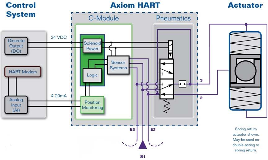
 Solenoid Power (Indicator light): Indicates state of solenoid output (On/Off) Valve position indication: Open or Closed Loop Current: Current flow in 4-20mA")
14 AMI71 Observe / Live Device Variables Valve position (degrees): Current valve position in degrees Air pressure (PSI/BAR): Current Inlet air pressure (PSI or BAR) Temperature (C): Current Temperature of the electronics module (degrees C) Solenoid Power (Indicator light): Indicates state of solenoid output (On/Off) Valve position indication: Open or Closed Loop Current: Current flow in 4-20mA signal wires Valve % open: Indicates how far, in degrees, the valve is open. Cycle count: Number of closed open-closed cycles since last reset 14

15 AMI 71 Historical Data (Trends) Historical Data: These graphs shows the last 16 cycles with the latest cycle on the left. As you accumulate more cycles, the older data is averaged and stored. The red line is the baseline value for this parameter. 15
16 Historical Data (Open Dead time) Open Dead time is defined as the time delay from toggling the solenoid until the valve begins to open. What does this tell me: This value provides a historical look at the time it takes from energizing the coil until the valve starts to move. What could cause it to change: If the open dead time is increasing, that could be caused by partially clogged air lines or by sluggish but functional solenoid coil or spool valve. What can I do to address this: Inspect the air lines for blockages or debris. Inspect / rebuild the spool valve. Inspect the Pilot valve screens for debris. 16
17 Historical Data (Close Dead time) Close Dead time is defined as the time delay from toggling the solenoid until the valve begins to close. What does this tell me: This value provides a historical look at the time it takes from deenergizing the coil until the valve starts to move. What could cause it to change: If the close dead time is rising, that could be caused by partially clogged air lines or by sluggish but functional solenoid coil or spool valve. What can I do to address this: Inspect the air lines for blockages or debris. Inspect / rebuild the spool valve. Inspect the Pilot valve screens for debris. 17
18 Historical Data (Open Breakaway pressure) Open Breakaway Pressure is defined as the pressure differential across the piston at the point where the actuator starts to open the valve. This closely follows breakaway torque and can be used to diagnose problems like sticking valves. What does this tell me: This value provides a historical look at how much pressure differential across the piston is required to begin movement of the actuator/valve from the fully closed position. What could cause it to change: If the Open Breakaway Pressure is rising, breakaway torque is also increasing. This could indicate that a valve is sticking to the seat. What can I do to address this: Valve service may be needed. 18
19 Historical Data (Close Breakaway pressure) Close Breakaway Pressure is defined as the pressure differential across the piston at the point where the actuator starts to close the valve. This closely follows breakaway torque and can be used to diagnose problems like sticking valves. What does this tell me: This value provides a historical look at how much pressure differential across the piston is required to begin movement of the actuator/valve from the fully open position. What could cause it to change: If the Close Breakaway Pressure is rising, breakaway torque is also increasing. This could indicate that a valve is sticking to the seat. What can I do to address this: Valve service may be needed. 19

20 Historical Data (Open time) Open Time is defined as the time it takes for the valve to open. What does this tell me: This value provides a historical look at how long it takes the valve to open. What could cause it to change: If the Open Time is rising, it is simply taking longer for the valve to open. This could indicate that the valve is sticking, or air leakage through the fittings. It could also indicate a sluggish spool valve or pilot valve. What can I do to address this: Valve or actuator service may be needed. Spool valve service may be needed. 20
21 Historical Data (Close time) Close Time is defined as the time it takes for the valve to close. What does this tell me: This value provides a historical look at how long it takes the valve to close. What could cause it to change: If the Close Time is rising, it is simply taking longer for the valve to close. This could indicate that the valve is sticking, or air leakage through the fittings. It could also indicate a sluggish spool valve or pilot valve. What can I do to address this: Valve or actuator service may be needed. Spool valve service may be needed. 21
 during the open cycle.")
22 Historical Data (Open Temperature) Open Temperature is defined as the temperature reading from the temperature transducer inside the electronics module measured when the valve reaches open. What does this tell me: This value provides a historical look at the temperature seen by the Axiom's C-module (Electronics module) during the open cycle. What could cause it to change: Ambient temperature fluctuations or internal heat rise. What can I do to address this: If the temperatures exceed the temperature rating of the device, life of the device could be reduced. Consider heaters / coolers or insulating the surrounding pipes/tanks to protect electronics from exposure to temperatures they are not designed to handle. 22
23 Historical Data (Close Temperature) Close Temperature is defined as the temperature reading from the temperature transducer inside the electronics module measured when the valve reaches closed. What does this tell me: This value provides a historical look at the temperature seen by the Axiom's C-module (Electronics module) during the closed cycle. What could cause it to change: Ambient temperature fluctuations or internal heat rise. What can I do to address this: If the temperatures exceed the temperature rating of the device, life of the device could be reduced. Consider heaters/coolers or insulating the surrounding pipes/tanks to protect electronics from exposure to temperatures they are not designed to handle. 23

24 Historical Data (Close Setpoint Change) Close Setpoint Change is defined as the amount the closed setpoint has changed. This parameter can indicate problems such as valve seat wear or buildup. What does this tell me: This value provides a historical look at the amount the closed position setpoint has been changed. The setpoint is set by the user. This shows how much it has changed over time. What could cause it to change: Only users can change this, either with the onboard push buttons or in the configuration screen. If the users are changing the setpoint they could be doing so because they are no longer reaching the desired setpoint. (overtravel or undertravel) If the setpoint is not being reached, this could indicate that the actual valve travel has changed. What can I do to address this: This could be caused by worn seats or buildup in the valve. Valve service may be needed. 24
25 AMI 71 Installation 25

26 AMI 71 Installation 26

 - Download DTM (Device Type Manager) from www.")
27 Asset Management Systems Using systems that accept EDDL (Electronic Device Description Language) - Download EDD from - Typical EDDL compatible asset management systems include: Emerson AMS Siemens PDM Honeywell FDM Using systems that run FDT (Field Device Tool) - Download DTM (Device Type Manager) from - DTM is loaded into FDT frame program which is part of DCS or a separate PC - Typical FDT compatible systems include Honeywell FDM FieldCare Yokogawa PRM ABB AVM 27
28 Axiom Detect automated valve problems... before they shut down your process
Series 3730 and Series 3731 EXPERTplus Valve Diagnostics with Partial Stroke Test (PST)
") Series 3730 and Series 3731 EXPERTplus Valve Diagnostics with Partial Stroke Test (PST) Application Positioner firmware for early detection of control valve faults giving maintenance recommendations. Valid
Series 3730 and Series 3731 EXPERTplus Valve Diagnostics with Partial Stroke Test (PST) Application Positioner firmware for early detection of control valve faults giving maintenance recommendations. Valid
Data Sheet T 8389 EN. Series 3730 and 3731 Types , , , and. EXPERTplus Valve Diagnostic
 Data Sheet T 8389 EN Series 3730 and 3731 Types 3730-2, 3730-3, 3730-4, 3730-5 and Type 3731-3 Electropneumatic Positioners EXPERTplus Valve Diagnostic Application Positioner firmware to detect potential
Life Cycle Benefits: Maintenace (Control Valve Diagnostic and Field Device Diagnostic Management)
") Life Cycle Benefits: Maintenace (Control Valve Diagnostic and Field Device Diagnostic Management) Yasushi Kudo Yamatake Corporation Aaron Chen Azbil Taiwan Contents I. Prologue II. Possibilities of CV
Life Cycle Benefits: Maintenace (Control Valve Diagnostic and Field Device Diagnostic Management) Yasushi Kudo Yamatake Corporation Aaron Chen Azbil Taiwan Contents I. Prologue II. Possibilities of CV
BUBBLER CONTROL SYSTEM
 BUBBLER CONTROL SYSTEM Description: The HDBCS is a fully automatic bubbler system, which does liquid level measurements in water and wastewater applications. It is a dual air compressor system with, air
USER MANUAL. Intelligent Diagnostic Controller IDC24-A IDC24-AF IDC24-AFL IDC24-F IDP24-A * IDP24-AF * IDP24-AFL * IDP24-F * 1/73
 USER MANUAL Intelligent Diagnostic Controller IDC24-A IDC24-AF IDC24-AFL IDC24-F IDP24-A * IDP24-AF * IDP24-AFL * IDP24-F * *) Require software ID: DID-SW-001 1/73 Table of contents 1 General... 3 1.1
The benefits of the extended diagnostics feature. Compact, well-proven, and flexible
 ABB MEASUREMENT & ANALYTICS TECHNICAL INFORMATION PositionMaster EDP300 Extended Diagnostics Compact, well-proven, and flexible The benefits of the extended diagnostics feature The PositionMaster EDP300
BUBBLER CONTROL SYSTEM
 BUBBLER CONTROL SYSTEM Description: The LDBCS is a fully automatic bubbler system, which does liquid level measurements in water and wastewater applications. It is a dual air compressor system with, air
2600T Series Pressure Transmitters Plugged Impulse Line Detection Diagnostic. Pressure Measurement Engineered solutions for all applications
 Application Description AG/266PILD-EN Rev. C 2600T Series Pressure Transmitters Plugged Impulse Line Detection Diagnostic Pressure Measurement Engineered solutions for all applications Increase plant productivity
Specifications and information are subject to change without notice. Up-to-date address information is available on our website.
 www.smar.com Specifications and information are subject to change without notice. Up-to-date address information is available on our website. web: www.smar.com/contactus.asp FY302 AssetView IHM FY302 -
Partial Stroke Testing for SRD991 and SRD960
 Technical Information 09.11 TI EVE0105 PST-(en) Partial Stroke Testing for SRD991 and SRD960 Final control elements in Emergency Shutdown (ESD) applications such as ON-OFF-, Blow Down and Venting-Valves
Positioner type Smart Valve Positioner with diagnostic functions. Presented By: Mr. Gourishankar Saharan. Product management Jens Bargon / V42
 Positioner type 3730-5 Smart Valve Positioner with diagnostic functions Presented By: Mr. Gourishankar Saharan Product management Jens Bargon / V42 Product overview P Process V Valves l Control Valves
Model EXAxt AV550G. Averaging Oxygen Analyzer
 Model EXAxt AV550G Averaging Oxygen Analyzer Oxygen Measurement and Flyash Oxygen % vs cell EMF The O2 mation, model AV550, averaging oxygen analyzer was designed with a focus Calibration 1 on practical
ACV-10 Automatic Control Valve
 ACV-10 Automatic Control Valve Installation, Operation & Maintenance General: The Archer Instruments ACV-10 is a precision automatic feed rate control valve for use in vacuum systems feeding Chlorine,
Time-Delay Electropneumatic Applications
 Exercise 3-4 EXERCISE OBJECTIVE & & & To introduce time delays; To describe the operation of a time-delay valve; To describe the operation of a time-delay relay. DISCUSSION Time-Delays Time delays are
PositionMaster EDP300 Extended Diagnostics. Compact, well-proven, and flexible
 Change from one to two columns Technical Information TI/EDP300_ED-EN Rev. A PositionMaster EDP300 Extended Diagnostics Compact, well-proven, and flexible The benefits of the extended diagnostics feature
A Planning Guide for Effective Use HART Implementations. December 2012 (D103278X012)
") FIELDVUE Instruments A Planning Guide for Effective Use HART Implementations December 2012 (D103278X012) You've purchased a FIELDVUE instrument...now what??? How do you get the most value out of it? Where
FIELDVUE Instruments A Planning Guide for Effective Use HART Implementations December 2012 (D103278X012) You've purchased a FIELDVUE instrument...now what??? How do you get the most value out of it? Where
PREDICTING HEALTH OF FINAL CONTROL ELEMENT OF SAFETY INSTRUMENTED SYSTEM BY DIGITAL VALVE CONTROLLER
 PREDICTING HEALTH OF FINAL CONTROL ELEMENT OF SAFETY INSTRUMENTED SYSTEM BY DIGITAL VALVE CONTROLLER Riyaz Ali FIELDVUE Business Development Manager Fisher Controls Int'l., LLC. Marshalltown, IA 50158
FLUID POWER FLUID POWER EQUIPMENT TUTORIAL OTHER FLUID POWER VALVES. This work covers part of outcome 2 of the Edexcel standard module:
 FLUID POWER FLUID POWER EQUIPMENT TUTORIAL OTHER FLUID POWER VALVES This work covers part of outcome 2 of the Edexcel standard module: UNIT 21746P APPLIED PNEUMATICS AND HYDRAULICS The material needed
TECHNICAL DATA SINGLE INTERLOCKED PREACTION SYSTEM WITH PNEUMATIC RELEASE
 1 of 10 1. DESCRIPTION (Refer to Figures 1-3.) Viking supervised Single Interlocked Preaction Systems utilize a Viking Deluge Valve and a pneumatically pressurized automatic sprinkler system. The system
Touch Screen Guide. OG-1500 and OG Part # T011
 Touch Screen Guide OG-1500 and OG-2000 Part # 9000000.T011 Effective 11/2010 External View Internal View 1. Transducer Banks 2. Oxygen Sensor 3. PLC These are the two manifolds with three (3) transducers
Competence in Functional Safety
 MANUAL Competence in Functional Safety Safety-instrumented system Instrumentation Automation SMART IN FLOW CONTROL. SAMSON AIR TORQUE CERA SYSTEM KT-ELEKTRONIK LEUSCH PFEIFFER RINGO SAMSOMATIC STARLINE
Operating Instructions EB EN. Series 373x Electropneumatic Positioner Type 373x-5 EXPERT + with FOUNDATION fieldbus communication
 Series 373x Electropneumatic Positioner Type 373x-5 EXPERT + with FOUNDATION fieldbus communication Fig. 1 Valve diagnostics with TROVIS-VIEW Operator Interface Operating Instructions EB 8388-5 EN Firmware
Neles ValvGuard VG9000H Rev 2.0. Safety Manual
 Neles ValvGuard VG9000H Rev 2.0 Safety Manual 10SM VG9000H en 11/2016 2 Neles ValvGuard VG9000H Rev 2.0 Safety Manual Table of Contents 1 General information...3 1.1 Purpose of the document... 3 1.2 Description
EXPERIMENT 1 AIR PRESSURE CONTROL SYSTEM
 EXPERIMENT 1 AIR PRESSURE CONTROL SYSTEM 1.0 OBJECTIVE To study the response of gas pressure control using PID controller. 2.0 INTRODUCTION TO THE APPARATUS a) The process plant consists of two air vessels
A TECHNICAL REFERENCE
 A TECHNICAL REFERENCE FOR CAREL DCM CONTROLLERS DIGITAL COMPRESSOR MODULE CANADIAN HEAD OFFICE AND FACTORY USA HEAD OFFICE AND FACTORY CANADIAN EASTERN FACTORY 1401 HASTINGS CRES. SE CALGARY, ALBERTA T2G
TR Electronic Pressure Regulator. User s Manual
 TR Electronic Pressure Regulator Page 2 of 13 Table of Contents Warnings, Cautions & Notices... 3 Factory Default Setting... 4 Quick Start Procedure... 5 Configuration Tab... 8 Setup Tab... 9 Internal
INSTALLATION OPERATION MAINTENANCE
 Bermad Electrically Controlled On-Off Deluge Valve Model: 400E-3D INSTALLATION OPERATION MAINTENANCE Application Engineering BERMAD 1. Safety First BERMAD believes that the safety of personnel working
2600T Series Pressure Transmitter Models 264DC Differential and 264HC Gage Level Transmitters. Kent-Taylor
 INDUSTRIAL INSTRUMENTS AND CONTROLS SPECIALIST Kent-Taylor 2600T Series Pressure Transmitter Models 264DC Differential and 264HC Gage Level Transmitters Features Include Base accuracy : ±0.075% Span limits
Electrical Solutions Corporation 2368 Eastman Ave, Suite 13, Ventura, CA Phone (805) ~ Fax (805)
 ~ Fax (805)") Gas Chromatograph Operation Gas Company GC Initial setup - 6 Feb 2007 The Gas Company Gas Chromatograph (GC) data now come into Wonderware and can be accessed from the Gas Chrom button on the Wonderware
Gas Chromatograph Operation Gas Company GC Initial setup - 6 Feb 2007 The Gas Company Gas Chromatograph (GC) data now come into Wonderware and can be accessed from the Gas Chrom button on the Wonderware
Service Test Unit for ROSS Proportional Valves RESK
 Service Unit for Proportional Valves Page 1 Technical Description ROSS 04.08.2015 Service Test Unit for ROSS Proportional Valves Technical Description V 1.0 / 2015 RESK 4591.40 For all Prop Valve Models
SSL. Smart Valve Positioner.
 Smart Valve Positioner Smartest valve control device meeting a dynamic performance and a precise setting with a piezoelectric technology and an optimized auto-calibration program Features Auto-Calibration
Valve Communication Solutions. Safety instrumented systems
 Safety instrumented systems Safety Instrumented System (SIS) is implemented as part of a risk reduction strategy. The primary focus is to prevent catastrophic accidents resulting from abnormal operation.
Four common PRESSURE CALIBRATION PAIN POINTS
 Four common PRESSURE CALIBRATION PAIN POINTS Pressure calibration is often critical to process control systems, helping to optimize operations and ensure plant safety. While pressure instrumentation can
RESILIENT SEATED BUTTERFLY VALVES FUNCTIONAL SAFETY MANUAL
 Per IEC 61508 and IEC 61511 Standards BRAY.COM Table of Contents 1.0 Introduction.................................................... 1 1.1 Terms and Abbreviations...........................................
Fisher DVI Desuperheater Venturi Inline
 Instruction Manual DVI Desuperheater Fisher DVI Desuperheater Venturi Inline Contents Introduction... 1 Scope of Manual... 1 Description... 1 Principle of Operation... 2 Installation... 3 Operating Instructions...
The Discussion of this exercise covers the following points:
 Exercise 5-3 Wet Reference Leg EXERCISE OBJECTIVE Learn to measure the level in a vessel using a wet reference leg. DISCUSSION OUTLINE The Discussion of this exercise covers the following points: Measuring
Device Description User Manual Logix 520MD Positioners
 Device Description User Manual Logix 520MD Positioners GENERAL INFORMATION... 3 INTRODUCTION... 3 QUALIFIED PERSONNEL... 3 USING THIS DOCUMENT... 3 TERMS CONCERNING SAFETY... 3 1 STATUS... 4 1.1 CMD SOURCE...
The Ins and Outs of I/P Transducers
 The Ins and Outs of I/P Transducers By Mark B. Levine, ControlAir Inc. General description I/P transducers are versatile instruments that use an electrical control signal to proportionally regulate gas
PART 5 - OPTIONS CONTENTS 5.1 SYSTEM EXPANSION 5-3
 PART 5 - OPTIONS CONTENTS Para Page 5.1 SYSTEM EXPANSION 5-3 5.2 SENSORS 5-3 5.2.1 Trim Angle Sensor 5-3 5.2.2 Mast Rotation Sensor 5-3 5.2.3 Heel Angle Sensor 5-3 5.2.4 Barometric Pressure Sensor 5-3
ATM 322 Basic Pneumatics H.W.6 Modules 5 7
 ATM 322 Basic Pneumatics H.W.6 Modules 5 7 Name: Answer Key Mark: Question I: Write (T) for True and (F) for false sentences. A) For the time dependant process control; Step enabling conditions are generated
MWEA MAINTENANCE SEMINAR SPECIALTY VALVES POWER GLOBES
 MWEA MAINTENANCE SEMINAR SPECIALTY VALVES POWER GLOBES J O H N G. H U N T E R Types of Valves P A U L M A R C H I Accessories Principals of Operation Maintenance Control Valve Types Common Problems Key
Double whammy: the benefits of valve signatures and partial stroke testing
 Double whammy: the benefits of valve signatures and partial stroke testing By Paul Gruhn, P.E., C.F.S.E., L&M Engineering and Derek Essam, Drallim Abstract Many papers have been written over the past five
Fisher FIELDVUE DVC6200f Digital Valve Controller PST Calibration and Testing using ValveLink Software
 Instruction Manual Supplement DVC6200f Digital Valve Controller Fisher FIELDVUE DVC6200f Digital Valve Controller PST Calibration and Testing using ValveLink Software The test procedure contained in this
Ultima. X Series Gas Monitor
 Ultima X Series Gas Monitor Safety Manual SIL 2 Certified " The Ultima X Series Gas Monitor is qualified as an SIL 2 device under IEC 61508 and must be installed, used, and maintained in accordance with
A4s Operation Manual
 A4s Operation Manual Safety Instruction Please read this manual carefully, also with related manual for the machinery before use the controller. For installing and operating the controller properly and
4.5 Diagnosis Diagnosticdisplay. Operation
 4.5 Diagnosis 4.5.1 Diagnosticdisplay No. Abbreviation Meaning To access the diagnostic display in automatic or manual mode, press all three buttons for at least two seconds. Thisfollowingtablegivesanoverviewofthevaluesthatcanbe
TECHNICAL DATA. Q = C v P S
 Page 1 of 13 1. DESCRIPTION The Viking 6 Model G-6000 Dry Valve Riser Assembly consists of a small profile, light weight, pilot operated valve that is used to separate the water supply from the dry sprinkler
Additel761 Series Firmware Updates
 Additel761 Series Firmware Updates 2018-09-03 APC V01.XX Vertions before APC V01.03(Included) APC V01.04 APC V01.05 APC V01.06 APC V01.07 APC V01.08 APC V01.09 APC V01.10 APC V01.11 APC V01.12 APC V01.13
Fisher DSA Steam-Atomized Desuperheater
 Instruction Manual DSA Desuperheater Fisher DSA Steam-Atomized Desuperheater Contents Introduction... 1 Scope of Manual... 1 Description... 1 Principle of Operation... 2 Installation... 2 Operating Instructions...
ACCURATE PRESSURE MEASUREMENT FOR STEAM TURBINE PERFORMANCE TESTING
 ACCURATE PRESSURE MEASUREMENT FOR STEAM TURBINE PERFORMANCE TESTING Blair Chalpin Charles A. Matthews Mechanical Design Engineer Product Support Manager Scanivalve Corp Scanivalve Corp Liberty Lake, WA
Universal Valve Company Inc
 Universal Valve Company Inc 800-223-0741 www.universalvalve.com 1975-FA34 (Air Tower Troubleshooting Manual) Overview This manual has been arranged as a tool for diagnosing, and repairing Free Air Universal
TECHNICAL DATA. Q = C v P S
 January 6, 2012 Preaction 348a 1. Description Viking supervised Surefire Preaction Systems utilize the Viking G-6000P Valve. The small profile, lightweight, pilot operated Viking G-6000P Valve comes complete
INSTALLATION & MAINTENANCE INSTRUCTIONS
 DESCRIPTION / IDENTIFICATION The QBX series valve uses Proportion-Air closed loop technology for Pressure control. It gives an output pressure proportional to an electrical command signal input. The QB1X
I T T Pressure Reducing Valve WARNING INSTALLATION, OPERATION, AND MAINTENANCE MANUAL
 INSTALLATION, OPERATION, AND MAINTENANCE MANUAL I-867-4T 867-4T Pressure Reducing Valve HANG THESE INSTRUCTIONS ON THE INSTALLED VALVE FOR FUTURE REFERENCE WARNING Read and understand all instructions
SSR. Smart Valve Positioner.
 Smart Valve Positioner Smartest valve control device meeting a dynamic performance and a precise setting with a piezoelectric technology and an optimized auto-calibration program Features Auto-Calibration
Simple Set. Pressure Independent Control Valves 2 Way 1/2-2
 The Bray Simple Set is a threaded pressure independent control (PIC) valve designed for a wide variety of hot water and chilled water control applications. The SS Series combines high rangeability control
MP15 Jockey Pump Controller
 Setup and Operating Instructions MP15 Jockey Pump Controller This manual provides general information, installation, operation, maintenance, and system setup information for Metron Model MP15 Jockey Pump
Automatic Valve Proving Control
 ISO 9001 Automatic Valve Proving Control 7 696 LDU11 UL recognized FM approved Features Performs leak test of the gas shut-off valves before start-up and/or immediately after burner shut-down No inlet
Controlling the prefeeder
 Controlling the prefeeder A prefeeder is a modulating device of some kind, controlling the material flow into the belt feeder infeed. You need it for three reasons: 1. The material can not be sheared at
Richards Industries Basic Siemens PS2 Positioner Functions
 Basic Siemens PS2 Positioner Functions Wiring 1 Supply Pressure Use clean, dry instrument air for the supply pressure. In general, on valves that are normally closed, you need 35-40 psi of supply pressure
WATER CONTROL SYSTEM QUICK START
 SETTINGS MENU SYSTEM OPTIONS WATER LEVEL BAR GRAPH 3 DS SPRAY ON/OFF CS SPRAY ON/OFF BEACON WATER CONTROL SYSTEM QUICK START WWW.GFWORLDWIDE.COM +1 (208) 664-9291 SERVICE@GFWORLDWIDE.COM DISPLAY SCREEN
User Manual for the Mars Calibration Bench
 User Manual for the Mars Calibration Bench Fall 2013 Table of Contents Table of Contents Table of Contents... iii Introduction... v Chapter 1: The Mars Calibration Bench... 1 What Is the Mars Calibration
Design DSA Steam-Atomized Desuperheater
 Instruction Manual DSA Desuperheater Design DSA Steam-Atomized Desuperheater Contents Introduction............................... 1 Scope of Manual......................... 1 Description..............................
Section 4: Sequence valve adjustments
 Section 4: Sequence valve adjustments 290509 For models 40 / 45 / 45R / 50 / 60 Jan 30 2014 - Page Sequence valve manifold (pic) 2 Sequence valve overview 2 Sequence valve manifold flow chart 3 Trouble
TANK MANAGER FOR TWO TANKS OPERATING MANUAL. 10/31/11 C-More T6C L color touch panel
 TANK MANAGER FOR TWO TANKS OPERATING MANUAL 10/31/11 C-More T6C L color touch panel 1 TABLE OF CONTENTS GENERAL...3 INSTALLATION...4 STONE TEST PROCEDURE...7 OPERATIONAL SUMMARY...7 AUTO CARBONATION...10
OPERATING INSTRUCTIONS Pressure Control System PCS-20 through PCS-100
 107 W. Main Street Worthington, PA 16262 Phone: 724.297.3416 Fax: 724.297.5189 http://www.airtak.com OPERATING INSTRUCTIONS Pressure Control System PCS-20 through PCS-100 12-2007 TABLE OF CONTENTS PAGE
700 SERIES BMS II BUBBLER MONITORING SYSTEM
 1 700 SERIES BMS II BUBBLER MONITORING SYSTEM VISIT OUR WEBSITE AT SIGMACONTROLS.COM 700 SERIES BMS II MANUAL 062114 2 TABLE OF CONTENTS INTRODUCTION 3 Physical Specifications WIRING 5 PROGRAMMING & SETUP..
Burner Management System DEMO Operating instructions
 Burner Management System DEMO Operating instructions Burner Management System DEMO Operating Instructions Startup Summary - Normal startup is accomplished in four basic steps: 1. Leak Test a. Safety Valve
EL-O-Matic E and P Series Pneumatic Actuator SIL Safety Manual
 SIL Safety Manual DOC.SILM.EEP.EN Rev. 0 April 2017 EL-O-Matic E and P Series Pneumatic Actuator SIL Safety Manual schaal 1:1 EL Matic TM EL-O-Matic E and P Series DOC.SILM.EEP.EN Rev. 0 Table of Contents
IMVS2000v2 INSTALLATION OPERATING MANUAL MAN720. Integrated Monitoring Valve System. Copyright by BIFFI ITALIA. All rights reserved.
 IMVS2000v2 Integrated Monitoring Valve System INSTALLATION OPERATING MANUAL MAN720 Copyright by BIFFI ITALIA. All rights reserved. 1 4 11/02/2019 Fifth Issue Piacenti Battaglia 3 04/10/2018 Fourth Issue
LENNOX SLP98UHV DIAGNOSTIC CODES
 Code Status of Equipment Action required to clear and recover - Idle mode (Decimal blinks at 1 Hertz -- 0.5 second ON, 0.5 second OFF) A Cubic feet per minute (cfm) setting for indoor blower (1 second
Smart performance with innovative and ever-strong coil drive even under harsh working environments
 Smart Valve Positioner SS2 inear / Rotary Smart performance with innovative and ever-strong coil drive even under harsh working environments Easy and quick auto-calibration Detecting RA (reverse acting)
VR46.5V(A)/VR86.5V(A) SERIES
/VR86.5V(A) SERIES") VR46.5V(A)/VR86.5V(A) SERIES COMACT COMBINATION GAS CONTROS WITH INTEGRATED 1:1 GAS/AIR REGUATOR FOR AUTOMATIC IGNITION SYSTEMS SECIFICATIONS INSTRUCTION SHEET Subject to change without notice. rinted
VR46.5V(A)/VR86.5V(A) SERIES COMACT COMBINATION GAS CONTROS WITH INTEGRATED 1:1 GAS/AIR REGUATOR FOR AUTOMATIC IGNITION SYSTEMS SECIFICATIONS INSTRUCTION SHEET Subject to change without notice. rinted
INSTALLATION & MAINTENANCE INSTRUCTIONS DESCRIPTION SPECIFICATIONS. CE (EMC) Compliant
 Compliant") INSTALLATION & MAINTENANCE INSTRUCTIONS DESCRIPTION The QB3 is a closed loop pressure regulator consisting of two solenoid valves, internal pressure transducer, and electronic controls mounted to an integrated
INSTALLATION & MAINTENANCE INSTRUCTIONS DESCRIPTION The QB3 is a closed loop pressure regulator consisting of two solenoid valves, internal pressure transducer, and electronic controls mounted to an integrated
QBS Electronic Pressure Regulator
 INSTALLATION AND MAINTENANCE INSTRUCTIONS DESCRIPTION / IDENTIFICATION The QBS stainless steel series is an electronically controlled pressure regulator. The QBS controls the pressure on its output port
Beyond Switches for Pump Monitoring:
 Beyond Switches for Pump Monitoring: What Changed with API Standard 682 Beyond Switches for Pump Monitoring: What Changed with API Standard 682 API Standard 682 (Plans 52, 53 A, B, and C for dual seal
TECHNICAL DATA 3 MODEL G-3000 DRY VALVE RISER ASSEMBLY
 Page 1 of 13 1. DESCRIPTION The Viking 3 Model G-3000 Dry Valve Riser Assembly is equipped with a small profile, light weight, pilot operated valve that is used to separate the water supply from the dry
ISQB1 INTRINSICALLY SAFE ELECTRO-PNEUMATIC CONTROL VALVE INSTALLATION & MAINTENANCE INSTRUCTIONS HAZARDOUS AREA CLASSIFICATION
 PROPORTION AIR ISQB1 INTRINSICALLY SAFE ELECTRO-PNEUMATIC CONTROL VALVE INSTALLATION & MAINTENANCE INSTRUCTIONS Hazardous area classification Description / identification General specifications Connection
TECHNICAL DATA. System water supply pressure enters the priming chamber of the deluge valve (A.1) through the 1/4 (8 mm) priming line, which
 through the 1/4 (8 mm) priming line, which") January 27, 2012 307a 1. (Refer to Figures 1-3.) A Viking Non-Interlocked Preaction system utilizes a Viking Deluge Valve to control water flow into system piping equipped with closed sprinklers. Under
January 27, 2012 307a 1. (Refer to Figures 1-3.) A Viking Non-Interlocked Preaction system utilizes a Viking Deluge Valve to control water flow into system piping equipped with closed sprinklers. Under
Connect with Confidence NO POWER NO PROBLEM
 Connect with Confidence NO POWER NO PROBLEM The ideal solution to implement wireless sensor monitoring in IoT applications where power is not available. At last, there s a roll-out ready way to implement
TECHNICAL DATA. Q = C v P S
 January 6, 2012 Preaction 333a 1. Description Viking supervised Surefire Preaction Systems Utilize the Viking G-3000P Valve. The small profile, lightweight, pilot-operated Viking G-3000P Valve comes complete
TECHNICAL DATA. Q= Cv S
 Page 1 of 13 1. DESCRIPTION The Viking 4 inch Model G-4000 Dry Valve Riser Assembly consists of a small profile, light weight, pilot operated valve that is used to separate the water supply from the dry
A4 Operation Manual. Fig.1-1 Controller Socket Diagram
 A4 Operation Manual Safety Instruction Please read this manual carefully, also with related manual for the machinery before use the controller. For installing and operating the controller properly and
TECHNICAL DATA Q = C. v P S. 2 Model G-2000 Dry valve. Page 1 of 13
 Page 1 of 13 1. Description The Viking 2 Model G-2000 Dry Valve Riser Assembly consists of a small profile, light weight, pilot operated valve that is used to separate the water supply from the dry sprinkler
Electropneumatic Transducer (I/P) Installation, Operation and
 Installation, Operation and") Nitra NCP1 Series Electropneumatic Transducer (I/P) Installation, Operation and Maintenance Instructions Ordering Information Contents Part Number I/P Transducers Output Range Input psig bar Section Description
Nitra NCP1 Series Electropneumatic Transducer (I/P) Installation, Operation and Maintenance Instructions Ordering Information Contents Part Number I/P Transducers Output Range Input psig bar Section Description
CHEMICAL ENGINEERING LABORATORY CHEG 239W. Control of a Steam-Heated Mixing Tank with a Pneumatic Process Controller
 CHEMICAL ENGINEERING LABORATORY CHEG 239W Control of a Steam-Heated Mixing Tank with a Pneumatic Process Controller Objective The experiment involves tuning a commercial process controller for temperature
MODEL RCW NON-INTERLOCK PREACTION SYSTEM
 0 Airpark Dr. Standish, MI 8658 989-86-58 www.globesprinkler.com Technical Support 989--00 techservice@globesprinkler.com MODEL RCW NON-INTERLOCK PREACTION SYSTEM GENERAL DESCRIPTION The Globe Model RCW
Universal Valve Company Inc
 1975-FA34 (Air Tower Troubleshooting Manual) Overview This manual has been arranged as a tool for diagnosing, and repairing Universal Air Towers Please read closely to identify the components that are
WATCH COLLECTION NG701 SERIES INSTRUCTION MANUAL
 WATCH COLLECTION NG701 SERIES INSTRUCTION MANUAL INTRODUCTION This watch features electronic sensors that measure outdoor conditions such as temperature, pressure, and altitude. The watch provides essential
Model: 720-UL INSTALLATION OPERATION MAINTENANCE. Bermad Pressure Reducing Valve IOM. Model: FP -720-UL Sizes: 2"-12" BERMAD. Application Engineering
 Bermad Pressure Reducing Valve Model: 720-UL INSTALLATION OPERATION MAINTENANCE Application Engineering BERMAD 1. Safety First BERMAD believes that the safety of personnel working with and around our equipment
Bermad Pressure Reducing. Model: 42T
 Bermad Pressure Reducing Pilot Operated Pressure Control Valve Model: 42T Installation Operation Maintenance Manual (IOM) REV. 27.7.17 Page 1 of 12 Safety First BERMAD believes that the safety of personnel
Standard Chiller 1/4 compressors Manual version: /10/96
 Application program for Macroplus II Standard Chiller 1/4 compressors Manual version: 1.4-18/10/96 Program code: EP000ECH02 Rif.: 68EM Contents 0$,1)($785(6 HARDWARE...2 FUNCTIONS OF THE SYSTEM...3 PROTECTIONS...3
SINGLE VALVE WITH LOW-FLOW BYPASS
 CONTROL VALVES Pressure Reducing Valve Sizing Guide Sizing pilot operated reducing valves is not a complicated process. It starts with determining requirements and following these guidelines in valve size
Control Valve Training Course Program
 Control Valve Training Course Program FINAL CONTROL AND REGULATE Control Valves LEARNINGPATH At the foundation of any process are the field devices that measure and control the flow of air, steam, water,
Exercise 5-2. Bubblers EXERCISE OBJECTIVE DISCUSSION OUTLINE. Bubblers DISCUSSION. Learn to measure the level in a vessel using a bubbler.
 Exercise 5-2 Bubblers EXERCISE OBJECTIVE Learn to measure the level in a vessel using a bubbler. DISCUSSION OUTLINE The Discussion of this exercise covers the following points: Bubblers How to measure
Specifications and information are subject to change without notice. Up-to-date address information is available on our website.
 www.smar.com Specifications and information are subject to change without notice. Up-to-date address information is available on our website. web: www.smar.com/contactus.asp LD302 - AssetView HMI LD302
CP3R Quick Start Manual
 RUN MON PRM PU EXT NET RUN D700 3 200V RUN MON PRM PU EXT NET RUN D700 3 200V CP3R Quick Start Manual for Constant Pressure Applications This CP3R Drive has been factory pre-programmed for your specific
OXY Integral. INTERCON ENTERPRISES INC Tel: Fax: Internet:
 OXY Integral INTERCON ENTERPRISES INC Tel: 800 665 6655 Fax: 604 946 5340 E-Mail: sales@intercononline.com Internet: www.intercononline.com Manual Integral 2006 1 INDEX 2-3 PREFACE 4 INTRODUCTION 5 Principle
CONTROL VALVE TESTING
 The optimal functioning of the Control valve not only exists of sufficient body & seat tightness, but more important, the total "performance" of the valve and its controls! For an accurate and reliable
Using Modbus Protocol with the ALTUS Net Oil Computer. Instruction Manual
 Using Modbus Protocol with the ALTUS Net Oil Computer Instruction Manual November 2000 Using Modbus Protocol with the ALTUS Net Oil Computer Instruction Manual November 2000 For technical assistance,