MiniPurge Type Z(Y) LC Manual ML 447
|
|
|
- Warren Moody
- 6 years ago
- Views:
Transcription
 Systems 2. Application Suitability 3.")

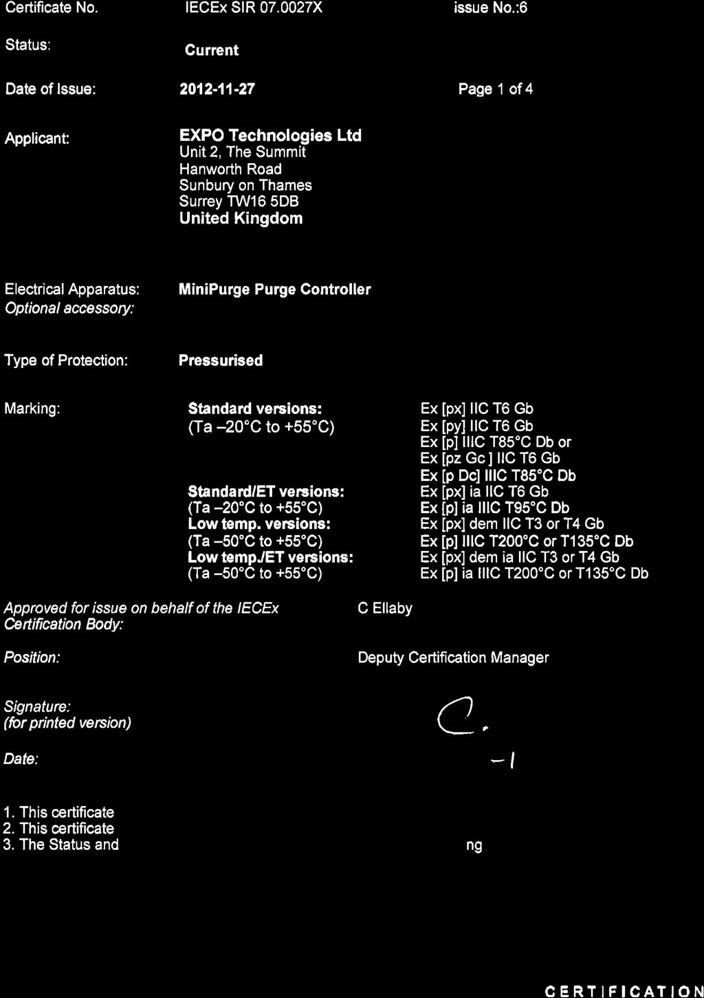
1 MiniPurge Type Z(Y) LC Manual ML 447 This manual covers Mini-Z(Y)-Purge Leakage Compensation Sizes: 1, 2 & 3 Mounting Options: bp, pm, nm, ss Output Options: IS, PO CONTENTS: 1. Specification Sheet MiniPurge Type Z(Y) Systems 2. Application Suitability 3. Installation, Operation and Maintenance for LC Systems Section 0. Description and Principle of Operation Section 1. Installation of the System Section 2. Operation of the System Section 3. Maintenance of the System Section 4. Fault Finding - LC Systems Section 5. Annex of Options Fitted 4. Drawings 5. Certificates ML447 v17 26-Nov-14
2 1. Specification Sheet MiniPurge Type Z(Y) Systems Model No. (Example): 07 1 ZLC / ss / IS (Note: Not all codes are applicable) Purge System Type 07 = MiniPurge Size 1 = Sub MiniPurge Purge flow rate 8 scfm, 225 Nl / min 2 = MiniPurge Purge flow rate 16 scfm, 450 Nl /min 3 = Super MiniPurge Purge flow rate 32 scfm, 900 Nl/min Approval / Certification Z = Y = Europe EN , EN , EN Sira 01ATEX1295X 0518 II 3 (2) G D 0518 II 2 (2) G D Ex [pz Gc] IIC T6 Gb Ex [py] II T6 Gb Ex [p Dc] IIIC T85ºC Ex [p] IIIC T85ºC Db T amb -20ºC +55ºC T amb -20ºC +55ºC IEC IEC , IEC , IEC IECEx SIR X Ex [pz Gc] IIC T6 Gb Ex [py] II T6 Gb Ex [p Dc] IIIC T85ºC Ex [p] IIIC T85ºC Db T amb -20ºC +55ºC T amb -20ºC +55ºC USA / Canada NFPA 496 FM 1X8A4AE Class I Div 2 Class I Div 1 Groups A, B, C & D Groups A, B, C & D UL E Class I Div 2 Class I Div 1 Groups A, B, C & D Groups A, B, C & D Brazil INMETRO - TUV TÜV X Ex [pz Gc] IIC T6 Gb Ex [p Dc] IIIC T85ºC Db -20ºC Ta +55ºC Ex [py] IIC T6 Gb Ex [p] IIIC T85ºC Db -20ºC Ta +55ºC Alarm (Signals) IS = PO = Internal Switch Alarm : Dry, VFC,SPSTN/O Contact NI Ex na Non-Incendive Circuits V max < 254 Vac rms I max < 1 A P max = 70 W IS Ex i circuits U max = 30 Vdc I max = 350 ma C i = 0 L i = 0 Hermetically Sealed Switch Ex m IIC T4 Gc V max = 254 Vac rms I max 0.7 A Pneumatic Output Alarm : Loss of Pressure = No signal Pressurized = at supply pressure MiniPurge Housing bp = pm = nm = ss = Back Plate (Top/Side Mount) 316L Stainless Steel (NROB finish) Panel Mount (Side/Front Mount) 316L Stainless Steel (NROB finish) Non Metallic (Top/Side Mount) Polystyrene c/w clear cover 316L Stainless Steel (NROB finish) Neoprene Top Mount Gasket Purging Method LC = Leakage Compensation For limitations and conditions of use refer to the applicable certificate at the back of this manual. Supply Pressure Flow & Pressure Sensors "Low Pressure Sensor" "Flow Sensor" Leakage Compensation : 60 psi / 0.4MPa / 4 barg must be regulated at inlet. Maximum supply pressure 115 psi / 0.8MPa / 8 barg. Compressed Air / Nitrogen : 0.2 "WC / 50 Pa (0.5 mbarg) : 1.1 "WC / 280 Pa (2.8 mbarg) : Size 1: Variable up to 2 scfm (60 Nl/min) to compensate for Enclosure Leakage : Size 2: Variable up to 9 scfm (250 Nl/min) to compensate for Enclosure Leakage : Size 3: Variable up to 28.3 scfm (800 Nl/min) to compensate for Enclosure Leakage Relief Valve MiniPurge Size 1 MiniPurge Size 2 MiniPurge Size 3 Model No RLV25/ss/FS RLV36/ss/FS RLV52/ss/FS Opening Pressure : 4 WC / 1 kpa (10 mbarg) Material : 316L Stainless Steel, Spark Arrestor: Stainless Steel mesh, Neoprene Gasket Action on Loss of Pressure : ALARM ONLY ML447 v17 26-Nov-14
3 2. Application Suitability MiniPurge Systems are certified for use in Hazardous Areas, where the Hazardous Area is non-mining (i.e. above ground) and the hazard is caused by flammable gasses, vapours or dust. Mini-Z-Purge Systems may be used in IECEx, ATEX Zone 2(22) - Category 3 and NEC 500 Class I, Div 2. Mini-Y-Purge Systems may be used in IECEx, ATEX Zone 1(21) - Category 2 and NEC 500 Class I, Div 1. MiniPurge systems may be used for hazards of any gas group. However, apparatus associated with the MiniPurge system, such as Non-Incendive, Intrinsically Safe signalling circuits and flameproof enclosures containing switching devices may be limited in their gas group. The certification documentation supplied with any such devices must be checked to ensure their suitability. This system is designed for use primarily with compressed air. Where other inert compressed gasses are used (Nitrogen, for example) the user must take suitable precautions so that the build up of the inert gas does not present a hazard to health. Consult the Control of Substances Hazardous to Health (COSHH) data sheet for the gas used. Where a risk of asphyxiation exists, a warning label must be fitted to the Pressurized Enclosure. The following materials are used in the construction of MiniPurge systems. If substances that will adversely affect any of these materials are present in the surrounding environment, please consult Expo for further guidance. Materials of construction: Stainless Steel Aluminium Acrylic Mild (carbon) Steel Nylon Silicone Rubber Brass Polyurethane Neoprene 3. Installation, Operation and Maintenance for LC Systems This MiniPurge is designed for use under normal industrial conditions of ambient temperature, humidity and vibration. Please consult Expo before installing this equipment in conditions that may cause stresses beyond normal industrial conditions. The MiniPurge system shall be installed and operated in accordance with relevant standards, such as IEC / EN , NEC 500, NFPA 496 and any local codes of practice that are in force. For IEC / ATEX applications, references to the NFPA 496 within the ML384, should be replaced by the equivalent clause in IEC / EN For IEC / ATEX applications, the "Example calculations:" in section within ML384 should read: If the PE external dimensions indicate a volume of 500 Litres then, 500 litres enclosure volume x 5 volume changes = 12 minutes purge time 225 litres/minute purge flow rate ML447 v17 26-Nov-14
4 Contents: Section 0 Section 1 Section 2 Installation, Operation and Maintenance Manual for MiniPurge Leakage Compensation (Model LC) and MiniPurge Continuous Flow with High Purge (Model CFHP) conforming to NFPA 496 IMPORTANT NOTE It is essential, to ensure conformity with the standard, that the user of the system observes the following instructions. Please refer to the latest standard for detailed requirements and definitions. Description and Principle of Operation Section 3 Maintenance of the System Installation of the System Section 4 Fault Finding Operation of the System Section 5 Annex (if applicable) Section 0 Description and Principle of Operation All MiniPurge pressurization systems provide: a) a method of pressurizing a Pressurized Enclosure (PE) while at the same time compensating for any leakage, together with b) a method of purging the enclosure, before power is turned on, to remove any flammable gas that may have entered the enclosure while it was not pressurized. Type Leakage Compensation (LC) and Continuous Flow with High Purge (CFHP) systems comprise the following two major parts: - A Control Unit (CU) containing as a minimum, for Y and Z Pressurization, a Leakage Compensation Valve (LCV), Minimum Pressure and Purge Flow sensing devices, and a Pressurized / Alarm indicator. The CU supplies a Pressurized signal showing whether the PE pressure is satisfactory or not. For Type X Pressurization, the CU has, in addition, a fully automatic Purging controller with a Purge timer and electrical power switch interlock. - A Relief Valve (RLV), fitted to the PE, to provide a means of limiting the maximum pressure experienced by the PE during operation. The RLV model number has suffixes defining the diameter of the valve aperture (in millimeters) and material, e.g. RLV **/cs (Carbon Steel) or /ss (Stainless Steel). All RLVs incorporate a Spark Arrestor to prevent sparks being ejected from the PE through the RLV aperture. CFHP systems with a Continuous Flow of air after purging have a calibrated Outlet Orifice which can be either within the Relief Valve (suffix **/cf) or a separate item type SA** or SAU**. 0.1 Leakage Compensation Systems, Model LC A Leakage Compensation System, Model LC, is intended to have minimal flow after the initial purge time. The PE is built as leak tight as possible and the LC system merely tops up for any enclosure leakage. The system provides an initial high flow of purging air that leaves the PE through the Relief Valve. After the initial purging has been completed the Control Unit changes over to Leakage Compensation mode and the Relief Valve closes. The only flow thereafter is the flow through the Leakage Compensation Valve (LCV) which is adjusted so that the flow is enough to compensate for any leakage from the PE. The Purging Flow rate is monitored by a separate Purge Flow Sensor located in the CU, which detects the differential pressure across the purge flow orifice located directly before the RLV. The Purge Flow Sensor is set to operate when the desired differential pressure is exceeded. The output from the Flow Sensor is indicated on the CU and on X Pressurization systems, used to operate the automatic purge timer. Both Enclosure Pressure and Purge Flow have to be correct before the Purge Timer can start. 0.2 Continuous Flow after High Purge, Model CFHP System The CFHP system construction is identical to a LC model, with the addition of one or more fixed Outlet Orifices to provide a deliberate leak at a known flow rate. The Outlet Orifice is pre-calibrated so that the pressure drop at the desired flow rate is known. The Minimum Pressure Sensor within the Control Unit will be set to the same value as the pressure drop. When the PE pressure exceeds the calibrated pressure the Continuous Flow must be taking place. The Leakage Compensation Valve in the CU is opened sufficiently to provide enough air to compensate for any accidental leakage as well as to provide the Continuous Flow through the outlet orifice. In this way a high flow rate is provided during the initial purge period which is thereafter reduced to the desired Continuous Flow rate. Even if the PE had no accidental leakage there would still be a flow from the outlet orifice. There are three ways of providing the calibrated Outlet Orifice. Please consult the system specification sheet to determine which has been supplied. The choice: - Type SAU** where an Orifice disk is removable and can be easily changed by the user to give different flow rates according to the size of the PE and the available air supply capacity. (** denotes the metric thread size of the SAU body) - Type SA** where the orifice size is fixed and the way to change the flow rate is either to change the setting of the Minimum Pressure Sensor or to replace the SA with one of another size. (** denotes the nominal thread size of the SA body) Expo Technologies Limited Page 1 of 7 ML384 Issue
5 - For low flow rates, the Outlet Orifice may be incorporated within the Relief Valve making use of the existing Spark Arrestor. The Relief Valve will then have a suffix /CF**, where ** is the orifice size in millimeters. Section 1 Installation of the System The installation of the MiniPurge system, the protective gas supply, any alarm device should be in accordance with the requirements of NFPA 496. The electrical installation associated with the MiniPurge system shall conform to the local codes and the relevant clauses of NFPA Installation of the Expo LC and CFHP Systems The Expo system should be installed either directly on or as close as possible to the Pressurized Enclosure (PE). It should be installed so that the system indicators may be readily observed All parts of any system carry a common serial number. If installing more than one system, ensure that this commonality is maintained on each installation Any tubing, conduit and fittings used to connect to the PE should be metallic, or, if non-metallic, conform to the local codes for flammability ratings. No valve may be fitted in any tube connecting the Expo system to the PE The user or manufacturer of the PE shall determine the volume of the PE, the necessary purging volume, and the time to be allowed for purging, using the chosen Expo system purging flow rate. It is the user's responsibility to verify or enter this data on the PE and/or Expo system nameplate. Ask Expo if in doubt. Example calculations: a) If the PE external dimensions give a volume of 20 cubic feet, and it is NOT a motor, multiply the volume by four to get the Purging Volume i.e. 80 cubic feet. Divide the Purging Volume by the purge rate e.g. 32 cubic feet per minute, and round up to the next even minute above, i.e. Purging time would be 4 minutes. b) If the PE is a motor, multiply the internal free volume by ten to get the Purging Volume. For the example above, Purging time would be 8 minutes If the PE contains an internal source of release of flammable gas or vapor, the procedures for assessment of the release as given in NFPA 496 shall be observed. The user must verify that the specification of the Expo system e.g. pressures, continuous flow (dilution) rate and type of protective gas are correct for the specific application. If an inert protective gas is required, the Expo Control Unit can be specified to have Compressed Air for the control logic and Inert Gas for the protective gas to minimize Inert Gas consumption More than one PE can be protected by a single system. If PEs are connected and purged in series e.g. Daisy Chained, the Outlet Orifice must be fitted on the last enclosure with the Purge Inlet to the first enclosure. The bore and length of the tube or conduit used to interconnect the enclosures is critical and will determine the maximum pressure experienced by the first enclosure in the series. Advice on sizing can be obtained from Expo Technologies. The test pressure for all the enclosures should be 3 times the pressure inside the first enclosure when purging is taking place. If PE s are to be connected in parallel each enclosure must have its own outlet Relief Valve, Purge Flow Sensor and Pressure Sensor. System Models can be mixed e.g. Model LC for one enclosure and Model CF for another. An example would be a Gas Chromatograph instrument. Expo systems with this facility have option code TW. 1.2 Quality and Installation of the Pressurizing Air or Inert Gas Supply The source of the compressed air must be in a non-classified area. Inert gas may be used as an alternative to compressed air Unless a supply shut-off valve has been specially fitted within the Expo system, a valve with the same, or larger, thread size as the Control Unit inlet fitting shall be fitted externally. In addition, for "Y" and "Z" Pressurization systems, a suitable indicator shall be provided The tubing and fittings used must conform to above. 1.3 Provision and Installation of Alarm Devices Expo Technologies systems have a Minimum Pressure Sensor set to a pressure of at least 0.1 WC (0.25 mbar). When the PE pressure is above this set point the Sensor produces a positive "Pressurized" signal. This is displayed on a Red/Green indicator. This signal can be used to operate an electrical contact for a remote Alarm. The pneumatic signal may be supplied either a) to a pressure operated switch (MiniPurge Option Code /IS) suitable for an Intrinsically Safe circuit, in accordance with Expo drawing EP , (or for a Non-Incendive circuit in Division 2), or b) to a bulkhead fitting where it is available to the user (MiniPurge Option Code /PO). This signal can be used to operate an external electrical switch either local (e.g. explosionproof) or remote in a non-classified area. When the enclosure pressure falls below the set point of the Sensor the "Pressurized" signal is removed, i.e. the absence of the signal indicates a Alarm ("Pressure Failure") condition. The user must make use of this external alarm facility in accordance with NFPA 496 requirements, if the system Alarm indicator is not located in a place where it can be readily observed. Example: The "Pressurized" signal can be used to produce an "Alarm" action by means of a conventional "pressure switch" set to operate at around 15 psi (1 Expo Technologies Limited Page 2 of 7 ML384 Issue
6 bar). The "Pressurized" signal from the CU at 30 psi (2 bar) or more will hold the switch in the operated position until the CU detects a low pressure in the PE and removes the "Pressurized" signal. The Alarm switch will reset and its contacts can be used to operate a remote electrical alarm. If the switch is located in the hazardous area it must either be part of an Intrinsically Safe circuit, or be suitably protected e.g. explosionproof. The pressure switch should be IS or explosionproof even if it is fitted within the Pressurized Enclosure. Expo Technologies Tip: Exception: For a Z Purge system fitted in a Division 2 area, a non-classified switch inside the PE can be used to operate a remote Alarm provided its electrical supply comes from within the PE (i.e. NOT PROVIDING DRY CONTACTS). When the PE is in use the Alarm can operate normally in response to the pneumatic signal from the CU with option /PO. When the PE power is switched off there is no need for an alarm! Ask for the circuit diagram. The Alarm switch can also be located in a nearby nonclassified location. To get the best response time the switch should be as close as possible to the CU and the maximum length of tubing between the CU and the Alarm switch should not exceed 150 feet (45 m) unless Quick Exhaust Valves are used (please ask Expo if in doubt). Note: No valves may be fitted between the Expo system and the alarm switch. 1.4 Power Supplies and their Isolation All power entering the PE shall be provided with a means of isolation. This requirement also applies to any external power sources that are connected to "dry contacts" or "volt-free contacts" within the PE. Exception: Power to Intrinsically Safe, or other apparatus, which is already suitable for the location, need not be isolated by the Expo Technologies system. Expo Technologies Tip: It is recommended to fit dry or volt-free contacts in the non-classified area or inside an explosionproof box rather than inside the PE. Please ask Expo about MiniPurge Interface Units (MIU). In the case of "X" Pressurization, the isolation of the power must be controlled by the Expo system using the "Purge Complete" pneumatic signal to operate a "Power Switch" in a similar manner to that described in 1.3 above. In the case of "Y" or "Z" Pressurization the power may be controlled manually by the user by the use of local isolating switch In accordance with NFPA 496, Expo Mini-X- Purge systems can have the "Action on Pressure Failure" (normally "Alarm and Trip") adjusted by the user to become "Alarm Only". In case of an alarm, it is the responsibility of the user to de-energize the protected equipment as soon as possible. The system may require the addition of an Alarm Only Kit (/AO) to perform this function. Please contact Expo Technologies Sales office for further details The Power (cut-off) Switch must be approved for the location or located in a non-classified area No valves are permitted between the Power Switch and the Expo system For "X" Pressurization, the PE door shall have fasteners that can be opened only by the use of a tool or key. Otherwise the additional requirements from NFPA 496 should apply. Note: The door switch provided with the Expo system (when requested) can be either pneumatic or electric. 1.5 Marking The MiniPurge system carries a nameplate and a specification sheet, which give specific data such as serial and models numbers, Pressure Sensor settings, flow rates and purge time Other marking, for the PE, required by the standard includes: WARNING - PRESSURIZED ENCLOSURE This enclosure shall not be opened unless the area is known to be free of flammable materials or unless all devices within have been de-energized" "Power shall not be restored after the enclosure has been opened until the enclosure has been purged for minutes at a flow rate of." Expo note: It is understood that NFPA 496 requires the de-energization of all devices that are not suitable for the hazard e.g. devices that are not Explosionproof or Intrinsically Safe. For example, an explosionproof anticondensation heater would not have to be deenergized If Inert Gas is used as the Protective Gas and a risk of asphyxiation exists, a suitable warning plate should be fitted to the PE. Section 2 Operation of the System 2.1 Initial Commissioning Check that the system has been installed in accordance with Section 1 of this manual Disconnect the supply pipe from the inlet to the Control Unit and blow clean air through for at least 5 seconds per foot of length (15 sec / metre) to remove any debris, oil and condensation Connect a temporary pressure gauge or liquid manometer to the PE or Control Unit Pressure Test Point, [on the LP Sensor, by the removal of the Red plug - 5/32 (4mm) OD nylon tube]. 2.2 Commissioning Leakage Compensation (LC) and Continuous Flow High Purge (CFHP) X Purge systems. Expo Technologies Limited Page 3 of 7 ML384 Issue
7 On LC and CFHP "X" Purge systems proceed as follows: Open the Leakage Compensation Valve (LCV) to about 50% of its travel Open the supply shutoff valve SLOWLY and allow the PE pressure to rise until the Relief Valve (RLV) opens. Check that the RLV opens at or below the figure specified in the documentation. Repeat the test several times Open the supply shutoff valve fully and the purging flow will start Check that the internal logic gauge reads 30 psi (2 bar). If not, adjust the logic pressure regulator to suit (lift the red ring to unlock the knob first.) At this time the Pressurized indicator should be Green and the Purging indicator should be Yellow. If the "Purging" indicator remains Black the flow through the Relief Valve is below the minimum for which the Flow Sensor has been calibrated. Check the air supply pressure at the inlet to the Control Unit while purging is taking place. It must be above the minimum specified. The larger Super-Mini-X-Purge system has a built-in gauge on the filter for this purpose On LC and CFHP "X" purge systems the purge timer will start as soon as the Purging indicator turns Yellow. Check that the time delay between the indicator turning Yellow and the application of power to the PE is not less than the minimum time required to purge the PE. Times in excess of the minimum are permitted and a tolerance of +25% is normally acceptable. If the time is too short it must be adjusted accordingly. The system uses a pneumatic incremental timer which is adjusted by fully opening or closing one or more of five screwdriver-operated valves, arranged in a block on the control logic manifold see GA Drawing. The opening of each valve incrementally provides a fixed number of minutes of purging time as in the following table Valve: Minutes: Thus for a 12-minute purge time, valves 2 and 3 would be open and the others closed. For twenty-four minutes, 4 and 5 would be open and the others closed. At least one valve must always be open and the screws must be at the appropriate limit of travel After the power has been turned on by the Control Unit, the Purging Valve will close and the air flow into the enclosure will be controlled by the Leakage Compensation Valve (LCV). The initial setting of 50% open may be too high or too low. It should now be adjusted to set the PE pressure and leakage. There are three possible situations: a) Air continues to come out through the RLV Spark Arrestor after power has been turned on in considerable quantity. The LCV is too far open and the air flow is holding the RLV open continuously. (Note: Some CFHP systems have a deliberate but modest Continuous air flow through the RLV in normal operation; do not confuse this flow rate with that caused by excessive setting of the LCV.) Close the LCV slowly observing the manometer or gauge (see item above). The PE pressure will start to fall as the flow decreases but eventually the RLV will close and the pressure rise again. At this point the Relief Valve may start to open intermittently as the PE pressure rises to the point where the RLV re-closes and the enclosure pressure starts to rise again. This is entirely normal for this type of RLV. Proceed now to b) below: b) If the Relief Valve is opening intermittently the LCV is slightly too far open. Observe the manometer or gauge. When the RLV opens the enclosure pressure falls quickly to the point where the RLV recloses and the enclosure pressure starts to rise again. This is entirely normal for this type of RLV and shows that it is working correctly. Then continue to close the LCV until the cycling stops and the enclosure pressure starts to fall. Carefully adjust the LCV until the PE pressure is approximately 50% of the RLV opening pressure and stable. This pressure may be around 2 WC (5 mbar) and will be the normal working pressure. We recommend that the setting of the Minimum Pressure Sensor is checked at this time. Note the position of the LCV knob. Slowly lower the PE pressure by closing the LCV further counting the number of turns from the normal working pressure position. Note the pressure at which the Pressurized indicator turns Red and check that it is not lower than the figure given in the documentation. Check also the Alarm electrical contacts (if fitted). As soon as the Pressurized indicator turns Red, the enclosure power will be switched off (see also below) and the system will start to re-purge. While it is re-purging return the LCV to its Normal Working Pressure position so that, at the end of purging the enclosure pressure should immediately settle down at the correct normal pressure. Finally readjust the LCV if necessary. c) If, at the end of purging, the PE pressure falls below the Minimum Pressure Sensor setting the LCV is not open far enough. The system will start to purge again. While it is purging open the LCV fully and check the enclosure for leakage. This time, at the end of purging, the enclosure should stay pressurized and the Relief Valve action be as in a) or b) above. It is likely that there is significant leakage from the enclosure and attempts to reduce the leakage will be time well spent. CFHP systems are intended to have a Continuous Flow through the enclosure. The Continuous Flow may emerge through the RLV, in which case the RLV will have a CF in its model number. Some CFHP systems will have a separate Outlet Orifice/Spark Arrestor and air can be felt emerging through this aperture whenever the enclosure is pressurized. 2.3 Commissioning Leakage Compensation (LC) and Continuous Flow/High Purge (CFHP) Y and Z Systems. On LC and CFHP Y and Z Purge systems, proceed as follows: Open the supply shutoff valve. Expo Technologies Limited Page 4 of 7 ML384 Issue
8 2.3.2 Adjust the Leakage Compensation Valve (LCV) so that the enclosure pressure rises to the point where the Pressurized indicator turns green Continue to raise the PE pressure until the Relief Valve (RLV) opens. Check that the RLV opens at or below the figure specified in the documentation. Repeat the test several times Lower the PE pressure until the Pressuized indicator turns Red. Check that the indicator turns Red at or above the pressure specified in the documentation. Check the external alarm contacts (if fitted) Open the LCV again and set the PE pressure to a level around 50% of the RLV operating pressures. This working pressure is not critical. The Pressurized indicator should be Green Turn the Purge Control Valve On. This will start the High Purge Flow and the Purging indicator should turn Yellow. If the Purging indicator remains Black the flow through the outlet valve is below the minimum for which the Flow Sensor has been calibrated. Check the air supply pressure at the inlet to the Control Unit while purging is taking place. It must be above the minimum specified. (Super-Mini-Purge systems have a built-in gauge on the filter for this purpose.) If the supply pressure is correct and the Purging indicator does not turn Yellow, there is too much leakage from the Pressurized Enclosure. Find and fix the leaks! Purging does not start until the indicator turns Yellow On LC and CFHP Z Purge systems the purge timing function is performed by the user. When the Purging indicator turns Yellow the Purge Flow is above the minimum required and the purge time can start. The user must ensure that the time delay between the indicator turning Yellow and the application of power to the PE is not less than the minimum time required to purge the PE as shown on the PE or Expo system nameplate. Never turn on the power without purging first unless you have proved that the interior of the PE is gas free and checked that the Pressurized indicator is green! After the purge time is completed the Purging Valve should be turned Off. The High Purge Flow will cease and the air flow into the enclosure will then be controlled once again by the Leakage Compensation Valve (LCV), it should now be re-adjusted if necessary. The RLV should be closed and the enclosure pressure around 50% of the RLV opening pressure. If this is not so there are three possible situations: a) Air continues to come out through the Spark Arrestor, after High Purge has been turned Off, in considerable quantity. The LCV is too far open and the air flow is holding the RLV open continuously. (Note: Some CFHP systems have a deliberate but modest Continuous air flow through the RLV in normal operation; do not confuse this flow rate with that caused by the excessive opening of the LCV.) Close the LCV slowly observing the manometer or gauge (see item above). The PE pressure will start to fall as the flow decreases but eventually the RLV will close and the pressure rise again. At this point the Relief Valve will start to open intermittently as the PE pressure rises to the point where it exceeds the RLV opening pressure. When the RLV opens the pressure will fall quickly to the point where the RLV recloses and the enclosure pressure starts to rise again. This is entirely normal for this type of RLV. Proceed now to b) below: b) If the Relief Valve is opening intermittently the LCV is slightly too far open. Observe the manometer or gauge. When the RLV opens the enclosure pressure falls quickly to the point where the RLV re-closes and the enclosure pressure starts to rise again. This is entirely normal for this type of RLV and shows that it is working correctly. Continue to close the LCV until the cycling stops and the enclosure pressure starts to fall. Carefully adjust the LCV until the PE pressure is approximately 50% of the RLV opening pressure and stable. This pressure may be around 2 WC (5 mbar) and will be the normal working pressure. c) If, at the end of purging, the PE pressure falls below the Minimum Pressure Sensor setting the LCV is not open far enough. The LCV should be opened until the PE pressure is around the normal working pressure CFHP systems are intended to have a Continuous Flow through the enclosure. The Continuous Flow may emerge through the RLV, in which case the RLV will have a CF in its model number. Some CFHP systems will have a separate Outlet Orifice/Spark Arrestor and air can be felt emerging through this aperture whenever the enclosure is pressurized Y and Z purge systems do not control the enclosure power. It is the responsibility of the user to switch off the power whenever the enclosure pressure falls below the minimum permitted i.e. when the Pressurized indicator turns Red. 2.4 Normal Operation X Purge systems: Turn the air supply valve On or Off to start or stop the system, After this the Pressurizing and Purging sequence is entirely automatic Y and Z Purge systems are started and stopped in the same way as X purge system but the user must close the Power Switch only after the enclosure has been pressurized and purged sufficiently to ensure that the interior of the enclosure is gas free. It is the user s responsibility to shut off the power, as soon as possible after a pressure failure. Expo Technologies Limited Page 5 of 7 ML384 Issue
9 Section 3 Maintenance of the System The maintenance recommended for the system consists of the following, supplemented by any additional local requirements imposed by the authority having jurisdiction. 3.1 Initial Maintenance Expo recommends that the commissioning test be repeated at least every six months. They include checking the opening pressure of the Relief Valve, setting of the Minimum Pressure Sensor, the "Normal Working Pressure" of the enclosure and, for "X" Purge systems, the setting of the purge timer (as described in Section 2 of this manual). In addition, the following checks are also recommended at that time: - Check the RLV and any other Spark Arrestors. Remove any debris or corrosion, or replace the Spark Arrestor with a spare. - Check the condition of the air supply filter element. Clean or replace it as necessary. 3.2 Routine Maintenance At least every two years, the following additional checks are recommended: - Apparatus is suitable for the Hazardous Location - There are no unauthorized modifications - The source of air is uncontaminated - The interlocks and alarms function correctly - Approval labels are legible and undamaged - Adequate spares are carried - The action on pressure failure is correct Section 4 Fault Finding LC and CFHP Systems 4.1 General If the system does not behave in the manner described above there is a fault. Some of the more likely faults are dealt with below. If a cure cannot be effected by following the procedure shown below please call Expo (24 hour answering) or your supplier for further assistance. The system has been designed for ease of fault finding and many of the components fitted are plug-in or sub-base mounted. Check components by substitution only after establishing that such action is necessary. If the system is less than 12 months old, parts under warranty should be returned to Expo Technologies for investigation, with a full report of the fault and the system Serial number. NOTE: As with any pneumatic system the greatest enemies are water, oil and debris in the air supply. For this reason a dust and water filter should always be fitted. But debris can enter from other sources and it is vital therefore that the procedures described in Section 2 is carried out before using the system for the first time, or following any disconnection of the pipework. Failure to perform this work may cause damage, which will not be covered under warranty. Fault Finding NOTE: Before making the following checks verify that the main supply pressure is between 60 and 115 psi (4-8 bar) at the Control Unit and, for X-Purge systems, the regulated pressure on the logic gauge is 30 psi (2 bar) 4.2 Minimum Pressure Alarm is ON Continuously ( Pressurized Indicator is Red) Possible cause 1: The Pressurized Enclosure (PE) pressure is too low. Try increasing the setting of the Leakage Compensation Valve (LCV) to raise the pressure in the PE. Possible cause 2: Enclosure fault? - Is the ACTUAL PE pressure below the setting of the Minimum Pressure Sensor? Check it with a manometer or gauge. - Is there debris stuck on the face of the Relief Valve disk, perhaps held there because of the magnetic material? - Has the PE door been closed and all conduit/cable glands sealed? - Is the PE leaking too much? - Has the pressure sensing tube been damaged? Possible cause 3: System fault? If checks above reveal that the PE is correct, the fault probably lies in the Control Unit. The basic operation of the Minimum Pressure Sensor can be checked by unscrewing the 2.4 (60mm) diameter diaphragm and, by using a finger, block the threaded hole in the top of the valve module. The valve should operate and the indicator should turn Green. If this works correctly and the enclosure pressure is above the setting of the Minimum Pressure Sensor it is likely that the Pressure Sensor diaphragm needs re-calibrating or replacing. (See 4.6) 4.3 Relief Valve Opens (Continuously or Intermittently) Possible cause 1: The PE pressure is too high. The Leakage Compensation Valve (LCV) is too far open. Adjust the LCV as described in Section 2 above. Possible cause 2: Debris on the RLV disk allowing air to leak from the valve. Remove the RLV cover and clean the valve disk. The disk and spring may be removed from the RLV without affecting the calibration. 4.4 Purging Indicator Will Not Turn Yellow During Purging Expo Technologies Limited Page 6 of 7 ML384 Issue
10 Possible cause 1: Insufficient purging Flow due to inadequate air supply pressure. Check the air supply pressure at the inlet to the CU when flow is taking place. Excessive pressure drop in the supply pipe is a very common cause of this problem. The supply pipe must be at least as big as the CU inlet fitting, i.e. at least ½ NB (12 mm). Super-MiniPurge systems with ¾ or 1 connections must have AT LEAST this internal diameter for supply and outlet tubing. Due to the high flows demanded from these large systems the need for adequate supply tubing is VITAL. If in doubt, or for long distances, install tubing that is at least 50% larger than the inlet size! Possible cause 2: Excessive Pressurized Enclosure (PE) leakage. Check around the PE when flow is taking place. Any significant leakage must be cured. Has a Leakage Test been done? The total leakage should not exceed 10% of the Purge Flow Sensor setting. Check for leakage down the conduit through unsealed stopping boxes. Possible cause 3: PE not strong enough. Repeat the PE pressure test. Is is recommended that the PE is tested to three times the Relief Valve opening pressure e.g. 12 WC (30 mbar) for systems with default settings. Has this been done? Possible cause 4: The tubing from the RLV Flow Sensing point to the Purge Flow Sensor is not air-tight e.g. fitting nuts not tightened or tube damaged. Check and repair as necessary. Possible cause 5: The Purge Flow Sensor is not operating correctly or out of calibration. The basic operation of the Purge Flow Sensor can be checked by unscrewing the 2.4 (60 mm) diameter diaphragm and by using a finger, block the threaded hole in the top of the valve module. The valve should operate and the indicator turn Yellow. If this works correctly and the flow through the Relief Valve is above the minimum required WITH THE RELIEF VALVE COVER FIRMLY SECURED IN PLACE the Sensor diaphragm needs re-calibrating or replacing. 4.5 System Fails to Switch Power On after the Purge Time has Elapsed? ( X -Purge Systems Only) Possible cause 1: Is power available? Is the power disconnect closed? Are the fuses or circuit breaker OK? Possible cause 2: System fault? Timer not timed out? a) Has the Purging indicator been Yellow for the whole of the purge time? b) Is the logic pressure gauge at 30 psi (2 bar) 10%. c) Is there pressure at the Power Switch output bulkhead and at the Power Switch itself? Is the Switch set at 15 psi (1 bar)? d) Is the pipe to the Power Switch airtight? The signal to the Power Switch bulkhead has a restrictor that limits the permissible leakage from the pipe. e) Note the timer setting. Reset the timer to the minimum available purging period (see 2.2.6) and check operation on that purge time. If it works OK, increase the time progressively until either it is correct, or the system ceases to time out at all. In the latter case, there is an air leak in the timer circuit. (A leak in the timing circuit can cause the timer not to time out.) If possible, establish the source of the leak with soapy water and retest the system. This will involve removing the chassis from the Control Unit be sure this is the cause before starting the work. It is VERY unusual!! Ensure that the timer is returned to its original setting and the purge time checked before putting the system back into service. Possible cause 3: Power Switch Fault. Check the operation of the Power Switch. It should close above 20 psi (1.4 bar). 4.6 Pressure Sensor Calibration If it is decided that the Minimum Pressure Sensor or Purge Flow Sensor needs re-calibrating it can either be returned to Expo for this service or it can be done by the user as follows: Disconnect the pressure sensing pipe from the top of the diaphragm. (It is a push-in quick release fitting; firmly push inwards the collar surrounding the pipe where it enters the fitting, and then pull the pipe outwards while maintaining the pressure on the collar). Unscrew the 2.4 (60 mm) diameter diaphragm housing from the top of the Sensor. Invert it and note the brass adjusting screw in the center. Turning the screw inwards (clockwise) will lower the setting. It is likely that the screw will be very stiff due to the locking sealant. If the screw cannot be moved the application of gentle heat in the area of the brass screw can often help. DO NOT OVERHEAT! 4.7 Filter Cleaning If the filter element needs cleaning the transparent bowl can be unscrewed and removed. The filter element also unscrews and can then be cleaned in soapy water. Do not use solvents on any part of the filter assembly. Expo Technologies tip: It is sometime easier, if the bowl is very tight, to remove the filter by undoing the fitting that holds the filter into the Control Unit. On Sub-Mini-X- Purge systems it may be necessary to remove the Minimum Pressure Sensor diaphragm first. Section 5 Annex of Options fitted Refer to the annex of this manual for any options fitted as designated by the model code of the system Expo Technologies Ltd Expo Technologies Inc, Unit 2 The Summit, 9140 Ravenna Road Unit #3, Hanworth Road, Twinsburg, Sunbury-On-Thames, OH 44087, TW16 5DB. UK. U.S.A. Expo Technologies Limited Page 7 of 7 ML384 Issue
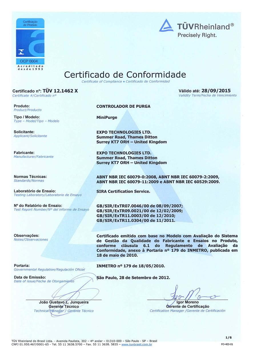
11 4. Drawings Consult the appropriate drawings according to the selected system. SYSTEM *ZLC /bp/is /bp/po /pm/is /pm/po /nm/is /ss/is /ss/po XBR-8TD0-011 XBR-7TD0-030 XBR-8TD0-009 XBR-7TD0-029 XBR-7TD0-031 XBR-8TD0-013 XBR-7TD0-028 (1 & 2) XBR-7TD0-032 EP XSD-RTD0-004 (1 & 2) 5. Certificates System Approval Authority Certificate Number MiniPurge IECEx SIR X Sira 01ATEX 1295X INMETRO/TUV TÜV X FM 1X8A4.AE UL E AGE-SW0Z-017 EXPO11ATEX1200X SC020 ML447 v17 26-Nov-14
12
13
14
15
16 ON PRESSURE FLOW SENSORS SCALE DRAWING No. SHEET No. OF 3rd ANGLE PROJECTION DIMENSIONS IN mm DO NOT SCALE UNSPECIFIED NO DEC PLACE ±0.5 TOLERANCES 1 DEC PLACE ±0.2 2 DEC PLACE ±0.1 FLATNESS TO BE LESS THAN 0.4mm OVER ANY 100mm LENGTH The contents of this drawing / document are Copyright Expo Technologies Limited. They are to be treated as confidential and are returnable upon request. They are not to be copied or communicated in part or in whole without written consent from Expo Technologies Limited, neither are they to be used in any way against our interests. Ex na-ni OR I.S. ALARM SWITCH CONNECTED TO ALARM/ PRESSURIZED SIGNAL OUTPUT (IS OPTION ONLY) 103 [4.1"] 87 [3.4"] ALARM/PRESSURIZED INDICATOR PURGING INDICATOR 212 [8.3"] 180 [7.1"] PURGE AIR INLET 1/2" NPT(F) 165 [6.5"] LEAKAGE COMPENSATION VALVE 58 [2.3"] 36 [1.4"] 182 [7.2"] 208 [8.2"] 59 [2.3"] 96 [3.8"] 31 [1.2"] OFF SYSTEM BREATHER - DO NOT OBSTRUCT 16.5 [0.6"] 37 [1.5"] 35 [1.4"] 167 [6.6"] ALARM/ PRESSURIZED SIGNAL OUTPUT AT SUPPLY PRESSURE 1/8"NPT(F) ENCLOSURE PRESSURE 1/8" NPT(F) PURGE OUTLET 1/2" NPT(F) 4 HOLES Ø5 FOR REAR MOUNTING FLOW SENSING 1/8" NPT(F) PURGE CONTROL VALVE INTERNAL VIEW IS AND PO OPTIONS NOTES: MINI-Z-PURGE/ MINI-Y-PURGE MUST BE MOUNTED IN ONE OF THE TWO ATTITUDES SHOWN. TOP / REAR MOUNT. APPROX WEIGHT: 3Kg (6.6 POUNDS). EACH SYSTEM IS SUPPLIED WITH TWO ORIFICE RESTRICT0RS TO SUIT REQUIRED FLOW RATES. IS OPTION SHOWN IN BROKEN LINE ( ). 5 OFF M4 MOUNTING HOLES SCREWS & SEALOC WASHERS SUPPLIED = = 60 [2.4"] = 110 [4.3"] = GASKET (NOT SHOWN) APPROX 2mm THICK FITTED TO THIS SURFACE ISSUE: MOD. No: DATE: APPROVED: DRAWING STATUS: MATERIAL FINISH Expo Technologies Limited TITLE JOB No: CUSTOMER: SURREY KT7 0RH UNITED KINGDOM
17
18 OFF 150 [5.91"] 90 [3.54"] ON SCALE DRAWING No. 155 [6.10"] CERTIFICATION LABEL PURGE CONTROL VALVE I.S. AND PO OPTIONS: HOLE Ø21 FITTED WITH BLIND GROMMET. FOR USE ON I.S. OPTION AS ALTERNATIVE CABLE ENTRY. SHEET No. OF 3rd ANGLE PROJECTION DIMENSIONS IN mm DO NOT SCALE UNSPECIFIED NO DEC PLACE ±0.5 TOLERANCES 1 DEC PLACE ±0.2 2 DEC PLACE ±0.1 FLATNESS TO BE LESS THAN 0.4mm OVER ANY 100mm LENGTH The contents of this drawing / document are Copyright Expo Technologies Limited. They are to be treated as confidential and are returnable upon request. They are not to be copied or communicated in part or in whole without written consent from Expo Technologies Limited, neither are they to be used in any way against our interests. 240 [9.45"] 180 [7.09"] 65 [2.56"] ALARM/PRESSURIZED SIGNAL OUTPUT AT SUPPLY PRESSURE 1/8"NPT(F) INDICATOR "ALARM/ PRESSURIZED" INDICATOR "PURGING" PURGE INLET 1/2" NPT (F) 45 [1.77"] (PO OPTION ONLY) FLOW SWITCH CONNECTION 1/8"NPT(F) PRESSURE SENSOR 1/8"NPT(F) MOUNTING HOLES TAPPED M6 x 10 DP 41 [1.61"] [3.16"] 75 [2.95"] 44 [1.73"] 62 [2.44"] SIDE VIEW - PO OPTION HOLE - NOT USED - FITTED WITH BLIND GROMMET. SIDE VIEW - IS OPTION PURGE OUTLET 1/2" NPT (F) 55 [2.17"] 35 [1.38"] 96 [3.78"] I.S. OPTION ONLY: HOLE Ø21 FOR CABLE ENTRY 120 [4.72"] = 193 [7.60"] = 65 [2.56"] ISSUE: MOD. No: DATE: APPROVED: DRAWING STATUS: MATERIAL FINISH Expo Technologies Limited TITLE JOB No: CUSTOMER: SURREY KT7 0RH UNITED KINGDOM
19 ALARM SWITCH AS INDICATED. ALL OTHER COMPONENTS SAME AS PO OPTION. SCALE DRAWING No. SHEET No. OF 3rd ANGLE PROJECTION DIMENSIONS IN mm DO NOT SCALE UNSPECIFIED NO DEC PLACE ±0.5 TOLERANCES 1 DEC PLACE ±0.2 2 DEC PLACE ±0.1 FLATNESS TO BE LESS THAN 0.4mm OVER ANY 100mm LENGTH The contents of this drawing / document are Copyright Expo Technologies Limited. They are to be treated as confidential and are returnable upon request. They are not to be copied or communicated in part or in whole without written consent from Expo Technologies Limited, neither are they to be used in any way against our interests. LEAKAGE COMPENSATION VALVE ENCLOSURE PRESSURE TEST POINT (PLUG 4mm) I.S. OPTION ONLY: Ex na-ni OR I.S. ALARM SWITCH SENSOR, FLOW SENSOR, MINIMUM PRESSURE PO OPTION: VIEW WITH DOOR REMOVED IS OPTION: VIEW WITH DOOR REMOVED ISSUE: MOD. No: DATE: APPROVED: DRAWING STATUS: MATERIAL FINISH Expo Technologies Limited TITLE JOB No: CUSTOMER: SURREY KT7 0RH UNITED KINGDOM
20

21 3rd ANGLE PROJECTION DIMENSIONS IN mm DO NOT SCALE The contents of this drawing / document and are returnable upon request. They from Expo Technologies Limited, neither are are are Copyright Expo not to be copied or they to be used in Technologies Limited. communicated in part any way against our They are or in whole interests. to be treated as without written confidential consent Fig 1a Single channel interface circuit e.g. "Y" or "Z" Pressurization Alarm circuit Fig 1b Multi-channel interface circuit e.g. "X" pressurization Alarm & Power Control Hazardous Location Hazardous Location Class I or II, Div 1 or 2 Class I or II, Div 1 or 2 Groups A, B, C, D, E, F and G Groups A, B, C, D, E, F and G Non-Hazardous Location M inipurge: Option Code /IS MiniPurge: Option Code /I S (or suitably protected apparatus) I.S. Interface Unit Power supply + Vmax Imax Ci = 0 = 30V = 100mA Li = 0 Non-Hazardous Location (or I.S. suitably protected apparatus) Interface Unit Power supply Outputs e.g. to relays or power contactors. or power contactors. Simple apparatus device Vmax = 30V Imax = 100mA Ci = 0 Li = 0 Outputs e.g. to relays PCB Pt# S108/* (* = configuration) Simple Apparatus Connection for M Manual Override Switch (dry contact) Vmax = 0V, Imax = 0A, Ci = 0, Li = 0 Notes for both Fig 1a and Fig 1b 1 Electrical equipment connected to associated apparatus should not use or generate more than 250 volts 2 Installation shall be in accordance with the manufacturer's instructions and the National Electrical Code (ANSI/NFPA 70) 3 For guidance on Installation see ANSI/ISA RP12.6, (Installation of IS Instrument Systems in Class I Hazardous Locations) 4 Voc or Vt of associated apparatus is less than Vmax Isc or It of associated apparatus is less than Imax Ci plus capacitance of interconnecting cabling is less than Ca of the associated apparatus Li plus inductance of interconnecting cabling is less than La of the associated apparatus 5 "Simple Apparatus" is a device that will not generate or store more than 1.2V, 0.1A, 25mW or 20uJ 6 For Gas Groups A, B permitted Imax for I.S., for V peak = 30V is 101 ma Alternatively: For Gas Group A, B with Vpeak = 19.2V Imax for I.S. is 350mA. REV. MOD NUMBE R APPROVED DAT E APPROVE D Expo Technologies Limited D RAWN DATE: 13/07/2007 SURREY KT7 0RH SCALE REV : THIS IS A CERTIFICATION UNITED KINGDOM NTS DRAWING STATUS: Certified APP'D CHK' D DR'W N A MO A M O AM O T ITLE DRAWING No. JOB No: CUSTOMER: EP SHEET No. O F 06 DOCUMENT /7/200 7 ML C /11/201 0 AM O /07/201 1 AM O ANY UNAUTHORISED CHANGE INVALIDATES APPROVAL. MINIPURGE OPTION 'IS' 1
22 WIDTH X 62 [2.44"] 88 [3.46"] HEIGHT Y 133 [5.24"] 170 [6.69"] 110 [4.33"] 185 [7.28"] DEPTH Z 28 [1.10"] 33 [1.30"] 37 [1.46"] SCALE DRAWING No. SHEET No. OF 3rd ANGLE PROJECTION DIMENSIONS IN mm DO NOT SCALE UNSPECIFIED NO DEC PLACE ±0.5 TOLERANCES 1 DEC PLACE ±0.2 2 DEC PLACE ±0.1 FLATNESS TO BE LESS THAN 0.4mm OVER ANY 100mm LENGTH The contents of this drawing / document are Copyright Expo Technologies Limited. They are to be treated as confidential and are returnable upon request. They are not to be copied or communicated in part or in whole without written consent from Expo Technologies Limited, neither are they to be used in any way against our interests. Z GASKET 5 [0.20"] BEFORE COMPRESSION X 25 [1.0"] MINIPURGE SIZE 1 RLV25 MIN 25 [1.0"] Y SIZE 2 RLV36 SIZE 3 RLV52 ISSUE: MOD. No: DATE: APPROVED: DRAWING STATUS: MATERIAL FINISH Expo Technologies Limited TITLE JOB No: CUSTOMER: SURREY KT7 0RH UNITED KINGDOM
23 DETAIL 'A' DETAIL 'B' DETAIL 'C' RLV25 CUTOUT RLV36 CUTOUT RLV52 CUTOUT 4 HOLES Ø5.5 [7/32"] SCALE DRAWING No. RLV OUTLINE SHEET No. OF 3rd ANGLE PROJECTION DIMENSIONS IN mm DO NOT SCALE UNSPECIFIED NO DEC PLACE ±0.5 TOLERANCES 1 DEC PLACE ±0.2 2 DEC PLACE ±0.1 FLATNESS TO BE LESS THAN 0.4mm OVER ANY 100mm LENGTH The contents of this drawing / document are Copyright Expo Technologies Limited. They are to be treated as confidential and are returnable upon request. They are not to be copied or communicated in part or in whole without written consent from Expo Technologies Limited, neither are they to be used in any way against our interests. HOLE Ø [1 1/2"] HOLE Ø [2" ] HOLE Ø [1" ] RLV OUTLINE RLV OUTLINE 133 [5.24"] 46 [1.81"] = = 44 [1.73"] 170 [6.69"] 56 [2.20"] = 64 [2.52"] = 185 [7.28"] 65 [2.56"] = 76 [3.00"] = = = 44 [1.73"] = 62 [2.44"] = = 64 [2.52"] = = 88 [3.46"] = = 76 [3.00"] = = 109 [4.29"] = 4 HOLES Ø5.5 [7/32"] 4 HOLES Ø5.5 [7/32"] ISSUE: MOD. No: DATE: APPROVED: DRAWING STATUS: MATERIAL FINISH Expo Technologies Limited TITLE JOB No: CUSTOMER: SURREY KT7 0RH UNITED KINGDOM


24


25


26
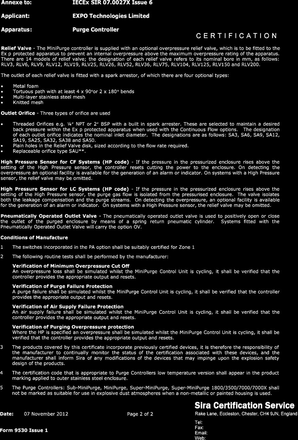
27 CERTIFICATION 1 EC TYPE-EXAMINATION CERTIFICATE 2 Equipment intended for use in Potentially Explosive Atmospheres Directive 94/9/EC 3 Certificate Number: Sira 01ATEX1295X Issue: 8 4 Equipment: Purge Controllers: Sub-MiniPurge, MiniPurge, Super-MiniPurge, Super-MiniPurge 1800/3500/7000/7000X 5 Applicant: EXPO Technologies Limited 6 Address: Unit 2, The Summit, Hanworth Road, Sunbury on Thames, Surrey TW16 5DB UK 7 This equipment and any acceptable variation thereto is specified in the schedule to this certificate and the documents therein referred to. 8 Sira Certification Service, notified body number 0518 in accordance with Article 9 of Directive 94/9/EC of 23 March 1994, certifies that this equipment has been found to comply with the Essential Health and Safety Requirements relating to the design and construction of equipment intended for use in potentially explosive atmospheres given in Annex II to the Directive. The examination and test results are recorded in the confidential reports listed in Section Compliance with the Essential Health and Safety Requirements, with the exception of those listed in the schedule to this certificate, has been assured by compliance with the following documents: IEC :2011 EN :2007 EN : If the sign X is placed after the certificate number, it indicates that the equipment is subject to special conditions for safe use specified in the schedule to this certificate. 11 This EC type-examination certificate relates only to the design and construction of the specified equipment. If applicable, further requirements of this Directive apply to the manufacture and supply of this equipment. 12 The marking of the equipment shall include the following: Standard versions Low temperature versions II 2(2) GD II 2(2) GD Ex [px] IIC T6 Gb Ex [px] dem IIC T3 or T4 Gb Ex [py] IIC T6 Gb Ex [p] IIIC T200 C or T135 C Db Ex [p] IIIC T85 C Db (Ta 50 C to +55 C) (Ta 20 C to +55 C) II 2(3) GD Ex [pz Gc ] IIC T6 Gb Ex [p Dc] IIIC T85 C Db (Ta 20 C to +55 C) Standard /ET versions Low temperature /ET versions II 2(2) GD II 2(2) GD Ex [px] ia IIC T6 Gb Ex [px] dem ia IIC T3 or T4 Gb Ex [p] ia IIIC T95 C Db Ex [p] ia IIIC T200 C or T135 C Db (Ta 20 o C to +55 o C) (Ta 50 C to +55 C) Project Number C Ellaby Deputy Certification Manager This certificate and its schedules may only be reproduced in its entirety and without change. Form 9400 Issue 1 Page 1 of 7 Sira Certification Service Rake Lane, Eccleston, Chester, CH4 9JN, England Tel: +44 (0) Fax: +44 (0) info@siracertification.com Web: CERTIFICATION SCHEDULE EC TYPE-EXAMINATION CERTIFICATE Sira 01ATEX1295X Issue 8 13 DESCRIPTION OF EQUIPMENT The Purge Controllers are pneumatically operated devices, which are intended to provide a given flow rate of purging gas for a predetermined time to unspecified Ex p protected electrical equipment. The MiniPurge Control Units provide one of the following four methods of purge operation. LC-Leakage compensation only after initial high purge CF-Continuous flow (same flow rate during and after purging) CF2-Two flow CF system with initial high purge rate only at one orifice CFHP-Continuous (lower) flow after initial high purge The MiniPurge control unit may be supplied within a heated enclosure to permit the use of the system within an ambient temperature down to 50 o C. The MiniPurge option pd is for use in combustible dust Relief Valve - The MiniPurge controller is supplied with an optional overpressure relief valve, which is to be fitted to the Ex p protected apparatus to prevent an internal overpressure above the maximum overpressure rating of the apparatus. There are 14 models of relief valve; the designation of each relief valve refers to its nominal bore in mm, as follows: RLV3, RLV6, RLV9, RLV12, RLV19, RLV25, RLV26, RLV52, RLV36, RLV75, RLV104, RLV125, RLV150 and RLV200. The outlet of each relief valve is fitted with a spark arrestor, of which there are four optional types: Metal foam Multi-layer stainless steel mesh Tortuous path with at least 4 x 90 or 2 x 180 bends Knitted mesh Outlet Orifice - Three types of orifice are used: Threaded Orifices e.g. ¼ NPT or 2 BSP with a built in spark arrester. These are selected to maintain a desired back pressure within the Ex p protected apparatus when used with the Continuous Flow options. The designation of each outlet orifice indicates the nominal inlet diameter. The designations are as follows: SA3, SA6, SA9, SA12, SA19, SA25, SA32, SA38 and SA50. Plain holes in the Relief Valve disk, sized according to the flow rate required. Replaceable orifice type SAU**. High Pressure Sensor for CF Systems (HP code) - If the pressure in the pressurized enclosure rises above the setting of the High Pressure sensor, the controller resets cutting the power to the enclosure. On detecting the overpressure an optional facility is available for the generation of an alarm or indicator. On systems with a High Pressure sensor, the relief valve may be omitted. High Pressure Sensor for LC Systems (HP code) - If the pressure in the pressurized enclosure rises above the setting of the High Pressure sensor, the purge gas flow is isolated from the pressurised enclosure. The valve isolates both the leakage compensation and the purge streams. On detecting the overpressure, an optional facility is available for the generation of an alarm or indicator. On systems with a High Pressure sensor, the relief valve may be omitted. Pneumatically Operated Outlet Valve - The pneumatically operated outlet valve is used to positively open or close the outlet of the purged enclosure by means of a spring return pneumatic cylinder. Systems fitted with the Pneumatically Operated Outlet Valve will carry the option OV. This certificate and its schedules may only be reproduced in its entirety and without change. Form 9400 Issue1 Page 2 of 7 Sira Certification Service Rake Lane, Eccleston, Chester, CH4 9JN, England Tel: +44 (0) Fax: +44 (0) info@siracertification.com Web:
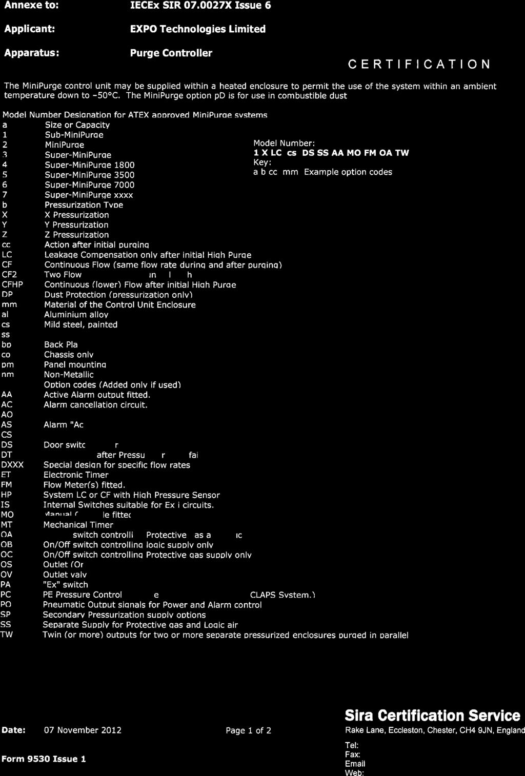
28 CERTIFICATION SCHEDULE EC TYPE-EXAMINATION CERTIFICATE Sira 01ATEX1295X Issue 8 Model Number Designation for ATEX approved MiniPurge systems a Size or Capacity 1 Sub-MiniPurge 2 MiniPurge 3 Super-MiniPurge This certificate and its schedules may only be reproduced in its entirety and without change. Form 9400 Issue1 4 Super-MiniPurge Super-MiniPurge Super-MiniPurge Super-MiniPurge xxxx b Pressurization Type X X Pressurization Y Y Pressurization Z Z Pressurization cc Action after initial purging LC Leakage Compensation only after initial High Purge CF Continuous Flow (same flow rate during and after purging) CF2 Two Flow CF system with initial High Purge rate but only one orifice CFHP Continuous (lower) Flow after initial High Purge DP Dust Protection (pressurization only) mm Material of the Control Unit Enclosure al Aluminium alloy cs Mild steel, painted ss Stainless steel bp Back Plate only co Chassis only pm Panel mounting nm Non-Metallic Option codes (Added only if used) Page 3 of 7 Model Number: 1 X LC cs DS SS AA MO FM OA TW Key: a b cc mm Example option codes AA Active Alarm output fitted. AC Alarm cancellation circuit. AO "Alarm Only" Action on Pressure or Flow Failure. AS Alarm "Action on Pressure or Flow failure", Selector valve. CS Containment System Monitor. DS Door switch Power Interlock fitted. DT Delayed Trip after Pressure or Flow failure. DXXX Special design for specific flow rates ET Electronic Timer FM Flow Meter(s) fitted. HP System LC or CF with High Pressure Sensor IS Internal Switches suitable for Ex i circuits. MO Manual Override fitted. MT Mechanical Timer. OA On/Off switch controlling Protective gas and logic supply. OB On/Off switch controlling logic supply only. OC On/Off switch controlling Protective gas supply only. OS Outlet (Orifice) Selector valve. OV Outlet valve, pneumatically operated. PA "Ex" switch(es) built-in, with/without "Ex" junction box. PC PE Pressure Control Leakage Compensation Valve (CLAPS System.) PO Pneumatic Output signals for Power and Alarm control. SP Secondary Pressurization supply options. SS Separate Supply for Protective gas and Logic air. TW Twin (or more) outputs for two or more separate pressurized enclosures purged in parallel Sira Certification Service Rake Lane, Eccleston, Chester, CH4 9JN, England Tel: +44 (0) Fax: +44 (0) info@siracertification.com Web: CERTIFICATION SCHEDULE EC TYPE-EXAMINATION CERTIFICATE Sira 01ATEX1295X Issue 8 Variation 1 This variation introduced the following changes: i. The purge controller to be fitted inside an additional, heated, stainless steel enclosure that allows it to be used down to -50 o C. The heater (500 W maximum) is manufactured by Intertec-Hess GmbH and coded Ex d m IIC T3 (max) under PTB 02ATEX1041X. If the outer enclosure is reduced in size the power of the heater may be reduced in proportion to the reduction in surface area. Other alternative heaters may be used as a replacement if they are suitably certified, carry the same or greater ambient temperature range, occupy the same or smaller physical space, have the same certification code and have the same or more restrictive Temperature Class. The enclosure is made from 1.5mm or 2.5 mm thick stainless or mild steel painted and the lid is made from 1.5 mm thick stainless steel, lined with 38 mm thick insulation, or other materials with equivalent insulating properties. The purge inlet, purge outlet and pressure sensing lines are similarly insulated. The door may optionally be hinged with quick release catches, these will be fitted with a padlock. An enclosure breather tube is fitted to help prevent condensation. A plastic clear viewing window may optionally be fitted to the door. RTDs are fitted to the air inlet pipe-work and inside the purge controller enclosure. An Ex e terminal box is provided within the main enclosure for connection of the heater leads. This polyester box is manufactured by Bartec and coded Ex e II T6 under BAS 98ATEX3008X. Other alternative ATEX terminal boxes may be used as a replacement if they are suitably certified, carry the same or greater ambient temperature range, occupy the same or smaller physical space, have the same certification code and have the same Temperature Class. Any suitably ATEX, Category 2 approved cable gland may be used, if it can be used with the ambient temperature range. ii. A change of the Applicant s name on the certificate and the substitution of the new name for the old name on the approved label affixed to the purge controllers: Old Name: New name: Expo Telektron Safety System Limited Expo Technologies Limited Variation 2 This variation introduced the following change: i. To permit the pressurisation of enclosures for the exclusion of combustible dusts in accordance with IEC :2001 and modification of the marking to include one of the following: [Ex pd] II T200 C 21 (Ta = -20 C to +55 C) - (used with the low temperature versions) [Ex pd] II T85 C 21 (Ta = -20 C to +55 C) - (used with the standard temperature versions) The ATEX coding is modified to: II 2(2) G D This certificate and its schedules may only be reproduced in its entirety and without change. Form 9400 Issue1 Page 4 of 7 Sira Certification Service Rake Lane, Eccleston, Chester, CH4 9JN, England Tel: +44 (0) Fax: +44 (0) info@siracertification.com Web:
29 CERTIFICATION SCHEDULE EC TYPE-EXAMINATION CERTIFICATE Sira 01ATEX1295X Issue 8 Variation 3 This variation introduced the following changes: i. Following appropriate re-assessment to demonstrate compliance with the requirements of the EN series of standards, the documents originally listed in section 9, EN 50014:1997 (amendments A1 to A2) and EN 50016:1995, were replaced by EN :2006, EN :2004, EN :2006 and EN :2006, the markings in section 12 were updated accordingly. ii. The removal of special conditions for safe use that were not specifically associated with the equipment covered by this certificate. Variation 4 - This variation introduced the following changes: i. To permit the inclusion of the following coding for the Low Temperature MiniPurge Enclosure: Ex [p] dem IIC T4 Ex pd II 21 T135 C (Ta 50 o C to +55 o C) Variation 5 - This variation introduced the following changes: i. The introduction of the /ET version, an alternative to the pneumatic or mechanical timer system, this incorporates an Electronic Timer Module ETM-IS**-*** in the Mini Purge, the certification includes ia marking when the ETM is fitted. ii. The dust marking was changed to be consistent with the marking for gases and vapours. iii. The introduction of a high pressure sensor for the LC option. Variation 6 - This variation introduced the following changes: i. Following appropriate re-assessment to demonstrate compliance with the requirements of the latest EN series of standards, the documents previously listed in section 9, EN : 2006 and EN : 2004 were replaced by those currently listed (EN : 2006 was removed as this is incorporated into the current version of ), the markings in section 12 were updated accordingly and a new condition of certification was added. Variation 7 - This variation introduced the following changes: i. The recognition of the Applicant s address change from Summer Road, Thames Ditton, Surrey KT7 0RH to Unit 2, The Summit, Hanworth Road, Sunbury on Thames, Surrey TW16 5DB. 14 DESCRIPTIVE DOCUMENTS 14.1 Drawings Refer to Certificate Annexe Associated Sira Reports and Certificate History Issue Date Report no. Comment 0 3 July 2002 R53A7169A The release of prime certificate March 2004 R53V11342A The introduction of Variation September 2004 R51A11080A The introduction of Variation September 2006 R51A15629A The re-issue of Variation 2 to include the changes described in report number R51A15629A. This certificate and its schedules may only be reproduced in its entirety and without change. Form 9400 Issue1 Page 5 of 7 Sira Certification Service Rake Lane, Eccleston, Chester, CH4 9JN, England Tel: +44 (0) Fax: +44 (0) info@siracertification.com Web: CERTIFICATION SCHEDULE EC TYPE-EXAMINATION CERTIFICATE Sira 01ATEX1295X Issue 8 Issue Date Report no. Comment 4 7 June 2007 R51L15966B This Issue covers the following changes: All previously issued certification was rationalised into a single certificate, Issue 4, Issues 0 to 3 referenced above are only intended to reflect the history of the previous certification and have not been issued as documents in this format. The introduction of Variation February 2009 R51L19695A The introduction of Variation December 2010 R23665A/00 This Issue covers the following changes: This certificate history was modified to recognise that that Variation 2 was re-issued, subsequent Variations have therefore been re-numbered. The introduction of Variation December 2011 R25983A/00 The introduction of Variation October 2012 R29097A/00 The introduction of Variation SPECIAL CONDITIONS FOR SAFE USE (denoted by X after the certificate number) 15.1 When using the AO, AS and DT options, the recommendations for the additional requirements of Ex p apparatus contained within EN shall be applied The installer/user shall ensure that the MiniPurge Control Unit is installed in accordance with the equipment certificate that covers the combination of the pressurised enclosure(s) and MiniPurge Control Unit The values of the safety parameters shall be set in accordance with the equipment certificate that covers the combination of the pressurised enclosure(s) and MiniPurge Control Unit This MiniPurge Control Unit shall be incorporated into equipment and the appropriate Conformity Assessment Procedures applied to the combination as defined by Directive 94/9/EC. This certificate does not cover the combination The purge controller, low temperature version, shall be protected by a safety related system that ensures that it cannot be energised if the temperature of the air inlet or purge controller falls below - 20 o C. This system shall utilise the RTDs that are fitted to the purge controller to provide the appropriate level of system integrity, i.e. a level of operational safety of Cat 3 according to EN for ATEX Category 2 (Zone 1) applications; note that these RTDs have not been assessed as a safety related device in accordance with EHSR 1.5 of Directive 94/9/EC. 16 ESSENTIAL HEALTH AND SAFETY REQUIREMENTS (EHSRs) The relevant EHSRs that are not addressed by the standards listed in this certificate have been identified and individually assessed reports listed in Section CONDITIONS OF CERTIFICATION 17.1 The use of this certificate is subject to the Regulations Applicable to Holders of Sira Certificates Holders of Type Examination Certificates are required to comply with the production control requirements defined in Article 8 of directive 94/9/EC. This certificate and its schedules may only be reproduced in its entirety and without change. Form 9400 Issue1 Page 6 of 7 Sira Certification Service Rake Lane, Eccleston, Chester, CH4 9JN, England Tel: +44 (0) Fax: +44 (0) info@siracertification.com Web:

30 CERTIFICATION SCHEDULE EC TYPE-EXAMINATION CERTIFICATE Sira 01ATEX1295X Issue The switches incorporated in the PA option shall be suitably certified for Category The following routine tests shall be performed by the manufacturer: Verification of Minimum Overpressure Cut Off An overpressure loss shall be simulated whilst the MiniPurge Control Unit is cycling, it shall be verified that the controller provides the appropriate output and resets. Verification of Purge Failure Protection A purge failure shall be simulated whilst the MiniPurge Control Unit is cycling, it shall be verified that the controller provides the appropriate output and resets. Verification of Air Supply Failure Protection An air supply failure shall be simulated whilst the MiniPurge Control Unit is cycling, it shall be verified that the controller provides the appropriate output and resets. Verification of Purging Overpressure protection Where the HP is specified an overpressure shall be simulated whilst the MiniPurge Control Unit is cycling, it shall be verified that the controller provides the appropriate output and resets The products covered by this certificate incorporate previously certified devices, it is therefore the responsibility of the manufacturer to continually monitor the status of the certification associated with these devices, and the manufacturer shall inform Sira of any modifications of the devices that may impinge upon the explosion safety design of the products The certification code that is appropriate to Purge Controllers low temperature version shall appear in the product marking applied to outer stainless steel enclosure The Purge Controllers: Sub-MiniPurge, MiniPurge, Super-MiniPurge, Super-MiniPurge 1800/3500/7000/7000X shall not be marked as suitable for use in explosive dust atmospheres when a non-metallic or painted housing is used. This certificate and its schedules may only be reproduced in its entirety and without change. Form 9400 Issue1 Page 7 of 7 Sira Certification Service Rake Lane, Eccleston, Chester, CH4 9JN, England Tel: +44 (0) Fax: +44 (0) info@siracertification.com Web: Certificate Annexe Certificate Number: Sira 01ATEX1295X Equipment: Purge Controllers Sub-MiniPurge, MiniPurge, Super-MiniPurge, Super-MiniPurge 1800/3500/7000/7000X CERTIFICATION Applicant: EXPO Technologies Limited Issue 0 (The drawings associated with this issue were replaced by those listed in Issue 4) Number Sheet Rev. Date Description SD to Jul 02 MiniPurge ATEX Certification Labelling SD to May 01 MiniPurge ATEX Certification Type Numbering Scheme EP/ of Sep 00 MiniPurge, Continuous Flow with /HP Sensor Schematic diagram EP of Sep 00 RLV, outlet orifice EP of Sep 00 Outlet Valve Control Circuit Diagram Issue 1 (The drawings associated with this issue were replaced by those listed in Issue 4) Number Sheet Rev. Date Description SD of March 04 Low Temperature Housing - General Arrangement Issue 2 (The drawings associated with this issue were replaced by those listed in Issue 4) Number Sheet Rev. Date Description SD7281* 1 to Dec 03 Certification label SD of Dec 03 Low temperature housing wiring certification drawing. * Modified by Sira 30 September 2004 Issue 3 (The drawings associated with this issue were replaced by those listed in Issue 4) Number Sheet Rev. Date Description SD to Aug 06 Certification label Issue 4 Number Sheet Rev. Date Description EP of Mar 07 Minipurge Control Unit General Assembly EP of Jul 07 Schematic - Type x Leakage Compensation EP of Mar 07 Sequence Diagram - Type x Leakage Compensation EP of Mar 07 Schematic - Type x Continuous Flow EP of Mar 07 Schematic Separate Supply and Mechanical Timer EP of Mar 07 Schematic Delay Before Trip and On/Off EP of Mar 07 Schematic Twin Output and Manual Override EP of Mar 07 Schematic Pressure Control Leakage Compensation EP of Mar 07 Internal IS Switches EP of Mar 07 Schematic Containment System and Secondary pressurisation EP of Mar 07 Schematic Continuous Flow with 2 Flow Rates EP of Mar 07 Schematic Continuous Flow with High Pressure EP of Mar 07 Schematic Outlet Valve Control SD of Mar 07 Schematic Dust Protection SD of Mar 07 Spark Arrestor SD of Apr 07 Differential Flow Monitor SD of Mar 07 Continuous Flow Outlet Orifice SD of Mar 07 Wiring Diagram Low temperature SD of Apr 07 Outlet Orifice Closing Device SD of Mar 07 Low Temperature Housing SD to Feb 07 Certification Label Details SD to Feb 07 MiniPurge Data Sheet This certificate and its schedules may only be reproduced in its entirety and without change. Form 9400 Issue 1 Page 1 of 2 Sira Certification Service Rake Lane, Eccleston, Chester, CH4 9JN, England Tel: +44 (0) Fax: +44 (0) info@siracertification.com Web:
31 Certificate Annexe Certificate Number: Sira 01ATEX1295X Equipment: Purge Controllers Sub-MiniPurge, MiniPurge, Super-MiniPurge, Super-MiniPurge 1800/3500/7000/7000X CERTIFICATION Applicant: EXPO Technologies Limited Number Sheet Rev. Date Description SD to Feb 07 Fault Evaluation EP of Mar 07 Outlet Valve Circuit N/O EP of Mar 07 Outlet Control Valve N/C SD of Jul 07 Schematic Type Z or Y leakage compensation SD of Mar 07 Schematic Type Z or Y Continuous Flow EP of Mar 07 Sequence Diagram Type X Continuous Flow EP of Mar 07 Schematic Alarm only and Alarm Action Selector EP of Mar 07 Schematic Door Switch Active Alarm and Alarm Cancel SD to Jul 07 RLV Configurations SD of Jul 07 Alternative Z&Y LC System SD of Jul 07 Alternative Z&Y LC System Issue 5 Number Sheets Rev. Date (Sira stamp) Description SD to Feb 09 Minipurge ATEX/IECEx Certification Label SD of Feb 09 Minipurge Low temperature Housing Issue 6 Number Sheets Rev. Date (Sira stamp) Description SD to Dec 10 Minipurge ATEX/IECEx Certification Label SD to Dec 10 MiniPurge Data Sheet SD of Dec 10 MiniPurge electronic timer SD of Dec 10 MiniPurge HP sensor Issue 7 Number Sheets Rev. Date (Sira stamp) Description SD of Nov 11 Minipurge Low Temperature Housing SD & Nov 11 Minipurge Data Sheets SD to Nov 11 Minipurge ATEX/IECEx Certification Label SD of Nov 11 Minipurge Dust Protection Schematic Issue 8 Number Sheets Rev. Date (Sira stamp) Title SD to Oct 12 Minipurge Certification Label This certificate and its schedules may only be reproduced in its entirety and without change. Form 9400 Issue 1 Page 2 of 2 Sira Certification Service Rake Lane, Eccleston, Chester, CH4 9JN, England Tel: +44 (0) Fax: +44 (0) info@siracertification.com Web:
32

33

34
35
36
37 2012 UL LLC 1/1 rizing 11/7/12 Controls and Accessories for Use in Hazardous Locati zing 11/7/12 Controls and Accessories for Use in Hazardous Locations RFPW7.E Purging and Pressurizing Controls and Accessories for Use in Hazardous Locations Certified for Canada Page Bottom Purging and Pressurizing Controls and Accessories for Use in Hazardous Locations Certified for Canada RFPW.E Purging and Pressurizing Controls and Accessories for Use in Hazardous Locations Page Bottom Purging and Pressurizing Controls and Accessories for Use in Hazardous Locations See General Inform ation for Purging and Pressurizing Controls and Accessories for Use in Hazardous Locations See General Inform ation for Purging and Pressurizing Controls and Accessories for Use in Hazardous Locations Certified for Canada EXPO TECHNOLOGIES LIMITED E UNIT 2 THE SUMMIT HANWORTH ROAD SUNBURY ON THAMES, SURREY TW16 5DB UNITED KINGDOM Purge control units, Type X for use in hazardous (classified) locations, Model** 1, 2, 3, 4, 5, 6 or 7 followed by X, followed by CF, CFHP or LC, followed by BP, CS, PM, SS, may be followed by AO, DS, DT, IS, MO, PO, SS. Type Y for use in hazardous (classified) locations, Model** 1, 2, 3, 4, 5, 6 or 7 followed by Y, followed by CF, CFHP or LC, followed by BP, CS, NM, PM, SS, may be followed by AO, DS, DT, IS, MO, NO, PO, SS. Type Z for use in hazardous (classified) locations, Models** 1, 2, 3, 4, 5, 6 followed by Z, followed by CF, CFHP or LC, followed by BP, CS, PM, SS, may be followed by AO, DS, DT, IS, MO, NO, PO, SS. Purge control accessory: Vent unit for use in hazardous (classified) locations, Model RLV followed by 25, 36, 52, 75, 104, 125, 150, or 200, followed by CS or SS, may be followed by FS. ** - Internal series identifier, precedes model number, which may contain one or more characters. Last Updated on EXPO TECHNOLOGIES LIMITED E UNIT 2 THE SUMMIT HANWORTH ROAD SUNBURY ON THAMES, SURREY TW16 5DB UNITED KINGDOM Purge control units, Type X for use in hazardous (classified) locations, Model** 1, 2, 3, 4, 5, 6 or 7 followed by X, followed by CF, CFHP or LC, followed by BP, CS, PM, SS, may be followed by AO, DS, DT, IS, MO, PO, SS. Type Y for use in hazardous (classified) locations, Model** 1, 2, 3, 4, 5, 6 or 7 followed by Y, followed by CF, CFHP or LC, followed by BP, CS, NM, PM, SS, may be followed by AO, DS, DT, IS, MO, NO, PO, SS. Type Z for use in hazardous (classified) locations, Models** 1, 2, 3, 4, 5, 6 followed by Z, followed by CF, CFHP or LC, followed by BP, CS, PM, SS, may be followed by AO, DS, DT, IS, MO, NO, PO, SS. Purge control accessory: Vent unit for use in hazardous (classified) locations, Model RLV followed by 25, 36, 52, 75, 104, 125, 150, or 200, followed by CS or SS, may be followed by FS. ** - Internal series identifier, precedes model number, which may contain one or more characters. Last Updated on Questions? Print this page Term s of Use Page Top Questions? Print this page Term s of Use Page Top When the UL Leaf Mark is on the product, or wh en the word "Environm ent" is included in the UL Mark, please search the UL Environm ent database for additional inform ation regarding this product's certification UL LLC The appearance of a company's nam e or product in this database does not in itself assure that products so identified have been m anufactured under UL's Follow-Up Service. Only those products bearing the UL Mark should be considered to be Listed and covered under UL's Follow-Up Service. Always look for the Mark on the product. UL perm its the reproduction of the material contained in the Online Certification Directory subject to the following conditions: 1. The Guide Inform ation, Designs and/or Listings (files) must be presented in their entirety and in a non-misleading manner, without any manipulation of the data (or drawings). 2. The statem ent "Reprinted from the Online Certifications Directory with perm ission from UL" must appear adjacent to the extracted material. In addition, the reprinted material must include a copyright notice in the following form at: " 2012 UL LLC". When the UL Leaf Mark is on the product, or wh en the word "Environm ent" is included in the UL Mark, please search the UL Environm ent database for additional inform ation regarding this product's certification. The appearance of a company's nam e or product in this database does not in itself assure that products so identified have been m anufactured under UL's Follow-Up Service. Only those products bearing the UL Mark should be considered to be Listed and covered under UL's Follow-Up Service. Always look for the Mark on the product. UL perm its the reproduction of the material contained in the Online Certification Directory subject to the following conditions: 1. The Guide Inform ation, Designs and/or Listings (files) must be presented in their entirety and in a non-misleading manner, without any manipulation of the data (or drawings). 2. The statem ent "Reprinted from the Online Certifications Directory with perm ission from UL" must appear adjacent to the extracted material. In addition, the reprinted material must include a copyright notice in the following form at: " 2012 UL LLC". database.ul.com/cgi-bin/xyv/template/lisext/1frame/show page.html?name=rfpw7.e190061&cc 1/1 database.ul.com/cgi-bin/xyv/template/lisext/1frame/show page.html?name=rfpw.e190061&ccn
 This declaration is issued for the electrical apparatus: AGE-SW0Z-017 non- sparking switch (4) Manufacturer: Expo Technologies Ltd Unit 2, The Summit Hanworth Road Sunbury on Thames TW16 5DB (5)")
 This declaration and schedule confirms compliance of each unit with the following standards: EN 60079-0: 2009 EN 60079-18: 2009 General requirements Encapsulation m (7) This apparatus fulfils all")
38 (1) Declaration of Conformity. (2) Expo Technologies Document Number EXPO11ATEX1200X/3. (3) This declaration is issued for the electrical apparatus: AGE-SW0Z-017 non- sparking switch (4) Manufacturer: Expo Technologies Ltd Unit 2, The Summit Hanworth Road Sunbury on Thames TW16 5DB (5) This electrical apparatus and any acceptable variation thereto is specified in the Annex to this certificate and the documents therein referred to. (6) This declaration and schedule confirms compliance of each unit with the following standards: EN : 2009 EN : 2009 General requirements Encapsulation m (7) This apparatus fulfils all the requirements for Group II Category 3 equipment in accordance with European Directive 94/9/EC. (8) The design is documented in Expo Technologies Technical Construction File number (9) The apparatus marking: Ex m IIC T4 Gc II 3 G For and on behalf of Expo Technologies Ltd. Sunbury on Thames, 14th October Sarah Wickson Certification Engineer Page 1 of 2 Expo Technologies Ltd. Registered in England No David Baker Certification Engineer Expo Technologies Ltd Unit 2, The Summit, Hanworth Rd. Sunbury on Thames, Surrey. TW16 5DB T +44 (0) F +44 (0) E info@expoworldwide.com
39 Annex to Declaration of Conformity EXPO11ATEX1200X/3. 10 Description: A pneumatically operated, hermetically sealed switch. The switch is contained in an aluminium alloy 6082 block encapsulated with an epoxy resin potting compound. Ambient temperature range 20 C to + 55 C. 11 Switch data: Maximum Voltage 254Vac rms Maximum Current 0.7A Humidity range 0% to 100% RH at 55 C, condensing. Pneumatic signal: 22 to 100 p.s.i Barg. 12 Special conditions of safe use: The unit shall be grounded using a cable lug and appropriate grounding wire. The conductor shall be secured against loosening or twisting and that contact pressure is permanently secured. The circuit shall be protected by a suitable fuse or similar device. 13 Test Documentation Description Doc. Ref. Rev. General Arrangement AGE-SW0Z Reed switch data sheet Test procedure TP WD 2 Revision History Version Date Comment 0 12-Oct-2011 Initial issue of DoC 1 7-Jun-2012 Maximum voltage modified from 230V to 254Vac rms 2 27-Sep-2013 Manufacturer s address updated 3 14-Oct-2013 Rectification of anomalies in address Page 2 of 2 Expo Technologies Ltd. Registered in England No Expo Technologies Ltd Unit 2, The Summit, Hanworth Rd. Sunbury on Thames, Surrey. TW16 5DB T +44 (0) F +44 (0) E info@expoworldwide.com

40 Manufacturer s Self Evaluation In accordance with NFPA-70 National Electric Code Clause Expo Technologies Ltd Hanworth Road Sunbury on Thames, TW16 5DB UK The non-incendive switch AGE-SW0Z-017 Manufactured by Expo Technologies can be marked for use in Class I division 2 hazardous location. The switch contacts are formed of a reed switch which is a hermetically sealed contact. It is therefore is suitable for use in Class I Division 2 Hazardous Location in accordance with NFPA-70 clause J Hermetically sealed. NEC B 1 Exception 2 Allows for hermetically sealed devices to be used as an alternative to using a listed device. i.e. there is not a requirement for these to be listed. Similarly exception 2 also permits hermetically sealed switch for use as remote alarm. The switch is marked with the voltage and current ration of the hermetically sealed contacts and is marked as V max I max P max Non Incendive Circuit 254V AC 200V DC 1 Amp 70 W For Intinsically safe circuits or the switch contact is simple apparatus as described in NEC504.2 and used with control drawing EP Similarly for non incendive circuits the switch is simple apparatus ( though also hermetically sealed.). Therefore the switch AGE-SW0Z-017 can be used as simple apparatus either in an intrinsically safe circuit or in a non incendive circuit, or it can be used as a hermetically sealed contact in a Class I Division2 Location within the ratings shown. Signed Date 7 June 2012 Managing Director S:\Files\QA\CERTS\C-OF-C\SC020 V3 Non Incendive switch.doc Confidential Assessment file reference SC020 V3 10 Jun 13


41 EC-Declaration of Conformity With European Directives This is to declare that Purge Controllers Type MiniPurge are manufactured in conformity with the following European Directives and standards: Expo Technologies Ltd Unit 2, The Summit, Hanworth Road Sunbury on Thames TW16 5DB, UK Electromagnetic Compatibility Directive 2004/108/EG MiniPurge Systems with a /PO suffix in the type number are non-electrical and are outside the scope of the EMC Directive. MiniPurge Systems with suffices /PA or /IS incorporate one or more volt-free ( dry ) contacts which work in circuits specified by others. In normal operation these circuits are benign and no CE mark is appropriate. MiniPurge Systems with Electronic Timer (Option /ET) are designed to conform to the EMC Directive, in compliance with EN :2007 and EN :2005 (Intertek Report EM ). Low Voltage Directive 2006/95/EC MiniPurge Systems are intended for use in potentially explosive atmospheres (Hazardous Areas) and are therefore excluded from the Low Voltage Directive. Pressure Equipment Directive 97/23/EC MiniPurge Systems are classified as not higher than category I under Article 9 of this Directive and intended for use in potentially explosive atmospheres (Hazardous Areas) and are therefore excluded from the Pressure Equipment Directive. ATEX Directive 94/9/EC MiniPurge Systems are designed to conform to the ATEX Directive, in compliance with: EN : A11:2013 EN : 2007 EN : 2006 MiniPurge Systems are certified by SIRA Certification Service, Rake Lane, Eccleston, Chester CH4 9JN, England, under EC Type-Examination Certificate SIRA 01ATEX1295X, in compliance with: IEC : 2011 EN : 2007 EN : 2006 According to the model, MiniPurge Systems are rated and shall be marked as follows: MiniPurge, X & Y models Group II Category 2G & 2G II 2(2) GD MiniPurge, Z models Group II Category 3G & 3D II 2(3) GD MiniPurge systems are manufactured under Production Quality Assurance Notification SIRA 99 ATEX M043, issued by SIRA Certification Service, Notified Body No John Paul de Beer Date 02/09/2014 Managing Director Confidential Assessment file reference SC004 S:\Files\QA\CERTS\C-OF-C\Minipurge CE SC004 Issue6.doc
Hoffman Purge/Pressurization Manual for Models PLCF1YZ PLCB1YZ
 Hoffman Purge/Pressurization Manual for Models PLCF1YZ PLCB1YZ This manual covers Type Y/Z - Purge with Leakage Compensation CONTENTS: 1. Specification Sheet LC Y/Z Purge/Pressurization Units 2. Application
MiniPurge Type Z(Y) LC Manual ML 447
 LC Manual ML 447") MiniPurge Type Z(Y) LC Manual ML 447 This manual covers Mini-Z(Y)-Purge Leakage Compensation Sizes: 1, 2 & 3 Mounting Options: bp, pm, nm, ss Output Options: IS, PO CONTENTS: 1. Specification Sheet MiniPurge
MiniPurge Type Z(Y) LC Manual ML 447 This manual covers Mini-Z(Y)-Purge Leakage Compensation Sizes: 1, 2 & 3 Mounting Options: bp, pm, nm, ss Output Options: IS, PO CONTENTS: 1. Specification Sheet MiniPurge
Hoffman Purge/Pressurization Manual for Models for PCFF1YZ PCFB1YZ
 Hoffman Purge/Pressurization Manual for Models for PCFF1YZ PCFB1YZ This manual covers Y/Z - Purge with Continuous Flow CONTENTS: 1. Specification Sheet CF Y/Z Purge/Pressurization Unit 2. Application Suitability
MiniPurge Type Z(Y) CF Manual ML432
 CF Manual ML432") MiniPurge Type Z(Y) CF Manual ML432 This manual covers Mini-Z(Y)-Purge Continuous Flow Size: 1 & 2 Mounting Options: bp, pm, nm, ss Output Options: IS, PO CONTENTS: 1. Specification Sheet MiniPurge Type
MiniPurge Type Z(Y) CF Manual ML432 This manual covers Mini-Z(Y)-Purge Continuous Flow Size: 1 & 2 Mounting Options: bp, pm, nm, ss Output Options: IS, PO CONTENTS: 1. Specification Sheet MiniPurge Type
MiniPurge Type X / ET Size 1 Manual ML 442
 MiniPurge Type X / ET Size 1 Manual ML 442 Contents 1. Specification Sheet MiniPurge Type X Systems 2. IECEx Conditions of Certification & (Specials Conditions for Safe Use for ATEX) 3. Application Suitability
D758 MiniPurge Manual
 D758 MiniPurge Manual ML 434 Important Note: It is essential for safety that the installer and user of the Expo system follow these instructions. Please refer to the standard for principles and definition.
D758/ET MiniPurge Manual
 D758/ET MiniPurge Manual ML434 Important Note: It is essential for safety that the installer and user of the Expo system follow these instructions. Please refer to the standard for principles and definition.
1Expo. Mini-X-Purge Control System for Continuous Flow. Product Data Sheet
 Product Data Sheet MPXCF 01-04 Mini-X-Purge Control System for Continuous Flow For enclosures up to 1XCF/ / 17 cu ft, 0.48 m3 Zone 1 and 2 Category G2 ATEX Class I Division 1 FM culus - 3 The MiniPurge
Pre-Start Ventilation System ML 513
 Pre-Start Ventilation System Manual ML 513 Important Note: It is essential for safety that the installer and user of the Expo system follow these instructions. Please refer to the applicable standards
Valve Proving System VDK 200 A S06*
 Valve Proving System VDK 200 A S06* Valve proving system with the following approvals. UL Recognized File # MH17004 CSA Certified File # 1637485 CSA Requirement No. 4-01 (USA) Technical Information Letter
Valve Proving System VDK 200 A S02
 Valve Proving System VDK 200 A S02 Valve proving system with the following approvals. UL Recognized File # MH17004 CSA Certified File # 1637485 CSA Requirement No. 4-01 (USA) Technical Information Letter
Z, Y, and X PURGE INDICATORS / CONTROLLERS
 PurgEx XXXXXX Z, Y, and X PURGE INDICATORS / CONTROLLERS PURGE / PRESSURIZATION PURGE / PRESSURIZATION XXXXX XXXXXXXXX 8626 SERIES Globally Certified Z,Y,X Purge Indicators / Controllers and Accessories
SPECIFICATIONS ATTENTION
 VPS 504 S06 Installation Manual - P/N 80122 - Ed. 01/09 VPS 504 S06 and S05 Valve Proving System Installation Instructions VPS 1 6 Gases Natural gas, air and other inert gases. NOT suitable for butane
G196 Series BASOTROL Redundant Combination Gas Valve with Manual Shutoff Valve
 Installation Instructions Issue Date March 13, 2013 G196 Series BASOTROL Redundant Combination Gas Valve with Manual Shutoff Valve Application The G196 valves are suitable for use with natural gas, Liquefied
G196 Series BASOTROL Redundant Combination Gas Valve with Manual Shutoff Valve
 Installation Instructions Issue Date August 19, 2008 G196 Series BASOTROL Redundant Combination Gas Valve with Manual Shutoff Valve Application The G196 valves are suitable for use with natural gas, Liquefied
G96 Series BASOTROL Dual Operator Valve
 Installation Instructions 9. Issue Date February 22, 2013 G96 Series BASOTROL Dual Operator Valve Applications The G96 valves are combination, dual operator, automatic valves available with or without
Magnetic level switch type MR783 Instruction Manual
 Magnetic level switch Magnetic level switch type MR783 1. DESCRIPTION page 3 1.1 Operation page 3 1.2 Application page 3 1.3 Description page 3 2. SPECIFICATIONS page 3 2.1 Service Conditions page 4 2.2
Model 130M Pneumatic Controller
 Instruction MI 017-450 May 1978 Model 130M Pneumatic Controller Installation and Operation Manual Control Unit Controller Model 130M Controller is a pneumatic, shelf-mounted instrument with a separate
MoveRoll Conveyor Operating and Maintenance Manual
 MoveRoll Conveyor Operating and Maintenance Manual 1. Read this first! This manual contains information for protection of personnel in the roll handling area from possible injury and/or equipment damage.
GM Series Dual-Block Multi-Function Gas Control Valves
 Installation Sheets Manual 121 Gas Combustion Combination Controls and Systems Section G Technical Bulletin GM Issue Date 0297 GM Series Dual-Block Multi-Function Gas Control Valves Figure 1: GM Series
I/P Transducer Positioner Module
 I/P Transducer Positioner Module VRC P/N: 7958032 Installation, Operation and Maintenance Instructions 2.09 [53.1] 1.30 [32.9] 2.97 [75.5] 0.78 [19.8] 0.18 [4.4] 1.42 [36.1] n.18 MOUNTING HOLES (2) PLACES
Electro-Pneumatic Converter YT-940 SERIES
 Electro-Pneumatic Converter YT-940 SERIES PRODUCT MANUAL VERSION 1.00 Contents 1. Introduction 3 1.1 General information for the users. 3 1.2 Manufacturer Warranty 3 1.3 Explosion Proof Warning. 4 2. Product
TECHNICAL DATA MAINTENANCE AIR COMPRESSOR MODEL G-1
 Dry 131h 1. DESCRIPTION The Viking Model G-1 Maintenance Air Compressor is an electric motor-driven, aircooled, single-stage, oil-less compressor. The unit is equipped with a check valve and provides a
G92 Series BASOTROL Automatic Pilot Gas Valve
 Installation Instructions Issue Date September 17, 2008 G92 Series BASOTROL Automatic Pilot Gas Valve Installation IMPORTANT: Only qualified personnel should install or service BASO Gas Products. These
Operating Instructions
 Operating Instructions Light-metal Ex d enclosures / flameproof enclosure > 8265/0 Empty enclosure > 8265/4 Control panel, integrated in Ex e enclosure > 8265/5 Control panel Table of Contents 1 Table
Propane Conversion Kit Instruction
 Propane Conversion Kit Instruction Condensing gas boiler Required Input Rates Logamax plus GB62-80 kw 270,000 btu/hr Logamax plus GB62-00 kw 35,000 btu/hr This kit and instructions are for converting the
Propane Conversion Kit Instruction
 Propane Conversion Kit Instruction Condensing gas boiler Required Input Rates GB142-24 84,800 btu/hr GB142-30 106,000 btu/hr GB142-45 160,900 btu/hr GB142-60 214,800 btu/hr This kit and instructions are
36E DSI, HSI & Proven Pilot Two-Stage Combination Gas Valve INSTALLATION INSTRUCTIONS
 INLET PRESS TAP WTE-RODGERS 36E96-314 DSI, HSI & Proven Pilot Two-Stage Combination Gas Valve INSTALLATION INSTRUCTIONS Operator: Save these instructions for future use! FAILURE TO READ AND FOLLOW ALL
E8AA. Pressure Sensor of Stainless Steel Construction Is Ideal for a Wide Range of Applications. Pressure Sensor (Stainless Steel Diaphragm)
") Pressure Sensor (Stainless Steel Diaphragm) CSM DS_E_3_1 Pressure Sensor of Stainless Steel Construction Is Ideal for a Wide Range of Applications Incorporates double diaphragms consisting of SUS316L stainless
Pressure Sensor (Stainless Steel Diaphragm) CSM DS_E_3_1 Pressure Sensor of Stainless Steel Construction Is Ideal for a Wide Range of Applications Incorporates double diaphragms consisting of SUS316L stainless
Certificate of Compliance
 Certificate of Compliance Certificate: 2419437 Master Contract: 203012 Issued to: ABB Automation Products GmbH 72 Schillerstrasse Minden, 32425 Germany Attention: Ralf Schaffer The products listed below
ACCESSORY KIT INSTALLATION INSTRUCTIONS
 ACCESSORY KIT INSTALLATION INSTRUCTIONS 1NP0680 - PROPANE CONVERSION FOR USE WITH MODELS: PM8, PC8, PM9, PC9, FL9M, FL9C, FC9M, FC9C This conversion kit is to be installed by a qualified service agency
4/2 way Pneumatic Solenoid Valve
 4/2 way Pneumatic Solenoid Valve Compact design Push-over solenoid coil Exhaust air can be regulated Tube, threaded and sub-base connections Type combined with Seat valve version Type 2508 Type 2510/11
Instruction Manual VCG-6
 Specifications Amps / Volts requirements 400 ma @ 24 VDC Propane pressure (VCG-6LP) 11 WC / 2.8 kpa Natural Gas pressure (VCG-6NG) 4.5 WC / 1.15 kpa Cu ft per hour / CO2 3-6 SCFH BTU Rating (Variable)
Operating Instructions
 LPL Series LED Pendant Lighting Operating Instructions IM0102 COOPER Electronic Technologies (Shanghai) Co., Ltd. No. 955 Shengli Road, East Area of Zhangjiang High-Tech Park, Shanghai 201201 China 1.
Further technical information is available on
 1 of 5 Manufacture address : Bartec Technor AS Dusavikveien 39 4007 Stavanger Norway Further technical information is available on www.bartec-technor.no Note on instructions When working in hazardous areas,
INSTRUCTION MANUAL Pressure Relief Device LPT
 INSTRUCTION MANUAL Pressure Relief Device LPT 5COV475800 LPT REV00 CONTENT: 1 SAFETY 1.1 Safety instructions 2 1.2 Specified applications 2 1.3 Safety notes on the equipment operation 2 2 PRESSURE RELIEF
Installation and operating manual. Pneumatic control station LK product no: PCS 1-10
 LK product no: PCS 1-10 Article no: 74503 Revision:8 Article no: 74503 Revision: 8 2 (23) Contents 1. General information... 5 2. Safety precautions... 5 2.1 Significance of symbols... 5 2.2 Explanatory
Model 10E Enviro-Line Environmental Pressurization System Installation & Operation Manual
 Model 10E Enviro-Line Environmental Pressurization System Installation & Operation Manual Table of Contents Table of Contents Page 2 Purpose and Description Page 8 Dimensions Page 2 Page 3 Identifying
Operating Instructions Part No
 DIGITAL AUTOMATIC TYRE INFLATOR Operating Instructions Part No. 11.0545 Thank you for selecting this Jamec Pem Automatic Tyre Inflator. Please read this manual before carrying out any installation or service
Mounting and Operating Instructions EB EN. Type Supply Pressure Regulator. with increased air capacity
 Type 4708-45 Supply Pressure Regulator with increased air capacity Translation of original instructions Mounting and Operating Instructions EB 8546-1 EN Edition March 2016 Note on these mounting and operating
RS(H)10,15 USER MANUAL. Read the complete manual before installing and using the regulator.
10,15 USER MANUAL. Read the complete manual before installing and using the regulator.") RS(H)10,15 USER MANUAL Read the complete manual before installing and using the regulator. WARNING INCORRECT OR IMPROPER USE OF THIS PRODUCT CAN CAUSE SERIOUS PERSONAL INJURY AND PROPERTY DAMAGE. Due to
RS(H)10,15 USER MANUAL Read the complete manual before installing and using the regulator. WARNING INCORRECT OR IMPROPER USE OF THIS PRODUCT CAN CAUSE SERIOUS PERSONAL INJURY AND PROPERTY DAMAGE. Due to
Installation Instructions
 48011HW NATURAL GAS TO PROPANE CONVERSION KIT 58HDX, 359AAV, PG9YAB, PG9YAA Installation Instructions SAFETY REQUIREMENTS Installing and servicing heating equipment can be hazardous due to gas and electrical
Inert Air (N2) Systems Manual
 Systems Manual") INSTRUCTION MANUAL Inert Air (N2) Systems Manual N2-MANUAL 2.10 READ AND UNDERSTAND THIS MANUAL PRIOR TO OPERATING OR SERVICING THIS PRODUCT. GENERAL INFORMATION Positive pressure nitrogen gas pressurizing
INSTRUCTION MANUAL Inert Air (N2) Systems Manual N2-MANUAL 2.10 READ AND UNDERSTAND THIS MANUAL PRIOR TO OPERATING OR SERVICING THIS PRODUCT. GENERAL INFORMATION Positive pressure nitrogen gas pressurizing
Propane Conversion Kit Instruction
 Propane Conversion Kit Instruction Condensing gas boiler Required Input Rates GB42-24 84,800 btu/hr Tab. GB42-30 06,000 btu/hr GB42-45 49,000 btu/hr GB42-60 24,800 btu/hr This kit and instructions are
Electropneumatic Positioner Type 4763 Pneumatic Positioner Type 4765
 Electropneumatic Positioner Type 4763 Pneumatic Positioner Type 4765 Application Single-acting positioner for attachment to pneumatic control valves. Supplied with either an electric input signal from
Pressure Automated Calibration Equipment
 GE Measurement & control Pressure Automated Calibration Equipment Safety Instructions and User Guide - K0447 PACE5000 PACE6000 K0447 Issue No. 9 1 10 1 PACE5000 1 2 3 4 5 PACE6000 2 6 7 8 3 4 5 6 7 8 9
Operator: Save these instructions for future use!
 INLET PRESS TAP WHITE-RODGERS 36E93-304 Delay-Opening Combination Gas Valve INSTALLATION INSTRUCTIONS Operator: Save these instructions for future use! FAILURE TO READ AND FOLLOW ALL INSTRUCTIONS CAREFULLY
THE MF-400 SERIES. Operating and Service Manual. Series includes all variants of MF-400/401
 THE MF-400 SERIES Operating and Service Manual Series includes all variants of MF-400/401 Issue A October 2013 1 TABLE OF CONTENTS 1. Description... 3 2. Installation... 3 3. Operation... 4 4. Special
Discontinued. Powers Controls. Technical Instructions Document No P25 RV Rev. 1, May, RV 201 Pressure Reducing Valves.
 Powers Controls RV 201 Pressure Reducing Valves Description Features Product Numbers Dual Pressure PRV Technical Instructions Document No. 155-049P25 RV 201-1 Single Pressure PRV The RV 201 Pressure Reducing
IECEx Certificate of Conformity Annexe
 for Certificate No.: IECEx TSA 09.004X Issue No.: 1 Equipment description pertaining to Issue 0 of this Certificate: A range of electrical power distribution, control, protection and monitoring equipment
PROPORTIONING VALVE. Model 150 INSTRUCTION MANUAL. March 2017 IMS Company Stafford Road
 PROPORTIONING VALVE Model 150 INSTRUCTION MANUAL March 2017 IMS Company 10373 Stafford Road Telephone: (440) 543-1615 Fax: (440) 543-1069 Email: sales@imscompany.com 1 Introduction IMS Company reserves
INSTALLATION GUIDE Gas Rangetops
 INSTALLATION GUIDE Gas Rangetops Contents Wolf Gas Rangetops........................... 3 Safety Instructions............................ 4 Gas Rangetop Specifications.................... 5 Gas Rangetop
Maintenance Manual. Liquid Level Transmitter CT801-SI, CT801-TA
 CT801-SI, CT801-TA Maintenance Manual SAS au Capital de 2 158 244-444 871 933 R.C.S. Bourges - APE : 2651B Headquarter : 9, rue Isaac Newton - 18000 Bourges - France Maintenance Manual CT801-SI, CT801-TA
O.K. Safety first CDN USA. Table of Contents. Approvals. Attention IFGC CSA UL ANSI NFPA
 S06 & S02 Valve Proving System Installation Instructions USA CDN Table of Contents Table of Contents... Page 1 Approvals... Page 1 Attention... Page 1 Specification... Page 2 Mounting.... Page 3 Wiring...
OSAT Series. Intrinsically Safe Infrared Temperature Sensor Operator's Guide
 OSAT Series Intrinsically Safe Infrared Temperature Sensor Operator's Guide Issue L Jan 2017 Introduction OSAT Series intrinsically safe non-contact infrared temperature sensors measure the temperature
AUTOMATIC GAS MANIFOLDS
 AUTOMATIC GAS MANIFOLDS Phoenix Pipeline Products Limited. Unit 8, McKenzie Industrial Park, Tel No.: 44 (0) 161 428 7200 Bird Hall Lane, Fax No.: 44 (0) 161 428 7010 Stockport, Email: info@p3-phoenix.com
Model DDX-LP Dry Pipe Valve System 8 (200mm) Features. Differential latching clapper-type, lighweight, dependable construction.
 Features. Differential latching clapper-type, lighweight, dependable construction.") Bulletin 335 Model DDX-LP Dry Pipe Valve System 8 (200mm) Bulletin 335 Features 1. 2. 3. 4. 5. 6. 7. 8. 9. 10. 11. 12. Differential latching clapper-type, lighweight, dependable construction. Low Air Pressurized
Bulletin 335 Model DDX-LP Dry Pipe Valve System 8 (200mm) Bulletin 335 Features 1. 2. 3. 4. 5. 6. 7. 8. 9. 10. 11. 12. Differential latching clapper-type, lighweight, dependable construction. Low Air Pressurized
BGA158 Series CE Approved Class A Shutoff Gas Valve
 Installation Instructions BGA158 Issue Date August 24, 2011 BGA158 Series CE Approved Class A Shutoff Gas Valve Applications The BGA158 Series shutoff gas valve is an electrically operated gas valve that
Installation Instructions For Natural Gas Conversion
 Installation Instructions For Natural Gas Conversion (Kit Part No. 1175405) This kit is designed to convert PGX4 and PX4 Two -Stage Gas units for use with Natural Gas. Table 1 Heating Value at Altitude
LRS(H)4 USER MANUAL. Read the complete manual before installing and using the regulator.
4 USER MANUAL. Read the complete manual before installing and using the regulator.") LRS(H)4 USER MANUAL Read the complete manual before installing and using the regulator. WARNING INCORRECT OR IMPROPER USE OF THIS PRODUCT CAN CAUSE SERIOUS PERSONAL INJURY AND PROPERTY DAMAGE. Due to the
LRS(H)4 USER MANUAL Read the complete manual before installing and using the regulator. WARNING INCORRECT OR IMPROPER USE OF THIS PRODUCT CAN CAUSE SERIOUS PERSONAL INJURY AND PROPERTY DAMAGE. Due to the
Float Operated Level Controllers
 CONTENTS Float Operated Level Controllers IM0015 Nov. 2014 PAGE Introduction 1 Scope 1 Description 1 Specification 1 Control Installation 2 INTRODUCTION Side Mount Back Mount Prior to installing, the instructions
ANNEX AMENDMENTS TO THE INTERNATIONAL CODE FOR FIRE SAFETY SYSTEMS (FSS CODE) CHAPTER 15 INERT GAS SYSTEMS
 CHAPTER 15 INERT GAS SYSTEMS") Annex 3, page 2 ANNEX AMENDMENTS TO THE INTERNATIONAL CODE FOR FIRE SAFETY SYSTEMS (FSS CODE) CHAPTER 15 INERT GAS SYSTEMS The text of existing chapter 15 is replaced by the following: "1 Application This
Annex 3, page 2 ANNEX AMENDMENTS TO THE INTERNATIONAL CODE FOR FIRE SAFETY SYSTEMS (FSS CODE) CHAPTER 15 INERT GAS SYSTEMS The text of existing chapter 15 is replaced by the following: "1 Application This
GM-7000 Series CE Approved Gas Control Valve
 Installation Instructions GM-7000 Issue Date November 9, 2012 GM-7000 Series CE Approved Gas Control Valve Installation IMPORTANT: These instructions are intended as a guide for qualified personnel installing
PURGEX X Purge Controller E Version. User s Manual
 PURGEX X Purge Controller E Version User s Manual This page intentionally left blank Information in this document is subject to change without notice. All terms mentioned in this manual that are known
SEQUENTIAL SHOWER VALVE INSTRUCTION MANUAL PLEASE LEAVE THIS MANUAL WITH THE END USER
 SEQUENTIAL SHOWER VALVE INSTRUCTION MANUAL PLEASE LEAVE THIS MANUAL WITH THE END USER CONTENTS 1. INTRODUCTION & SAFETY 1 2. DIMENSIONS 2 3. TECHNICAL DATA 3 4. OPERATION 4 5. COMPONENTS 5 6. SITE INSTALLATION
Budget Range Operators Handbook
 Budget Range Operators Handbook BAMBI AIR COMPRESSORS LTD 152 Thimble Mill Lane Heartlands Birmingham B7 5HT United Kingdom Tel: 0121 322 2299 Fax: 0121 322 2297 Email: sales@bambi-air.co.uk www.bambi-air.co.uk
ACCESSORY KIT INSTALLATION MANUAL
 ACCESSORY KIT INSTALLATION MANUAL LP (PROPANE) CONVERSION KIT 1NP0366 FOR USE WITH MODELS: G8C & GF8 This conversion kit shall be installed by a qualified service agency in accordance with these instructions
User and Installation Manual
 COMBUSTION ANALYSERS SERVOTOUGH Fluegas(2700) 2730C Utilities Unit User and Installation Manual Part Number: 02730001C Revision: 1 Language: UK English This page intentionally blank CONTENTS LIST CONTENTS
Maximum 0.85 MPa pressure setting Long-life, high flow perfect for balancer applications
 Outstanding performance in extremely low pressure and low pressure ranges from 0.003 to. Realizing high performance, energy saving, and compact size. Realize precise pressure control in a pressure range
PurgEx. X Purge Controller N Version. User s Manual
 PurgEx X Purge Controller N Version User s Manual This page intentionally left blank Information in this document is subject to change without notice. All terms mentioned in this manual that are known
36H SERIES Combination Gas Valve
 FAILURE TO READ AND FOLLOW ALL INSTRUCTIONS CAREFULLY BEFORE INSTALLING OR OPERATING THIS CONTROL COULD CAUSE PERSONAL INJURY AND/OR PROPERTY DAMAGE. DESCRIPTION The 36H series combination gas valve is
RD(H)20/25 Pressure-Reducing Regulator User Manual
20/25 Pressure-Reducing Regulator User Manual") RD(H)20/25 Pressure-Reducing Regulator User Manual Read the complete manual before installing and using the regulator. 2 Safe Product Selection When selecting a product, the total system design must be
RD(H)20/25 Pressure-Reducing Regulator User Manual Read the complete manual before installing and using the regulator. 2 Safe Product Selection When selecting a product, the total system design must be
THE BP-301 SERIES. Operating and Service Manual. Series includes all variants of BP-301 (LF 0.1Cv / MF 0.5Cv)
") THE BP-301 SERIES Operating and Service Manual Series includes all variants of BP-301 (LF 0.1Cv / MF 0.5Cv) Issue B October 2015 1 TABLE OF CONTENTS 1. Description... 3 2. Installation... 3 3. Operation...
THE BP-301 SERIES Operating and Service Manual Series includes all variants of BP-301 (LF 0.1Cv / MF 0.5Cv) Issue B October 2015 1 TABLE OF CONTENTS 1. Description... 3 2. Installation... 3 3. Operation...
Mounting and Operating Instructions EB 8546 EN. Supply Pressure Regulator Type Fig. 1 Supply pressure regulators
 Supply Pressure Regulator Type 4708 Type 4708-5352 on Type 3730 Positioner Type 4708-52 with filter receptacle Type 4708-6252 on Type 3372 ctuator Fig. Supply pressure regulators Mounting and Operating
CSA Sample Draw Aspirator Adapter Operator s Manual
 30-0951-CSA Sample Draw Aspirator Adapter Operator s Manual Part Number: 71-0367 Revision: 0 Released: 4/30/15 www.rkiinstruments.com WARNING Read and understand this instruction manual before operating
Mounting and Operating Instructions EB 3007 EN. Self-operated Pressure Regulators. Differential Pressure Regulators (opening) Type Type 42-25
 Type Type 42-25") Self-operated Pressure Regulators Differential Pressure Regulators (opening) Type 42-20 Type 42-25 Type 42-20 Differential Pressure Regulator Type 42-25 Differential Pressure Regulator Mounting and Operating
Self-operated Pressure Regulators Differential Pressure Regulators (opening) Type 42-20 Type 42-25 Type 42-20 Differential Pressure Regulator Type 42-25 Differential Pressure Regulator Mounting and Operating
TECHNICAL DATA. Q = C v P S
 Page 1 of 13 1. DESCRIPTION The Viking 6 Model G-6000 Dry Valve Riser Assembly consists of a small profile, light weight, pilot operated valve that is used to separate the water supply from the dry sprinkler
Technical Data. General specifications. Rated operating distance s n 2 mm
 0102 Model Number Features 2 mm flush Usable up to SIL 2 acc. to IEC 61508 Technical Data specifications Switching function Normally closed (NC) Output type NAMUR Rated operating distance s n 2 mm Installation
Operator: Save these instructions for future use!
 WHITE-RODGERS 6C8-5 Combination Gas Control INSTALLATI INSTRUCTIS Operator: Save these instructions for future use FAILURE TO READ AND FOLLOW ALL INSTRUCTIS CAREFULLY BEFORE INSTALLING OR OPERATING THIS
PRS(TC)4,8 USER MANUAL. Read the complete manual before installing and using the regulator.
4,8 USER MANUAL. Read the complete manual before installing and using the regulator.") PRS(TC)4,8 USER MANUAL Read the complete manual before installing and using the regulator. WARNING INCORRECT OR IMPROPER USE OF THIS PRODUCT CAN CAUSE SERIOUS PERSONAL INJURY AND PROPERTY DAMAGE. Due to
PRS(TC)4,8 USER MANUAL Read the complete manual before installing and using the regulator. WARNING INCORRECT OR IMPROPER USE OF THIS PRODUCT CAN CAUSE SERIOUS PERSONAL INJURY AND PROPERTY DAMAGE. Due to
Dual Solenoid Gas Valve Installation
 Installation IMPORTANT: These instructions are intended as a guide for qualified personnel installing or servicing FLYNN Gas Products. Carefully follow all instructions in this bulletin and all instructions
Premium Series. Economical Price & Reliable Performance. High Quality. Rust-Resistant. Long Life. Tamper-Resistant locking Screw.
 Premium Series High Quality Forged Brass Body Rust-Resistant Nickel Plated Finish Long Life Corrosion Resistant Valve Seat Economical Price & Reliable Performance Tamper-Resistant locking Screw Reduces
Installation, Operation and Maintenance Instructions for Electronically Controlled Pressurisation Units
 Installation, Operation and Maintenance Instructions for Electronically Controlled Pressurisation Units Models: EPS Single Pump EPT Twin Pump EPS-HP EPT-HP Single Pump High Pressure Twin Pump High Pressure
Ventam 85 Installation & Commissioning Instructions
 Ventam Systems Ltd Unit D4 Seedbed Business Centre Vanguard Way Shoeburyness Essex SS3 9QY Phone 01702 382 307 Fax 01702 382 340 Ventam 85 Installation & Commissioning Instructions 1 General The Ventam
AIR COMPRESSOR OPERATING INSTRUCTION AND PARTS LIST
 AIR COMPRESSOR OPERATING INSTRUCTION AND PARTS LIST OIL-LESS TYPE IMPORTANT: PLEASE READ CAREFULLY BEFORE STARTING OPERATIONS. THE CONTENTS ARE FOR GENERAL INFORMATION OF ALL THE SIMILAR MODELS. Record
V43 Pressure Actuated Water Regulating Valve
 FANs 125, 121 Product/Technical Bulletin V43 Issue Date 0996 V43 Pressure Actuated Water Regulating Valve The V43 Pressure Actuated Water Regulating Valves are designed to regulate water flow for water-cooled
Operator: Save these instructions for future use!
 WHITE-RODGERS Type 36C04, 36C14 Step-Opening Combination Gas Control (24 Volt, 120 Volt & 750 mv Models) INSTALLATI INSTRUCTIS Operator: Save these instructions for future use! FAILURE TO READ AND FOLLOW
Anderson Greenwood Series 93 Positive Pressure POSRV Installation and Maintenance Instructions
 Before installation these instructions must be fully read and understood Installation and maintenance instructions for Series 93 Positive Pressure Pilot Operated Safety Relief Valves (POSRV). The intent
/2004 US/CA
 630 9765 0/004 US/CA For the contractor Propane Conversion Kit Instructions Sealed Combustion Gas Boiler Logano GA44 This kit and instructions are for converting the GA44 model boilers from Natural Gas
AREA VALVE SERVICE UNITS
 AREA VALVE SERVICE UNITS. Unit 8, McKenzie Industrial Park, Tel No.: 44 (0) 161 428 7200 Bird Hall Lane, Fax No.: 44 (0) 161 428 7010 Stockport, Email: info@p3-phoenix.com U.K., SK3 0SB www.p3-phoenix.com
36E DSI and HSI Two-Stage Combination Gas Valve INSTALLATION INSTRUCTIONS
 INLET PRESS TAP WTE-RODGERS 36E54-214 DSI and HSI Two-Stage Combination Gas Valve INSTALLATION INSTRUCTIONS Operator: Save these instructions for future use! FAILURE TO READ AND FOLLOW ALL INSTRUCTIONS
PRESSURISED PAINT CONTAINER
 PRESSURISED PAINT CONTAINER MODEL NO: CPP2B PART NO: 3082115 OPERATION & MAINTENANCE INSTRUCTIONS GC0913 INTRODUCTION Thank you for purchasing this CLARKE Pressurised Paint Container. Before attempting
Model: 43T. Bermad Pressure Relief Valve
 Model: 43T Bermad Pressure Relief Valve Installation Operation Maintenance Manual () Rev.C1_01.08.17 Page 1 of 10 Safety First BERMAD believes that the safety of personnel working with and around our equipment
PSG 901. Pressure Switch for Gas. elektrogas.com EE141-07/12
 PSG 901 Pressure Switch for Gas elektrogas.com EE141-07/12 PSG 901 Pressure Switch for Gas (EN1854) Contents Description... 2 Features... 2 Functioning and application... 3 Technical specifications...
30T A/Manual Hydraulic Shop Press
 30T A/Manual Hydraulic Shop Press Operation Manual 1 1. Important Information 1.1 Safety Information 1.1.1 Hazard Symbols Used in the Manuals This manual includes the hazard symbols defined below when
Installation, Operation and Maintenance Manual for Back Pressure Regulator
 Installation, Operation and Maintenance Manual for Back Pressure Regulator Model 8860 2009 Groth Corporation IOM-8860 Rev. B 12541 Ref. ID: 95565 Page 2 of 13 Table of Contents I. INTRODUCTION 3 II. DESIGN
/ Air Line Kit AL - M1202. / OPERATION MANUAL P1 - P9 / English P11 - P19 OM-K0651
 / Air Line Kit AL - M1202 / OPERATION MANUAL P1 - P9 / English P11 - P19 OM-K0651 002 1 Thank you for purchasing the Air Line Kit " AL - M1202 ". This Air Line Kit is designed to adjust the air supply
OPERATION MANUAL NTF-15
 OPERATION MANUAL NTF-15 Nitrogen Tire Filling Valve Stem Caps (Qty=200) Order P/N 436075 RTI Technologies, Inc 10 Innovation Drive York, PA 17402 800-468-2321 www.rtitech.com 035-81235-00 (Rev B) TABLE
Pressure Dump Valve Service Kit for Series 3000 Units
 Instruction Sheet Pressure Dump Valve Service Kit for Series 000 Units. Overview The Nordson pressure dump valve is used to relieve hydraulic pressure instantly in Series 00, 400, 500, and 700 applicator
V-24 OXYGEN LANCE VALVE
 INSTRUCTIONS for F-4737-U May, 2009 V-24 OXYGEN LANCE VALVE w/ C -Size Inlet w/ B -Size Inlet V-24 Oxygen Lance with 1/8" Pipe Holder... 9728D65... 2218939 V-24 Oxygen Lance with 1/4" Pipe Holder... 9728A65...