Installation and operating instructions KEMPER Backflow Preventer BA Figure 361
|
|
|
- Mervyn Allen
- 6 years ago
- Views:
Transcription


1 Installation and operating instructions KEMPER Backflow Preventer BA Figure Prerequisites for installation Install the backflow preventer in frost-free areas only! DIN EN 1717, DIN 1988 Comply with standards: DIN EN 12056, DIN Provide a drain line! Comply with the direction of flow! Application area According to DIN EN 1717, in order to maintain flawless functioning of the BA backflow preventer, a flanged dirt trap must be installed in the direction of flow before the BA backflow preventer. Type BA backflow preventers that accord with DIN EN are used to secure drinking water plants against back pressures and siphon back flow. Fluids up to and including Fluid Category 4 as per DIN EN 1717/ are secured. They can be used for residential buildings, industrial and commercial purposes with consideration of their specifications. Normally (normal functioning with pressure fluctuations), the vent hole of the middle pressure chamber only allows a few drops through. During malfunctions, the vent hole can allow the full volume flow of the service pipe through. For that reason, dimension the wastewater connection to be sufficiently large according to DIN EN and DIN Assume the volume flow that could arise through the service pipe on the backflow preventer BA (pay attention to the nominal flow rate!). The backflow preventer BA can secure the following hazard potential in accordance with the Fluid Category: Category 4 (applies to backflow preventer BA) Fluids that present a health hazard to humans due to the presence of one or more toxic or highly toxic substances or one or more radioactive, mutagenic or carcinogenic substances. The higher the classification, the greater the risk potential. For each category, DIN EN 1717 stipulates specific protection valves. The Backflow Preventer BA, Figure 361 is approved without restriction for use up to and including Category 4. A continual bacterial risk (Fluid Category 5) in extant piping systems must not exist. 2. Operating principle The KEMPER BA Backflow Preventer is subdivided into 3 zones. In Zone 1, the pressure is higher than in Zone 2 and there again higher than in Zone 3. A drain valve is connected to Zone 2, which opens latest when the pressure difference between Zones 1 and 2 has decreased to less than 0.14 bar. The water from Zone 2 flows outdoors. That precludes the risk of backpressure or siphon back flow in the supply network. The pipeline is interrupted and the drinking water network is protected. Intermittent dripping from the BA Backflow Preventer at the drain valve is not necessarily a malfunction. Under such circumstances, the BA Backflow Preventer separates as intended! - 1 -
2 Note: Do not connect any fast-closing valves or stopping equipment before or after the valve. Fast closing, e.g. of solenoid valves or ball valves on devices and machines can lead to serious malfunctions in the backflow preventer BA. For that reason, always use slowly closing valves or drives that close slowly. If the inlet-side static system pressure is high, it is recommended to install a pressure reducing valve in the supply line. Zone 2 Zone 1 Zone 3 Supply-side antipollution check-valve Discharge-side antipollution check-valve Drain valve Figure 1: Sectional view Dimension Nominal width DN Installation height (H) mm Installation height (h) mm Installation depth (D) mm Length (L) mm Nominal flow at delta p=1 bar m³/h Weight kg Table 1: Dimensions: Backflow Preventer BA Figure Installation The BA Backflow Preventer must be installed level. Provide cut-off valves in front of and behind the backflow preventer. In addition, a dirt trap must be connected upstream which prevents the backflow preventer from damage and functional impairments due to coarse dirt. Install the backflow preventer free of tension and without flexural moment as follows: 1. Thoroughly rinse connecting pipe 2. Check connections on backflow preventer for cleanliness (Figure 2) 3. Install backflow preventer as in Figure 3. While doing so, comply with the following points and those in Chapter 3.1: Flow in direction of arrow Maintain installation clearances Make sure there is good accessibility Make drain lines without any tight bends and keep them short. Connection dimension acc Table 2 Install the drain line so that the drain connection and the drain valve can be removed for inspection. A material-steadying zone of 5 x DN after the BA is recommended - 2 -
3 Figure 2: Connection area Figure 3: BA Backflow Preventer protection device with installation prerequisites and dimensions. Connection sizes A B C D E F G (Dimensions in mm) Table 2: Dimensions for installation prerequisites - 3 -
4 3.1 Notes for secure installation If there are supply pressure fluctuations, without water removal a short triggering of the drain valve can occur. For that reason, we recommend installing a pressure reducing valve before the backflow preventer. The room in which the backflow preventer is installed must be freely accessible at all times and always be frost free. Ensure good ventilation. If the drain line is also being used by other equipment/plants, it must be correspondingly dimensioned (pump stations/sewage system) No additional, unprotected drinking water connections are permitted after the backflow preventer. Within the downstream system, the individual connections are not secured from each other against backflow. If required, provide individual protection. The backflow preventer must be easily accessible at all times. Manometer connections and controls must not be obstructed. While installing backflow preventers, make sure the water that leaks during the separation process is safely drained off. Installation in shafts and rooms endangered by flooding is prohibited. For inspection and maintenance reasons, provide cut-off valves in the direction of flow before and after the backflow preventer. The backflow preventer must be installed flood proof. Provide the drain valve control with an effective safeguard, i.e., in case of failure, the vent hole opens completely. In this case, for 1 bar pressure in the middle chamber, calculate with the following dimensions. Dimension the dewatering line correspondingly. Hydraulic values DN m³/h Table 3: Drain lines (sewage system connection dimensioning) 4. Commissioning Commission the backflow preventer in this sequence: 1. Slowly open cut-off valves 1 and 2. During this process, it is possible the drain valve opens intermittently. 2. Vent the system through ball valves 3, 4, and 5. Open each ball valve until water comes out. It is important to open every ball valve to make sure that all chambers are vented. 3. The backflow preventer is ready for operation. Figure 4: Commissioning the BA Backflow Preventer safeguards - 4 -


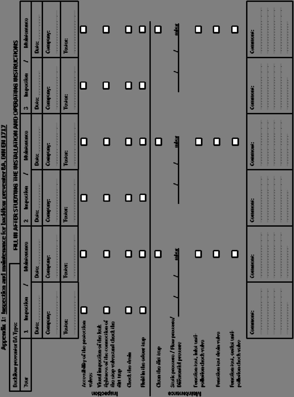
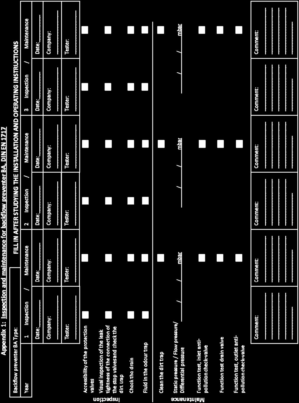
5 5. Inspection In compliance with standards on drinking water protection and hygiene regulations, the user/operating organisation is given the following specifications: As per DIN EN 1717, Point 4.6, perform regularly scheduled maintenance on the safeguards. As per DIN EN x annual maintenance is applicable Europe-wide. Check their proper functioning in regularly scheduled intervals in compliance with the national or regional stipulations. For DE, in accordance with DVGW W (April 2007) under 4.7 it is stipulated that the maintenance must be performed 1 x annually. For CH, perform the maintenance/inspection as per SVGW W3 Supplement 1 (2000), W/TPW 126 (April 1994) and W/TPW 135 (April 1994). In W/TPW 135, in Point 3 Maintenance, the maintenance/inspection is stipulated as periodical, but at least every 2 years. W/TPW 126 requires the backflow preventer BA to be checked for the first time after the first year of operation. In addition, Offprint no of SVGW 8/96 is pointed out. For NL, in VEWIN Waterwerkblad WB 1.4 G (November 2005 under Point 4 it is stipulated that backflow preventers BA need to be checked for proper operation and maintained 1x annually. The following applies: The functional and maintenance measures cover the function test, visual inspection of the interior parts and the cleaning or replacement of the functioning parts as stated under Points 3 and 4 in the operating instructions. This inspection should also include the related valves. Only authorised specialists are allowed to perform maintenance. Document the inspection on the attached control plate with date and signature. In addition, Appendix 1 on inspection and maintenance is recommended. Put the Backflow preventer BA cartridge through a visual inspection in the installed state during every maintenance to the extent this is possible through the housing opening. The manufacturer recommends replacing the cartridge every 10 years. Comply with local regulations. Measuring instrument for differential pressure measurement: Suitable differential pressure manometer; The KEMPER differential pressure measurement case, Figure , is recommended. 5.1 Connect test adapter - Screw on adapter G1/2-G1/4 - Screw on adapter G1/4 with plug-on coupling A B C - 5 -
6 5.2 Preparing the differential pressure manometer - Connect the test hose with the adapter *+* and *-* of the differential pressure manometer to each side. 5.3 Connect differential pressure manometer for function test inlet anti-pollution check-valve and drain valve - For each test hose, plug on and latch a quick coupler to the adapter (bleeder valves must be closed on the hoses.) - Connect the test hose of Test valve A to the connection marked ``+``` on the differential pressure manometer. - Connect the test hose of Test valve B to the connection marked ``-``` on the differential pressure manometer. - A = Supply pressure zone, B = Middle pressure zone, C = Back pressure zone A B C 5.4 Function test, inlet anti-pollution check-valve - Connect measuring instrument as per Open Test valves A and B and vent the measurement lines through the bleeder valves on the test hoses. Then close the bleeder valves and leave Test valve A and B open. A B C - 6 -
7 - Close the stop valve before and after the valve. - Using the bleeder valve on the test hose (Test valve B), slowly bleed the pressure of the middle pressure zone and watch the differential pressure display at the same time. The differential pressure rises until the anti-pollution check-valve starts to open. The drain valve must not trigger during this. - Close the bleeder valve on the test hose (Test hose B). The differential pressure must remain constant. Note: During the measurement, it is mandatory that there is no flow in the backflow preventer BA! A B C 5.5 Function test, drain valve - Connect measuring instrument as per Open Test valves A and B and vent the measurement lines through the bleeder valves on the test hoses. Then close the bleeder valves and leave Test valve A and B open. A B C - Close stop valve before and after the valve - Using the bleeder valve on the test hose (Test valve A), slowly bleed the supply pressure of the supply pressure zone and watch the differential pressure display and drain valve at the same time. The drain valve must trigger before the display reaches the value 140 mbar (when the valve triggers, the differential pressure initially rises only slightly and then falls again)! - Close bleeder valve. The bleeder valve must be closed tightly again. A B C - 7 -
8 5.6 Connect differential pressure manometer and absolute pressure manometer for function test output anti-pollution check-valve - Connect the test hose from Test valve B to the connection marked ``-`` on the differential pressure manometer. - Connect absolute pressure manometer with adapter to Test valve C. A B C 5.7 Function test, outlet anti-pollution check-valve - Open the stop valve before and after the valve and fill the valve. - Read pressure on scale and write down the value. A B C - Close stop valves and use Test valve B and Bleeder valve B to depressurise the middle pressure zone. During this, it is possible that a slight pressure drop occurs on the scale due to "setting". - Wait at least 2 minutes. The outlet-side anti-pollution check-valve is leakproof when the pressure remains constant during this time. A B C - 8 -
9 6. Removal, installation and cleaning the drain valve Both anti-pollution check-valves and the drain valve can be removed for maintenance purposes. All work can be performed without removing the housing from the pipeline (inline service). Only authorised specialists are allowed to perform maintenance. 1. Close cut-off valves 1 and Reduce the pressure by opening the ball valves. 3. Unscrew pressure control line 14 on the drain valve. 4. After loosening the screws, pull down drain connection 7 and unscrew with the help of an oil filter strap. 5. Take off the drain valve. 6. If necessary, clean or replace. If no dirt particles are visible but a fault was observed while inspecting the drain valve (see Chapter 5.2), the drain valve should be replaced (see accessories/spare parts). Clean the area around the valve seat and the opening slot (e.g., by carefully blowing out) 7. Assemble in the reverse sequence. Grease the O-rings well with Unisilikon 250 or a grease that does not contain mineral oil. ATTENTION! Otherwise it is possible that the O-rings will be destroyed. Replace damaged O-rings, see Chapter 13, Spare parts 8. Close the ball valves. 9. Slowly open the cut-off valves. 10. Vent the system through the ball valves. 11. Check the drain valve, see Chapter Connect the dust plugs to the ball valves. Never dismantle the anti-pollution check valve and drain valve from each other. High danger of injury! Figure 7: Removal, installation and cleaning the drain valve - 9 -
10 6.1 Removal, installation and inspecting the anti-pollution check valve (refer to Figure 4) 1. Close cut-off valves 1 and Reduce pressure by opening ball valves 3, 4, and Take off cover. 4. Remove the anti-pollution check-valve. For DN , first unscrew the discharge anti-pollution check valve and then the supply anti-pollution check valve. You can obtain an assembly tool as an accessory. Danger of injury! The anti-pollution check-valve is spring preloaded. 5. Check for leakproofness by filling water from the rear. Leaky anti-pollution check-valves must be replaced. Repair is not possible. 6. Assemble in the reverse sequence. For DN : - grease O-ring and thread well on the anti-pollution check valve with Unisilikon 250. Do not damage the O-ring when installing. The tightening torque for the anti-pollution check-valve is Nm. 7. Close the ball valves. 8. Open the cut-off valves. 9. Vent the system through the ball valves. 10. Check the backflow preventer, see Chapters 5.1 to Connect the dust plugs to the ball valves. 7. Important information instructions for your safety Use the device solely in a technically flawless condition and as intended for use, safety and hazard aware while complying with the installation and operating instructions. Have all malfunctions that could impair safety repaired immediately. The BA Backflow Preventer, Figure 361, is intended solely for the application areas named in these installation and operating instructions. Any different use or use beyond and above that is considered non-intended usage. 8. Troubleshooting Errors Possible causes Remedy Other Strong pressure fluctuations in the water network. Install a water surge (hammer) damper behind the backflow preventer Fluctuating admission pressure Install a pressure reducer before the backflow preventer Supply-side anti-pollution check valve or drain valve is soiled Remove and clean anti-pollution check valve Leaky supply anti-pollution check valve Remove the anti-pollution check valve Drain valve does not close Deposits on the valve seat Remove the drain valve Damaged O-rings Remove drain valve and replace O-ring Leaky drain valve Remove the drain valve Drain valve does not open Clogged pressure control line Remove and clean the pressure control line Table 4: Troubleshooting 9. Technical data Total pressure drop: max. 1.0 bar at nominal flow Flow media: Water at 60 C Operating pressure: max. 10 bar Minimum supply pressure: 1.5 bar Ball valve connection: G ½ with connection size DN Connection sizes Weight ca. in kg Total length in mm Nominal flow rate in m³/h DN DN DN DN Table 5: Technical data


11 10. Flow diagram Connection sizes DN 65 to 150 Pressure drop in valve Δp (bar) Flowrate V (m3h) 11. Materials Housing Anti-pollution check-valve Other interior parts Compression spring Sealing disc Drain valve housing Drain valve, other interior parts Drain valve, compressed spring Drain valve, membrane Drain valve, sealing disc Drain valve Table 6: Materials EPDM POM EPDM EPDM 12. Accessories KEMPER differential pressure measuring case Differential pressure manometer in a representative aluminium case, ideal for inspecting and maintaining all KEMPER BA Backflow Preventers, Figures 360 and 361 Content of the Differential Pressure Measurement Kit, Figure G1/4 adapters with plug coupling 2 G1/2 and G1/4 adapters Differential pressure manometer with scale range to 1 bar 2 test hoses, preassembled with plug-and-socket connections and bleed valves 1 absolute pressure manometer with scale range to 10 bar
12 Replacement tools for anti-pollution check-valve For flange version DN For flange version DN 150 Assembly wrench DN 65-DN 100 Figure DN 150 Figure Spare parts Anti-pollution check valve, supply side Anti-pollution check valve, discharge side DN 65 DN 100 Figure , DN 65 - DN 100 Figure , DN 150 Figure DN 150 Figure Ball valve Gasket set Bleed valve DN 65 - DN 150 Figure DN 65 DN 100 Figure DN 65 DN 150 Figure DN 150 Figure K /14 Technical subject to change. Gebr. Kemper GmbH + Co. KG Metallwerke Harkortstr. 5 D Olpe Tel Fax Tinfo@kemper-olpe.deT
13 - 13 -
Serie ECO 3T. Threaded end back flow preventer with controllable reduced pressure zone. made in. Application fields. Protection E U R O P E
 Serie ECO T Threaded end back flow preventer with controllable reduced pressure zone BRANDONI made in E U R O P E Application fields WATER FIRE FIGHTING DRINKING WATER 74 www.brandoni.it Serie ECO T The
Differential Pressure Regulator Type Type 45-6 (0.1 to 1 bar, DN 15) Mounting and Operating Instructions EB 3226 EN
 Mounting and Operating Instructions EB 3226 EN") Differential Pressure Regulator Type 45-6 Type 45-6 (0.1 to 1 bar, DN 15) Mounting and Operating Instructions EB 3226 EN Edition March 2008 Contents Contents Page 1 Design and principle of operation...................
Differential Pressure Regulator Type 45-6 Type 45-6 (0.1 to 1 bar, DN 15) Mounting and Operating Instructions EB 3226 EN Edition March 2008 Contents Contents Page 1 Design and principle of operation...................
WE SAY: CLEANLY SEPARATED SYSTEMS = ELKO-MAT EDER!
 elko-mat BACKFLOW PREVENTER WE SAY: CLEANLY SEPARATED SYSTEMS = ELKO-MAT EDER! Technical datasheet Ver.02/2017-en 1. Safety guidelines Follow the installation instructions Use the appliance according to
Serie ECO 3F. Flanged back flow preventer with controllable reduced pressure zone. made in. Application fields. Protection
 Flanged back flow preventer with controllable reduced pressure zone made in Application fields WATER FIRE FIGHTING DRINKING WATER 64 www.brandoni.it The ECO 3F flanged backflow preventers, which have a
Mounting and Operating Instructions EB 2558 EN. Self-operated Pressure Regulators. Type Pressure Build-up Regulator
 Self-operated Pressure Regulators Type 2357-31 Pressure Build-up Regulator with safety function and integrated excess pressure valve Type 2357-31 with non-return unit at port C Ports A and B with soldering
Operation manual Euro system separator GENO -DK 2 Euro system separator GENO -DK 2-Maxi Euro system separator GENO -DK-Maxi
 Operation manual Euro system separator GENO -DK 2 Euro system separator GENO -DK 2-Maxi Euro system separator GENO -DK-Maxi Euro system separator GENO -DK 2 nominal diameter DN 15/20 Euro system separator
Pressure Reducing Valve for Steam Type 2333 A
 Pressure Reducing Valve for Steam Type 2333 A Fig. 1 Type 2333 A 1. Design and principle of operation The pressure reducing valve consists of a balanced control valve and a closing actuator equipped with
Bermad Pressure Reducing. Model: 42T
 Bermad Pressure Reducing Pilot Operated Pressure Control Valve Model: 42T Installation Operation Maintenance Manual (IOM) REV. 27.7.17 Page 1 of 12 Safety First BERMAD believes that the safety of personnel
USM21 Sealed Bimetallic Steam Trap for use with Pipeline Connectors Installation and Maintenance Instructions
 6250250/1 IM-P625-03 ST Issue 1 USM21 Sealed Bimetallic Steam Trap for use with Pipeline Connectors Installation and Maintenance Instructions 1. General safety information 2. General product information
Mounting and Operating Instructions EB 3007 EN. Self-operated Pressure Regulators. Differential Pressure Regulators (opening) Type Type 42-25
 Type Type 42-25") Self-operated Pressure Regulators Differential Pressure Regulators (opening) Type 42-20 Type 42-25 Type 42-20 Differential Pressure Regulator Type 42-25 Differential Pressure Regulator Mounting and Operating
Self-operated Pressure Regulators Differential Pressure Regulators (opening) Type 42-20 Type 42-25 Type 42-20 Differential Pressure Regulator Type 42-25 Differential Pressure Regulator Mounting and Operating
1. Preface Important Safety Notes Brief Product Information Product Working Principle Installation Guidelines...
 Table of Contents 1. Preface...1 2. Important Safety Notes...1 3. Brief Product Information...3 4. Product Working Principle...5 5. Installation Guidelines...6 6. Startup and Commissioning...8 7. Maintenance
Model: 720-UL INSTALLATION OPERATION MAINTENANCE. Bermad Pressure Reducing Valve IOM. Model: FP -720-UL Sizes: 2"-12" BERMAD. Application Engineering
 Bermad Pressure Reducing Valve Model: 720-UL INSTALLATION OPERATION MAINTENANCE Application Engineering BERMAD 1. Safety First BERMAD believes that the safety of personnel working with and around our equipment
HUPF Series DESCRIPTION APPLICATION INSTRUCTION SHEET GAS PRESSURE REGULATOR WITH INCORPORATED FILTER EN1C-0003NL05 R1205.
 HUPF Series GAS PRESSURE REGULATOR WITH INCORPORATED FILTER INSTRUCTION SHEET DESCRIPTION Spring-loaded regulator with inlet pressure compensation and zero shut-off. The outlet pressure is kept constant
Mounting and Operating Instructions EB 2172 EN. Series 43 Temperature Regulators. Type 43-5 and Type Type Type 43-6
 Series 43 Temperature Regulators Type 43-5 and Type 43-7 Type 43-6 Type 43-6 Type 43-7 with flanged valve body, DN 32 to 50 Type 43-5 Type 43-7 with welding ends Mounting and Operating Instructions EB
WW-730. Pressure Sustaining/Relief Control Valve
 WW-730 Pressure Sustaining/Relief Control Valve Installation Operation & Maintenance Page 1 of 6 1. DESCRIPTION The Model 730 Pressure Relief / Sustaining Valve is an automatic control valve designed to
Declaration of Conformity as per Directive 97/23/EC
 Declaration of Conformity as per Directive 97/23/EC The manufacturer declares that:, 47906 Kempen, Germany Continuous, inline sampling valves Series 27f, with packing Operate with either; Star lever, or
Model: 43T. Bermad Pressure Relief Valve
 Model: 43T Bermad Pressure Relief Valve Installation Operation Maintenance Manual () Rev.C1_01.08.17 Page 1 of 10 Safety First BERMAD believes that the safety of personnel working with and around our equipment
Bladder Damper PP/PVC
 Operating instructions Bladder Damper PP/PVC EN Please carefully read these operating instructions before use. Do not discard. The operator shall be liable for any damage caused by installation or operating
Engineering Data Sheet
 Page 1 of 6 CE MARKING AND THE PRESSURE EQUIPMENT DIRECTIVE 97/23/EC Valves must be installed into a well designed system and it is recommended that the system be inspected in accordance with the appropriate
RS(H)10,15 USER MANUAL. Read the complete manual before installing and using the regulator.
10,15 USER MANUAL. Read the complete manual before installing and using the regulator.") RS(H)10,15 USER MANUAL Read the complete manual before installing and using the regulator. WARNING INCORRECT OR IMPROPER USE OF THIS PRODUCT CAN CAUSE SERIOUS PERSONAL INJURY AND PROPERTY DAMAGE. Due to
RS(H)10,15 USER MANUAL Read the complete manual before installing and using the regulator. WARNING INCORRECT OR IMPROPER USE OF THIS PRODUCT CAN CAUSE SERIOUS PERSONAL INJURY AND PROPERTY DAMAGE. Due to
Pressure relief valve
 Pressure relief valve Operating manual Series DHV 718 Version BA-2016.01.11 EN Print-No. 300 524 TR MA DE Rev001 ASV Stübbe GmbH & Co. KG Hollwieser Straße 5 32602 Vlotho Germany Phone: +49 (0) 5733-799-0
Pressure relief valve
 Pressure relief valve Operating manual Series DHV 712 R Version BA-2016.01.19 EN Print-No. 300 472 TR MA DE Rev001 ASV Stübbe GmbH & Co. KG Hollwieser Straße 5 32602 Vlotho Germany Phone: +49 (0) 5733-799-0
Declaration of Conformity as per Directive 97/23/EC
 Declaration of Conformity as per Directive 97/23/EC The manufacturer declares that:, 47906 Kempen, Germany Discontinous, inline sampling valves Series 27a and Series 27g, with packing with lever (180 )
Mounting and Operating Instructions EB 3017 EN. Self-operated Regulators
 Self-operated Regulars Flow and Differential Pressure Regular Type 42-37 Flow and Differential Pressure or Flow and Pressure Regular Type 42-39 Type 42-37 Type 42-39 Fig. 1 Flow and differential pressure
Mounting and Operating Instructions EB 3009 EN. Self-operated Regulators. Type RS Check Valve (backflow protection)
") Self-operated Regulators Type 42-10 RS Check Valve (backflow protection) Type 42-10 RS Check Valve (backflow protection) Mounting and Operating Instructions EB 3009 EN Edition December 2015 Definition
Self-operated Regulators Type 42-10 RS Check Valve (backflow protection) Type 42-10 RS Check Valve (backflow protection) Mounting and Operating Instructions EB 3009 EN Edition December 2015 Definition
OPERATING INSTRUCTIONS
 0/05 OPERATING INSTRUCTIONS for gas pressure regulators PN0 with integrated slam shut valve (SSV) and integrated limited capacity safety relief valve (RV) MR 25 F0, MR 25 SF0 p e 20 kpa - 0 MPa (0,2-0
INSTALLATION, OPERATION & MAINTENANCE MANUAL
 INSTALLATION, OPERATION & MAINTENANCE MANUAL AWWA C500 SOLID WEDGE GATE VALVE 2 72 NRS and OS&Y Series 100 and Series 105 TABLE OF CONTENTS SECTION PAGE # Equipment List 2 General 3 Receipt and Inspection
Pressure Limiting Valve SPVF Operating Instructions
 Pressure Limiting Valve SPVF Operating Instructions Industriehydraulik Contents Safety 1 Identification of safety instructions 1 General Safety Instructions 1 Address off Manufacturer 1 The Documentation
Mounting and Operating Instructions EB 3007 EN. Self-operated Pressure Regulators. Type Type Differential Pressure Regulators (opening)
") Self-operated Pressure Regulators Type 42-20 Type 42-25 Differential Pressure Regulators (opening) Translation of original instructions Type 42-20 Differential Pressure Regulator Type 42-25 Differential
Self-operated Pressure Regulators Type 42-20 Type 42-25 Differential Pressure Regulators (opening) Translation of original instructions Type 42-20 Differential Pressure Regulator Type 42-25 Differential
Installation & Operation Manual Proven Quality since 1892
 Content 1. ERIKS operating companies 2. Product description 3. Requirements for maintenance staff 4. Transport and storage 5. Function 6. Application 7. Installation 8. Maintenance 9. Service and repair
LRS(H)4 USER MANUAL. Read the complete manual before installing and using the regulator.
4 USER MANUAL. Read the complete manual before installing and using the regulator.") LRS(H)4 USER MANUAL Read the complete manual before installing and using the regulator. WARNING INCORRECT OR IMPROPER USE OF THIS PRODUCT CAN CAUSE SERIOUS PERSONAL INJURY AND PROPERTY DAMAGE. Due to the
LRS(H)4 USER MANUAL Read the complete manual before installing and using the regulator. WARNING INCORRECT OR IMPROPER USE OF THIS PRODUCT CAN CAUSE SERIOUS PERSONAL INJURY AND PROPERTY DAMAGE. Due to the
Inverted Bucket Steam Trap IB 16A-7
 Inverted Bucket Steam Trap IB 16A-7 Original Installation Instructions 819114-02 Contents Preface... 3 Availability... 3 Text layout... 3 Safety... 3 Usage for the intended purpose... 3 Basic safety notes...
WW-720. Pressure Reducing Control Valve
 WW-720 Pressure Reducing Control Valve (Size Ranges: 2-4 and 6-14 ) Installation Operation & Maintenance Page 1 of 6 1. DESCRIPTION The Model 720 Pressure Reducing is an automatic control valve (powered
Pneumatic proportional controller Types M Types FM Function tested for use of the float in Ex-zone 0
 Operating Manual LTIA5E Pneumatic proportional controller Types M Types FM Function tested for use of the float in Ex-zone 0 Contents 1. Safety Instructions 2. Conformity to standards 3. Technical data
VAG DUOJET Automatic Air Valve
 Operation and Maintenance Instructions VAG DUOJET Automatic Air Valve KAT-B 1912 Edition2 05-10 Contents 1 General 3 1.1 Safety 3 1.2 Proper use 3 1.3 Identification 3 VAG reserves the right to make technical
Operating and maintenance manual Filter and reducing station Series / 1.0
 Operating and maintenance manual Filter and reducing station Series 961 04.2017 / 1.0 Original instructions ARCA Regler GmbH. All rights reserved. Cover picture background: Freepik.com ARCA Regler GmbH
Installation and commissioning instructions 255 series and 256 series
 Installation and commissioning instructions 255 series and 256 series Table of contents 1 General information... 3 1.1 About these instructions... 3 1.2 About this product... 3 1.3 Appropriate usage...
Steam Trap BK 15 (DN40, DN 50) Original Installation Instructions English
 Original Installation Instructions English") Steam Trap BK 15 (DN40, DN 50) EN English Original Installation Instructions 810682-03 1 Contents Page Important Notes Usage for the intended purpose... 4 Safety note... 4 Danger... 4 Attention... 4 Application
Steam Trap BK 15 (DN40, DN 50) EN English Original Installation Instructions 810682-03 1 Contents Page Important Notes Usage for the intended purpose... 4 Safety note... 4 Danger... 4 Attention... 4 Application
PRS(TC)4,8 USER MANUAL. Read the complete manual before installing and using the regulator.
4,8 USER MANUAL. Read the complete manual before installing and using the regulator.") PRS(TC)4,8 USER MANUAL Read the complete manual before installing and using the regulator. WARNING INCORRECT OR IMPROPER USE OF THIS PRODUCT CAN CAUSE SERIOUS PERSONAL INJURY AND PROPERTY DAMAGE. Due to
PRS(TC)4,8 USER MANUAL Read the complete manual before installing and using the regulator. WARNING INCORRECT OR IMPROPER USE OF THIS PRODUCT CAN CAUSE SERIOUS PERSONAL INJURY AND PROPERTY DAMAGE. Due to
Pressure Relief Valve DHV 718
 Advantages frictionless components low maintenance low pressure increase up to fully opened valve constant low vibration controlling hermetically sealed by diaphragm for oscillating pumps for viscous media
Assembly Drawing: W-311B-A01, or as applicable Parts List: W-311B-A01-1, or as applicable Special Tools: , , &
 REDQ Regulators Model 411B Barstock Design Powreactor Dome Regulator OPERATION AND MAINTENANCE Contents Scope..............................1 Installation..........................1 General Description....................1
Ball Float Steam Trap UNA 43 PN 16/CL 125/JIS 10K UNA 46 PN 40/CL 150/CL 300/JIS 10K/JIS 20K DN 80, 100, 150, 3", 4", 6"
 Data Sheet 819584-00 Issue Date: 01/17 Ball Float Steam Trap UNA 43 PN 16/C 125/JIS 10K UNA 46 PN 40/C 150/C 300/JIS 10K/JIS 20K DN 80, 100, 150, 3", 4", 6" UNA 43 hl, UNA 46 hl UNA 43 v, UNA 46 v with
MAINTENANCE AND OPERATING MANUAL
 MAINTENANCE AND OPERATING MANUAL Cyclone condensate separator Type ASA EN EN Maintenance and operating manual Purpose and appropriate use Dear Customer, thank you for choosing our product. In order to
SRV66 Sanitary Pressure Reducing Valve
 1866350/4 IM-P186-09 CH Issue 4 SRV66 Sanitary Pressure Reducing Valve Installation and Maintenance Instructions 1. Safety information 2. General product information 3. Installation 4. Operation 5. Commissioning
Reduce pressure zone device suitable for high and medium hazard rated applications BSP screwed connections
 Reduce pressure zone device suitable for high and medium hazard rated applications BSP screwed connections Features General application The RP03 provides protection from both backsiphonage and backpressure
TECHNICAL DATA CAUTION
 Page 1 of 6 1. DESCRIPTION The Viking Model D-2 Accelerator is a quick-opening device, with an integral anti-flood assembly, used to increase the operating speed of a differential type dry pipe valve.
Instruction Manual SB02, SB03, SB04 All metal flow limiter
 Instruction Manual SB02, SB03, SB04 All metal flow limiter PKP Prozessmesstechnik GmbH Borsigstraße 24 D-65205 Wiesbaden-Nordenstadt Tel.: ++49-(0)6122-7055-0 Fax: ++49-(0)6122-7055-50 Email: info@pkp.de
Materials : Brass body dezincification-resistant
 Size : Ends : Min Temperature : Max Temperature : DN 1/2" to 3/4" Female female BSP + 5 C + 65 C Max Pressure : 10 Bars Specifications : Brass body dezincification-resistant Non Controlable With female
Wastewater combination air valve in stainless steel AISI 316 Mod. SCS
 Wastewater combination air valve in Mod. SCS The air valve guarantees the proper operation of sewage/industrial lines allowing the entrance of large quantity of air in case of pipe bursting or draining,
CARTRIDGE FILTERS TECHNICAL MANUAL MT 080. Installation, commissioning and maintenance instructions. 08/02 Edition
 CARTRIDGE FILTERS TECHNICAL MANUAL MT 080 Installation, commissioning and maintenance instructions 08/02 Edition 1 2 CONTENTS 1.0 PAGE INTRODUCTION 1.1 MAIN FEATURES 1.2 OPERATION 1.3 CLOSING OF HEAD WITH
Flowmeter. Original operating manual DFM
 Flowmeter Original operating manual Series DFM 165 350 Version BA-2016.08.09 EN Print-No. 300 458 TR MA DE Rev002 ASV Stübbe GmbH & Co. KG Hollwieser Straße 5 32602 Vlotho Germany Phone: +49 (0) 5733-799-0
WW-720. Pressure Reducing Control Valve
 WW-720 Pressure Reducing Control Valve (Size Ranges: 2-4 and 6-14 ) Installation Operation & Maintenance Page 1 of 6 1. DESCRIPTION The Model 720 Pressure Reducing is an automatic control valve (powered
Pressure-limiting valve and pre-load valve type MVG, MVE and MVP
 Pressure-limiting valve and pre-load valve type MVG, MVE and MVP Product documentation Directly controlled Operating pressure pmax: Flow rate Qmax: 700 bar 8 lpm D 3726 02-2016-1.3 by HAWE Hydraulik SE.
book : t95575.fm Seite 1 Mittwoch, September 20, :10 AM. Avensys. Exposed Single Lever Mixer
 955751.book : t95575.fm Seite 1 Mittwoch, September 20, 2000 10:10 AM Avensys Exposed Single Lever Mixer 33 389 33 396 Installation Instructions and Operating Guide Please leave this document with the
Declaration of Conformity as per Directive 97/23/EC
 Declaration of Conformity as per Directive 97/23/EC The manufacturer declares that:, 47906 Kempen, Germany Multi-way diverting valves Series 29a and Series 29b, with packing with lever 1. The valves are
VALFONTA INSTRUCTIONS: OPERATION AND INSTALLATION PRESSURE REDUCING VALVE MODEL PRV44
 INSTRUCTIONS: OPERATION AND INSTALLATION PRESSURE REDUCING VALVE MODEL PRV44 Pressure Reducing Valve PRV44 - Operation and Installation - 1 - manual PRV44-16-ENG JULY 2016 INDEX PAGE 1 IDENTIFICATION PLATE
Instruction Manual Contact Pressure Vacuum Gauge
 MS10 Instruction Manual Contact Pressure Vacuum Gauge Table of Contents 1. Safety Instructions 2. Intended Applications 3. Product Description and Functions 4. Installation 5. Commissioning 6. Maintenance
Steam trap BK 37 BK 28 BK 29 BK 37 ASME BK 28 ASME BK 29 ASME
 Steam trap BK 37 BK 28 BK 29 BK 37 ASME BK 28 ASME BK 29 ASME Original Installation Instructions 818689-05 Contents Foreword... 3 Availability... 3 Formatting features in the document... 3 Safety... 3
VALVCHEQ BACKFLOW PREVENTERS FIGURE RP03
 Reduce pressure zone device suitable for high and medium hazard rated applications BSP screwed connections FEATURES GENERAL APPLICATION The RP03 provides protection from both backsiphonage and backpressure
DN 65 to 100 R.F. PN10 flanges + 5 C + 65 C Max Pressure : 10 Bars Specifications : Brass check valve Controlable With valves DN1/2
 Size : Ends: Min Temperature : Max Temperature : DN 65 to 100 R.F. PN10 flanges + 5 C + 65 C Max Pressure : 10 Bars Specifications : Brass check valve Controlable With valves DN1/2 Materials : Bronze body
Welker Sampler. Model GSS-1. Installation, Operation, and Maintenance Manual
 Installation, Operation, and Maintenance Manual Welker Sampler Model GSS-1 The information in this manual has been carefully checked for accuracy and is intended to be used as a guide to operations. Correct
Type 2000 INOX. Quickstart. English Deutsch Français. 2/2-way angle seat valve 2/2-Wege Schrägsitzventil Vanne à siège incliné 2/2 voies
 Type 2000 INOX 2/2-way angle seat valve 2/2-Wege Schrägsitzventil Vanne à siège incliné 2/2 voies Quickstart English Deutsch Français Contents 1 QUICKSTART... 2 2 CONTACT ADDRESS... 2 3 INTENDED USE...
Mounting and Operating Instructions EB 2555 EN. Self-operated Pressure Regulators. Pressure Reducing Valves Type 50 ES Type 50 EM.
 Self-operated Pressure Regulators Pressure Reducing Valves Type 50 ES Type 50 EM Type 50 ES Type 50 EM Fig. 1 Pressure reducing valves Mounting and Operating Instructions EB 2555 EN Edition November 2011
Gas Pressure Regulator HON 300
 Product information serving the gas industry worldwide Applications, characteristics, technical data Applications direct acting gas pressure regulator, for systems in accordance with DVGW working instruction
STAINLESS STEEL LOW PRESSURE REDUCING VALVE LPRV ELITE
 MAIN CHARACTERISTICS The stainless steel LPRV elite low pressure reducer is intended for the pressure reduction of the fluids such as water, air, clear liquids not in charge of and the compatible gases
Art PRESSURE REDUCER
 FUNCTION ICMA pressure reducers are devices that reduce and stabilize the incoming pressure from the water supply. Pressure reducers allow correct use on domestic systems, reducing malfunctions due to
KTM 50 (DN ) Installation, maintenance and operating instructions
 Installation, maintenance and operating instructions") 52 762-306 09.2014 KTM 50 (DN 100-200) Installation, maintenance and operating instructions General High-performing and compact, these pressure-independent control valves for variable flow heating and
52 762-306 09.2014 KTM 50 (DN 100-200) Installation, maintenance and operating instructions General High-performing and compact, these pressure-independent control valves for variable flow heating and
Operating instruction
 Operating instruction MV, XV, HG, HP, RKO, D2G, TV, BV, WB & SLV 1 Introduction 2 2 Stafsjö s knife gate valves 2 3 Technical information 2 3.1 Pressure test 2 3.2 Labelling 2 4 Storage 3 5 Transportation
Manual Actuated Boiler Blowdown Valves
 Manual Actuated Boiler Blowdown Valves Installation and Maintenance Instructions 1. Safety information 2. General product information 3. Installation 4. Operation 5. Maintenance 6. Spare parts p.1 1. Safety
VALVES HIDROMATIC VALVE.
 VALVES HIDROMATIC VALVE Hydrodynamic design The Hidromatic valve of Hidroconta is a piston hydraulic valve controlled with the same fluid of the conduction. Its balloon design improves its hydrodynamic
TD45 Thermodynamic Steam Trap Installation and Maintenance Instructions
 0685255/1 IM-P068-47 ST Issue 1 TD45 Thermodynamic Steam Trap Installation and Maintenance Instructions 1 General safety information 2 General product information 3 Installation 4 Commissioning 5 Operation
Installation, operation & maintenance manual - original version
 Installation, operation & maintenance manual - original version AVK gate valves for water and wastewater Series 01, 02, 06, 12, 15, 18, 20, 26, 32, 33, 36, 38, 50, 55 and 636 COPYRIGHT AVK GROUP A/S 2018
Pneumatic switch module 3/2-way valve (On/Off) Types P Types FP Function tested for use of the float in Ex-zone 0
 Types P Types FP Function tested for use of the float in Ex-zone 0") Operating Manual LTIA3E Pneumatic switch module 3/2-way valve (On/Off) Types P Types FP Function tested for use of the float in Ex-zone 0 Contents 1. Safety Instructions 2. Conformity to standards 3. Technical
Operating Manual LTIA3E Pneumatic switch module 3/2-way valve (On/Off) Types P Types FP Function tested for use of the float in Ex-zone 0 Contents 1. Safety Instructions 2. Conformity to standards 3. Technical
Direct Operated Precision Regulator Modular Style. Standard Specifications
 1 Direct Operated Precision Regulator Modular Style Series P3 Courtesy of Steven Engineering, Inc.-23 Ryan Way, South San Francisco, CA 948-637-Main Office: (65) 588-92-Outside Local Area: (8) 258-92-www.stevenengineering.com
Mounting and operating instructions EB 2530 EN. Self-operated Pressure Regulator. Pressure Reducing Valve Type M 44-2
 Self-operated Pressure Regulator Pressure Reducing Valve Type M 44-2 Type M 44-2, connection G 1 4, K VS = 0.15 Type M 44-2, connection G 1, K VS = 6 Fig. 1 Type M 44-2 Pressure Reducing Valve Mounting
Operating manual Steam trap
 Operating manual Steam trap Blatt Nr. KA/4.0.181.1.1 Stand 12.03.2018 Contents Section Title Page 0 Introduction... 1 1 Intended use......1 2 Marking of the fitting... 2 3 Safety instructions... 2-3 4
Installation, Operating and Maintenance Manual Overflow Regulator Type 94/ 94 E
 Installation, Operating and Maintenance Manual Overflow Regulator Type 94/ 94 E Table of content 1. General information on installation, operating and maintenance instructions 1.1 Hazard notices 1.2 Qualified
Mounting and Operating Instructions EB EN. Type Supply Pressure Regulator. with increased air capacity
 Type 4708-45 Supply Pressure Regulator with increased air capacity Translation of original instructions Mounting and Operating Instructions EB 8546-1 EN Edition March 2016 Note on these mounting and operating
Crosby style JCE Safety Valve Installation, Maintenance and Adjustment Instructions CROSBY
 CROSBY Table of contents 1. Installation 1 1.1. Drainage 1 1.2. Discharge pipework 1 1.3. Preparation for installation 1 2. Pressure adjustment 1 3. Maintenance 1 4. Dismantling 1 4.1. All valve types
Mounting and Operating Instructions EB 8546 EN. Supply Pressure Regulator Type Fig. 1 Supply pressure regulators
 Supply Pressure Regulator Type 4708 Type 4708-5352 on Type 3730 Positioner Type 4708-52 with filter receptacle Type 4708-6252 on Type 3372 ctuator Fig. Supply pressure regulators Mounting and Operating
Model 420-HY Pressure Regulating Hydrant Valve
 Model 420-HY Pressure Regulating Hydrant Valve INSTALLATION OPERATION MAINTENANCE 1. Safety First BERMAD believes that the safety of personnel working with and around our equipment is the most important
553 Series.
 38467.03 www.caleffi.com Pre-adjustable filling units Copyright 01 Caleffi 3 Series Function The automatic filling valve is a device consisting of a pressure reducing valve with compensating seat, visual
Materials : Brass body dezincification-resistant up to DN1 1/4
 Size : Ends : Min Temperature : Max Temperature : DN 1/2" to 2" Male, Male BSP + 5 C + 65 C Max Pressure : 10 Bars Specifications : Brass body dezincification-resistant up to DN1 1/4 Controlable With male
AIR HAMMERS MODEL NO: CAT138/CAT139 OPERATING & MAINTENANCE INSTRUCTIONS PART NO: / GC064
 AIR HAMMERS MODEL NO: CAT138/CAT139 PART NO: 3120152 /3120153 OPERATING & MAINTENANCE INSTRUCTIONS GC064 INTRODUCTION Thank you for purchasing this CLARKE Air Hammer. Before attempting to use this product,
SCA Series Inverted Bucket Steam Traps
 0770050/5 IM-P077-06 ST Issue 5 SCA Series Inverted Bucket Steam Traps Installation and Maintenance Instructions 1. General safety information 2. General product information 3. Installation 4. Commissioning
Reduce pressure zone device suitable for high and medium hazard rated applications Flanged end connections
 VALVCHEQ Backflow Preventers Reduce pressure zone device suitable for high and medium hazard rated applications Flanged end connections Features General application The RP03 provides protection from both
TD62LM and TD62M Thermodynamic Steam Traps with Replaceable Seats
 0686550/4 IM-P068-58 ST Issue 4 TD62LM and TD62M Thermodynamic Steam Traps with Replaceable Seats Installation and Maintenance Instructions 1. Safety information 2. General product information 3. Installation
Siphon vessel / Priming aid
 Manufacturer: sera GmbH sera-straße 1 34376 Immenhausen Germany Tel.: +49 5673 999-00 Fax: +49 5673 999-01 info@sera-web.com Keep the operating manual for future use! Record the exact type and serial number
TEST BENCH SAFETY VALVES ¼ - 5 DN10 DN125
 TEST BENCH SAFETY VALVES ¼ - 5 DN10 DN125 Model: VC-40-VYC Table of contents 1. - Installing the test bench 1.1.1- Connecting the compressed air / nitrogen source 1.1.2- Maximum test pressure according
Latvin Luxury Shower Panel. Telephone Product Specification. ~ Minimum Working Pressure 1.0 bar ~ Maximum Working Pressure 3.
 Product Specification ~ Minimum Working Pressure 1.0 bar ~ Maximum Working Pressure 3.0 bar Latvin Luxury Shower Panel ~ Fixing Centres 150mm +/- 10mm ~ Outlet size 1/2" Bottom Outlet Always maintain a
Declaration of Conformity as per Directive 97/23/EC and Manufacturer s Declaration as per Directive 98/37/EC
 Declaration of Conformity as per Directive 97/23/EC and Manufacturer s Declaration as per Directive 98/37/EC The manufacturer declares that:, 47906 Kempen, Germany Continuous, PFA-lined, inline sampling
KBV21i and KBV40i Key Operated Boiler Blowdown Valves Installation and Maintenance Instructions
 4059051/3 IM-P405-48 EMM Issue 3 KBV21i and KBV40i Key Operated Boiler Blowdown Valves Installation and Maintenance Instructions 1. Safety information 2. General product information 3. Installation 4.
Type /2-Way Globe Valve 3/2-Wege-Geradsitzventil Vanne à siège droit 3/2 voies Operating Instructions Bedienungsanleitung Manuel d utilisation
 3/2-Way Globe Valve 3/2-Wege-Geradsitzventil Vanne à siège droit 3/2 voies Operating Instructions Bedienungsanleitung Manuel d utilisation We reserve the right to make technical changes without notice.
Testing Procedures & Trouble Shooting Guide Reduced Pressure Zone Assembly (1/2, 3/4", 1, 1 1/4, 1 1/2" & 2 )
") Testing Procedures & Trouble Shooting Guide Reduced Pressure Zone Assembly (1/2, 3/4", 1, 1 1/4, 1 1/2" & 2 ) First Check Valve Test 1) Bleed all test cocks. First open test cock 4, make sure it is slightly
Testing Procedures & Trouble Shooting Guide Reduced Pressure Zone Assembly (1/2, 3/4", 1, 1 1/4, 1 1/2" & 2 ) First Check Valve Test 1) Bleed all test cocks. First open test cock 4, make sure it is slightly
Hand pump type CH. Product documentation. 300 bar 8.3 cm 3 /stroke. Operating pressure p max : Displacement volume V max stroke :
 Hand pump type CH Product documentation Operating pressure p max : Displacement volume V max stroke : 300 bar 8.3 cm 3 /stroke D 7147 CH 04-2018-1.1 by HAWE Hydraulik SE. The reproduction and distribution
DN 50 REGULATOR SUTON 5000A1 REGULATOR SUTON 5000D1
 www.apq.com.es EU Product / Spain DN 50 REGULATOR SUTON 5000A1 REGULATOR SUTON 5000D1 Cod. RISUT5000A1 Cod. RISUT5000D1 DESCRIPTION The Suton 50001 Regulator is designed for use in distribution networks
MT-239-E ENGLISH PRESSURE REGULATOR STAFLUX MINI TECHNICAL MANUAL INSTALLATION, COMMISSIONING AND MAINTENANCE INSTRUCTIONS
 MT-239-E ENGLISH PRESSURE REGULATOR STAFLUX MINI TECHNICAL MANUAL INSTALLATION, COMMISSIONING AND MAINTENANCE INSTRUCTIONS Technical manual MT 239-E 1 STAFLUX MINI Technical manual MT 239-E 2 Technical
Modular valve block. Operating manual Series MVB 100/200. Version BA EN Print-No TR MA DE Rev001
 Modular valve block Operating manual Series MVB 100/200 Version BA-2016.04.20 EN Print-No. 300 627 TR MA DE Rev001 ASV Stübbe GmbH & Co. KG Hollwieser Straße 5 32602 Vlotho Germany Phone: +49 (0) 5733-799-0
299H Series. Introduction. P.E.D. Categories. Specifications. Installation. Warning. Installation Guide English September 2012
 Installation Guide English September 2012 299H Series Introduction This Installation Guide provides instructions for installation, startup, and adjustment of 299H Series regulators. To receive a copy of
Operation and Maintenance Instructions. VAG PICO Pilot Operated Control Valve
 Operation and Maintenance Instructions VAG PICO Pilot Operated Control Valve KAT-B 2032 Edition 1-2 - 01/2018 Table of Contents 1 General 3 1.1 Safety 3 1.2 Proper use 3 1.3 Identification 4 VAG reserves