266 with PROFIBUS PA Communication 2600T Series Pressure Transmitter. Engineered solutions for all applications
|
|
|
- Ethan Matthews
- 6 years ago
- Views:
Transcription

1 Operating Instruction OI/266/PB-EN Rev. D 266 with PROFIBUS PA Communication 2600T Series Pressure Transmitter Engineered solutions for all applications
2 The Company We are an established world force in the design and manufacture of measurement products for industrial process control, flow measurement, gas and liquid analysis and environmental applications. As a part of ABB, a world leader in process automation technology, we offer customers application expertise, service and support worldwide. We are committed to teamwork, high quality manufacturing, advanced technology and unrivalled service and support. The quality, accuracy and performance of the Company s products result from over 100 years experience, combined with acontinuous program of innovative design and development to incorporate the latest technology.
3 Contents Contents 1. Introduction Instruction manual structure Models covered by this manual Product description Safety General safety information Improper use Technical limit values Warranty prevision Use of instruction Operator liability Qualified personnel Returning devices Disposal Information on WEEE Directive 2002/96/EC Transport and storage Safety information for electrical installation Safety information for inspection and maintenance Transmitter overview Transmitter components overview Range & Span consideration Opening the box Identification Optional wired-on SST plate (I1) Handling Storage Mounting General IP protection & designation Mounting the transmitter Transmitter factory configuration Hazardous area considerations Pressure Equipment Directive (PED) (97/23/CE) Devices with PS > Devices with PS 200 bar Mounting a Differential Pressure sensor transmitter Bracket mounting (optional) B2 Pipe and wall mounting bracket details B5 Flat type bracket details Mounting a P style pressure transmitter B1 and B2 Barrel housing bracket details B2 DIN Housing bracket details Transmitter housing rotation Integral display rotation Impulse piping connection for standard instruments Process connections considerations Kynar inserts connection Screw torques for models with Kynar inserts Installation recommendations Steam or liquids flow measurement Gas or liquid flow measurement Level measurements (dry leg) Level measurements (wet leg) Level measurements on open tanks Pressure measurement of a tank Pressure measurement of a liquid in a pipe Pressure of a condensable vapor in a pipe Pressure measurement of a gas in a pipe PROFIBUS PA Communication Protocoll Profibus definition System architecture ABB solution Device introduction Feature overview Transmitter wiring Cable connection PROFIBUS wiring procedure PROFIBUS wiring procedure Grounding Protective grounding Integrated lightning protection (optional) T Series Pressure transmitters OI/266/PB-EN Rev. D 3
4 Contents 8 PROFIBUS electronics Fault protection On-board switches Factory default configuration Local push buttons Installing/Removing the external pushbuttons Operations Wet ranging operation (SW 3 = 1) PV Scaling operation (SW 3 = 0) HMI Local Indicator Installing / Removing the LCD display Integral display rotation Operations HMI as variable indicator HMI as diagnostic indicator HMI as feedback of the local operations HMI as configuration tool Commissioning Correction of the mounting position Configuration Network configuration Device configuration Factory settings User setting Operations Sensor trimming / calibration P-dP sensor low trimming P-dP sensor high trimming Static pressure low trimming Static pressure high trimming) Sensor temperature trimming Parallel shift (P-dP) Parallel shift (Static Pressure) Transfer function Transfer functions description Savings Reset PILD Algorithm Overview Block diagram Description Training phase Monitoring phase Device Block Diagram Maintenance Returns and removal Pressure transmitter sensor Removing / Installing the process flanges Pressure transducer replacement Hazardous Area considerations Ex Safety aspects and IP Protection (Europe) Entities for L5 option Ex Safety aspects (North America) Applicable standards Classifications...55 Appendix A Device mapping...56 General explanatory remarks...56 Device Management...57 DIRECTORY_OBJECT_HEADER...57 COMPOSITE_LIST_DIRECTORY_ENTRIES...57 COMPOSITE_DIRECTORY_ENTRIES...57 PHYSICAL BLOCK (PB)...58 ANALOG INPUT (AI)...61 PRESSURE TRANSDUCER BLOCK (PRTB)...62 ADVANCED DIAGNOSTIC TRANSDUCER BLOCK (ADTB)..66 HMI TRANSDUCER BLOCK (HMITB)...68 Appendix B Device diagnostic table...70 Appendix C HMI structure...72 Easy Set-up...73 Device Set-up...75 Display...79 Calibrate...83 Diagnostics...84 Device info...86 Communication...87 Appendix D Troubleshooting...88 Trouble Sheet...91 Return Report...92 EC Declaration of Conformity OI/266/PB-EN Rev. D 2600T Series Pressure transmitters
5 1. Introduction Introduction 1.1 Instruction manual structure The present manual provides information on installing, operating, troubleshooting the 266 pressure transmitter. Every section of the present manual is specifically dedicated to the specific phase of the transmitter lifecycle starting from the receipt of the transmitter and its identification, passing to the installation, to the electrical connections, to the configuration and to the troubleshooting and maintenance operations. 1.2 Models covered by this manual The present manual can be used for all the 266 models with exception done for the 266C (multivariable version). 1.3 Product description The pressure transmitters model 266 is a modular range of field mounted, microprocessor based electronic transmitters, multiple sensor technologies. Accurate and reliable measurement of differential pressure, gauge and absolute pressure, flow and liquid level is provided, in the even most difficult and hazardous industrial environments. Model 266 can be configured to provide specific industrial output signals according to mA with HART digital communication. 2600T Series Pressure transmitters OI/266/PB-EN Rev. D 5
6 2 Safety 2 Safety 2.1 General safety information The Safety section provides an overview of the safety aspects to be observed for operation of the device. The device has been constructed in accordance with the state of the art and is operationally safe. It has been tested and left the factory in perfect working conditions. The information in the manual, as well as the applicable documentation and certificates, must be observed and followed in order to maintain this condition throughout the period of operation. Full compliance with the general safety requirements must be observed during operation of the device. In addition to the general information, the individual sections in the manual contain descriptions of processes or procedural instructions with specific safety information. Only by observing all of the safety information can you reduce to the minimum the risk of hazards for personnel and/or environment. These instructions are intended as an overview and do not contain detailed information on all available models or every conceivable event that may occur during setup, operation, and maintenance work. For additional information, or in the event of specific problems not covered in detail by these operating instructions, please contact the manufacturer. In addition, ABB declares that the contents of this manual are not part of any prior or existing agreements, commitments, or legal relationships; nor are they intended to amend these. All obligations of ABB arise from the conditions of the relevant sales agreement, which also contains the solely binding warranty regulations in full. These contractual warranty provisions are neither extended nor limited by the information provided in this manual. Caution. Only qualified and authorized specialist personnel should be charged with installation, electrical connection, commissioning, and maintenance of the transmitter. Qualified personnel are persons who have experience in installation, electrical wiring connection, commissioning, and operation of the transmitter or similar devices, and hold the necessary qualifications such as: Training or instruction, i.e., authorization to operate and maintain devices or systems according to safety engineering standards for electrical circuits, high pressures, and aggressive media Training or instruction in accordance with safety engineering standards regarding maintenance and use of adequate safety systems. For safety reasons, ABB draws your attention to the fact that only sufficiently insulated tools conforming to DIN EN may be used. Since the transmitter may form part of a safety chain, we recommend replacing the device immediately if any defects are detected. In case of use in Hazardous Area non sparking tools only must be employed. In addition, you must observe the relevant safety regulations regarding the installation and operation of electrical systems, and the relevant standards, regulations and guidelines about explosion protection. Warning. The device can be operated at high levels of pressure and with aggressive media. As a result, serious injury or significant property damage may occur if this device is operated incorrectly. 2.2 Improper use It is prohibited to use the device for the following purposes: As a climbing aid, e.g., for mounting purposes As a support for external loads, e.g., as a support for pipes. Adding material, e.g., by painting over the name plate or welding/soldering on parts Removing material, e.g., by drilling the housing. Repairs, alterations, and enhancements, or the installation of replacement parts, are only permissible as far as these are described in the manual. Approval by ABB must be requested for any activities beyond this scope. Repairs performed by ABB-authorized centers are excluded from this. 2.3 Technical limit values The device is designed for use exclusively within the values stated on the name plates and within the technical limit values specified on the data sheets. The following technical limit values must be observed: The Maximum Working Pressure may not be exceeded. The Maximum ambient operating temperature may not be exceeded. The Maximum process temperature may not be exceeded. The housing protection type must be observed. 2.4 Warranty prevision Using the device in a manner that does not fall within the scope of its intended use, disregarding this manual, using underqualified personnel, or making unauthorized alterations, releases the manufacturer from any liability for any resulting damage. This makes the manufacturer s warranty null and void. 6 OI/266/PB-EN Rev. D 2600T Series Pressure transmitters
7 2 Safety 2.5 Use of instruction Danger <Serious damage to health/risk to life>. This message indicates that an imminent risk is present. Failure to avoid this will result in death or serious injury. Caution <Minor injuries>. This message indicates a potentially dangerous situation. Failure to avoid this could result in minor injuries. This may also be used for property damage warnings. Important. This message indicates indicates operator tips or particularly useful information. It does not indicate a dangerous or damaging situation. Warning <Bodily injury>. This message indicates a potentially dangerous situation. Failure to avoid this could result in death or serious injury Attention <Property damage>. This message indicates a potentially damaging situation. Failure to avoid this could result in damage to the product or its surrounding area. 2.6 Operator liability Prior to using corrosive and abrasive materials for measurement purposes, the operator must check the level of resistance of all parts coming into contact with the materials to be measured. ABB will gladly support you in selecting the materials, but cannot accept any liability in doing so. The operators must strictly observe the applicable national regulations with regard to installation, function tests, repairs, and maintenance of electrical devices. 2.9 Disposal ABB actively promotes environmental awareness and has an operational management system that meets the requirements of DIN EN ISO 9001:2000, EN ISO 14001:2004, and OHSAS Our products and solutions are intended to have minimum impact on the environment and persons during manufacturing, storage, transport, use and disposal. This includes the environmentally friendly use of natural resources. ABB conducts an open dialog with the public through its publications. This product/solution is manufactured from materials that can be reused by specialist recycling companies Information on WEEE Directive 2002/96/EC (Waste Electrical and Electronic Equipment) This product or solution is not subject to the WEEE Directive 2002/96/EC or corresponding national laws (e.g., the ElektroG - Electrical and Electronic Equipment Act - in Germany). Dispose of the product/solution directly at a specialist recycling facility; do not use municipal garbage collection points for this purpose. According to the WEEE Directive 2002/96/EC, only products used in private applications may be disposed of at municipal garbage facilities. Proper disposal prevents negative effects on people and the environment, and supports the reuse of valuable raw materials. ABB can accept and dispose of returns for a fee. 2.7 Qualified personnel Installation, commissioning, and maintenance of the device may only be performed by trained specialist personnel who have been authorized by the plant operator. The specialist personnel must have read and understood the manual and comply with its instructions. 2.8 Returning devices Use the original packaging or suitably secure shipping package if you need to return the device for repair or recalibration purposes. Fill out the return form (see the end of the document) and include this with the device. According to EC guidelines and other local laws for hazardous materials, the owner of hazardous waste is responsible for its disposal. The owner must observe the proper regulations for shipping purposes. All devices sent back to ABB must be free from any hazardous materials (acids, alkalis, solvents, etc.). 2600T Series Pressure transmitters OI/266/PB-EN Rev. D 7
8 2 Safety 2.11 Transport and storage After unpacking the pressure transmitter, check the device for transport damage. Check the packaging material for accessories. During intermediate storage or transport, store the pressure transmitter in the original packaging only. For information on permissible ambient conditions for storage and transport, see Technical data. Although there is no limit on the duration of storage, the warranty conditions stipulated on the order acknowledgment from the supplier still apply Safety information for electrical installation Electrical connections may only be established by authorized specialist personnel in accordance with the electrical circuit diagrams. The electrical connection information in the manual must be observed; otherwise, the applicable protection type may be affected. Ground the measurement system according to requirements Safety information for inspection and maintenance Warning Risk to persons. There is no EMC protection or protection against accidental contact when the housing cover is open. There are electric circuits within the housing which are dangerous if touched. Therefore, the auxiliary power must be switched off before opening the housing cover. Warning Risk to persons The device can be operated at high pressure and with aggressive media. Any process media released may cause severe injuries. Depressurize the pipeline/tank before opening the transmitter connection. Corrective maintenance work may only be performed by trained personnel. Before removing the device, depressurize it and any adjacent lines or containers. Check whether hazardous materials have been used as materials to be measured before opening the device. Residual amounts of hazardous substances may still be present in the device and could escape when the device is opened. Within the scope of operator responsibility, check the following as part of a regular inspection: Pressure-bearing walls/lining of the pressure device Measurement-related function Leak-tightness Wear (corrosion) 8 OI/266/PB-EN Rev. D 2600T Series Pressure transmitters
9 3 Transmitter Overview 3 Transmitter overview 3.1 Transmitter components overview 1 2 Figure 1: Differential pressure transmitter components TTG display (L5 option) 2 - LCD display (L1 option) 2 Figure 2: Gauge / absolute pressure transmitter components Important. These two pictures show only two different kinds of transmitters equipped with Barrel type housing. Please consider that DIN housings are available. 2600T Series Pressure transmitters OI/266/PB-EN Rev. D 9
10 3 Transmitter Overview 3.2 Range & Span consideration The 2600T Transmitter Specification Sheets provide all information concerning the Range and Span limits in relation to the model and the sensor code. The terminology currently used to define the various parameters is as follows: URL: Upper Range Limit of a specific sensor. The highest value of the measured value that the transmitter can be adjusted to measure. LRL: Lower Range Limit of a specific sensor. The lowest value of the measured value that the transmitter can be adjusted to measure. URV: Upper Range Value. The highest value of the measured value to which the transmitter is calibrated. LRV: Lower Range Value. The lowest value of the measured value to which the transmitter is calibrated. SPAN: The algebraic difference between the Upper and Lower Range Values. The minimum span is the minimum value that can be used without degradation of the specified performance. TD: (or Turn Down Ratio)is the ratio between the maximum span and the calibrated span. The transmitter can be calibrated with any range between the LRL and the URL with the following limitations: LRL LRV (URL - CAL SPAN) CAL SPAN MIN SPAN URV URL 10 OI/266/PB-EN Rev. D 2600T Series Pressure transmitters
: contains the certification related parameters for use in Hazardous area. The Nameplate (ref.")
 and temperature (TS). Please refer to the serial number when making enquiries to ABB service department. The optional additional SST Tag plate (ref.")
11 4 Opening the box 4.1 Identification The instrument is identified by the data plates shown in Figure 3. The certification plate (ref. A): contains the certification related parameters for use in Hazardous area. The Nameplate (ref.b) provides information concerning the model code, maximum working pressure, range and span limits, power supply, output signal, diaphragms material, fill fluid, range limit, serial number, maximum process working pressure (PS) and temperature (TS). Please refer to the serial number when making enquiries to ABB service department. The optional additional SST Tag plate (ref. C - code I2) also provides customer tag number and calibrated range. The instrument may be used as a pressure accessory (category III) as defined by the Pressure Equipment Directive 97/23/EC. In this case, near the CE mark, you will find the number of the notified body (0474) that have verified the compliance. 266 pressure transmitters are in compliance with EMC 2004/108/CE*. The certification plate (ref.a) shown here is issued by ABB S.p.A, Lenno, Italy, with the numbers: FM09ATEX0023X or IECEx FME X (Ex d) FM09ATEX0024X or IECEx FME X (Ex ia) FM09ATEX0025X or IECEx FME X (Ex nl) CE-Identification number of the notified bodies to Pressure Equipment Directive: 0474, to ATEX certification: 0722, to IECEx certification: IT/CES/QAR /02. 4 Opening the box The certification plate (ref.a) shown here may also be issued for ABB-APR, Minden, Germany, with the numbers: FM09ATEX0068X or IECEx FME X (Ex d) FM09ATEX0069X or IECEx FME X (Ex ia) FM09ATEX0070X or IECEx FME X (Ex nl) CE-Identification number of the notified bodies to Pressure Equipment Directive: 0045, to ATEX certification: 0044, to IECEx certification: DE/TUN/QAR /01. The same certification plate (ref.a) can be issued for ABB Limited, Faridabad, India, with the numbers: FM11ATEX0035X (Ex ia) FM11ATEX0036X (Ex d) FM11ATEX0037X (Ex nl) CE-Identification number of the notified bodies to ATEX certification: ABB Engineering Limited, Shanghai , P.R. China, can issue this certification plate (ref. A), as well. The numbers are: FM11ATEX0046X or IECEx FMG X (Ex ia) FM11ATEX0047X or IECEx FMG X (Ex d) FM11ATEX0048X or IECEx FMG X (Ex nl) CE-Identification number of the notified bodies to ATEX certification: ABB S.p.A. Made in Italy SERIAL\NUMBER B PRODUCT CODE SEAL-H SPEC.REQUEST SENSOR DIAPH.-FILL FLANGE/CONN.-GASKET/S H DIAPH.-FILL L DIAPH.-FILL SEAL POWER SUPPLY TS MWP/OVP LRL/URL SPAN LIMITS SEAL-L HW Rev. OUTPUT SIGNAL PS Local keys below label PED: MD: 2600T PRESSURE TRANSMITTER Calib. Range Tag Number C ABB S.p.A. Lenno (Co) Italy II 1/2 G Ex d IIC T6 - II 1/2 D Ex td A21 IP67 T85 C FM09ATEX0023X - IECEx FME X (-50 C<Ta<+75 C) POWER SUPPLY 42 Vdc/2W Max II 1 G Ex ia IIC T6 - II 1/2 G Ex ia IIC T6 - II 1 D Ex iad 20 T85 C and II 1/2 D Ex iad 21 T85 C for electrical parameters see cert. FM09ATEX0024X IP67 - IECEx FME X "FISCO Field Instrument" II 3 G Ex nl IIC T6 - II 3 D Ex td A22 IP67 T85 C Ui = 42Vdc Ii < 25mA Ci < 13nF Li < 0,22mH for electrical parameters see cert. FM09ATEX0025X IECEx FME X "FNICO Field Instrument" Figure 3: Product identification * C and F sensors on gauge and absolute pressure transmitters are in compliance with IEC with B criteria US US US FM APPROVED FM APPROVED FM APPROVED C C C General Purpose IP67 Max.Supply Voltage 42 Vdc XP (US) CL I/DIV1/GP ABCD, DIP CL II, III /DIV1/GP EFG, XP (Canada) CL I/DIV1/GP BCD, DIP CL II, III /DIV1/GP EFG, CL I, ZONE 1, AEx/Ex d IIC T4-50 C<Ta<+85 C ENCL 4X T AMB=85 C "Seal not required" - "DUAL SEAL" IS/Sec. Intrinseque (Entity) CL I, ZONE 0 AEx/Ex ia IIC T6,T5,T4 CL I/DIV1/GP ABCD IS - CL II/DIV1/GP EFG - CLIII DIV1 when conn. per dwg DH 3173 ENCL 4X "FISCO Field Instrument"-"DUAL SEAL" CL I, ZONE 2 AEx nc IIC T6,T5,T4 CL I, ZONE 2 Ex nl IIC T6,T5,T4 CL I/DIV2/GP ABCD NIFW when connected per drawing DH 3173 ENCL 4X "FNICO Field Instrument" - "DUAL SEAL" A 2600T Series Pressure transmitters OI/266/PB-EN Rev. D 11
12 4 Opening the box 4.2 Optional wired-on SST plate (I1) The 266 transmitter can be supplied with the optional Wired On Stainless Steel plate (figure 4) which is permanently laser printed with a custom text specified in phase of order. The available space consists in 4 lines with 32 characters per line. The plate will be connected to the transmitter with a Stainless Steel wire. 4.3 Handling The instrument does not require any special precautions during handling although normal good practice should be observed. 4.4 Storage The instrument does not require any special treatment if stored as dispatched and within the specified ambient conditions. There is no limit to the storage period, although the terms of guarantee remain as agreed with the Company and as given in the order acknowledgement. AAAAAAAAAAAAAAAAAAAAAAAAAAAAAAAA BBBBBBBBBBBBBBBBBBBBBBBBBBBBBBBB CCCCCCCCCCCCCCCCCCCCCCCCCCCCCCCC DDDDDDDDDDDDDDDDDDDDDDDDDDDDDDDD Figure 4: 4-line layout of the optional wired-on Stainless Steel plate 12 OI/266/PB-EN Rev. D 2600T Series Pressure transmitters
13 5 Mounting 5 Mounting 5.1 General Study these installation instructions carefully before proceeding. Failure to observe the warnings and instructions may cause a malfunction or personal hazard. Before installing the transmitter, check whether the device design meets the requirements of the measuring point from a measurement technology and safety point of view. This applies in respect of the: Explosion protection certification Measuring range Gauge pressure stability Temperature Operating voltage The suitability of the materials must be checked as regards their resistance to the media. This applies in respect of the: Gasket Process connection, isolating diaphragm, etc. In addition, the relevant directives, regulations, standards, and accident prevention regulations must be observed (e.g., VDE/ VDI 3512, DIN 19210, VBG, Elex V, etc.). Measurement accuracy is largely dependent on correct installation of the pressure transmitter and, if applicable, the associated measuring pipe(s). As far as possible, the measuring setup should be free from critical ambient conditions such as large variations in temperature, vibrations, or shocks. Important. If unfavorable ambient conditions cannot be avoided for reasons relating to building structure, measurement technology, or other issues, the measurement quality may be affected. If a remote seal with capillary tube is installed on the transmitter, the additional operating instructions for remote seals and the related data sheets must be observed. 5.2 IP protection & designation The housings for 266 transmitters are certified as conforming to protection type IP66 / IP67 (according toniec 60529) or NEMA 4X (according to NEMA 250). The first number indicates the type of protection the integrated electronics have against the entry of foreign bodies, including dust. 6 means that the housing is dust-proof (i.e., no ingress of dust). The second number indicates the type of protection the integrated electronics have against the entry of water. 6 means that the housing is protected against water; specifically, powerful jets of water under standardized conditions. 7 means that the housing is protected against water; specifically, against the effects of temporary immersion in water under standardized water pressure and temporal conditions. 5.3 Mounting the transmitter Transmitter factory configuration consideration The 266 pressure transmitter in your hands has been factory calibrated to reflect the published declared performance specification; no further calibration is required in normal condition. ABB typically configures 266 pressure transmitters according to the user requirements. A typical configuration includes: TAG number Calibrated span Output linearization LCD display configuration Hazardous area considerations The transmitter must be installed in hazardous area only if it is properly certified. The certification plate is permanently fixed on the neck of the transmitter top housing. The 266 Pressure Transmitter Line can have the following certifications: ATEX INTRINSIC SAFETY II 1 G Ex ia IIC T4/T5/T6 and II 1/2 G Ex ia IIC T4/T5/T6 II 1 D Ex iad 20 T85 C and II 1/2 D Ex iad 21 T85 C ATEX EXPLOSION PROOF II 1/2 G Ex d IIC T6 and II 1/2 D Ex td A21 IP67 T85 C ATEX TYPE N / EUROPE: II 3 G Ex nl IIC T4/T5/T6 and II 3 D Ex td A22 IP67 T85 C COMBINED ATEX, ATEX FM and FM Canada See detailed classifications FM Approvals US and FM Approvals Canada: Explosionproof (US): Class I, Div. 1, Groups A, B, C, D Explosionproof (Canada): Class I, Div. 1, Groups B, C, D Dust ignitionproof: Class II, Div. 1, Groups E, F, G Nonincendive: Class I, Div. 2, Groups A, B, C, D Intrinsically safe: Class I, II, III, Div. 1, Gr. A, B, C, D, E, F, G Class I, Zone 0, AEx ia IIC T6/T4 (FM US) Class I, Zone 0, Ex ia IIC T6/T4 (FM Canada) IEC (Ex): See detailed classifications INTRINSIC SAFETY/CHINA NEPSI approval Ex ia IIC T4-T6 FLAMEPROOF/CHINA NEPSI approval Ex d IIC T6 GOST (Russia), GOST (Kazakistan), Inmetro (Brazil) based on ATEX. 2600T Series Pressure transmitters OI/266/PB-EN Rev. D 13

. They have not been subject to a conformity validation.")
14 5 Mounting 5.4 Pressure Equipment Directive (PED) (97/23/CE) Devices with PS >200 Devices with a permissible pressure PS >200 bar have been subject to a conformity validation. The data label includes the following specifications: PRODUCT CODE SEAL-H SPEC.REQUEST SENSOR DIAPH.-FILL FLANGE/CONN.-GASKET/S H DIAPH.-FILL L DIAPH.-FILL SEAL POWER SUPPLY TS MWP/OVP LRL/URL SPAN LIMITS ABB S.p.A. Made in Italy SERIAL\NUMBER SEAL-L OUTPUT SIGNAL PS Local keys below label HW Rev. Figure 5: 266 nameplate with PED data Devices with PS 200 bar Devices with a permissible pressure PS 200 bar correspond to article 3 paragraph (3). They have not been subject to a conformity validation. These instruments were designed and manufactured acc. to SEP Sound Engineering Practices. 5.5 Mounting a Differential Pressure sensor transmitter (266DS/266MS/266PS/266DR/266PR/266MR) The pressure transmitter models 266DS, 266MS and 266PS can be mounted directly on the manifold. A mounting bracket for wall or pipe mounting (2 pipe) is also available as an accessory. For models 266DR, 266PR and 266MR always mounting brackets should be used. Ideally, the pressure transmitter should be mounted in a vertical position to prevent subsequent zero shifts. PED: MD: It is important to mount the transmitter and to lay the process piping so that gas bubbles, when measuring liquids, or condensate when measuring gases, will flow back to the process and not enter the transmitter measuring chamber. Optional Vent/drain valves (code V1/V2/V3) on the transmitter are located on the sensor flanges. The transmitter has to be positioned so that these drain/vent valves will be located higher than the taps on liquid service in order to allow the venting of entrapped gas or below the taps on gas service in order to allow the air to vent off or condensate to drain off. For safety reasons, take care of the drain/vent valves position so that when the process fluid is removed during the drain/vent operation it is directed down and away from technicians. It is recommended to mount the transmitter to prevent this possible source of damage for unskilled operators. Figure 6: Drain/vent valves configuration (respectively V1, V2, V3) Important. This message indicates indicates operator tips or particularly useful information. It does not indicate a dangerous or damaging situation. Important. In case of a High Static differential pressure transmitter, please notice that the Vent/Drain valves can be configured only on the process axis (V1). Important. If the transmitter is installed inclined with respect to the vertical, the filling liquid exerts hydrostatic pressure on the measuring diaphragm, resulting in a zero shift. In such an event, the zero point can be corrected via the zero push-button or via the set PV to zero command. Please refer to the [configuration section] for further details. For transmitters without diaphragm seals, please read the following considerations on the Vent/Drain. Attention Potential damage to transmitter. In case of a High Static differential pressure transmitter (266DSH.x.H) please always open the equalization valve of the manifold (if installed) before applying pressure to the transmitter. High Static pressure can damage the sensor causing a zero shift and a serious decrease of the total performance in terms of accuracy. In this case, please perform a full sensor trim. 14 OI/266/PB-EN Rev. D 2600T Series Pressure transmitters
15 5 Mounting Bracket mounting (optional) Different mounting brackets are available please refer to the relevant installation drawing below: 29 (1.14) 91 (3.58) 18 (0.71) 58 (2.28) 55 (2.17) 18 (0.71) 179 (7.02) 66 (2.60) with plug 78 (3.07) with d/v valve 11 (0.43) 210 (8.28) 89 (3.48) 72 (2.83) (*) 116 (4.57) 142 (5.59) 113 (4.45) Figure 7: Differential Pressure Style transmitter with barrel housing installed on a horizontal pipe with optional bracket (B2) 29 (1.14) 18 (0.71) 58 (2.28) 55 (2.17) 18 (0.71) 91 (3.58) 9 (0.35) 179 (7.02) 145 (5.70) 66 (2.60) with plug 78 (3.07) with d/v valve 41.3 (1.63) 65 (2.53) 210 (8.28) 54 (2.13) 96.8 (3.81) 100 (3.94) for NACE bolting 102 (4.02) 29 (1.12) Figure 8: Differential Pressure Style transmitter (High Static option) 2600T Series Pressure transmitters OI/266/PB-EN Rev. D 15
16 5 Mounting 29 (1.14) 91 (3.58) 18 (0.71) 58 (2.28) 55 (2.17) 18 (0.71) 179 (7.02) 11 (0.43) 210 (8.28) (*) 113 (4.43) 123 (4.86) 72 (2.83) 113 (4.45) 66 (2.60) with plug 78 (3.07) with d/v valve 142 (5.59) Figure 9: Differential Pressure Style transmitter with barrel housing installed on a vertical pipe with optional bracket (B2) 29 (1.14) 18 (0.71) 18 (0.71) 197 (7.73) 178 (6.99) 129 (5.06) 113 (4.45) 72 (2.83) 116 (4.57) 136 (5.35) 87 (3.42) 183 (7.19) 55 (2.17) Figure 10: Differential Pressure Style transmitter with DIN housing installed on a Vertical pipe with optional bracket (B2) installation for AIR/GAS measurements 16 OI/266/PB-EN Rev. D 2600T Series Pressure transmitters
17 5 Mounting 29 (1.14) 18 (0.71) 83 (3.28) 65 (2.54) 4.4 (0.17) 116 (4.57) 136 (5.35) 87 (3.42) 183 (7.19) 55 (2.17) 18 (0.71) Figure 11: Differential Pressure Style transmitter with barrel housing and Kynar inserts installed on a horizontal pipe with optional bracket (B2) 91 (3.58) 18 (0.71) 58 (2.28) 55 (2.17) 29 (1.14) 18 (0.71) 179 (7.02) 210 (8.28) 72 (2.83) 89 (3.48) 1/4 or 1/2 NPT 54 (2.13) 116 (4.57) 113 (4.45) Figure 12: Differential Pressure Style transmitter with barrel housing and Kynar inserts installed on a vertical pipe with optional bracket (B2) 2600T Series Pressure transmitters OI/266/PB-EN Rev. D 17
18 5 Mounting 91 (3.58) 18 (0.71) 58 (2.28) 55 (2.17) 29 (1.14) 18 (0.71) 179 (7.02) 210 (8.28) 54 (2.13) 113 (4.43) 123 (4.86) 72 (2.83) 113 (4.45) Figure 13: Differential Pressure Style transmitter with barrel housing and Kynar inserts installed on a vertical pipe with optional bracket (B2) B2 Pipe and wall mounting bracket details All the bolts and nuts supplied are necessary for the installation on pipe. In case of panel or wall installation, the U-bolt and the U-bolt nuts and washers will not have to be used. The bolts for panel mounting are not within the scope of supply U-bolt 2 U-bolt fixing bolt and washer 3 Transmitter fixing bolts 4 B2 bracket 4 1 Figure 14: Pipe and wall mounting bracket kit (B2) 18 OI/266/PB-EN Rev. D 2600T Series Pressure transmitters
19 5 Mounting 29 (1.14) 91 (3.58) 18 (0.71) 58 (2.28) 55 (2.17) 18 (0.71) 166 (6.53) 117 (4.60) 70 (2.75) 84 (3.31) 179 (7.02) 11 (0.43) 210 (8.28) (*) 70 (2.75) 142 (5.59) 95 (3.72) 174 (6.86) Figure 15: Differential Pressure Style transmitter with barrel housing installed on a box pipe with optional bracket for SST housing (B5) B5 Flat type bracket details 3 1 U-bolt 2 U-bolt fixing bolt and washer 3 Transmitter fixing bolts 4 B5 bracket Figure 16: Flat type mounting bracket kit (B5) 2600T Series Pressure transmitters OI/266/PB-EN Rev. D 19
20 5 Mounting 5.6 Mounting a P style pressure transmitter (266G, 266A, 266H, 266N) The pressure transmitter can be mounted directly on the manifold. A mounting bracket for wall or pipe mounting (2 pipe) is also available as an accessory. Ideally, the pressure transmitter should be mounted in a vertical position to prevent subsequent zero shifts. Important. If the transmitter is installed inclined with respect to the vertical, the filling liquid exerts hydrostatic pressure on the measuring diaphragm, resulting in a zero shift. In such an event, the zero point can be corrected via the zero push-button or via the set PV to zero command. Please refer to the [configuration section] for further details. For transmitters without diaphragm seals the Vent / Drain considerations below should be taken into consideration. 91 (3.58) 113 (4.45) 29 (1.14) 18 (0.71) 18 (0.71) 54 (2.13) 16 (0.63) 18 (0.71) 145 (5.71) 1/2-14 NPT 32 (1.26) width across flats of exagon 117 (4.60) Ø65 (2.56) 39 (1.54) 140 (5.54) 49 (1.93) Figure 17: Model 266H or 266N Hi overload resistant P-Style transmitter with barrel housing installed on a 2 pipe with optional bracket (B1 carbon steel or B2 Stainless Steel 316L) 111 (4.37) 29 (1.14) 18 (0.71) 18 (0.71) 91 (3.58) 55 (2.17) Max. 145 (5.71) Ø65 (2.56) 1/2-14 NPT CH (5.54) 70 (2.75) Figure 18: Model 266G or 266A P-Style transmitter with barrel housing installed on a 2 pipe with optional bracket (B1 carbon steel or B2 Stainless Steel 316L) 20 OI/266/PB-EN Rev. D 2600T Series Pressure transmitters
21 5 Mounting B1 and B2 Barrel housing bracket details 1 U-bolt U-bolt fixing bolt and washer 3 Transmitter fixing bolts 4 B1 or B2 bracket 2 3 Figure 19: Pipe and wall mounting bracket kit (B1 and B2) for P style transmitter with Barrel housing 128 (5.04) 85 (3.35) 18 (0.71) 29 (1.14) 18 (0.71) 122 (4.80) 66 (2.60) 30 (1.19) 72 (2.83) 54 (2.13) 11 (0.43) 16 (0.63) 72 (2.83) 18 (0.71) 145 (5.71) Ø65 (2.56) 49 (1.93) 39 (1.54) 1/2-14 NPT 32 (1.26) width across flats of exagon 117 (4.60) 105 (4.13) Figure 20: Model 266H or 266N Hi overload resistant P-Style transmitter with DIN housing installed on a 2 pipe with optional bracket (B2 Stainless Steel 316L) 2600T Series Pressure transmitters OI/266/PB-EN Rev. D 21
22 5 Mounting 91 (3.58) 113 (4.45) 29 (1.14) 18 (0.71) 18 (0.71) 283 (11.12) 19 (0.74) 12 (0.45) 145 (5.71) 72 (2.83) 116 (4.57) 105 (4.12) Ø65 (2.56) 23 (0.9) width across flats of exagon Figure 21: Model 266H or 266N High overload resistant P-Style transmitter with sensor Z with barrel housing installed on a 2 pipe with optional bracket (B6 carbon steel or B7 Stainless Steel 316L) Attention Potential damage to transmitter. In case of an HART gauge pressure transmitter with 1050 bar/15000 psi sensor range (266HSH.Z or 266GSH.Z) and 1/4 NPT process connection, please always perform sensor low trimming to remove possible zero shift and a prevent serious decrease of the total performance in terms of accuracy. Sensor low trim can be performed via LCD, DTM or handheld terminals B2 DIN Housing bracket details U-bolt 2 U-bolt fixing bolt and washer 3 Transmitter fixing bolts 4 B2 bracket 2 3 Figure 22: Pipe and wall mounting bracket kit (B2) for P style transmitter with DIN housing 22 OI/266/PB-EN Rev. D 2600T Series Pressure transmitters
23 5 Mounting 5.7 Transmitter housing rotation To improve field access to the wiring or the visibility of the optional LCD meter, the transmitter housing may be rotated through 360 and fixed in any position. A stop prevents the housing from being turned too far. In order to proceed with housing rotation, the housing stop tang-screw has to be unscrewed by approximately 1 rotation (do not pull it out) and, once the desired position has been reached, retightened. Figure 23: Housing rotation 5.8 Integral display rotation In case an optional integral display meter is installed, it is possible to mount the display in four different positions rotated clockwise or counterclockwise with 90 steps. To rotate the LCD, simply open the windowed cover (Hazardous area prescriptions must be respected), pull-out the display housing from the communication board.. Reposition the LCD connector according to the new desired position. Push back the LCD module on the communication board. Be sure that the 4 plastic fixing locks are properly in place. Although it is not absolutely necessary to use balancing vessels with vaporous measuring media, measures must be taken to prevent steam entering the measuring chambers of the measuring equipment (266Dx and 266Mx). It may be necessary to use condensate vessels, etc., with small spans and vaporous measuring media (266Dx and 266Mx). If using condensate vessels (steam measurement), you should ensure that the vessels are at the same elevation in the differential pressure piping (266Dx and 266Mx). As far as possible, keep both impulse lines at the same temperature (266Dx and 266Mx). Completely depressurize the impulse lines if the medium is a fluid. Lay the impulse lines in such a way that gas bubbles (when measuring fluids) or condensate (when measuring gases) can flow back into the process line. Ensure that the impulse lines are connected correctly (High and Low pressure sides connected to measuring equipment, seals...). Make sure the connection is tight. Lay the impulse line in such a way that prevents the medium from being blown out over the measuring equipment. Caution. Process leaks may cause harm or result in death. Install and tighten process connectors and all accessories (including manifolds) before applying pressure. In case of toxic or otherwise dangerous process fluid, take any precautions as recommended in the relevant Material Safety Data Sheet when draining or venting. Use only a 12 mm (15/32 ) hexagonal spanner to tighten the bracket bolts. 5.9 Impulse piping connection for standard instruments In order for the pipes to be laid correctly, the following points must be observed: The measuring pipes must be as short as possible and free from sharp bends. Lay the impulse piping in such a way that no deposits accumulate in them. Gradients should not be less than approx. 8% (ascending or descending). The measuring pipes should be blown through with compressed air or, better yet, flushed through with the measuring medium before connection. Where a fluid/vaporous measuring medium is being used, the liquid in both measuring pipes must be at the same level. If a separating liquid is being used, both measuring pipes must be filled to the same level (266Dx and 266Mx). 2600T Series Pressure transmitters OI/266/PB-EN Rev. D 23
 between the connections. The process connections on the transmitter flange are on centers to allow direct mounting to a three-valve or five-valve manifold.")
24 5 Mounting 5.10 Process connections considerations 266 differential pressure transmitter process connections on the transmitter flange are 1/4-18 NPT, with a centers distance of 54mm (2.13in) between the connections. The process connections on the transmitter flange are on centers to allow direct mounting to a three-valve or five-valve manifold. Flange adapter unions with 1/2-14 NPT connections are available as an option. Rotate one or both of the flange adapters to attain connection centers of 51mm (2.01in), 54mm (2.13in) or 57mm (2.24in). To install adapters, perform the following procedure: 1. Position the adapters with the O-ring in place. 2. Bolt the adapters to the transmitter using the bolts supplied. 3. Tighten the bolts to a torque value of 25Nm (stainless steel bolts) or 15Nm (for Stainless steel NACE bolts). Figure 24: Adapter Deviations for models 266Mx, 266Rx and for PTFE O-rings: pretightening hand-tight. Pretightening to 10 Nm. Final tightening to 50 Nm. For model 266PS, 266VS and 266RS, it is only possible to have one adapter, with low pressure side flange without process connection and drain/vent valve. For high static model (266DSH.x.H) tighten the bolts to a torque value of 40 Nm (regardless of the material of the bolts used). In case of PTFE O-rings, pretightening to 10Nm and final tightening to 50 Nm Kynar inserts connection When connecting Pressure transmitters equipped with kynar inserts tighten the bolts to 15 Nm max Screw torques for models 266MS and 266RS with Kynar inserts The following procedures apply to process flange screws and nuts: Pretightening to 2 Nm (working crosswise). Pretightening to 10 Nm (working crosswise) and then tightening by a tightening angle of 180, working in two stages of 90 for each screw, and working crosswise. Figure 25: Kynar insert 24 OI/266/PB-EN Rev. D 2600T Series Pressure transmitters
25 5 Mounting 5.13 Installation recommendations Impulse piping configuration depends on the specific measurement application Steam (condensable vapor) or clean liquids flow measurement Place taps to the side of the line. Mount beside or below the taps. Mount the drain/vent valve upward. In case of steam application fill the vertical section of the connecting lines with a compatible fluid through the filling tees. The process fluid must enter the transmitter primary: 1. Open equalizing valve (C) 2. Close low pressure (B) and high pressure (A) valves. 3. Open gate valves 4. Slowly open high pressure (A) valve to admit process fluid to both sides of primary. 5. Vent or drain the primary unit and then close the valves. 6. Open the (B) valve and close the equalizing valve Gas or liquid (with solids in suspension) flow measurement Place the taps to the top or side of the line. Mount the transmitter above the taps. The process fluid must enter the transmitter primary: 1. Open equalizing valve (C) 2. Close low pressure (B) and high pressure (A) valves. 3. Open gate valves 4. Slowly open high pressure (A) valve to admit process fluid to both sides of primary. 5. Vent or drain the primary unit and then close the valves. 6. Open the (B) valve and close the equalizing valve. Figure 27: Gas or liquid flow measurement (transmitter and manifold) Figure 26: Steam or clean liquid flow measurement (transmitter and manifold) 2600T Series Pressure transmitters OI/266/PB-EN Rev. D 25
26 5 Mounting Liquid level measurements on closed tanks and non condensable fluids (dry leg) Mount the transmitter at the same height or below the lowest level to be measured. Connect the + (H) side of the transmitter to the bottom of the tank. Connect the - (L) side of the transmitter to the upper part of the tank, above the maximum level of the tank. Figure 28: Level measurement on closed tank with dry leg Liquid level measurement with closed tanks and condensable fluids (wet leg) Mount the transmitter at the same height or below the lowest level to be measured. Connect the + (H) side of the transmitter to the bottom of the tank. Connect the - (L) side of the transmitter to the upper part of the tank. Fill the vertical section of the connecting line to the upper part of the tank with a compatible liquid through the dedicated filling tee. Figure 29: Level measurement on closed tank with wet leg Liquid level measurement with open tanks Mount the transmitter at the same height or below the lowest level to be measured. Connect the + (H) side to the bottom of the tank. Vent the (L) side of the transmitter to the atmosphere (in this case a gauge pressure is shown; the (L) side is already vented to the atmosphere). Figure 30: Level measurement on open tank with P style transmitter 26 OI/266/PB-EN Rev. D 2600T Series Pressure transmitters
27 5 Mounting Pressure or absolute pressure measurement of a tank Place the taps in the upper part of the tank. Mount the transmitter above the elevation of the process tap (both pressure and differential pressure transmitter can be used). Connect the transmitter to the tank Pressure or absolute pressure measurement of a liquid in a pipe Place the tap at the side of the line. Mount the transmitter (both pressure and differential pressure transmitters) beside or below the tap for clean fluids, above the tap for dirty fluids. Connect the + (H) side of the transmitter to the pipe. Figure 31: Gauge or absolute pressure measurement on a tank Figure 32: Gauge or absolute pressure measurement of a liquid in a pipe 2600T Series Pressure transmitters OI/266/PB-EN Rev. D 27
28 5 Mounting Pressure or absolute pressure measurement of a condensable vapor in a pipe Place the tap at the side of the line. Mount the transmitter (both pressure and differential pressure transmitter) below the tap. Connect the + (H) side of the transmitter to the pipe. Fill the vertical section of the connecting line to the tap with a compatible liquid through the dedicated filling tee Pressure or absolute pressure measurement of a gas in a pipe Place the tap at the top or side of the line. Mount the transmitter (both pressure and differential pressure transmitter) beside or above the tap. Connect the transmitter to the pipe. Figure 33: Gauge or absolute pressure measurement of condensable vapor Figure 34: Gauge or absolute pressure measurement of gas in a pipe 28 OI/266/PB-EN Rev. D 2600T Series Pressure transmitters
 for factory/plant instrumentation and control devices. Important.")
29 6 PROFIBUS PA Communication Protocoll 6 PROFIBUS PA Communication Protocoll 6.1 Profibus definition PROFIBUS is an all-digital, serial, two-way communication system that serves as a Local Area Network (LAN) for factory/plant instrumentation and control devices. Important. Further information on PROFIBUS PA can be found in the PNO Guideline and standards IEC 61158, IEC 61784, EN 50170/DIN and EN (FISCO model) see in the Profibus PNO website and/or from the ABB website System architecture ABB solution Class 1 Master Class 2 Master T T T T Figure 34: PROFIBUS architecture with bus termination (T) 2600T Series Pressure transmitters OI/266/PB-EN Rev. D 29
30 7 Device introduction 7.1 Feature overview The 2600T-266 PdP Profibus PA is compliant with the PNO Profile for Process Control Devices version 3.02 Class B [Ref. 2].The 2600T-266 PdP PROFIBUS PA is a compact slave device implementing: n 1 Physical Block, n 3 Analog Input function blocks n 1 Pressure Transducer Block n 1 HMI Transducer Block n 1 Advanced Diagnostic Transducer Block with PILD algorithm (Plugged Impulse Line Detection) Important. For convenience, all the device parameters mentioned in this document are written with the prefix indicating the block into where they are mapped: PB_ = Physical Block PRTB_ = Pressure Transducer Block ADTB_ = Advanced Diagnostic Transducer Block HMI_ = HMI Transducer Block AIx_ = Analog Input Function Blocks where the x is the number of the AI (1, 2, 3) For all the complete details about the device parameters and their mapping refer to the APPENDIX A at the end of this manual 7.2 Transmitter wiring Warning. Observe the applicable regulations governing electrical installation. Connections must only be established in a dead-voltage state. Since the transmitter has no switch-off elements, overvoltage protection devices, lightning protection, and voltage separation capacity must be provided at the plant (overvoltage/lightning protection is optional). Check that the existing operating voltage corresponds to the voltage indicated on the name plate. The same lines are used for both the power supply and output signal. In case the surge protection option is present and the transmitter is installed in a Hazardous area, the transmitter has to be power supplied from a voltage source isolated from mains (galvanic separation). Furthermore the potential equalization for the entire powering cable must be guaranteed since the intrinsic safety circuit of the transmitter is grounded. Warning. Electrical shock can result in death or serious injury. Avoid contact with the leads and terminals. High voltage that may be present on leads can cause electrical shock. Warning. Do NOT make electrical connections unless the electrical code designation stamped on the transmitter data plate agrees with the classification of the area in which the transmitter is to be installed. Failure to comply with this warning can result in fire or explosion. 7 Device introduction Cable connection Depending on the design supplied, the electrical connection is established via a cable entry, M20 x 1.5 or 1/2-14 NPT thread, or Han 8D plug (8U) (PROFIBUS PA and FOUNDATION Fieldbus: M12 x 1 or 7/8 plug). The screw terminals are suitable for wire cross sections of up to 2.5 mm2 (AWG 14). Important. With Category 3 transmitters for use in Zone 2, a qualified cable gland for this type of protection must be installed by the customer (see the section Hazardous Area Consideration ). An M20 x 1.5 threads is located in the electronics housing for this purpose. For transmitters with Flameproof enclosure (Ex d) type of protection, the housing cover must be secured using the locking screw. The screw plug that may have been supplied with the transmitter must be sealed at the plant using Molykote DX. The installer assumes responsibility for any other type of sealing medium used. At this point, we wish to draw your attention to the fact that increased force will be required to unscrew the housing cover after an interval of several weeks. This is not caused by the threads, but instead is due solely to the type of gasket PROFIBUS wiring procedure The 2600T-266 PdP PA is a Bus Powered device with Profibus PA output. Important. The 266 PdP PA is not Polarity consistency. Warning. Cable, cable gland and unused port plug must be in accordance with the intended type of protection (e.g. intrinsically safe, explosion proof, etc.) and degree of protection (e.g. IP6x according to IEC EN or NEMA 4x). See also the addendum for EX SAFETY ASPECTS AND IP PROTECTION. In particular, for explosion proof installation, remove the red temporary plastic cap and plug the unused opening with a plug certified for explosion containment. Follow these steps to wire the transmitter: 1. Remove the temporary plastic cap from one of the two electrical connection ports located at both sides in the upper part of the transmitter housing. 2. These connection ports may have a 1/2 inch internal NPT or M20 threads. Various adaptors and bushings can be fitted to these threads to comply with plant wiring (conduit) standards. 3. Remove the housing cover of the field terminals side. See the indication on the label on top of the housing. In an Explosion-Proof/Flame-Proof installation, do not remove the transmitter covers when power is applied to the unit. 4. Run the cable through the cable gland and the open port. 5. Connect the two bus wires to the + terminal, and the terminal without take care of their polarity. 30 OI/266/PB-EN Rev. D 2600T Series Pressure transmitters


31 7 Device introduction 6. Plug and seal the electrical ports. Make sure that when the installation has been completed, the electrical ports are properly sealed against entry of rain and/or corrosive vapours and gases. 7. If applicable, install wiring with a drip loop. Arrange the drip loop so the bottom is lower than the conduit connections and the transmitter housing. 8. Put back the housing cover, turn it to seat O-ring into the housing and then continue to hand tighten until the cover contacts the housing metal-to-metal. In Ex-d (Explosion Proof) installation, lock the cover rotation by turning the set nut (use the 2mm Allen key supplied with the instrument) PROFIBUS wiring procedure Special Fieldbus Connectors are also available as optional item for the easy connection of the transmitter to the bus. Below there are the pictures of the two selected models with different plugs. Figure 35: Connectors (respectively 7/8 and M12x1) Important. The M12x1 PLUG model is considered the default version for the 266 PdP PROFIBUS PA version. The connector thread will be in accordance with the selected housing model. By default the housing thread is 1/2 14 NPT. The picture below shows the pin-out of the two different Profibus connector models. The Bus lines are polarity independent. The GROUND and SHIELD connections must be evaluated depending by the installation rules If necessary the ground terminal could be also connected. For details about the installation and connections refers to specific documents in the Profibus website and in the ABB website Internal ground termination point /8 connector Mating female plug NOT SUPPLIED M12x1 connector PIN (male) identification 1 PA + 2 GROUND 3 PA 4 SHIELD Grounding A terminal is available on both the outside of the housing and in the plug for grounding (PE) the transmitter. Both terminals are electrically connected to one another Protective grounding All transmitters are supplied with an external ground connection for protective grounding. Wire this ground connection to a suitable earth ground. For a transmitter measuring loop an earth ground should maintain a resistance of 5 ohms or less. Use a heavy duty conductor, at least 15 AWG / 1,6 mm2 Ø. Warning. A protective grounding connection is absolutely necessary to insure personnel protection, to protect against surge (in case of installation of this option) and to prevent explosions in potentially explosive environment Integrated lightning protection (optional) The transmitter housing must be connected using the grounding terminal (PA), by means of a short connection with the equipotential bonding. Equipotential bonding (minimum diameter: 4 mm 2 (AWG 12) is required throughout the cable routing area. In the case of transmitters with integrated lightning protection (optional), the intrinsically safe circuit is connected to the equipotential bonding for safety reasons. Important. Test voltage withstand capability can no longer be ensured when this protective circuit is used. Bus lines (polarity independent) External ground termination point Figure 36: PROFIBUS terminal block scheme 2600T Series Pressure transmitters OI/266/PB-EN Rev. D 31

32 8 PROFIBUS electronics 8.1 Fault protection The 266 PdP electronic implements the circuitry for the fault current protection. Whenever a fatal failure occurs and the current consumption increase over the 20 ma, this circuitry provides to disconnect the device from the bus, in order to save the rest of the bus that, otherwise, drops down with all the other connected devices. 8.2 On-board switches On the electronic unit (behind the Local Display when installed) there are 3 switches with the following functionality: SW 1 Replace Mode In UP position (1) it enables the Replacement operation. It must be used in combination with the SW 2 that selects which part of the Transmitter is going to be replaced. SW 2 Replace Detail In UP position (1) it selects the Sensor Replacement. The entire transmitter s configuration data are kept valid in the electronics and copied into the memory of the new sensor once it is connected. In OFF position (0) it selects the Electronics Replacement. The entire transmitter s configuration data are kept valid in the sensor memory and copied into the memory of the new electronics once it is connected. SW 3 Push Buttons Mode This switch selects the type of operation executed with the housing push buttons located under the type plate. In UP position (1) it enables the push buttons for the ranging operation. In OFF position (0) it enables the push buttons for the PV bias Set/Reset operations. 8 PROFIBUS electronics 8.3 Factory default configuration The on-board switches are set by default in OFF position (0). Therefore: SW 1 Replace Mode is disabled SW 2 Replace Detail on New Electronic but with no effect since SW 1 is on OFF position. SW 3 Push Buttons Mode on OFF position (0). With this configuration, the external non-intrusive push buttons perform the PV Bias / Offset functions by default. Figure 37: PROFIBUS communication board 32 OI/266/PB-EN Rev. D 2600T Series Pressure transmitters


33 9 Local push buttons 9 Local push buttons Three push buttons (Zero, Span and Write Protection) are located under the identification nameplate. To gain access to the local adjustments release the fixing screws of the nameplate and rotate clockwise the identification plate. Warning. Operating the control buttons with a magnetic screwdriver is not permitted. 9.1 Installing/Removing the external pushbuttons 1. Loosen the screws that fix the nameplate plate and slide the plate to gain access to the local adjustments. 2. Loosen the pushbuttons assembly screws (1) holding down the plastic element which is spring loaded. 3. Remove the gasket (3) which is positioned below the pushbutton plastic cover (2) 4. The three pushbuttons (4) and the relevant springs (5) can now be removed from their seat. Important. To deactivate the switch, push it down slightly and then turn counter clockwise by 90. Important. The function of the Z and S buttons changes accordingly with the SW 3 selection Wet ranging operation (SW 3 = 1) The Z button (2) performs the Lower Range Setting operation and sets as 0% the actual measured pressure value. After the Z button is kept pushed for more than 2 seconds, when released, the pressure value measured in input is written in the PRTB_SCALE_IN_0%. The PRTB_SCALE_IN_100% is shifted in order to keep the same SPAN Before: SPAN = (PRTB_SCALE_IN_100% - PRTB_SCALE_IN_0%) After: PRTB_SCALE_IN_0% = PRTB_TRIMMED_VALUE PRTB_SCALE_IN_100% = SPAN + PRTB_SCALE_IN_0% The Span button performs the Upper Range Setting operation and sets as 100% of the calibration scale the actual measured pressure value. After the Span button is kept pushed for more than 2 seconds, when released, the pressure value measured in input is written in the PRTB_SCALE_IN_100%. The SPAN changes as consequence. Figure 38: External pushbutton assembly components 9.2 Operations The Zero and Span buttons are enabled by default but can be disabled with the PB_LOCAL_OP_ENA parameter. Write protection pushbutton (4) prevents the configuration data from being overwritten by unauthorized users. If write protection is enabled, the Zero and Span buttons are disabled. However, it is still possible to read out the configuration data using the graphical user interface (DTM) or another, similar communication tool. The control unit may be leaded if required. Write protection is activated as follows (also refer to the symbols on the plate): First, use a suitable screwdriver to press the switch down fully. 2. Then turn the switch clockwise by 90. Figure 39: Pushbutton functionalities 1 1 Identification nameplate 4 2 Zero pushbutton 3 Span pushbutton 4 Write-protection pushbutton PRTB_SCALE_IN_100% = PRTB_TRIMMED_VALUE PV Scaling operation (SW 3 = 0) The Zero button performs the zero elevation/suppression operation. After the Zero button is kept pushed for more than 2 second, when released, the PTRB_SECONDARY_VALUE_1 is zeroed. The zeroing is achieved by an internal writing of 0.0 in the PTRB_DESIRED_VALUE. The difference between PTRB_ DESIRED_VALUE and the PTRB_TRIMMED_VALUE is written in the PTRB_BIAS_VALUE. PTRB_BIAS_VALUE = (PRTB_TRIMMED_VALUE - PRTB_DESIRED_VALUE) The PTRB_BIAS_VALUE (positive or negative) is added in the calculation algorithm at the PTRB_TRIMMED_VALUE for the production of the PTRB_SECONDARY_VALUE_1. PTRB_SECONDARY_VALUE_1 = (PRTB_TRIMMED_VALUE + PRTB_BIAS_VALUE) The Span button performs the Reset zero elevation/ suppression operation. After the Span button is kept pushed for more than 1 second, when released, the PTRB_BIAS_VALUE is reset to Zero eliminating in this way any effect of elevation or suppression for the PTRB_SECONDARY_VALUE_1 that, after this operation, returns to produce again the same value of the PTRB_TRIMMED_VALUE. PTRB_BIAS_VALUE = 0.0 PTRB_SECONDARY_VALUE_1 = PTRB_TRIMMED_VALUE 2600T Series Pressure transmitters OI/266/PB-EN Rev. D 33
34 10 HMI Local Indicator The 266 PdP is available with the integral HMI LCD local indicator with 4 buttons keypad as optionally item connected on the communication board. There are two types of available HMI: Conventional version (L1 option) Gain access to the display by unscrewing the windowed cover. Please observe the Hazardous area prescription before proceeding with the cover removal. The keypad operability doesn t require any activation procedure. TTG (Trough The Glass) version (L5 option) The TTG technology allows the user to operate on the keypad of the HMI without the need of opening the windowed cover of the transmitter. The capacitive pick-ups will detect the presence of your finger in front of the respective button activating the specific command. At the transmitter power-on the HMI automatically calibrate its sensitivity, it is mandatory for the proper functioning of the TTG HMI that the cover is properly tightened at power-on. In case the cover has been removed to access the communication board, it is recommended to power off and power-on again the transmitter once the windowed cover has been set in place and properly tightened. For safety reasons the keypad needs a specific activation procedure before to became usable Installing / Removing the LCD display 1. Unscrew the housing cover of the communication board/ LCD side. Important. With an Ex d / Flameproof design, please refer to the section Securing the housing cover with Ex d. 2. Attach the LCD display. Depending on the mounting position of the pressure transmitter, the LCD display may be attached in four different positions. This enables ± 90 or ± 180 rotations. Important. Retighten the housing cover until it is hand-tight. Important. If necessary, refer to the section Securing the housing cover with Ex d. 10 HMI Local Indicator 10.2 Integral display rotation In case an optional integral display meter is installed, it is possible to mount the display in four different positions rotated clockwise or counterclockwise with 90 steps. To rotate the LCD, simply open the windowed cover (Hazardous area prescriptions must be respected), pull-out the display housing from the communication board. Reposition the LCD connector according to the new desired position. Push back the LCD module on the communication board. Be sure that the 4 plastic fixing locks are properly in place. Figure 40: LCD display rotation 10.3 Operations The HMI is a Dot matrix LCD with a keypad of 4 buttons usable for different purposes. Variable Indicator Diagnostic Indicator Feedback of the local push button operations Configuration tool HMI as variable indicator This is the normal way of how the HMI works. It is refreshed every 2 seconds and can visualize the process measured variables as well as other variables calculated every loop in the PTRB and AIs. The HMI can be set to four different operating Modes: One line One Line and bar-graph Two Lines Two Lines and bar-graph Only one variable with its unit code is displayed One variable with its unit code is displayed and another variable can be selected to be displayed in percentage by the bar-graph Two variables with unit code are displayed together (one for each line) Two variables with unit code are displayed together (one for each line) and another variable can be selected to be displayed in percentage by the bar-graph The Mode selection can be done through the remote setting of the HMI_MODE parameter or locally from the HMI menu Display/Settings/Mode. 34 OI/266/PB-EN Rev. D 2600T Series Pressure transmitters


35 10 HMI Local Indicator LCD structure The Device TAG and Node Address are always visible in the top side of the LCD. The line/s and bar-graph view depends by the HMI_MODE Selection. The displayed variables are identified by a max of the three character strings visible on the left side of the value when two lines mode is selected or below the value when one line mode is selected. The list of all the strings identifying the variable is available in the HMI_VARIABLE_1. NAMUR icons Description Error / Failure Functional check (e.g. during simulation ) Out of Spec (e.g. Sensor temperature outside the specs limits) Maintenance required Source of error ELECTRONICS SENSOR PROCESS CONFIGURATION Tag 2 - Node address 3 - Variable identification 4 - Bar-graph Figure 41: Example of how the indicator looks with one and two lines plus bar-graph LCD setting The variables to be displayed can be selected in two ways: Locally using the optional LCD keypad from the menu Display/settings/. From remote station via profibus communication writing in the HMITB. In the HMITB there are up to 4 variables called HMI_VARIABLE_x (where x is from 1 to 4) and each of them can be set with one variable to be displayed selected from a list of 10 different variables. Then the HMI_LINE_1, HMI_LINE_2 and HMI_BARGRAPH must be set to one of the HMI_VARIABLE_x depending by which variable the user wants see on the Line 1 or Line 2 or bar-graph. The parameter HMI_SEQUENCE allows the enabling of the automatic scrolling of the 4 HMI_VARIABLE_x. Important. It is recommended to use the Auto-scrolling only with HMI_MODE set to One Line HMI as diagnostic indicator While the HMI works as Variable Indicator, also diagnostic strings can be displayed. Whenever a failure or warning condition is detected within the transmitter, a message appears in the low side of the display below the bar-graph. The message is formed by the NAMUR NE107 icon and the string of the component where the problem occurred. Figure 42: Example of Maintenance / Sensor and Failure / Electronics diagnostic Detailed diagnostic info from HMI When the above kind of diagnostic information is displayed, from the HMI it is also possible to see the details. 1. Press the (1) key for 4 seconds until a special symbol appears in the low left corner of the display Important. This step is necessary only for the keypad activation of TTG HMI type. For conventional HMI start from step Press the key (2) 3. The HMI enter in the special menu with three items: Diagnostics Operator View 1 Signals View 4. Select Diagnostics and the list of all the active error conditions appears with on top the worst condition. The format of how the detailed diagnostic info are displayed is XA.BBB where: X = NAMUR NE107 Categories F = Failure M = Maintenance O = Out of Specification C = Function Check A = Priority. (Higher number = higher priority) BBB = error code 2600T Series Pressure transmitters OI/266/PB-EN Rev. D 35
: Message Description!")
36 10 HMI Local Indicator HMI as feedback of the local push button operations As consequence of the operations described in the section 8.2, when the Z or S buttons are released, the feedback of the executed operation is displayed in the bottom of the LCD (same position as per diagnostic messages): Message Description! Oper Done The push button operation has been successfully executed! Proc Too Low! Proc Too High! New URV Error! Span Error! Oper Disabled The Pressure measured in input is too low and not acceptable for the requested operation The Pressure measured in input is too high and not acceptable for the requested operation The Zero (Z) operation cannot be accepted because the URV would be shifted outside the Upper Sensor limit The Span (S) operation cannot be accepted because the new URV would be too close to the LRV and their difference lower than the Minimum Span value The push button operation has been refused because the Write Protection is enabled with the hardware button or in PB_WRITE_LOCKING or because the Local Operation is disabled in the PB_LOCAL_OP_ENA HMI as configuration tool The HMI can be used to read and change the display configuration through a dedicated menu accessible by using the 4 HMI buttons. To access the functionality of the HMI an activation procedure needs to be carried out Activation procedure for TTG (L5) and LCD (L1) 1. Press the (2) and (3) keys together for 3 seconds until a special symbol appears in the low left corner of the display 2. Press the (4) key 3. The HMI enter in the configuration menus The keys (1), (4), (2) and (3) are available for the menu-controlled configuration. 4. The menu/submenu name is displayed above in the LCD display. 5. The number/line of the currently selected menu item is displayed in the upper right of the LCD display. 6. A scroll bar is located on the right edge of the LCD display which shows the relative position of the currently selected menu item within the menu. 7. Both of the keys (1) and (4) can have various functions. The meaning of these buttons is displayed below in the LCD display above the respective button. 8. You can browse through the menu or select a number within a parameter value using both keys (2) and (3). The button (4) selects the desired menu item. LCD (L1 option) activation considerations Gain access to the display by unscrewing the windowed cover. Please observe the Hazardous area prescription before proceeding with the cover removal. For activation, see following instructions. TTG (L5 option) activation considerations The TTG technology allows the user to activate the keypad on the HMI without the need of opening the windowed cover of the transmitter. The capacitive pick-ups will detect the presence of your finger in front of the respective button activating the specific command. At the transmitter power-on the HMI automatically calibrate its sensitivity, it is mandatory for the proper functioning of the TTG HMI that the cover is properly tightened at power-on. In case the cover has been removed to access the communication board, it is recommended to power off and power-on again the transmitter once the windowed cover has been set in place and properly tightened. Figure 43: Display keypad Button (1) functionalities Exit Back Cancel Next Button (4) functionalities Select Edit Ok Meaning Exit menu Back one submenu Exit without saving the selected parameter value Select next position for entering numerical values or letters Meaning Select submenu/parameter Edit parameter Save selected parameter and display stored parameter value 36 OI/266/PB-EN Rev. D 2600T Series Pressure transmitters
37 11 Commissioning Once the transmitter has been installed, it is put into operation by switching on the operating voltage. Check the following before switching on the operating voltage: Process and electrical connections The impulse line/s and the measuring chamber of the measuring equipment must be completely filled with the measuring medium. The transmitter can then be put into operation. To do this, the shut-off valves must be actuated in the following sequence (in the default setting, all valves are closed): (Differential models) 266Dx or 266Mx Open the shut-off valves on the pressure tap connection (if present). Open the pressure equalization valve of the manifold. Open the positive shut-off valve (on the manifold) Open the negative shut-off valve (on the manifold) Close the pressure equalization valve. (Gauge & Absolute models) 266Gx, 266Ax, 266Hx, 266Nx, 266Px, 266Vx Open the shut-off valve on the pressure tap connection (if present). Open the positive shut-off valve. To put the transmitter out of operation, carry out the steps in reverse order. Important. For the absolute pressure transmitters model 266AS or 266NS or 266VS with sensor range C,F or G, please be aware that the measuring equipment will have been overloaded by the atmospheric pressure due to the long periods of transport and storage involved. For this reason, you will need to allow a starting time of approx. 30 min. after commissioning, until the sensor has stabilized to such an extent that the specified accuracy can be maintained. If, when using intrinsically safe transmitters, an ammeter is connected to the output circuit or a modem is connected in parallel while there is a risk of explosion, the sums of the capacitances and inductances of all circuits, including the transmitter (see EC-type-examination certificate) must be equal to or less than the permissible capacitances and inductances of the intrinsically safe signal circuit (see EC-type-examination certificate for the supply unit). Only passive or explosion-proof devices or indicators may be connected. If the output signal stabilizes only slowly, it is likely that a large damping time constant has been set on the transmitter Correction of the mounting position During installation of the transmitter, zero shifts caused by mounting (e.g., a slightly oblique mounting position due to a remote seal, etc.) may occur; these must be corrected. 11 Commissioning Important. The transmitter must have reached its operating temperature (approx. 5 min. after startup, if the transmitter has already reached the ambient temperature). This correction can be executed only the Calibration Lower Range value is 0.0 and must be made with process (dp or p) = 0. The correction consists in the Zero elevation/suppression operation and can be done in three ways: Locally by acting on the Z push button when the electronic switch SW 3 is raised up to 1, see section Locally using the optional LCD keypad from the menu Device Setup/Process Variable/PV Bias/Set PV to Zero From remote station via profibus communication writing 0.0 in the PTRB_DESIRED_PRIMARY_VALUE In case the Calibration Lower Range value is not 0.0 then the correction cannot be made with the local Z push button but it can be done in the following two ways: Locally using the optional LCD keypad from the menu Device Setup/Process Variable/PV Bias/Set PV to Value From remote station via profibus communication writing the correct measure value in the PTRB_DESIRED_PRIMARY_VALUE. Important. After the above operations the Calibration Range Values are not changed Configuration The transmitter implements up to three Analog Input Blocks. Each AI produce in output a variable (AIx_OUT) suitable to be transmitted via Profibus Cyclic communication depending by how it has been configured in the Profibus Host (DCS or PLC). The Analog Input 1 (AI1) is demanded to produce the Process Variable that, depending by the transmitter configuration can be a Pressure (p or dp), Level, Flow or Volume measure. The Analog Input 2 (AI2) is demanded to produce the Static Pressure (p) and is relevant only for dp sensor types producing the Static Pressure. The Analog Input 3 (AI3) is demanded to produce the Sensor temperature or the Pressure (p or dp) depending by its Channel setting. The definition of which of the three variables have to be transmitted with the cyclic telegram is performed during the network configuration from the Host selecting the correct combination of Module up to 3 modules max as specified in the GSD file. 2600T Series Pressure transmitters OI/266/PB-EN Rev. D 37
38 11 Commissioning The cyclic telegram can be formed by minimum 5 byte up to 15 bytes max. Structure of the input cyclic telegram from 2600T 266 PdP to Class 1 Master in Data_Exchange service. In this table is reported the max.configuration when all the three AI blocks output are transmitted to the Class 1 Master. Different combinations are also possible according the GSD module selections. Function Blocks AI1_OUT AI2_OUT AI3_OUT Index input data 0, 1, 2, 3 4 Variables access Data type Process Value: Pressure, Level, Flow, Volume Status Byte for Process Value Read Read 5, 6, 7, 8 Static Pressure Read 9 10, 11, 12, Status Byte for Static Pressure Auxiliary Value: Sensor Temperature, Pressure Status Byte for Auxiliary Value Read Read Read 32 bits Floating Point Format (IEEE 754) See Status Byte coding 32 bits Floating Point Format (IEEE 754) See Status Byte coding 32 bits Floating Point Format (IEEE 754) See Status Byte coding Network configuration When the 266 PdP transmitter has to be used in a profibus project, the first operation is to import in the Host (Class 1 Master) the GSD file of the device. The manufacturer specific GSD filename of the 2600T-266 PdP transmitter is AB GSD The GSD file can be downloaded from the ABB website When the GSD file has been imported in the Host then the transmitter can be used in a network design. In order to configure a Profibus Node for the 266 PdP: select the 266 PdP from the available GSD files list, assign a valid Address (1.125) and then select from the GSD file the Module with the required variables to be transmitted via cylcic telegram for that specific Node Address. Cyclic communication The output of each AI block is 5 bytes. The Variable is 32 bit in Floating Point format (4 bytes) plus a Status Byte (1 Byte). Variable structure The Floating Point format of each variable read by the Class 1 master is as follow: Example: 40 F (hex) = (binary) Calculation: Value = (-1) S * 2 (Exponent 127) * (1 + Mantissa) Value = (-1) 0 * 2 ( ) * ( ) Value = 1 * 4 * ( ) = 7.5 Status byte The Status byte is the fifth byte of any out value and represents the Quality of the variable. The 266 PdP supports both the Classic Status and Condensed Status conditions as allowed by the Profile Depending by which of the two selections is active, the list of the possible Status in output of the AI blocks can be the following: Classic Status Binary Code Decimal Code Quality Sub-Status xx 0-3 BAD non specific xx BAD Device Failure xx BAD Sensor Failure BAD Out of Service UNCERTAIN non specific UNCERTAIN UNCERTAIN last usable value (LUV) ( FSAFE_TYPE = 1) substitute value (FSAFE_TYPE = 0) UNCERTAIN initial value (FSAFE_TYPE = 0) xx UNCERTAIN sensor conversion not accurate xx UNCERTAIN engineering unit range violation xx UNCERTAIN simulated value GOOD_NC ok GOOD_NC Update Event GOOD_NC Active Advisory Alarm high GOOD_NC Active Critical Alarm high GOOD_NC Active Advisory Alarm low GOOD_NC Active Critical Alarm low GOOD_NC Maintenance Required Byte n Byte n+1 Bit 7 Bit 6 Bit 7 Bit 6 S EXPONENT MANTISSA Byte n+2 Byte n+3 Bit 7 Bit MANTISSA MANTISSA 38 OI/266/PB-EN Rev. D 2600T Series Pressure transmitters
39 11 Commissioning Condensed Status Binary Code Decimal Code Quality Sub-Status BAD non specific xx BAD Process Related No Maintenance xx BAD Maintenance Alarm More Diagnostic Available xx BAD Function Check Local Override UNCERTAIN non specific xx UNCERTAIN Process Related No Maintenance UNCERTAIN substitute value (FSAFE_TYPE = 0) UNCERTAIN initial value (FSAFE_TYPE = 0) UNCERTAIN Simulated value start xx UNCERTAIN Simulated value end xx UNCERTAIN simulated value GOOD_NC ok GOOD_NC Update Event GOOD_NC Active Advisory Alarm high GOOD_NC Active Critical Alarm high GOOD_NC Active Advisory Alarm low GOOD_NC Active Critical Alarm low xx GOOD_NC Maintenance Required xx GOOD_NC Maintenance Demanded Device configuration Operations on the transmitter like configuration/ parameterization, maintenance, monitoring are executed by reading or writing the parameters mapped in the transmitter s blocks addressed as Slot/index. The Acyclic profibus communication is used. The DTM 266 PdP-PA is conform to the specifications FDT and can be used within any FDTframeapplication/ configuration tool. The fdtframeapplication tool from ABB is the DAT200 (Asset Vision Basic) as freeware software tool. Both the DTM and the DAT200 can be downloaded from the ABB website Acyclic communication The acyclic communications is executed only when a read or write access at the device parameters is requested by the operator from the Class 1 or Class 2 Masters. The device parameters are addressed via SLOT/INDEX mapping. Refer to the Appendix A to see the complete parameter mapping of the 266 PdP-PA Factory settings Transmitters are calibrated at the factory to the customer s specified measuring range. The calibrated range and tag number are provided on the name plate. If this data has not been specified, the transmitter will be delivered with the following configuration: Parameter Damping AI1_PV_FTIME Output scale 0% AI1_OUT_SCALE 0% Output scale 100% AI1_OUT_SCALE 100% Output Scale Unit AI1_OUT_SCALE Unit Code Critical Limit Low Analog Input 1 setting 0 second 0.0 PTRB_SENSOR_LIM_HI Kpa AI1_LO_LO_LIM AI1_OUT_SCALE 0% Advisory Limit Low AI1_LO_LIM Advisory Limit High 10% of the SPAN AI1_HI_LIM AI1_OUT_SCALE 100% Critical Limit High AI1_HI_HI_LIM Alarm Hysteresis AI1_ALARM_HYS Fail Safe Type AI1_FSAFE_TYPE Factory setting Node Address 126 TAG PB_TAG_DESC Calibration Lower Range Value 0% PRTB_SCALE_IN 0% Calibration Upper Range Value 100% PRTB_SCALE_IN 100% Calibration Unit PRTB_SECONDARY_VALUE_1_UNIT Transfer function PTRB_LIN_TYPE Display Mode HMI_MODE Display Variable HMI_LINE1 PI PTRB_SENSOR_LIM_HI Kpa Linear One Line HMI_VARIABLE_1 = AI1_OUT + 10% of the SPAN 0.5% of the SPAN Last Usable Out Value 2600T Series Pressure transmitters OI/266/PB-EN Rev. D 39
40 11 Commissioning Damping AI1_PV_FTIME Output scale 0% AI1_OUT_SCALE 0% Output scale 100% AI1_OUT_SCALE 100% Output Scale Unit AI1_OUT_SCALE Unit Code Critical Limit Low Analog Input 3 setting 0 second 0.0 PTRB_SENSOR_LIM_HI Kpa AI1_LO_LO_LIM AI1_OUT_SCALE 0% Advisory Limit Low AI1_LO_LIM Advisory Limit High 10% of the SPAN AI1_HI_LIM AI1_OUT_SCALE 100% Critical Limit High AI1_HI_HI_LIM Alarm Hysteresis AI1_ALARM_HYS Fail Safe Type AI1_FSAFE_TYPE Analog Input 2 setting (Applicable only for Differential Pressure Sensor types) Damping AI2_PV_FTIME Output scale 0% AI1_OUT_SCALE 0% Output scale 100% AI2_OUT_SCALE 100% Output Scale Unit AI2_OUT_SCALE Unit Code Critical Alarm Low 0 second 0.0 PTRB_STATIC_P_SENSOR_HI_LIM MPa AI2_LO_LO_LIM AI1_OUT_SCALE 0% Advisory Alarm Low AI2_LO_LIM Advisory Alarm High 10% of the SPAN AI2_HI_LIM AI2_OUT_SCALE 100% Critical Alarm High AI2_HI_HI_LIM Alarm Hysteresis AI2_ALARM_HYS Fail Safe Type AI2_FSAFE_TYPE + 10% of the SPAN 0.5% of the SPAN Last Usable Out Value + 10% of the SPAN 0.5% of the SPAN Last Usable Out Value All the configurable parameters listed above can be afterward modified either via the optional LCD HMI, or via software application tools using the ABB DTM 266 PdP PA or the EDD drivers. Data regarding flange type and material, O-ring materials, and type of filling liquid is stored in the device User setting Generally the 2600T pressure transmitters are delivered preconfigured as per purchase order request in order to measure Pressure, Level, Flow or Volume. For the device configuration it is necessary to know at least the following process info as minimum: TAG Calibration Range/Scale and its engineering unit as range of pressure to be measured in input Linearization Type defining the type of linearization to be applied at the pressure measured in input in order to convert it to the output measure Output Range/Scale and its engineering unit. Process Info TAG Pressure and Level measurement setting Device parameter to be configured PB_TAG_DESC Calibration LRV 0% PRTB_SCALE_IN 0% Calibration URV 100% PRTB_SCALE_IN 100% Calibration Unit PRTB_SECONDARY_VALUE_1_UNIT Linearization Type PRTB_LIN_TYPE Linear Output scale 0% Output scale 100% Output Scale Unit Process Info TAG AI1_OUT_SCALE 0% AI1_PV_SCALE 0% PRTB_SCALE_OUT 0% AI1_OUT_SCALE 100% AI1_PV_SCALE 100% PRTB_SCALE_OUT 100% AI1_OUT_SCALE Unit Code PRTB_PRIMARY_VALUE_UNIT Flow measurement setting Device parameter to be configured PB_TAG_DESC Calibration LRV 0% PRTB_SCALE_IN 0% Calibration URV 100% PRTB_SCALE_IN 100% Calibration Unit Linearization Type Output scale 0% Output scale 100% Output Scale Unit PRTB_SECONDARY_VALUE_1_UNIT PRTB_LIN_TYPE Square Root SQRT 3 pow SQRT 5 pow Bidirectional Flow AI1_OUT_SCALE 0% AI1_PV_SCALE 0% PRTB_SCALE_OUT 0% AI1_OUT_SCALE 100% AI1_PV_SCALE 100% PRTB_SCALE_OUT 100% AI1_OUT_SCALE Unit Code PRTB_PRIMARY_VALUE_UNIT 40 OI/266/PB-EN Rev. D 2600T Series Pressure transmitters
41 11 Commissioning Volume measurement setting Process Info Device parameter to be configured TAG PB_TAG_DESC Calibration LRV 0% PRTB_SCALE_IN 0% Calibration URV 100% PRTB_SCALE_IN 100% Calibration Unit PRTB_SECONDARY_VALUE_1_UNIT Linearization Type PRTB_LIN_TYPE linearisation table cylindrical lying container spherical container AI1_OUT_SCALE 0% Output scale 0% AI1_PV_SCALE 0% PRTB_SCALE_OUT 0% AI1_OUT_SCALE 100% Output scale 100% AI1_PV_SCALE 100% PRTB_SCALE_OUT 100% Output Scale Unit AI1_OUT_SCALE Unit Code PRTB_PRIMARY_VALUE_UNIT Process Info Node Address Damping Critical Limit Low Advisory Limit Low Advisory Limit High Critical Limit High Alarm Hysteresis Fail Safe Type Further common setting Device parameter to be configured AI1_PV_FTIME AI1_LO_LO_LIM AI1_LO_LIM AI1_HI_LIM AI1_HI_HI_LIM AI1_ALARM_HYS AI1_FSAFE_TYPE No field calibration is normally requested, the transmitter has been trimmed to the calibration points (URV and LRV) to provide the best performances in the real operating range. In case the calibrated range has to be changed, please refer to the section 12 in this manual 2600T Series Pressure transmitters OI/266/PB-EN Rev. D 41
42 12 Operations The transmitter makes available to the user some operations that can be useful during the device life cycle. These operations are supported and can be executed with the DTM o EDD based configuration tools, or also by following the instructions / descriptions below Sensor trimming / calibration The scope of the sensor trimming / calibration is to adjust and make accurate as much as possible the sensor conversion to a pressure value in digital format. The sensors of the 266 are calibrated/trimmed in the factory to the customer s specified measuring range therefore it could be necessary change or correct the sensor calibration later on as maintenance operation. Two points are necessary to perform a sensor calibration. Low sensor calibration point (Zero) writing in PRTB_CAL_POINT_LO and High sensor calibration point (Span) writing in PRTB_CAL_POINT_HI. The minimum distance from the two points must be greater than minimum span PRTB_CAL_MIN_SPAN. Figure 44: Sensor Trimming / Calibration P-dP sensor low trimming With this operation the PRTB_TRIMMED_VALUE is automatically adjusted, in order to match the real value of the pressure applied in input, in the low part of the working range. The following sequence of operations is required: 1. Apply a reference pressure in input using a reference pressure generator. 2. Select the engineering unit of the measure in the PRTB_SENSOR_UNIT (Pressure Unit Only) 3. Read the measure produced by the transmitter from the PRTB_TRIMMED_VALUE. 4. If this value doesn t match the pressure applied in input, enter the correct known applied pressure value in the PRTB_CAL_POINT_LO and write to the transmitter. This writing executes an internal algorithm that produces the new correction coefficients. 5. Read again the PRTB_TRIMMED_VALUE and check if its value matches the applied pressure. This operation can be executed also with the optional keypad from the menu Calibration/P-dP Sensor/Low Trimming. 42 OI/266/PB-EN Rev. D 2600T Series Pressure transmitters 12 Operations P-dP sensor high trimming With this operation the PRTB_TRIMMED_VALUE is automatically adjusted, in order to match the real value of the pressure applied in input, in the high part of the working range. The following sequence of operations is required: 1. Apply a reference pressure in input using a reference pressure generator. 2. Select the engineering unit of the measure in the PRTB_SENSOR_UNIT (Pressure Unit Only) 3. Read the measure produced by the transmitter from the PRTB_TRIMMED_VALUE. 4. If this value doesn t match the pressure applied in input, enter the correct known applied pressure value in the PRTB_CAL_POINT_HI and write to the transmitter. This writing executes an internal algorithm that produces the new correction coefficients. 5. Read again the PRTB_TRIMMED_VALUE and check if its value matches the applied pressure This operation can be executed also with the optional keypad from the menu Calibration/P-dP Sensor/High Trimming Static pressure low trimming With this operation the PRTB_STATIC_P_TRIM_VALUE is automatically adjusted, in order to match the real value of Static Pressure applied at the transducer in the lower part of the range. The following sequence of operations is required: 1. Select the engineering unit of the measure in the PRTB_ STATIC_P_SENSOR_UNIT (Pressure Unit Only) 2. Read the Static Pressure value from the PRTB_STATIC_P_TRIM_VALUE. 3. If this value doesn t match the known Static Pressure applied in input at the transducer, enter the correct value in the PRTB_STATIC_P_CAL_POINT_LO and write to the transmitter. This writing executes an internal algorithm that produces the new correction coefficients. 4. Read again the PRTB_STATIC_P_TRIM_VALUE and check if its value matches the real Static Pressure value Static pressure high trimming (for piezo dp sensor only) With this operation the PRTB_STATIC_P_TRIM_VALUE is automatically adjusted, in order to match the real value of Static Pressure applied at the transducer in the upper part of the range. The following sequence of operations is required: 1. Select the engineering unit of the measure in the PRTB_STATIC_P_SENSOR_UNIT (Pressure Unit Only) 2. Read the Static Pressure value from the PRTB_STATIC_P_TRIM_VALUE. 3. If this value doesn t match the known Static Pressure applied in input at the transducer, enter the correct value in the PRTB_STATIC_P_CAL_POINT_HI and write to the transmitter. This writing executes an internal algorithm that produces the new correction coefficients. 4. Read again the PRTB_STATIC_P_TRIM_VALUE and check if its value matches the real Static Pressure value.
43 12 Operations Sensor temperature trimming With this operation the PRTB_TEMPERATURE is automatically adjusted, in order to match the real value of the sensor temperature. The following sequence of operations is required: 1. Select the engineering unit of the temperature in the PRTB_TEMPERATURE_UNIT (Temperature Unit Only) 2. Read the Sensor Temperature value from the PRTB_TEMPERATURE. 3. If this value doesn t match the known Sensor Temperature of the transducer, enter the correct value in the PRTB_SENSOR_TEMP_TRIM_VALUE and write to the transmitter. This writing executes an internal algorithm that produces the new correction coefficients. 4. Read again the PRTB_TEMPERATURE and check if its value matches the real Sensor temperature value Parallel shift (P-dP) In case the process (dp or p) cannot be led to 0 it is possible correct the measure performing the Parallel Shift operation. Typically this operation is applicable for Level measurements. Having the possibility to see/read the actual measure in percent, if it is not what expected, enter the percent of what the process should measure. The correction consists in the shift of the calibration range values in order to produce in output the measure with the desired percentage. The parallel shift can be done in two ways: Locally using the optional LCD keypad from the menu Device Setup/Process Variable/Parallel Shift. From remote station via profibus communication writing the desired percent value in the PTRB_PARALLEL_SHIFT_PV In this way the Calibration Range Values PRTB_SCALE_IN 0% and PRTB_SCALE_IN 100% are changed due to their shifting. Important. After the parallel shift execution, the percent value of the AI1_OUT matches the desired percentage only if the PRTB_LIN_TYPE is set to Linear. This makes it possible to set the output signal of several measuring devices that measure the same process variable to the same value without having to perform a calibration with applied pressure. E.G. the transmitter output can be adjusted to gauge-glass for level measurement. This function can - under the following circumstances - be carried out at any point on the characteristic: Process variable within the adjusted measuring range - transmitter with linear transfer function. Write protection on the transmitter must not be activated. Figure 45: Parallel shift When a pressure px is applied, the transmitter displays the standardized output value x1 in percent. Due to the present application the value x2 should be displayed. Enter this new value x2 in the line PRTB_PARALLEL_SHIFT_PV, the transmitter calculates the new zero and the new final value and adopts these new settings in the PRTB_SCALE_IN 0% and PRTB_SCALE_IN 100% 12.3 Parallel shift (Static Pressure) This operation is same as for the P-dP above described but available for dp sensors only. It is executed by writing the desired output in percentage value in the PRTB_PARALLEL_SHIFT_SP. This function performs an offset shift of the measuring range so that the PRTB_STATIC_P_ SCALE_IN 0% and PRTB_STATIC_P_SCALE_IN 100% are shifted in order to produce in output the desired value Transfer function The 266 Pressure Transmitter provides a selection of output functions, as follows: Linear for differential, gauge and absolute pressure or level measurements Sq. Root (x) for flow measurements using restriction type primary element, like orifice plate, integral orifice, Venturi or Dall tube and similar. Sq. Root (x3) for open channel flow measurements using rectangular or trapezoidal weir Sq. Root (x5) for open channel flow measurements using V-notch (triangular) weir. Bidirectional Flow Custom linearization table Cylindrical lying tank Spherical tank These output functions can be selected writing in PRTB_LIN_TYPE activated using a Configuration Tool (Digital LCD Integral Display,or PC based software as Asset Vision Basic). The transfer function can be applied to the Process Variable only or also to the indication (in engineering units). 2600T Series Pressure transmitters OI/266/PB-EN Rev. D 43
44 12 Operations Transfer functions description Linear Using this function, the relationship between the input (measured value), expressed in % of the calibrated span and the output is linear (i.e.: at 0% input, corresponds 0% output - 4mA, at 100% input corresponds 100% output - 20mA). No further settings are possible here. Square root Using the Square Root function, the output (in % of the span) is proportional to the square root of the input signal in percentage of the calibrated span (i.e.: the instrument gives an analog output proportional to the rate of flow). The possibility to have the full Square Root function is given. To avoid the extremely high gain error with the input approaching zero, the transmitter output is linear with the input up with a slope of 1 up to 0.5% and then still linear with the appropriated slope to a programmable percentage value between 10 % and 20%. This option is offer in order to ensure a more stable output when the signal is close to zero avoiding errors due to the high gain of the square root. To neglect the values with the input approaching zero, the transmitter output is zero with the input up to a programmable percentage value between 0 % and 20%. This option is offer in order to ensure a more stable flow measure. This option is possible for all the listed output functions. ).vant operating instruction. Square root to the 3rd power The x3 Square root Transfer function can be used for open channel (see figures on the right) flow measurement using ISO 1438 rectangular weirs (Hamilton Smith, Kindsvater-Carter, Rehbock formulas) or trapezoidal weirs (Cippoletti formulas) and ISO 1438 Venturi flumes. In these types of devices the relationship between the flow and the developed head h (the differential pressure measured by the transmitter) is proportional to h3/2 or square root of h3. Other types of Venturi or Parshall flume do not follow this relationship. Using this function, the output (in % of the span) is proportional to the square root of the third power of the input signal in % of the calibrated span: the instrument gives an output proportional to the rate of flow calculated using the above mentioned formulas. Square root to the 5th power The x5 Square root Transfer function can be used for open channel flow measurement using ISO 1438 Vnotch (triangular) weirs (see figure on the right) where the relationship between the flow and the developed head h (the differential pressure measured by the transmitter) is proportional to h5/2 or square root of h5. Using this function, the output (in % of the span) is proportional to the square root of the fifth power of the input signal in % of the calibrated span: the instrument (it gives an output proportional to the rate of flow calculated using the Kingsvater- Shen formula). Custom linearization curve The custom linearization curve transfer function it is used typically for volumetric level measurement in tanks with an irregular shape. It can be registered to a freely identifiable transfer function with a maximum of 22 base points. The first point is always the zero point, the last is always the final value. Neither of these points can be altered. A maximum of 20 points can be freely entered in between. These points have to be defined by extrapolating the tank filling table data and reducing them to 22 points.once identified the 22 points they will need to be uploaded into the device by either using an HART hand held terminal or a proper configuration software like Asset Vision Basic. Bidirectional flow (to be used when the transmitter is connected to a bidirectional flow element) Main characteristics The bidirectional function, applied to the transmitter input (x) expressed in percentage of the calibrated span, has the following form: Output = ½ + ½ sign (x) x ½ where x and Output should be normalized in the range 0 to 1 for calculation purpose, with the following Output meaning: Output = 0 means Analog out 4 ma; Output = 1 means Analog out 20 ma. This function can be used for flow measurement purpose when the flow is in both the directions and the primary elements are designed to perform this type of measure. As an example, if we have a bidirectional flow measurement application with the following data: Max reverse flow rate: -100 l/h Max flow rate: +100 l/h The differential pressure generated by the flow primary is for the maximum flow rate 2500 mmh2o, for the max reverse flow rate 2500 mmh2o. The transmitter will have to be configured as follows: Calibrated span: 4mA = LRV = -2500mmH2O Transfer function: 20mA Bidirectional flow = URV = +2500mmH2O Once configured as above the transmitter will deliver: flowrate 100 l/h reverse: no flowrate: Flow rate 100 l/h: output= 4 ma output= 12 ma output= 20 ma Cylindric lying tank This function is used to measure the volumetric level into a cylindrical horizontal tank with flat ends. The transmitter calculates the volume from the measured filling level. Spherical tank This function is used to measure the volumetric level into a spherical tank. The transmitter calculates the volume from the measured filling level. 44 OI/266/PB-EN Rev. D 2600T Series Pressure transmitters
45 12 Operations 12.5 Savings In order to keep a valid device setting to be used as reference when a valid condition has to be recovered in case of wrong operations, it is possible save all the above calibrations as Factory or User calibrations and the complete device configuration. The possible savings are the following and are executed writing the proper code in the PB_SAVINGS, for details refer to the APPENDIX A - Device Mapping Tables. Save Configuration as Default Save P-dP Sensor as Factory Calibration Save Static P Sensor as Factory Calibration Save Sensor Temp as Factory Calibration Save as User P-dP Sensor Trimming Save as User Static P Sensor Trimming Save as User Sensor Temp Trimming When this operation is executed, the complete device configuration is saved as default configuration at which the device returns when the Reset to Default configuration is executed. After the device has been properly configured, the user can decide to save it as a default configuration in order to recover it if necessary The P-dP Sensor calibration/trimming is saved as Factory Calibration. This operation is typically executed in the Factory after the Sensor has been calibrated to the customer s specified measuring range or, in case the customer didn t requested any measuring range, at the maximum sensor range The Static P Sensor calibration/trimming is saved as Factory Calibration. The Sensor Temp. calibration/trimming is saved as Factory Calibration The P-dP Sensor calibration/trimming is saved as User Calibration. This operation is typically executed by the user after the Sensor has been calibrated at the desired measuring range. The Static P Sensor calibration/trimming is saved as User Calibration The Sensor Temp. calibration/trimming is saved as User Calibration 12.6 Reset The transmitter offers some reset operations executed by writing the proper code in the PB_FACTORY_RESET, for details refer to the APPENDIX A - Device Mapping Tables Reset to Default Values Warm Start-up Reset Bus address to default (126) Reset P-dP Sensor to Factory Calibration Reset Static P Sensor to Factory Calibration Reset Sensor Temp to Factory Calibration Reset to User P-dP Sensor Trimming Reset to User Static P Sensor Trimming Reset to User Sensor Temp Trimming When this operation is executed, the complete device configuration returns to the configuration previously saved as default configuration. This operation executes a S software restart Reset only the Device Address to the default address (126) Return the P-dP Sensor calibration/trimming at the calibration previously saved as Factory Calibration This operation can be executed also with the optional keypad from the menu Calibration/ Reset/Factory Sens Trimming Return the Static Pressure Sensor calibration/ trimming at the calibration previously saved as Factory Calibration Return the Sensor temperature calibration/ trimming at the calibration previously saved as Factory Calibration Return the P-dP Sensor calibration/trimming at the calibration previously saved as User Calibration. This operation can be executed also with the optional keypad from the menu Calibration/ Reset/User Sens Trimming Return the Static Pressure Sensor calibration/ trimming at the calibration previously saved as User Calibration Return the Sensor temperature calibration/ trimming at the calibration previously saved as User Calibration 2600T Series Pressure transmitters OI/266/PB-EN Rev. D 45

46 13 PILD Algorithm 13.1 Overview The advanced diagnostic transducer block contains all the parameters that related to the device diagnostic and all the parameters related with the PILD algorithm. The goal of this block is to supervise the device and set diagnostic alarms under transducer abnormal condition to the control system modifying the pressure transducer block primary value status and raising the proper alarm bit in the PB_DIAGNOSIS_EXT Block diagram Figure 46: PILD block diagram 13.3 Description The Plugged Impulse Line Detection (PILD) is a function aimed at detecting the blockage of the process connections of the instrument and any type of problem occurring at the sensor internal hydraulic circuit. The PILD algorithm is executed in two distinct phases: Training phase Selecting ADTB_PILD_COMMAND = TRAIN the training phase starts analyses and learns the process dynamics in term of noises of the primary signal detected when the process is working at its normal conditions. The Training Phase can take long time depending by the PILD settings of ADTB_PILD_TRAIN_TIME, ADTB_PILD_RETRIES, etc.., then if the training phase is successfully completed with good result, ADTB_PILD_TRAINING_OUTPUT = PILD_TRAIN_OK the PILD pass to the second phase of process monitoring otherwise it is possible read from the ADTB_PILD_TRAINING_OUTPUT the possible cause like: Process Instable during training Process not available during training Not good process condition for training Training not done Monitoring phase 13 PILD Algorithm The algorithms perform a continuous sampling and comparison of the current process noises with what memorized during the training phase. Differences have been experienced being consequences of something bad in process connections to the sensor like dirty, ice and so on which tap/plug the pipe/s partially or totally. Whenever a pipe plugging/tapping is detected, the ADTB_PILD_OUTPUT that was set to NORMAL during the monitoring phase changes to one of the following conditions as well as a correspondent diagnostic bit is raised in the PB_DIAGNOSIS_EXT: Line on side H plugged Line on side L plugged Both lines H and L plugged An undefined line plugged When one of the above conditions has been detected, there is the possibility that the process variables in output from the PRTB continue to be produced with GOOD status. In this way the AI blocks receiving in input the variables from the PRTB works normally and the operator could have not evidence of the wrong conditions. For this reason it is possible make a choice in order to decide to affect or not the PRTB variables when the plugging conditions have been detected. This selection is possible with the ADTB_PILD_AFFECT_PV variable. When it is selected to true, and the Plugging conditions are detected, the GOOD status that would be produced in output for the PRTB_PRIMARY_VALUE, PRTB_STATIC_PRESSURE_VALUE, PRTB_TEMPERATURE are forced to BAD status. The PILD algorithm loses the train every time it is switched off. The algorithm is switched off automatically for every error condition, except when the pressure violates the maximum pressure deviation and the retrain is selected. 46 OI/266/PB-EN Rev. D 2600T Series Pressure transmitters

47 14 Device Block Diagram 14 Device Block Diagram ADVANCED DIAGNOSTIC TRANSDUCER BLOCK / PILD HMI TRANSDUCER BLOCK TRAINING HMI_Setting PILD_DETECTION_TIME PILD_RETRAIN PILD_TRAIN_TIME PILD_TRAIN_RETRIES PILD_SENSITIVITY PILD_BAND_AUTOTUNING PILD_BAND_HI PILD_BAND_LO PILD_TRAIN_OUTPUT HMI_MODE HMI_LINE_1 HMI_LINE_2 HMI_BARGRAPH HMI_SEQUENCE From AI_1_OUT From AI_2_OUT From AI_3_OUT TRIMMED_VALUE SECONDARY_VALUE_1 STATIC_P_SEC_VAL_1 *** TEMPERATURE from PRESSURE TB HMI Selection HMI_VARIABLE_1 HMI_VARIABLE_2 HMI_VARIABLE_3 HMI_VARIABLE_4 PILD_Status PILD_COMMAND NORMAL PILD_DETECTION_TIME PILD_MAX_PRESSURE_DEV PILD_AFFECT_PV PILD_OUTPUT HMI_General HMI_LANGUAGE HMI_CONTRAST Transfer Function HMI_LIN_TYPE Output Scale HMI_VARIABLE_RANGE_100% HMI_VARIABLE_RANGE_0% HMI_VARIABLE_RANGE_UNIT HMI_VARIABLE_RANGE_DEC PRESSURE TRANSDUCER BLOCK Sensor SENSOR_TYPE SENSOR_SERIAL_NUMBER INTEGRATION_TIME Calibration / Trimming TRIMMED_ VALUE (1) (MV) PV_Bias/ Offset [PV = MV +/- BIAS_VALUE] DESIRED_PRIMARY_VALUE RESET_BIAS BIAS_VALUE SECONDARY_VALUE_1 (2) (PV) PdP PV Scaling/ Ranging SCALE_IN_100% SCALE_IN_0% SECONDARY_VALUE_1_UNIT SECONDARY_VALUE_2 (3) Transfer Function LIN_TYPE LOW_FLOW_CUT_OFF FLOW_LINEAR_SQRT_POINT TAB_xxxx PdP Output Scale SCALE_OUT_100% SCALE_OUT_0% PRIMARY_VALUE_UNIT PRIMARY_ VALUE (4) [PRIMARY_ VALUE_UNIT] SENSOR_HI_LIM SENSOR_LO_LIM SENSOR_UNIT STATIC_P_SENSOR_HI_LIM STATIC_P_SENSOR_LO_LIM STATIC_P_SENSOR_UNIT SENSOR_VAL (0) CAL_POINT_HI CAL_POINT_LO CAL_MIN_SPAN STATIC_P_CAL_POINT_HI STATIC_P_CAL_POINT_LO STATIC_P_MIN_SPAN STATIC_P_ TRIM_VALUE (MV) DESIRED_STATIC_P_VALUE RESET_STATIC_P_BIAS STATIC_P_BIAS_VALUE STATIC_P_SEC _VALUE_1 (PV) Static P Scaling/Ranging STATIC_P_SCALE_IN_100% STATIC_P_SCALE_IN_0% STATIC_P_SEC_VALUE_1_UNIT Static P Output Scale STATIC_P_SCALE_OUT_100% STATIC_P_SCALE_OUT_0% STATIC_PRESSURE_UNIT STATIC_PRESSURE [STATIC_PRESSURE_UNIT] HIGH_TEMPERATURE_LIMIT LOW_TEMPERATURE_LIMIT TEMPERATURE_UNIT SENSOR_TEMP_TRIM_VALUE *** TEMPERATURE to HMI TB SECONDARY_VALUE_1 [SECONDARY_VALUE_1_UNIT] TEMPERATURE [TEMPERATURE_UNIT] PRESSURE or LEVEL calculation SECONDARY_VALUE_2 = (SECONDARY_VALUE_1 - SCALE_IN_0) / (SCALE_IN_100 - SCALE_IN_0) PRIMARY_VALUE = (SECONDARY_VALUE_2) * (SCALE_OUT_100 - SCALE_OUT_0)) + SCALE_OUT_0 VOLUME calculation SECONDARY_VALUE_2 = (SECONDARY_VALUE_1 - SCALE_IN_0) / (SCALE_IN_100 - SCALE_IN_0) PRIMARY_VALUE = (LIN (SECONDARY_VALUE_2) * (SCALE_OUT_100 - SCALE_OUT_0)) + SCALE_OUT_0 FLOW calculation SECONDARY_VALUE_2 = (SECONDARY_VALUE_1 - SCALE_IN_0) / (SCALE_IN_100 - SCALE_IN_0) PRIMARY_VALUE = (SQRT (SECONDARY_VALUE_2) * (SCALE_OUT_100 - SCALE_OUT_0)) + SCALE_OUT_0 AI_1 AI_2 AI_3 2600T Series Pressure transmitters OI/266/PB-EN Rev. D 47
48 14 Device Block Diagram ANALOG INPUT BLOCK Operator Pressure Transducer Block PV SP TMP Simulation SIMULATE_ENABLE SIMULATE_VALUE SIMULATE_STATUS CHANNEL PV_SCALE PV_SCALE_100% PV_SCALE_0% PRIMARY_VALUE_UNIT Transfer Function LIN_TYPE = Linear OUT_SCALE OUT_SCALE_100% OUT_SCALE_0% OUT_SCALE_UNIT OUT_SCALE_DEC Operator OUT PV = FIELD_VAL * (OUT_SCALE_100% - OUT_SCALE_0%) + OUT_SCALE_0% Damping PV_FTIME FIELD_VAL = (CHANNEL_VAL PV_SCALE_0%) / (PV_SCALE_100% - PV_SCALE_0%) OUT FSAFE_VALUE Limits ALARM_HYS HI_HI_LIM HI_LIM LO_LIM LO_LO_LIM AUTO O/S MAN Fail Safe FSAFE_TYPE FSAFE_VALUE MODE to HMI OUT (5) [OUT_SCALE_UNIT] TARGET_MODE 48 OI/266/PB-EN Rev. D 2600T Series Pressure transmitters
49 15 Maintenance If transmitters are used as intended under normal operating conditions, no maintenance is required. It is sufficient to check the output signal at regular intervals (in accordance with the operating conditions), as described in the instructions in the section Operation resp. Configuration of the transmitter. If deposits are expected to accumulate, the measuring equipment should be cleaned on a regular basis, in accordance with the operating conditions. Cleaning should ideally be carried out in a workshop. Repair and maintenance activities may only be performed by authorized customer service personnel. When replacing or repairing individual components, original spare parts must be used. Attention. The electronic components of the printed circuit board can be damaged by static electricity (observe ESD guidelines). Make sure that the static electricity in your body is discharged when touching electronic components. If a remote seal is mounted on the measuring equipment, it must not be removed (please refer to the dedicated document). Warning. Explosion-proof transmitters must be either repaired by the manufacturer or approved by a certified expert following repair work Observe the relevant safety precautions before, during and after repair work. Only disassemble the transmitter to the extent necessary for cleaning, inspection, repairs, and replacement of damaged components Returns and removal Defective transmitters sent to the repairs department must, wherever possible, be accompanied by your own description of the fault and its underlying cause. Warning. Before removing or disassembling the device, check for hazardous process conditions such as pressure on the device, high temperatures, aggressive or toxic media, and so on. Read the instructions in the sections Safety and Electrical connection, and perform the steps outlined there in reverse order Pressure transmitter sensor Essentially maintenance is not required for the transmitter sensor. Anyway the following items should be checked periodically: Check the integrity of the pressure boundary (no cracks should be visible on the process connection or on the process flanges. Check that there is no leakage from the sensor/flange interface or from the vent/drain valves. The process flanges bolts (for 266DS/MS/PS/VS/RS models) should not show excessive rust. 15 Maintenance In case one of the check points above fails, please replace the damaged part with an original spare part. Please contact your local ABB office for spare parts support information or refer to the spare part list. The use of non original spare parts makes the warranty void. In case you want ABB to perform the repair, please send back the transmitter to your local ABB office complete with the return form that you find in this manual appendix and include it with the device Removing / Installing the process flanges 1. Slacken the process flange screws by working on each in a crosswise manner (hexagon head, SW 17 mm (0.67 inch) for 266DS / 266PS / 266VS or SW 13 mm (0.51 inch) for 266MS / 266RS). 2. Carefully remove the process flange, making sure that the isolating diaphragms are not damaged in the process. 3. Use a soft brush and a suitable solvent to clean the isolating diaphragms and - if necessary - the process flange. 4. Insert the new process flange O-rings in the process flange. 5. Attach the process flange to the measuring cell. The surfaces of both process flanges must be at the same level and at a right angle to the electronics housing (with the exception of vertical process flanges). 6. Check that the process flange screw thread can move freely: Manually turn the nut until it reaches the screw head. If this is not possible, use new screws and nuts. 7. Lubricate the screw thread and seats of the screw connection. 8. While performing the preliminary and final tightening of the bolts, please act in a crosswise manner. Attention. Do not use sharp or pointed tools. Attention. Do not damage the insolating diaphragms. Attention. In the case of oil and grease-free designs, clean the measuring chambers again if necessary once the process flange has been installed. 2600T Series Pressure transmitters OI/266/PB-EN Rev. D 49
50 15 Maintenance Respect the below table indications for reinstalling the process flanges. Transmitter model and range 266DSH / PSH / VSH 266DSH.x.H (High static option) 266DSH range A (1KPa) 266DSH / 266PSH with Kynar inserts Procedure Viton Gaskets All bolting Use a torque wrench to tighten the bolts to a torque of 25 Nm. PTFE Gaskets Carbon Steel NACE and Stainless Steel Stainless Steel NACE Use a torque wrench to tighten the process flange nuts to a torque of 40 Nm, let the flange stabilize for an hour, unscrew the nuts and tighten again to 25 Nm. Use a torque wrench to tighten the process flange nuts to a torque of 25 Nm, let the flange stabilize for an hour and perform the final tightening to 25 Nm. Viton Gaskets All bolting Use a torque wrench to tighten the bolts to a torque of 31 Nm. PTFE Gaskets All gaskets All bolting All bolting Use a torque wrench to tighten the process flange nuts to a torque of 40 Nm, let the flange stabilize for an hour, unscrew the nuts and tighten again to 31 Nm. Use a torque wrench to tighten the process flange screws/nuts to a torque of 14 Nm. Please be aware that in case of bottom work disassembly and reassembly the original performances can not be guarantee anymore. All gaskets All bolting Use a torque wrench to tighten the process flange screws/nuts to a torque of 15 Nm 266MSx / 266RSx All gaskets All bolting 15.4 Pressure transducer replacement If the pressure transducer needs to be replaced proceed as follows: First, use a torque wrench to tighten the process flange screws/nuts to a joining torque of - MJ = 2 Nm (0.2 kpm), working in a crosswise manner. - Then tighten them with a torque MJ = 10 Nm (1.0 kpm), working in a crosswise manner - Then tighten them fully by turning each nut or screw again (in a crosswise manner) by the tightening angle A = 180, working in two stages of 90 each. Some transmitter versions are using screws with size M10. If this screws are used the tightening angle A = 270, working in three stages of 90 each. 1. Insulate the transmitter from the process by acting on the manifolds or on the insulation valves 2. Open the vent valves to allow sensor depressurization 3. Disconnect the power supply and disconnect the wiring to the transmitter 4. Disconnect the transmitter from its bracket by loosing on the fixing bolts. 5. You should now open the communication board housing compartment cover. 6. The communication board is connected to the sensor via a flat cable and a connector. Remove the communication board by releasing the two fixing screws and gently disconnect the connector from the communication board. 7. The transmitter housing needs now to be disconnected from the pressure transducer. To accomplish such operation, it is necessary to release the tang screw until you will be able to rotate easily the housing. 8. Continue to rotate the electronic housing counterclockwise until its complete removal. 9. Unscrew the fixing bolts from the transducer and remove the process flanges. 10. The orings placed between the diaphragm and the flange (Viton or PTFE) must be replaced after every disassembly. 11. Reassemble the flanges following the steps above in reverse order. 12. The 266 can reconfigure itself with the previous configured parameters thanks to the auto-configuration functionality. 13. Before powering on the transmitter raise dip-switches 1 and 2 in up position. Connect the transmitter to power supply, wait ten seconds and lower dip-switched 1 and A PV zero bias operation is recommended to align the zero to the installation. This operation should be accomplished after the transmitter has been installed back to its bracket and connected to the manifold. See Correcting the lower range value / zero shift. 50 OI/266/PB-EN Rev. D 2600T Series Pressure transmitters
51 16 Hazardous Area considerations 16.1 Ex Safety aspects and IP Protection (Europe) According to ATEX Directive (European Directive 94/9/EC of 23 March 1994) and relative European Standards which can assure compliance with Essential Safety Requirements, i.e., EN (General requirements) EN (Flameproof enclosures d ) EN (Equipment protection by intrinsic safety i ) EN (Equipment with equipment protection level -EPL- Ga) EN (General requirements) EN (Protection by enclosures td ) EN (Protection by intrinsic safety id ) the pressure transmitters of the 2600T SERIES have been certified for the following group, categories, media of dangerous atmosphere, temperature classes, types of protection. Examples of application are also shown below by simple sketches. a) Certificate ATEX II 1 G Ex ia IIC T4/T5/T6 and II 1 D Ex iad 20 T85 C FM Approvals certificate number FM09ATEX0024X (Lenno products) FM09ATEX0069X (Minden products) FM11ATEX0035X (Faridabad products) FM11ATEX0046X (Shanghai products) The meaning of ATEX code is as follows: II : Group for surface areas (not mines) 16 Hazardous Area Considerations Certificate IECEx Ex ia IIC T4/T5/T6 and Ex iad 20 T85 C FISCO, IP67 IECEx certificate number IECEx FME X (Lenno and Minden products) IECEx FMG X (Shanghai products) Important. The number close to the CE marking of the transmitter safety label identifies the Notified Body which has responsibility for the surveillance of the production. The other marking refers to the protection type used according to relevant EN standards: Ex ia: Intrinsic safety, protection level a IIC: Gas group T4: Temperature class of the transmitter (corresponding to 135 C max) with a Ta from -50 C to +85 C T5: Temperature class of the transmitter (corresponding to 100 C max) with a Ta from -50 C to +40 C T6: Temperature class of the transmitter (corresponding to 85 C max) with a Ta from -50 C to +40 C About the applications, this transmitter can be used in Zone 0 (Gas) and Zone 20 (Dust) classified areas (continuous hazard) as it is shown on the following sketches. 1 : Category G : Gas (dangerous media) D: Dust (dangerous media) T85 C: Maximum surface temperature of the transmitter enclosure with a Ta (ambient temperature) +40 C for Dust (not Gas) with a dust layer up to 50 mm depth. Application for pressure transmitter Ex ia categories 1G and 1D Application with Gas Application with Dust Zone 0 Zone Tx Category 1G Ex ia 266 Tx Category 1D IP6x (Ex ia) Note: the transmitter must be connected to a supply (associated apparatus) certified [Ex ia] Note: the protection is mainly assured by the IP degree associated to the low power from supply. This can either be [ia] or [ib] certified [Ex ia] 2600T Series Pressure transmitters OI/266/PB-EN Rev. D 51
52 16 Hazardous Area Considerations b) Certificate ATEX II 1/2 G Ex ia IIC T4/T5/T6 and II 1/2 D Ex iad 21 T85 C FM Approvals certificate number FM09ATEX0024X (Lenno products) FM09ATEX0069X (Minden products) FM11ATEX0035X (Faridabad products) FM11ATEX0046X (Shanghai products) Important. This ATEX Category depends on the application (see below) and also on the intrinsic safety level of the transmitter supply (associated apparatus) which can sometimes suitably be [ib] instead of [ia]. As it is well known, the level of an intrinsic safety system is determined by the lowest level of the various apparatus used, i.e., in the case of [ib] supply, the system takes over this level of protection. The meaning of ATEX code is as follows: II: Group for surface areas (not mines) 1/2: Category - It means that only a part of the transmitter complies with category 1 and a second part complies with category 2 (see next application sketch). G: Gas (dangerous media) D: Dust (dangerous media) T85 C: Maximum surface temperature of the transmitter enclosure with a Ta from -50 C to +40 C for Dust (not Gas) with a dust layer up to 50 mm depth. T85 C: as before for Dust for a Ta +85 C. Certificate IECEx Ex ia IIC T4/T5/T6 and Ex iad 21 T85 C, FISCO, IP67 IECEx certificate number IECEx FME X (Lenno and Minden products) IECEx FMG X (Shanghai products) The other marking refers to the protection type used according to relevant EN standards: Ex ia: Intrinsic safety, protection level a IIC: Gas group T4: Temperature class of the transmitter (corresponding to 135 C max) with a Ta from -50 C to +85 C T5: Temperature class of the transmitter (corresponding to 100 C max) with a Ta from -50 C to +40 C T6: Temperature class of the transmitter (corresponding to 85 C max) with a Ta from -50 C to +40 C About the applications, this transmitter can be used in Zone 0 (Gas) classified areas (continuous hazard) with its process part only, whereas the remaining part of the transmitter, i.e. its enclosure, can be used in Zone 1 (Gas), only (see sketch below). Reason of this is the process part of the transmitter (normally called primary transducer) that provides inside separation elements to seal off the electrical sensor from the continuously hazardous process, according to the EN and EN About Dust application, the transmitter is suitable for Zone 21 according to the EN and EN as it is shown on the relevant part of the sketches. Application for pressure transmitter Ex ia categories 1/2G and 1/2D Application with Gas Application with Dust Tank Silo Zone 0 Zone 1 Zone 20 Zone 21 Primary transducer Dangerous medium (process) 266 Tx Category 1/2 G Ex ia Dangerous medium (process) 266 Tx Category 1/2 D Ex ia Zone 0 / Zone 1 separation element Note: the transmitter can be connected to either [ib] or [ia] supply (associated apparatus)certified [Ex ia] Note for Primary transducer : see the certification for exceptions Note: the protection is mainly assured by the IP degree associated to the low power from supply. This can either be [ia] or [ib] 52 OI/266/PB-EN Rev. D 2600T Series Pressure transmitters
53 16 Hazardous Area Considerations c) Certificate ATEX II 1/2 G Ex d IIC T6 ATEX II 1/2 D Ex td A21 IP67 T85 C (-50 C Ta +75 C) FM Approvals Certificate number FM09ATEX0023X (Lenno products) FM09ATEX0068X (Minden products) FM11ATEX0036X (Faridabad products) FM11ATEX0047X (Shanghai products) The meaning of ATEX code is as follows: II: Group for surface areas (not mines) 1/2: Category - It means that only a part of the transmitter complies with category 1 and a second part complies with category 2 (see next application sketch). G: Gas (dangerous media) D: Dust (dangerous media) T85 C: Maximum surface temperature of the transmitter enclosure with a Ta (ambient temperature) +75 C for Dust (not Gas) with a dust layer up to 50 mm depth. Important. The number close to the CE marking of the transmitter safety label identifies the Notified Body which has responsibility for the surveillance of the production. Certificate IECEx Ex d IIC T6, Ex td A21 T85 C, Ta= -50 C to +75 C IECEx certificate number IECEx FME X (Lenno and Minden products) IECEx FMG X (Shanghai products) The other marking refers to the protection type used according to relevant EN Standards: Ex d: Explosion proof IIC: Gas group T6: Temperature class of the transmitter (corresponding to 85 C max) with a Ta from -50 C to +75 C. About the applications, this transmitter can be used in Zone 0 (Gas) classified areas (continuous hazard) with its process part only, whereas the remaining part of the transmitter, i.e. its enclosure, can be used in Zone 1 (Gas), only (see sketch below). Reason of this is the process part of the transmitter (normally called primary transducer) that provides inside separation elements to seal off the electrical sensor from the continuously hazardous process, according to the EN and EN About Dust application, the transmitter is suitable for Zone 21 according to the EN as it is shown on the relevant part of the sketches. Application for pressure transmitter Ex d categories 1/2G and 1/2D Application with Gas Application with Dust Tank Silo Zone 0 Zone 1 Zone 20 Zone 21 Dangerous medium (process) Primary transducer 266 Tx Category 1/2 G Ex d Dangerous medium (process) 266 Tx Category 1/2 D Ex d Zone 0 / Zone 1 separation element IP code About the degree of protection provided by the enclosure of the pressure transmitter, the 2600T SERIES has been certified IP67 according to EN standard. The first characteristic numeral indicates the protection of the inside electronics against ingress of solid foreign objects including dusts. The assigned 6 means an enclosure dust-tight (no ingress of dust). The second characteristic numeral indicates the protection of the inside electronics against ingress of water. The assigned 7 means an enclosure water-protected against a temporary immersion in water under standardized conditions of pressure and time. 2600T Series Pressure transmitters OI/266/PB-EN Rev. D 53
54 16 Hazardous Area Considerations According to ATEX Directive (European Directive 94/9/EC of 23 March 1994) and relative Standards which can assure compliance with Essential Safety Requirements, i.e., EN (General requirements) EN (Specification for electrical apparatus with type of protection n ) EN (General requirements), the pressure transmitters of the 2600T SERIES have been certified for the following group, categories, media of dangerous atmosphere, temperature classes, types of protection. Examples of application are also shown below by simple sketches. d) Certificate ATEX II 3 G Ex nl IIC T4/T5/T6 (for T4 = -50 C Ta +85 C), (for T5 and T6 = -50 C Ta +40 C) and II 3D Ex td A22 IP67 T85 C. FM Approvals Certificate number FM09ATEX0025X (Lenno products) FM09ATEX0070X (Minden products) FM11ATEX0037X (Faridabad products) FM11ATEX0048X (Shanghai products) Important. It is the technical support for the ABB Declaration of Conformity Important. When installed this transmitter must be supplied by a voltage limiting device which will prevent the rated voltage of 42 V d.c. being exceeded. G : Gas (dangerous media) D : Dust (dangerous media) +40 C for Dust (not Gas) with a dust layer up to 50 mm depth. T85 C: As before for Dust for a Ta +40 C Certificate IECEx Ex nl IIC T4/T5/T6, FNICO, IP67 IECEx certificate number IECEx FME X (Lenno and Minden products) IECEx FMG X (Shanghai products) The other marking refers to the protection type used according to the standards: Ex nl: Type of protection n with energy limitation IIC: Gas group T4: Temperature class of the transmitter (corresponding to 135 C max) with a Ta from -50 C to +85 C T5: Temperature class of the transmitter (corresponding to 100 C max) with a Ta from -50 C to +40 C T6: Temperature class of the transmitter (corresponding to 85 C max) with a Ta from -50 C to +40 C About the applications, this transmitter can be used in Zone 2 (Gas) and Zone 22 (Dust) classified areas (unlikely/infrequent hazard) as it is shown on the following sketches. The meaning of ATEX code is as follows: II : Group for surface areas (not mines) 3 : Category Application for pressure transmitter Ex nl categories 3G and 3D Application with Gas Application with Dust Zone Tx Category 3G Ex nl Zone Tx Category 3D IP6x (Ex nl) Note: the transmitter must be connected to a supply with 42V d.c. max output voltage as above indicated. The Ii of the transmitter is less than 25 ma. Note: the protection is mainly assured by the IP degree associated to the low power from supply. Important - Note for pressure transmitter with combined approval. Before installation of the Transmitter, the customer should permanent mark his chosen Protection Concept on the safety label. The transmitter can only be used with according to this Protection Concept for the whole life. If two or more types of protection box (on safety label) are permanent marked, the pressure transmitter must be removed from hazardous classified locations. The selected Type of Protection is allowed to be changed only by manufacturer after a new satisfactory assessment. 54 OI/266/PB-EN Rev. D 2600T Series Pressure transmitters
55 16 Hazardous Area Considerations Entities for L5 option (display with TTG technology) HART Version with L5 option (display TTG) Ui= 30Vdc Ci= 5nF Li= uh Temperature Temperature Minimum Maximum Imax Power Class - Gas Class - Dust amb. C amb. C ma W T4 T135 C -50 C +60 C 100 0,75 T4 T135 C -50 C +60 C T5 T100 C -50 C +56 C 100 1,75 T6 T85 C -50 C +44 C 50 0,4 PROFIBUS Version with L5 option (display TTG) Ui= 17,5 Vdc Ii= 360 ma Pi= 2,52 W Ci= 5nF Li= 10 uh Temperature Temperature Minimum Maximum Class - Gas Class - Dust amb. C amb. C T4 T135 C -50 C +60 C T5 T100 C -50 C +56 C T6 T85 C -50 C +44 C FF / FISCO Version with L5 option (display TTG) Ui= 17,5 Vdc Ii= 380 ma Pi= 5,32 W Ci= 5nF Li= 10 uh Temperature Temperature Minimum Maximum Class - Gas Class - Dust amb. C amb. C T4 T135 C -50 C +60 C T5 T100 C -50 C +56 C T6 T85 C -50 C +44 C 16.2 Ex Safety aspects and IP Protection (North America) Applicable standards According to FM Approvals Standards which can assure compliance with Essential Safety Requirements FM 3600: FM 3610: FM 3611: FM 3615: FM 3810: NEMA 250: Electrical Equipment for use in Hazardous (Classified) Locations, General Requirements. Intrinsically Safe Apparatus and Associated Apparatus for Use in Class I, II, III, Division 1, and Class I, Zone 0 & 1 Hazardous (Classified) Locations. Nonincendive Electrical Equipment for Use in Class I and II, Division 2 and Class III Division 1 and 2 Hazardous (Classified) Locations. Explosionproof Electrical Equipment. Electrical and Electronic Test, Measuring and Process Control Equipment. Enclosure for Electrical Equipment (1000 Volts Maximum) Classifications The 2600T Series pressure transmitters have been certified by FM Approvals for the following Class, Divisions and Gas groups, hazardous classified locations, temperature class and types of protection. Explosionproof (US) for Class I, Division 1, Groups A, B, C and D, hazardous (classified) locations. Explosionproof (Canada) for Class I, Division 1, Groups B, C and D, hazardous (classified) locations. Dust Ignition proof for Class II, III Division 1, Groups E, F and G, hazardous (classified) locations. Suitable for Class II, III, Division 2, Groups F and G, hazardous (classified) locations. NonIncendive for Class I, Division 2, Groups A, B, C and D, in accordance with Nonincendive field wiring requirements for hazardous (classified) locations. Intrinsically Safe for use in Class I, II and III, Division 1, Groups A, B, C, D, E, F, and G in accordance with Entity requirements for hazardous (classified) locations. Temperature class T4 to T6 (dependent on the maximum input current and the maximum ambient temperature). Ambient Temperature range -40 C to +85 C (dependent on the maximum input current and the maximum temperature class). Electrical Supply range Minimum 10.5 Volts, Maximum 42 Volts (dependent on the type of protection, maximum ambient temperature, maximum temperature class and communication protocol). Type 4X applications Indoors/Outdoors. For a correct installation in field of 2600T Series pressure transmitters please see the related control drawing. Note that the associated apparatus must be FM approved. 2600T Series Pressure transmitters OI/266/PB-EN Rev. D 55
56 Appendix A Device mapping Appendix A Device mapping The device parameters are listed in the following tables. You can access the parameters by means ofthe slot and index number. The individual blocks each contain standard parameters, block parameters and manufacturer-specific parameters. If you use the DAT200 (Asset Vision Basic) as an operating program, input screens are available as a user interface. General explanatory remarks Object type R = Record: contains data structure (DS) A = Array: group of a certain data type S = Simple: contains individual data types such as Float Data type DS: data structure, contains data types such as Unsigned8, Octet String etc. Float: IEEE 754 format Integer: Integer8: value range = Integer16: value range = Integer32: value range =32 = Octet String: binary coded Visible String: ASCII coded Unsigned: Storage Class Unsigned8: value range = Unsigned16: value range = Unsigned32: value range = Cst: constant parameter D: dynamic parameter N: non-volatile parameter S: static parameter 56 OI/266/PB-EN Rev. D 2600T Series Pressure transmitters
57 Appendix A Device mapping Device Management SLOT 1 Idx Parameter Data Type Size Storage Class 0 DIRECTORY_OBJECT_HEADER R R Array U16 12 C COMPOSITE_LIST_DIRECTORY_ENTRIES / 1 R R Array U16 COMPOSITE_DIRECTORY_ENTRIES 40 C ( ) DIRECTORY_OBJECT_HEADER Dir_ID Dir_Rev_Num Num_Dir_Obj Num_Dir_Entry First_Comp_ List_Dir_Entry Num_Comp_ List_Dir_Entry COMPOSITE_LIST_DIRECTORY_ENTRIES Begin_PB Num_PB Begin_TB Num_TB Begin_FB Num_FB Slot Index Slot Index Slot Index COMPOSITE_DIRECTORY_ENTRIES PB_ID = 1 TB_ID = 1 TB_ID = 2 Start_PB Num_PB parameters Start_TB_1 Num_TB_1 parameters Start_TB_2 Num_TB_2 parameters Slot Index Slot Index Slot Index TB_ID = 3 FB_ID = 1 FB_ID = 2 Start_TB_3 Num_TB_3 parameters Start_FB_1 Num_FB_1 parameters Start_FB_2 Num_FB_2 parameters Slot Index Slot Index Slot Index FB_ID = 3 Start_FB_3 Start_FB_3 Slot Slot Slot T Series Pressure transmitters OI/266/PB-EN Rev. D 57
58 Appendix A Device mapping PHYSICAL BLOCK (PB) SLOT n = 16 STANDARD PARAMETERS Idx Parameter Data Type Size Storage Class Range Note n+0 BLOCK_OBJECT R R DS_32 20 Cst n+1 ST_REV R S U16 2 N n+2 TAG_DESC RW S O_STR 32 S Default = PI000 n+3 STRATEGY RW S U16 2 S n+4 ALERT_KEY RW S U8 1 S n+5 TARGET_MODE RW S U8 1 S AUTO AUTO Only n+6 MODE_BLK R R DS_37 3 D n+7 ALARM_SUM R R DS_42 8 D n+8 SOFTWARE_REVISION R S V_STR 16 Cst n+9 HARDWARE_REVISION R S V_STR 16 Cst n+10 DEVICE_MAN_ID R S U16 1 Cst 0x1A ABB n+11 DEVICE_ID R S V_STR 16 Cst 0x T 266 PdP n+12 DEVICE_SER_NUM R S V_STR 16 Cst n+13 DIAGNOSIS R S O_STR 4 D n+14 DIAGNOSIS_EXT R S O_STR 6 D n+15 DIAGNOSIS_MASK R S O_STR 4 Cst 0x00,0x98,0x0F,0x80 n+16 DIAGNOSIS_MASK_EXT R S O_STR 6 Cst 0x77,0x0C,0x97,0xC1,0xC1,0x04 n+17 DEVICE_CERTIFICATION R S V_STR 32 Cst n+18 WRITE_LOCKING RW S U16 1 N n+19 FACTORY_RESET RW S U16 1 S 0 Write Locked Software Write Locking 2457 Write Unlocked 1 Reset to Default Values 2506 Warm Start-up 2712 Reset Bus address to default (126) Reset P-dP Sensor to Factory Calibration Reset Static P Sensor to Factory Calibration Reset Sensor Temp to Factory Calibration Reset to User P-dP Sensor Trimming Reset to User Static P Sensor Trimming Reset to User Sensor Temp Trimming n+20 DESCRIPTOR RW S O_STR 32 S Descriptor n+21 DEVICE_MESSAGE RW S O_STR 32 S Message n+22 DEVICE_INSTAL_DATE RW S O_STR 16 S Installation date Reset the device configuration to the configuration previously saved with (idx 45) SAVINGS = 1 Standard profile Reset types Reset Sensor calibrations at the calibration previously saved as Factory with SAVINGS (index 45) Reset Sensor Calibration at the calibration previously saved by the User with SAVINGS (index 45) 0: disabled Local operation not allowed n+23 LOCAL_OP_ENA RW S U8 1 N 1: enabled (default) Local operation allowed 58 OI/266/PB-EN Rev. D 2600T Series Pressure transmitters
59 Appendix A Device mapping Idx Parameter Data Type Size Storage Class Range / Selection Note 0: 0x09700 profile specific one AI 1: 0x3450 Device specific 2600T-266 2: 0x009B 600T_EN Profile 2.0 3: 0x09760 profile specific MultiVariable n+24 IDENT_NUMBER_SELECT RW S U8 1 S n+25 HW_WRITE_PROTECTION R S U8 1 D n+26 FEATURE R R DS-68 8 N n+27 COND_STATUS_DIAG RW S U8 1 S n+28 DIAG_EVENT_SWITCH RW R Diag-switch 50 S NULL_ // reserved by PNO 127: Adaptation Adaptation Mode 128: 0x09701 profile specific two AIs 129: 0x09702 profile specific three AIs 130: 0x09653 AFK : 0x052B 2600T-264 0x04C2 2000T / 2600T-265 0: Unprotected (default) Reflects the Push Button position 1: Protected Condensed Status Condensed and Classic Status/Diagnostic both Supported (hex) Classic Status supported (hex) Condensed enabled Enabled (hex) Classic enabled 0: Select Classic Status/Diagnostic Default = Condensed Status/Diagnostic Enabled 1: Select Condensed Status/Diagnostic 0x34,0x34,0x34,0x00,0x36,0x36,0x36,0x00,x00,0x00,0x57,0x57,0x0 0,0x00,0x00,0x00,0x34,0x34,0x02,0x00,0x01,0x00,0x00,0x34,0x02, 0x00,0x00,0x00,0x00,0x00,0x57,0x01,0x34,0x00,0x00,0x00,0x00,0x 00,0x01,0x01,0x00,0x00,0x02,0x00,0x00,0x00,0x00,0x00,0x00,0x00 MANUFACTURER SPECIFIC PARAMETERS Idx Parameter Data Type Size Storage Class Range / Selection Note n+33 CB_FW_REVISION R S V_STR 8 Cst Electronics Software Revision xx.yy.zz n+34 CB_HW_REVISION R S V_STR 8 Cst Electronics Hardware Revision xx.yy.zz n+35 FE_FW_REV R S V_STR 8 Cst Sensor Software Revision xx.yy.zz n+36 FE_HW_REV R S V_STR 8 Cst Sensor Hardware Revision xx.yy.zz n+37 DIAGNOSIS_WORST_COND R S U16 2 D cc.gggggg.dddddddd Permanent copy of DIAGNOSIS_EXT (idx n+14). Error n+38 DIAGNOSIS_EXT_HISTORY R S O_STR 6 D conditions becoming active in the DIAGNOSIS_EXT Only authorized personnel can reset this parameter remain set in this parameter for Historical analysis n+39 DIAGNOSIS_CONDITION_DETAILS_IDX RW S U8 1 N The writing of an Error code enables the firmware to update the DIAGNOSIS_DETAILS (idx n+ 40) with details After the idx n+39 has been written with an error code, COUNTER R S U16 2 D all their details are returned when this parameter is read. Number of times the error is occurred during the device s life TIME_COUNTER R S TIME_DIFF 6 D ddd/hh/mm/ss (days, hours, minutes, seconds) Period of time the error has been active n+40 DIAGNOSIS_DETAILS LAST_TIME R S DATE_S 6 D ddd/hh/mm/ss (days, hours, minutes, seconds) Time elapsed from last error activation Up to 8 details (codes) for each error condition. See ROOT_CAUSE_LIST R S O_STR 8 D Appendix B for the Diagnostic Table All the active detailed root causes errors relating the err. condition code written in the idx n T Series Pressure transmitters OI/266/PB-EN Rev. D 59
60 Appendix A Device mapping Idx Parameter Data Type Size Storage Class Range / Selection Note 0: Simulation disabled (default) n+41 DIAGNOSIS_SIMULATION_STATUS RW S U8 1 N 1: Simulation enabled n+42 DIAGNOSIS_EXT_SIMULATION RW S O_STR 16 N Error Root cause simulation Simulation of any individual error condition n+43 DIAGNOSIS_EXT_MASK RW S O_STR 6 N Error Root cause masking Mapped as idx n+14 n+44 ASSEMBLY_DATE R S O_STR 16 Cst Date of when the transmitter has been assembled n+45 SAVINGS RW S U16 2 N n+46 SERVICE RW S U8 1 N n Reserved by ABB for internal use n+134 VIEW_1 R 17 D 1 Save actual device configuration as Default Save P-dP Sensor as Factory Calibration Save t Static P Sensor as Factory Calibration Save Sensor Temp as Factory Calibration Save as User P-dP Sensor Trimming Save as User Static P Sensor Trimming Save as User Sensor Temp Trimming Save the device configuration that can be recovered with (idx n+19) FACTORY_RESET = 1 Save the Sensor calibrations as Factory calibration that can be recovered with (idx n+19) FACTORY_RESET Save the Sensor calibrations as User calibration that can be recovered with (idx n+19) FACTORY_RESET 0: Do nothing Resets all the bits set in (idx n+38) 1: Reset Diagnosis History and Details DIAGNOSIS_EXT_HISTORY VIEWS 60 OI/266/PB-EN Rev. D 2600T Series Pressure transmitters
61 Appendix A Device mapping ANALOG INPUT (AI) AI1 = SLOT AI2 =SLOT AI3 = SLOT 3 n = 16 Idx Parameter Data Type Size Storage Class Range Note n+0 BLOCK_OBJECT R R DS_32 20 Cst n+1 ST_REV R S U16 2 N n+2 TAG_DESC RW S O_STR 32 S n+3 STRATEGY RW S U16 2 S n+4 ALERT_KEY RW S U8 1 S n+5 TARGET_MODE RW S U8 1 S AUTO-MAN-OOS n+6 MODE_BLK R R DS_37 3 D n+7 ALARM_SUM R R DS_42 8 D n+8 BATCH RW R DS n+10 OUT RW R D Output Value + Status (specified in the GSD modules for Cyclic comms) Writeable only if MODE_BLK.ACTUAL = MAN n+11 PV_SCALE RW A FLT 8 S Input Scale Expr.in PRIMARY_VALUE_UNIT (idx n+19) n+12 OUT_SCALE RW R DS S Output scale n+13 LIN_TYPE RW S U8 1 S 0-Linear Not Used AI_1 1 = Process Value (Press. Lev, Flow, Vol) AI_2 2 = Static Pressure n+14 CHANNEL RW S U16 2 S Fixed channel for AI_1 & AI_2 3 = Sensor temperature (default) AI_3 4 = Pressure n+16 PV_FTIME RW S FLT 4 S 0.60 seconds Damping 0: Fsave Value as OUT n+17 FSAFE_TYPE RW S U8 1 S 1: OUT = Last usable OUT value Default FSAFE_TYPE = 1 2: OUT as calculated n+18 FSAFE_VALUE RW S FLT 4 S Fail Safe Value Used only when FSAFE_TYPE = 0 n+19 ALARM_HYS RW S FLT 4 S Alarm Hysteresis [0.5%] Expr. as % of the OUT_SCALE range (idx n+12) n+21 HI_HI_LIM RW S FLT 4 S Critical Limit High n+23 HI_LIM RW S FLT 4 S Advisory Limit High Expressed in OUT_SCALE unit Index Iidx n+12) n+25 LO_LIM RW S FLT 4 S Advisory Limit Low n+27 LO_LO_LIM RW S FLT 4 S Critical Limit Low n+30 HI_HI_ALM R R DS D Critical High Alarm n+31 HI_ALM R R DS D Advisory High Alarm n+32 LO_ALM R R DS D Advisory Low Alarm n+33 LO_LO_ALM R R DS D Critical Low Alarm n+34 SIMULATE RW R DS-50 6 S AI input Simulation n+35 OUT_UNIT_TEXT RW S O_STR 16 S Textual unit VIEWS n+134 VIEW_1 R 17 D 2600T Series Pressure transmitters OI/266/PB-EN Rev. D 61
62 Appendix A Device mapping PRESSURE TRANSDUCER BLOCK (PRTB) SLOT n = 16 STANDARD PARAMETERS Idx Parameter Data Type Size Storage Class Range Note n+0 BLOCK_OBJECT R R DS_32 20 Cst n+1 ST_REV R S U16 2 N n+2 TAG_DESC RW S O_STR 32 S n+3 STRATEGY RW S U16 2 S n+4 ALERT_KEY RW S U8 1 S n+5 TARGET_MODE RW S U8 1 S AUTO n+6 MODE_BLK R R DS_37 3 D n+7 ALARM_SUM R R DS_42 8 D n+8 SENSOR_VAL R S FLT 4 D Process Value before the Calibration (0) n+9 SENSOR_HI_LIM R S FLT 4 N Upper sensor limit n+10 SENSOR_LO_LIM R S FLT 4 N Lower Sensor limit Expr. in SENSOR_UNIT (idx n+14) n+11 CAL_POINT_HI RW S FLT 4 S Upper Calibration Point n+12 CAL_POINT_LO R/W S FLT 4 S Lower Calibration Point n+13 CAL_MIN_SPAN R S FLT 4 N Calibration Minimum Span n+14 SENSOR_UNIT RW S U16 2 S Pressure Units ONLY [Kpa] n+15 TRIMMED_VALUE R R D Process value after the Calibration (1) Expr. in SENSOR_UNIT (idx n+14) n+16 SENSOR_TYPE R S U16 2 N Sensor Type n+17 SENSOR_SERIAL_NUMBER R S U32 4 N Sensor Serial Number n+18 PRIMARY_VALUE R R D Proc. Val out of PRTB and input to the AI_1 (4) Expr.in PRIMARY_VALUE_UNIT (idx n+19) n+19 PRIMARY_VALUE_UNIT RW S U16 2 S Primary Value Unit [Kpa] All Units available n+20 PRIMARY_VALUE_TYPE RW S U16 2 S PV type = Press, Level, Flow, Volume n+21 SENSOR_DIAPHRAGM_MATERIAL RW S U16 2 S Sensor Diaphragm material n+22 SENSOR_FILL_FLUID RW S U16 2 S Sensor Fill Fluid n+23 SENSOR_MAX_STATIC_PRESSURE R S FLT 4 N Max Sensor Working Pressure Expr. in SENSOR_UNIT (idx n+14) n+24 SENSOR_O_RING_MATERIAL_HSP RW S U16 2 S Sensor O-Ring Material n+25 PROCESS_CONNECTION_TYPE_HSP RW S U16 2 S Process connection type High Side n+26 PROCESS_CONNECTION _MATERIAL_HSP RW S U16 2 S Process connection material n+27 TEMPERATURE R R D Sensor temperature n+28 TEMPERATURE_UNIT RW S U16 6 S Temperature Units [ C} n+29 SECONDARY_VALUE_1 R R D Process value after Bias/Offset (2) n+30 SECONDARY_VALUE_1_UNIT RW S U16 2 S Pressure Units ONLY [Kpa] n+31 SECONDARY_VALUE_2 R R D Process Value after the Input Scaling (3) Expr.in SECONDARY_VALUE_2_UNIT (idx n+32) n+32 SECONDARY_VALUE_2_UNIT RW S U16 2 S No unit No unit = OI/266/PB-EN Rev. D 2600T Series Pressure transmitters
63 Appendix A Device mapping Idx Parameter Data Type Size Storage Class Range Note 0: Linear (default) 1: linearisation table 10: Square root 20: cylindrical lying container n+33 LIN_TYPE RW S U8 1 21: spherical container 240: SQRT 3 pow 241: SQRT 5 pow 242: Bidirectional Flow n+34 SCALE_IN R/W A FLT 8 S Process Value Input/Calibration Scale Expr.in SECONDARY_VALUE_1_UNIT (idx n+30) n+35 SCALE_OUT R/W A FLT 8 S PRTB Output Scale Expr.in PRIMARY_VALUE_UNIT (idx n+19) n+36 LOW_FLOW_CUT_OFF R/W S FLT 4 S 0% to 20% [6%] Only for LIN_TYPE = Sqr.Root or Bidirectional Flow n+37 FLOW_LINEAR_SQRT_POINT R/W S FLT 4 S 0% or 5% to 20% [5%] n+38 TAB_ACT_NUM R S U8 1 Number of valid points in the TABLE n+39 TAB_ENTRY R/W S U8 1 Pointer to the TAB_X_Y_VAL Array n+40 TAB_MAX_NUM R S U8 1 Max number of supported points = 22 n+41 TAB_MIN_NUM R S U8 1 Min number of supported points = 2 0: Not initialized 1: New op. char., first value TAB_ENTRY=1 (Idx 39) n+42 TAB_OP_CODE R/W S U8 1 2: Reserved 3: Last value, End of transmission, n+43 TAB_STATUS R S U8 1 Feed-back of the new TABLE writing/setting n+44 TAB_X_Y_VAL R/W A FLT 8 TABLE values as couple of X, Y values n+45 MAX_SENSOR_VALUE R/W S FLT 4 N Max Historical Sensor value Expressed in SENSOR_UNIT (idx n+14) n+46 MIN_SENSOR_VALUE R/W S FLT 4 N Min Historical Sensor value n+47 MAX_TEMPERATURE R/W S FLT 4 N Max Historical temp. value Expr. in TEMPERATURE_UNIT (idx n+28) n+48 MIN_TEMPERATU/RE R/W S FLT 4 N Min Historical temp. value NULL_ // reserved by PNO MANUFACTURER SPECIFIC PARAMETERS Idx Parameter Data Type Size Storage Class Range / Selection Note n+59 DRAIN_VENT_MATERIAL_HSP R/W S U16 2 S Drain vent Material High Side n+60 SENSOR_O_RING_MATERIAL_LSP R/W S U16 2 S Sensor O-Ring Material n+61 PROCESS_CONNECTION_TYPE_LSP R/W S U16 2 S Process connection type n+62 PROCESS_CONNECTION _MATERIAL_LSP R/W S U16 2 S Process connection material n+63 DRAIN_VENT_MATERIAL_LSP R/W S U16 2 S Drain vent Material n+64 GAUGE_ABS_PROC_CONNECT_MTL R S U16 2 N Process connection material for Gauge or Absolute sensor types n+65 REMOTE_SEALS_TYPE_HSP R S U16 2 N Remote Seal type n+66 REMOTE_SEALS_FILL_FLUID_HSP R S U16 2 N Remote Seal Fill Fluid n+67 REMOTE_SEALS_ISOLATOR_HSP R S U16 2 N Remote Seal Isolator n+68 REMOTE_SEALS_TYPE_LSP R S U16 2 N Remote Seal type n+69 REMOTE_SEALS_FILL_FLUID_LSP R S U16 2 N Remote Seal Fill Fluid Low Side High Side Low Side 2600T Series Pressure transmitters OI/266/PB-EN Rev. D 63
64 Appendix A Device mapping Idx Parameter Data Type Size Storage Class Range / Selection Note n+70 REMOTE_SEALS_ISOLATOR_LSP R S U16 2 N Remote Seal Isolator Low Side 1 One 2 Two n+71 REMOTE_SEALS_NUMBER R S U8 1 N 3 One on low side 4 One on high side 251 None Force the Measured Pressure to a selected Value setting an offset n+72 DESIRED_PRIMARY_VALUE R/W S FLT 4 N between Measured and Process values: PV = MV +/- BIAS: Expr. in SECONDARY_VALUE_1_UNIT (idx n+30) SECONDARY_VALUE_1 = TRIMMED_VALUE +/- BIAS_VALUE n+73 RESET_BIAS W S U8 1 N n+74 BIAS_VALUE R S FLT 4 N Reset BIAS_VALUE to 0.0 so that SECONDARY_VALUE_1 = TRIMMED_VALUE Read the offset between the Measured and Process values: BIAS_ Expr. in SECONDARY_VALUE_1_UNIT (idx n+30) VALUE = TRIMMED_VALUE SECONDARY_VALUE_1 n+75 STATIC_P_SENSOR_HI_LIM R S FLT 4 N Static Pressure Sensor High Limit n+76 STATIC_P_SENSOR_LO_LIM R S FLT 4 N Static Pressure Sensor Low Limit n+77 STATIC_P_CAL_POINT_HI R/W S FLT 4 S Static Pressure Calibration point High Expr. in STATIC_P_SENSOR_UNIT (idx n+80) n+78 STATIC_P_CAL_POINT_LO R/W S FLT 4 S Static Pressure Calibration point Low n+79 STATIC_P_CAL_MIN_SPAN R S FLT 4 N Static Pressure Calibration minimum Span n+80 STATIC_ P_SENSOR_UNIT R/W S U16 2 S Pressure unit ONLY [Mpa] n+81 STATIC_P_TRIM_VALUE R R D Static Pressure value after the Calibration (1) Expr. in STATIC_P_SENSOR_UNIT (idx n+80) n+82 STATIC _P_SEC_VALUE_1 R R D Static Pressure value after Bias/Offset c(2) Expr.in STATIC_P_SEC_VALUE_1_UNIT idx n+83 n+83 STATIC_P_SEC_VALUE_1_UNIT R/W S U16 2 S Pressure Units ONLY [Mpa] n+84 STATIC_P_LIN_TYPE R/W S U8 1 S 0-Linear Fixed n+85 STATIC_P_SCALE_IN R/W A FLT 8 S Static Pressure input scale Expr.in STATIC_P_SEC_VALUE_1_UNIT idx n+83 n+86 STATIC_P_SCALE_OUT R/W A FLT 8 S Static Pressure output scale Expr. in STATIC_PRESS_UNIT (idx n+88) n+87 STATIC_PRESSURE_VALUE R R D Static Pressure Value n+88 STATIC_ PRESSURE_UNIT R/W S U16 2 S Static Pressure unit [Mpa] All Units available Force the Measured Pressure to a selected Value setting an offset n+89 DESIRED_STATIC_P_VALUE R/W S FLT 4 N between Measured and Process values: SP = MV +/- BIAS: STATIC_P_ Expr.in STATIC_P_SEC_VALUE_1_UNIT idx n+83 SEC_VALUE_1 = STATIC_P_TRIM_VALUE +/- STATIC_P_BIAS_VALUE n+90 RESET_STATIC_P_BIAS?W S U8 1 N n+91 STATIC_P_BIAS_VALUE R S FLT 4 N Reset BIAS_VALUE to 0.0 so that STATIC_P_SEC_VALUE_1 = STATIC_P_TRIM_VALUE Read the offset between Measured and Process values: STATIC_P_ Expr.in STATIC_P_SEC_VALUE_1_UNIT idx n+83 BIAS_VALUE = STATIC_P TRIM_VALUE STATIC_P SEC_VALUE_1 n+92 MAX_STATIC_PRESSURE_VALUE R/W S FLT 4 S Max Historical Static Press value Expr.in STATIC_P_SENSOR_UNIT (idx n+80) n+93 MIN_STATIC_PRESSURE_VALUE R/W S FLT 4 S Min Historical Static Press value n+94 SENSOR_TEMP_TRIM_VALUE R/W S FLT 4 S Sensor temperature calibration value n+95 HIGH_TEMPERATURE_LIMIT R S FLT 4 N Max operating sensor temperature Limit Expr. in TEMPERATURE_UNIT (idx n+28) n+96 LOW_TEMPERATURE_LIMIT R S FLT 4 N Min operating sensor temperature Limit n+97 SET_UPPER_RANGE_POINT_PV R/W S U8 1 N SPAN Button emulation for Process Value Write the instant measured val as SCALE_IN 100% n+98 SET_LOWER_RANGE_POINT_PV R/W S U8 1 N ZERO Button emulation for Process Value. Write the instant measured value as SCALE_IN 0% 64 OI/266/PB-EN Rev. D 2600T Series Pressure transmitters
65 Appendix A Device mapping Idx Parameter Data Type Size Storage Class Range Note n+99 SET_UPPER_RANGE_POINT_SP R/W S U8 1 N SPAN Button emulation for Static Pressure Writes the instant value in the STATIC_P_SCALE_IN 100% n+100 SET_LOWER_RANGE_POINT_SP R/W S U8 1 N ZERO Button emulation for Static Pressure Writes the instant value in the STATIC_P_SCALE_IN 0% n+101 PARALLEL_SHIFT_PV R/W S FLT 4 N n+102 PARALLEL_SHIFT_STATIC R/W S FLT 4 N n+103 PRESSURE_SIMULATION_ENABLE R/W S U8 1 S Shift the SCALE_IN range values in order to The SCALE_IN span remains unmodified produce the desired percentage in output. Shift the STATIC_P_SCALE_IN range values in The STATIC_P_SCALE_IN span remains unmodified order to produce the desired percentage in out 0: Disabled/OFF 1: Enabled/ON n+104 PRESSURE_SIMULATION_VALUE R/W S FLT 4 S Pressure Simulation Value Expressed in SENSOR_UNIT (idx n+14) 0: Disabled/OFF n+105 STATIC_PR_SIMULATION_ENABLE R/W S U8 1 S 1: Enabled/ON n+106 STATIC_PR_SIMULATION_VALUE R/W S FLT 4 S Static Pressure Simulation Value Expr.in STATIC_P_SENSOR_UNIT (idx n+80) 0: Disabled/OFF n+107 SENSOR_TEMP_SIMULATION_ENABLE R/W S U8 1 S 1: Enabled/ON n+108 SENSOR_TEMP_SIMULATION_VALUE R/W S FLT 4 S Sensor temperature Simulation value Expr. in TEMPERATURE_UNIT (idx n+28) n+109 INTEGRATION_TIME R/W S U8 1 S From 0.01 to 1.28 seconds [0.3 s] For piezo sensor types only 1 Reset Sensor Values n+120 RESET_MIN_MAX_VALUES W S U8 1 N 2 Reset Static P Values Historical Resets for the User 3 Reset Temp Values n+121 SERVICE_MAX_SENSOR_VALUE R/W S FLT 4 N For Service use. Max Historical Sensor value Expressed in SENSOR_UNIT (idx n+14) n+122 SERVICE_MIN_SENSOR_VALUE R/W S FLT 4 N For Service use. Min Historical Sensor value n+123 SERVICE_MAX_TEMPERATURE R/W S FLT 4 N For Service Use. Max Historical temp.value Expr. in TEMPERATURE_UNIT (idx n+28) n+124 SERVICE_MIN_TEMPERATU/RE R/W S FLT 4 N For Service Use. Min Historical temp.value n+125 SERVICE_MAX_STATIC_PRESSURE_VALUE R/W S FLT 4 N For Service Use. Max Historical Static Press Val Expr.in STATIC_P_SENSOR_UNIT (idx n+80) n+126 SERVICE_MIN_STATIC_PRESSURE_VALUE R/W S FLT 4 N For Service Use. Min Historical Static Press Val 1 Reset Sensor Values n+127 RESET_SERVICE_MIN_MAX_VALUES W S U8 1 N 2 Reset Static P Values Historical Resets for Service 3 Reset Temp Values VIEWS n+134 VIEW_1 R 18 D 2600T Series Pressure transmitters OI/266/PB-EN Rev. D 65
66 Appendix A Device mapping ADVANCED DIAGNOSTIC TRANSDUCER BLOCK (ADTB) SLOT n = 16 Idx Parameter Data Type Size Storage Class Description Range Note n+0 BLOCK_OBJECT R R DS_32 20 Cst n+1 ST_REV R S U16 2 N n+2 TAG_DESC RW S O_STR 32 S n+3 STRATEGY RW S U16 2 S n+4 ALERT_KEY RW S U8 1 S n+5 TARGET_MODE RW S U8 1 S AUTO-OOS n+6 MODE_BLK R R DS_37 3 D n+7 ALARM_SUM R R DS_42 8 D 0: IDLE default value Activation / deactivation of the n+8 PILD_COMMAND RW S U8 1 N PILD algorithms n+9 PILD_STATUS R S U8 1 D Status of the PILD algorithm n+10 PILD_OUTPUT R S U8 1 D Status of the Impulse Lines This parameter indicates if the PILD algorithm must affect the n+11 PILD_AFFECT_PV RW S U8 1 S n+12 PILD_DETECTION_TIME RW S U8 1 S n+13 PILD_MAX_PRESSURE_DEV RW S U8 1 S transd. block process variables if YES and the PILD reveals an abnormal situation it drives the TB variables to BAD status 1: GO_OFF Switch OFF the PILD algorithm 2: TRAIN Start the training phase STOP TRAINING Stop the training phase of the algorithm before its ending 0: OFF The algorithm is Inactive (Default value) 1: NORMAL The algorithm is Active TRAINING The algorithm is in training phase Bit 0: Normal Lines Not Plugged Bit 1: Not Valid Bit 2: Max Pressure Deviation PILD algorithm is not working or if the training phase didn t produce a valid result The pressure value currently detected is too different from what used for the Training. New Training necessary Bit 3: One Line Plugged One undetected process connection is plugged. Bit 4: Two Lines Plugged Both Process connections are plugged Bit 5: Line H Plugged The Process connection on the high side (+) is plugged Bit 6: Line L Plugged The Process connection on the low side (-) is plugged Bit 7: not used 0 No Doesn t affect primary value status (default value) 1 Yes Affect primary value status This parameter represents the length of the algorithm slot. This is the time interval (minutes) over which the algorithm bases the decision on the plugging state of the impulse lines Used in the normal operation checks. It is the maximum allowed deviation of the differential pressure from the value read in the training phase. If the deviation is greater, than the PILD output is set to OUTPUT NOT VALID, because the conditions are too different from the training phase 66 OI/266/PB-EN Rev. D 2600T Series Pressure transmitters
67 Appendix A Device mapping Idx Parameter Data Type Size Storage Class Description Range Note If YES, the PILD algorithm is forced to n+14 PILD_RETRAIN RW S U8 1 S train again when the process conditions pass the maximum allowed deviation. 0 No 1 Yes n+15 PILD_TRAIN_TIME RW S U8 1 S This parameter represents the duration of the training period Bit 0: PILD TRAIN NOT DONE Training not yet executed Bit 1: PILD TRAIN OK Training correct Bit 2: PILD TRAIN FREQUENCY TUNING Bit 3: PILD TRAIN POWER INSTABLE This parameter gives information on the n+17 PILD_TRAIN_OUTPUT R S U8 1 D status of the training phase Bit 4: PILD TRAIN PRESSURE INSTABLE Bit 5: PILD TRAIN LOW NOISE Bit 6: not used Bit 7: not used 1: LOWEST 2: VERY LOW 3: LOW n+18 PILD_SENSITIVITY RW S U8 1 S Algorithm sensibility 4: MEDIUM (Default) 5: HIGH 6: VERY HIGH 7: HIGHEST PILD_BAND_ n+19 RW S U8 1 S PILD auto tuning enable/disable AUTOTUNING n+20 PILD_BAND_LO RW S U8 1 S n+21 PILD_BAND_HI RW S U8 1 S n+22 PWR_ON_CNT R S U16 2 D Power On Counter. Number of the device Power on n+23 TOT_WORK_TIME R R 6 D Total Working hours. Time the transmitter has been kept switched on n+24 PAR_WORK_TIME RW R 6 D n+134 VIEW_1 R 18 D Partial Working hours. Partial amount of time the transmitter has been switched on. An operator writing command can clear this counter. VIEWS The training phase is checking the signal frequency for its execution Signal power has passed the maximum allowed deviation. This process condition is considered instable for a good training Pressure has passed the maximum allowed deviation. This process condition is considered instable for a good training The Noise of the process is too low for allowing a good training 0 No Doesn t perform auto tune (default value) 1 Yes Performs Auto Tune Writable only if PILD_BAND_AUTOTUNING is set to T Series Pressure transmitters OI/266/PB-EN Rev. D 67
68 Appendix A Device mapping HMI TRANSDUCER BLOCK (HMITB) SLOT n = 16 Idx Parameter Data Type Size Storage Class Range Note n+0 BLOCK_OBJECT R R DS_32 20 Cst n+1 ST_REV R S U16 2 N n+2 TAG_DESC RW S O_STR 32 S n+3 STRATEGY RW S U16 2 S n+4 ALERT_KEY RW S U8 1 S n+5 TARGET_MODE RW S U8 1 S AUTO n+6 MODE_BLK R R DS_37 3 D n+7 ALARM_SUM R R DS_42 8 D n+8 CONTRAST RW S U8 1 Display Contrast [50] 0: English (default) 1: German n+9 LANGUAGE RW S U8 1 S 2: French 3: Spanish 4: Italian 5: One Line n+10 HMI_MODE RW S U8 1 S n+11 HMI_SW_REV R S U8 1 N n+12 HMI_LIN_TYPE RW S U8 1 S n+13 HMI_VARIABLE_RANGE RW R 11 S 6: One Line with Bargraph (default) 9: Two Lines 10: Two Lines with Bargraph 0 Not Installed xxx Display SW Revision 0: Linear (default) 1: linearisation table 10: Square root Active only if one of the 4 HMI_Variable_x is set to HMI_Scaled_Output. 20: cylindrical lying container 21: spherical container 240: SQRT 3 pow 241: SQRT 5 pow 242: Bidirectional Flow EU100%, EU0%, Unitcode, n decimals n+14 HMI_VARIABLE_CUSTOM_UNIT RW S V_STR 8 S Textual custom unit 1: HMI_Variable 1 (default) 2: HMI_Variable 2 n+15 HMI_LINE_1 RW S U8 1 S 3: HMI_Variable 3 4: HMI_Variable 4 n+16 HMI_LINE_2 RW S U8 1 S Same as HMI_LINE_1 n+17 HMI_BARGRAPH RW S U8 1 S Same as HMI_LINE_1 In this case the PRTB_SECONDARY_VALUE_2 is calculated with the selected HMI_LIN_TYPE and the result ready to be scaled with the HMI_VARIABLE_ RANGE. Scaling applied at the linearized value of the PRTB_SECONDARY_VALUE_2. This value is for displaying purpose only and has not effect ont the real AIx_OUT available through the Profibus Communication. 68 OI/266/PB-EN Rev. D 2600T Series Pressure transmitters
69 Appendix A Device mapping Idx Parameter Data Type Size Storage Class Range Note n+18 HMI_SEQUENCE RW S U8 1 S n+19 HMI_VARIABLE_1 RW S U8 1 S n+20 HMI_VARIABLE_2 RW S U8 1 S Same as HMI_VARIABLE_1 n+21 HMI_VARIABLE_3 RW S U8 1 S Same as HMI_VARIABLE_1 n+22 HMI_VARIABLE_4 RW S U8 1 S Same as HMI_VARIABLE_1 VIEWS n+134 VIEW_1 R 18 D 0 Sequence/Autoscrolling OFF 1 Sequence/Autoscrolling ON In order to recognize the displayed variable among all those in this list, it appears a three character string in the left side of the value when two lines mode is selected and below the value when One Line Mode is selected. The strings for any variables are: 0: Pressure (default) PV 10: AI_1 Output AI1 11: AI_1 O/P Percent %1 12: AI_2 Output AI2 13: AI_2 O/P Percent %2 14: AI_3 Output AI3 15: AI_3 O/P Percent %3 7: Sensor Temp ST 8: Static Pressure SP 9: HMI Scaled Output HMI 16: Measured Value (Trimmed Value) TPV 2600T Series Pressure transmitters OI/266/PB-EN Rev. D 69
70 Appendix B Device diagnostic table Appendix B Device diagnostic table Sym Error HMI code Description Condensed Status Byte Classic Status Byte AI2_OUT Electronics errors AI1_OUT Process Val Static Press The device data loaded at the start up are corrupted precluding the Memory Failure F correct functionality of the device Electronic M Interface error Non-Volatile memory burn M error Sensor Invalid F Sensor Memory F Fail P-dP Sensor Fail F Static Pressure F Sensor Fail Sensor F Temperature Fail Non-Volatile memory burn M error Exchange of non-critical data between sensor and electronics is precluded due to problem in the transmitter circuit of the electronics or in receiver circuit of the sensor Writings to the electronic Non-Volatile Memory were not successful. The device continue to work without problems but after the next power cycle the last configuration will be lost Pressure Sensor errors AI1_OUT Process Val The transducer is not in condition to generate a valid signal due to AI3_OUT Sensor temp AI1_OUT Process Val AI2_OUT Static Press AI3_OUT Sensor temp BAD Maintenance Alarm More GOOD- OK BAD Device Failure GOOD- OK Diagnostic Available GOOD Maintenance Required GOOD Maintenance Required GOOD Maintenance Demanded GOOD Maintenance Required AI2_OUT Static Press AI3_OUT Sensor temp AI1_OUT Process Val AI2_OUT Static Press one of the following conditions: BAD Maintenance Alarm More Diagnostic Available BAD Sensor failure - The primary signal of the sensor is no longer available - The sensor and the connected electronics are incompatible The data in the sensor memory are corrupted precluding the correct BAD Maintenance Alarm More Diagnostic Available BAD Sensor failure functionality of the device The sensor signal value is incorrect due to a mechanical failure i.e. Loss of fill fluid from the cell; ruptured diaphragm, broken sensor. The sensor signal value is incorrect due to a mechanical failure i.e. The circuitry for the sampling of the static pressure has failed Valid for Differential pressure models The circuitry for the sampling of the temperature has failed. The accuracy is decreased more than the acceptable error Writings to the Sensor non-volatile Memory were not successful. The device continue to work without problems but any replacement operation is compromised because the back-up configuration is not updated BAD Maintenance Alarm More Diagnostic GOOD- OK Available BAD Maintenance Alarm More GOOD- OK Diagnostic Available BAD Maintenance Alarm More Diagnostic Available BAD Sensor GOOD- OK failure UNCERTAIN Sen Conv Not Accurate UNCERTAIN Sensor Conversion Not Accurate AI3_OUT Sensor temp BAD Sensor GOOD- OK failure GOOD Maintenance Demanded GOOD Maintenance Required BAD Sensor failure 70 OI/266/PB-EN Rev. D 2600T Series Pressure transmitters
71 Appendix B Device diagnostic table Installation/start-up errors Input Simulation Active PdP simulation Static P C simulation Sensor Temp simulation Replace Info M The Pressure Value produced in output is derived from a simulated input The Static PressureValue produced in output is derived from a simulated input The Sensor Temperature Value produced in output is derived from a simulated input An element of the tx has been changed (sensor or electronics). Replacement operation must be executed. Process errors Pressure Overrange F P-dP Out Of Limit F Static Pressure Out Of Limit F Sensor Temperature Out Of S Limit MWP Exceeded M Primary Variable Out of S Range The Pressure is outside the overpressure limit and risk to damage the sensor The Process Pressure is outside the sensor limits and no longer representing the true applied process value The measured Static pressure is above its operational limit The measured sensor temperature is outside of its operational limits The Static Pressure is higher than the mechanical limit of process connection. Process value is outside its High or Low working range Static Pressure Out of Range S Static Pressure is outside its High or Low working range PILD Output PILD Changed Operating Conditions PILD Affect PV = FALSE M PILD Affect PV = TRUE PILD Affect PV = FALSE M PILD Affect PV = TRUE The PILD algorithm has detected impulse lines plugged. The Plugged Line can be one among: High Side / Low Side / Both Sides / One Undefined The pressure value currently detected is too different from what used for the PILD Training AI1_OUT Process Val BAD Function Check Local Override GOOD-OK AI2_OUT Static Press GOOD- OK BAD Function Check Local Override AI3_OUT Sensor temp AI1_OUT Process Val UNCERTAIN Simulated Value AI2_OUT Static Press GOOD- OK AI3_OUT Sensor temp UNCERTAIN GOOD-OK GOOD-OK GOOD-OK Sim. Value BAD Function GOOD-OK GOOD-OK Check Override UNCERTAIN Simulated Value GOOD Maintenance Demanded GOOD Maintenance Required AI1_OUT Process Val BAD Mainten Dia. Available BAD Process Related No Maintenance UNCERTAIN No Maintenance AI2_OUT Static Press UNCERTAIN Process Related No Maintenance AI3_OUT Sensor temp AI1_OUT Process Val AI2_OUT Static Press GOOD- OK BAD Sensor failure GOOD- OK GOOD- OK BAD Sensor failure GOOD- OK BAD Process Related GOOD- OK No Maintenance BAD Mainten. Diag. Available UNCERTAIN Sens Conv Not Accurate AI3_OUT Sensor temp BAD Sensor GOOD-OK failure UNCERTAIN BAD Sensor failure Sensor Conversion Not Accurate GOOD Maintenance Required GOOD Maintenance Required UNCERTAIN GOOD- OK No Maintenance UNCERTAIN GOOD-OK No Maintenance UNCERTAIN eng. GOOD- OK unit range violation UNCERTAIN GOOD-OK GOOD-OK eng. unit GOOD-OK violation GOOD Maintenance Required GOOD Maintenance Required BAD Maintenance Alarm More Diagnostic Available BAD Sensor failure GOOD Maintenance Required GOOD Maintenance Required BAD Maintenance Alarm More Diagnostic Available BAD Sensor failure 2600T Series Pressure transmitters OI/266/PB-EN Rev. D 71
.")

72 Appendix C HMI structure Appendix C HMI structure The HMI menu is divided in the following sections which can be selected by scrolling them acting on the buttons 2 (up) and 3 (down) buttons, once on the display the desired sub-menu icon will be visualized, confirm your selection with the [SELECT] BUTTON 4 (right). Follow the instruction on the screen to perform the configuration of the different parameters. This menu allows the verification and the parameterization of the basic configuration of the 266 pressure transmitter. The menu driven structure will guide you to the choice of the interface language, the tag number configuration, the engineering units, the URV and LRV (Upper range value and lower range value), the transfer function (linear or square root) the damping time, the auto set zero (set the input measured value to 4 ma and the PV value to 0), the display visualization mode (the value that need to be visualized on the LCD). This menu allows the verification and the parameterization of the entire device The menu driven structure includes the write protection enabling, process variable settings (unit, LRV and URV), transfer function selection (linearization type and low flow cut-off) and output scaling (unit according to the measurement and LRV/URV). The last selectable sub-menu allows user to reset all the parameters to the default configuration. This menu allows the set-up of different functions relevant to the display itself. The menu driven structure will guide you through the choice of some functional aspects as the display language and contrast. Moreover, it is possible to choose in details what you want to see on the display: one or two lines with or without bargraph. Inside this menu there is the possibility of setting a protection password (security) and the display scaling (linearization type, unit, LRV, URV). Display revision number available. This menu allows the local calibration of the instrument. The menu driven structure will guide you through the choice of pressure sensor trimming (low or high) and at the end you can reset these parameters (to factory sensor trimming, to user sensor trimming). This menu allows you to monitor diagnostics messages related to pressure variable, output percentage, scaled output, static and sensor pressure. The menu driven structure will also guide you through the simulation. This menu gives you all information about the device. The menu driven structure will show you what is the sensor type, the hardware and software revisions, the high and low sensor limits as well as the minimum applicable span. The last section of this structured and driven menu gives you the possibility of changing the Tag, the Address and the Ident Number of the device. 72 OI/266/PB-EN Rev. D 2600T Series Pressure transmitters

73 Appendix C HMI structure Easy Set-up 2600T Series Pressure transmitters OI/266/PB-EN Rev. D 73

74 74 OI/266/PB-EN Rev. D 2600T Series Pressure transmitters Appendix C HMI structure

75 Appendix C HMI structure Device Set-up 2600T Series Pressure transmitters OI/266/PB-EN Rev. D 75
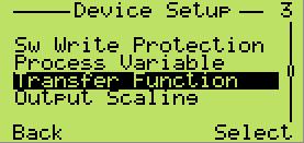


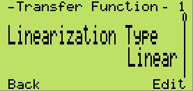
76 76 OI/266/PB-EN Rev. D 2600T Series Pressure transmitters Appendix C HMI structure


77 Appendix C HMI structure 2600T Series Pressure transmitters OI/266/PB-EN Rev. D 77


78 78 OI/266/PB-EN Rev. D 2600T Series Pressure transmitters Appendix C HMI structure


79 Appendix C HMI structure Display 2600T Series Pressure transmitters OI/266/PB-EN Rev. D 79
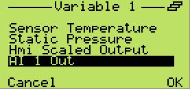
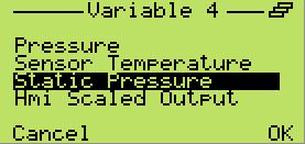

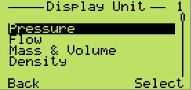
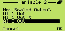
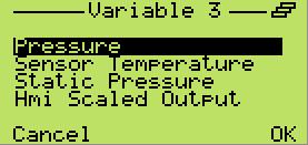
80 80 OI/266/PB-EN Rev. D 2600T Series Pressure transmitters Appendix C HMI structure
81 Appendix C HMI structure 2600T Series Pressure transmitters OI/266/PB-EN Rev. D 81


82 82 OI/266/PB-EN Rev. D 2600T Series Pressure transmitters Appendix C HMI structure


83 Appendix C HMI structure Calibrate 2600T Series Pressure transmitters OI/266/PB-EN Rev. D 83


84 Appendix C HMI structure Diagnostics 84 OI/266/PB-EN Rev. D 2600T Series Pressure transmitters

85 Appendix C HMI structure 2600T Series Pressure transmitters OI/266/PB-EN Rev. D 85


86 Appendix C HMI structure Device info 86 OI/266/PB-EN Rev. D 2600T Series Pressure transmitters


87 Appendix C HMI structure Communication 2600T Series Pressure transmitters OI/266/PB-EN Rev. D 87
88 Appendix D Troubleshooting Appendix D Troubleshooting sym Error HMI code Description Possible Cause Suggested Actions Electronics errors Memory Failure F Electronic Interface error. M Non-Volatile memory burn error M Missing Primary Signal Sensor Invalid F Invalid Sensor Sensor Memory Fail F P-dP Sensor Fail F Static Pressure Sensor Fail F Sensor Temperature Fail F Non-Volatile memory burn error M PdP simulation Input Simulation Active Static Pressure C simulation Sensor Temp simulation The device data loaded at the start up are corrupted Electronic memory corrupted The electronics must be replaced precluding the correct functionality of the device Exchange of data between Electronics and Sensor have problems The device continue to work without problems but at the next power cycle the new configuration will be lost Pressure Sensor errors The primary signal of the sensor is no longer available. The transducer is not in a condition to generate a valid signal. Sensor and/or the connected electronics are incompatible The data in the sensor memory are corrupted precluding the correct functionality of the device The sensor signal value is incorrect due to a mechanical failure The sensor signal value is incorrect due to a mechanical failure Valid only for Differential pressure models The measurement accuracy is decreased more than the acceptable error The device continue to work without problems but any replacement operation is compromised because the back-up configuration is not updated Installation/start-up errors The Process Value is simulated to became the P-dP value measured in input The Process Value is simulated to became the Static Pressure value measured in input The Sensor Temperature Value is simulated to became the measured Sensor Temperature value Exchange of non-critical data between sensor and electronics is precluded due to problem in the electronic circuit or in receiver circuit of the sensor Writings to the electronic non-volatile Memory was not successful The sensor signal is not being updated correctly as a result of an electronics failure, sensor error or a poorly connected sensor cable. The sensor model/version is not longer compatible with the connected electronic version Power the device and retry the operation, if the error persist the electronics should be replaced as soon as possible. The electronics should be replaced as soon as possible. Check cable connection, check sensor and if problem persists, the sensor must be replaced. The sensor must be replaced Sensor memory corrupted The Sensor must be replaced Mechanical damage to the sensor. Loss of fill fluid; The Sensor must be replaced ruptured diaphragm, broken sensor. The circuitry for the sampling of the static pressure The Sensor must be replaced has failed. The circuitry for the sampling of the temperature The Sensor must be replaced has failed. Writings to the Sensor non-volatile Memory was not successful The Sensor should be replaced as soon as possible. The P-dP Value in output is calculated from a value simulated in input Use a HART configurator (DTM - Hand The Static Pressure Value in output is calculated from a value simulated in input The Sensor Temperature Value in output is calculated from a value simulated in input held) to place device back into normal operating mode (Remove the input simulation) 88 OI/266/PB-EN Rev. D 2600T Series Pressure transmitters
89 Appendix D Troubleshooting sym Error HMI code Description Possible Cause Suggested Actions Installation/start-up errors The replacement operation must be executed: - Move the SW 1 of the electronics in position 1 = Replace required Data directions valid Replace Replace Info M required FE to CB not applicable Replace enabled FE to CB not applicable The Replace operation is required after the changing of the electronics or of the sensor The Replace operation is required after the changing of the electronics or of the sensor The Replace operation has been attempted but with wrong direction Pressure Overrange F An overpressure has been detected The measured Process Pressure P-dP Out Of Limit F Static Pressure Out Of Limit F Sensor Temperature Out Of S Limit Max. Working Pressure M Exceeded value is outside the sensor limits and no longer representing the true applied process value. The measured Static pressure is above its operational limit The measured sensor temperature is outside of its operational limits The Static Pressure is higher than the acceptable mechanical limit for the process connection elements. The Electronics or the Sensor have been changed but the replacement operation has not been executed The Electronics or the Sensor has been changed and a replacement operation for a new sensor has to be executed. The Electronics or the Sensor have been changed, The replacement has been enabled but with a wrong direction (SW 2 = 0) Process errors This effect could be produced by other equipment on the process, (valves..). Exceeding the pressure range can cause reduced accuracy or mechanical damage to the diaphragm material and may require calibration/replacement. The measurement range has not been correctly calculated OR an incorrect transducer model has been selected. The static pressure of the process exceeds the limit of the sensor. Exceeding the Static Pressure can reduce accuracy, mechanically damage the diaphragm and may require calibration/replacement. An incorrect transducer model could have been selected. The temperature of the process environment affects the pressure transmitter; Excess temperature can reduce accuracy, degrade device components and may require calibration/replacement. The static pressure of the process exceeds the MWP supported by the transmitter. Exceeding the MWP can mechanically damage the process connections (flanges, pipes.) and/or be dangerous Enable replace mode -Select the SW 2 the element that has been changed between new Sensor or new electronics - Power Cycle the device - Move the SW 1 of the electronics in position 0 The replacement operation must be executed: Only electronics data can be copied into the sensor - Move the SW 1 to Enable replace mode (1) - Select with the SW 2 to New Sensor (1) - Power Cycle the device - Move the SW 1 to Disable replace mode (0) Change the replacement direction (if possible) - The SW 1 is already set to Enable replace mode (1) - Select with the SW 2 to New Sensor (1) - Power Cycle the device - Move the SW 1 to Disable replace mode (0) The compatibility of pressure transmitter model and process conditions has to be checked. A different transmitter type could be required The compatibility of pressure transmitter model and process conditions has to be checked. Probably a different transmitter type is required. The compatibility of pressure transmitter model and process conditions has to be checked. Probably a different transmitter type is required. The compatibility of pressure transmitter model and process conditions has to be checked. A different installation type could be required e.g. remote seals. The compatibility of process connections and material with the process has to be checked. A different installation type could be required e.g. remote seals. 2600T Series Pressure transmitters OI/266/PB-EN Rev. D 89
90 sym Error HMI code Description Possible Cause Suggested Actions Primary Variable Out of Range S Process value is outside its working range The measured pressure value is beyond its Low or High scaling limits Static Pressure Out of Range S Static Pressure is outside its working range The Measured Static Pressure is beyond its Low or high scaling limits Both Impulse Lines Plugged Impulse Line on High Side Plugged PILD Output M Impulse Line on Low Side Plugged One Undefined impulse line plugged PILD Changed Operating Conditions M PILD algorithm has detected both impulse lines plugged. PILD algorithm has detected a plugged impulse line on the HIGH side. PILD algorithm has detected a plugged impulse line on the LOW side. PILD algorithm has detected one plugged impulse line. The pressure value currently detected is too different from what used for the PILD Training Both connections between the pressure sensor and the process are blocked either by plugging or closed valves. The connection between the pressure sensor and the process on the HIGH side is blocked either by plugging or closed valves. The connection between the pressure sensor and the process on the LOW side is blocked either by plugging or closed valves One of the connections between the pressure sensor and the process is blocked either by plugging or closed valves. Process conditions have changed to an extent that new settings for the PILD algorithm are needed. Adjust the working range if possible. Adjust the working range if possible. Check valves and impulse line. Clean impulse line if necessary and initiate PILD training A new Training is necessary for this new process condition
91 ABB WARRANTY REPAIR TROUBLE SHEET REPAIR ORDER Rejection or discrepancy Reports copy attached not available IDENTIFICATION Customer Purchase order No Plant Name of person to contact Instrument Tag No Model Serial Number OPERATING CONDITIONS Specify location, environmental conditions, type of service and approximate number of operating hours or date of installation if known REASON FOR RETURN DANGEROUS FLUIDS In case of toxic or otherwise dangerous fluid, please attach the relevant Material Safety Data Sheet Trouble found during. Installation Commissioning Maintenance At start up On service Shipping information for the return of the equipment Material returned for factory repair should be sent to the nearest ABB Service Center; transportation charges prepaid by the Purchaser Please enclose this sheet duty completed to cover letter and packing list Date Signature Originator ABB S.p.A Process Automation Division Sales Office: Via Statale, Lenno (CO) Italy Tel Fax
92 ABB RETURN REPORT No.: *) Please always fill in. Otherwise the case will not be handled as return CONTROL OF SUBSTANCES HAZARDOUS TO HEALTH (C.O.S.H.H.) Decontamination declaration - EQUIPMENT RETURNED FOR REPAIR, CALIBRATION OR CREDIT From Description Return authorization no. Model number Serial number A) The above equipment has not been in contact with any material which is hazardous to health. B) The above equipment has been in contact with the material(s) noted below but that it has now been completely de-contaminated and is now safe to handle and dismantle without any special precautions. Material(s) which have been in contact with this equipment: C) If A) or B) are not applicable full instructions for the safe handling of this equipment for disposal must be supplied. Please delete A), B) or C) above as applicable, complete the signature section below, then send the completed declaration either with the returned items, or by fax for the attention of the Calibration & Repair Centre.. Note no action to examine or repair equipment will be undertaken until a valid COSHH declaration has been received, completed by an authorized officer of the end user company. Signed Name Position Date ABB S.p.A Process Automation Division Uffici Commerciali / Sales Office: Via Statale, Lenno (CO) Italy Tel Fax abb.instrumentation@it.abb.com
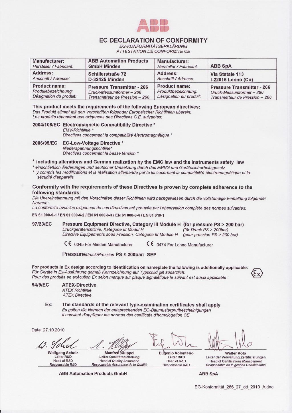
93
Operating Instruction OI/266/HART-EN Rev. G. 2600T Series Pressure Transmitters 266 Models HART. Engineered solutions for all applications
 Operating Instruction OI/266/HART-EN Rev. G 2600T Series Pressure Transmitters 266 Models HART Engineered solutions for all applications The Company We are an established world force in the design and
Operating Instruction OI/266/FF-EN Rev. B
 Operating Instruction OI/266/FF-EN Rev. B 2600T Series Pressure Transmitters 266 Models FOUNDATION Fieldbus Engineered solutions for all applications The Company We are an established world force in the
2600T Series Pressure Transmitter Models 264DC Differential and 264HC Gage Level Transmitters. Kent-Taylor
 INDUSTRIAL INSTRUMENTS AND CONTROLS SPECIALIST Kent-Taylor 2600T Series Pressure Transmitter Models 264DC Differential and 264HC Gage Level Transmitters Features Include Base accuracy : ±0.075% Span limits
OPTIBAR P 1010 C Technical Datasheet
 Technical Datasheet Pressure transmitter with recessed diaphragm for general applications Wide variety thanks to modular design Measuring ranges up to 250 bar / 3750 psi High overload and temperature stability
User s Manual EJX/EJA-E Series NEPSI Certification [Option code: /NF2, /NS21, /NS24 and /NS25] IM 01C25A00-12E
![User s Manual EJX/EJA-E Series NEPSI Certification [Option code: /NF2, /NS21, /NS24 and /NS25] IM 01C25A00-12E](/thumbs/86/93658860.jpg "User s Manual EJX/EJA-E Series NEPSI Certification [Option code: /NF2, /NS21, /NS24 and /NS25] IM 01C25A00-12E") User s Manual EJX/EJA-E Series NEPSI Certification [Option code: /NF2, /NS21, /NS24 and /NS25] 12th Edition 1 1. Introduction Thank you for purchasing the DPharp electronic pressure transmitter. This manual
User s Manual EJX/EJA-E Series NEPSI Certification [Option code: /NF2, /NS21, /NS24 and /NS25] 12th Edition 1 1. Introduction Thank you for purchasing the DPharp electronic pressure transmitter. This manual
Magnetic level switch type MR783 Instruction Manual
 Magnetic level switch Magnetic level switch type MR783 1. DESCRIPTION page 3 1.1 Operation page 3 1.2 Application page 3 1.3 Description page 3 2. SPECIFICATIONS page 3 2.1 Service Conditions page 4 2.2
Measurement accessories METPOINT OCV for the measurement in systems up to 40 bar
 EN - english Instructions for installation and operation Measurement accessories METPOINT OCV for the measurement in systems up to 40 bar Dear customer, Thank you for deciding in favour of the METPOINT
VG5 Supplementary instructions
 VG5 Supplementary instructions 2-wire / 10 GHz Radar (FMCW) Level Meter Supplementary Instructions for ATEX applications HYCONTROL CONTENTS VG5 1 General safety information 4 1.1 Scope of the document...
DK46 - DK800 Supplementary instructions
 DK46 - DK800 Supplementary instructions Variable area flowmeter Device category II2G with electrical internals Additional Ex manual KROHNE CONTENTS DK46 - DK800 1 Safety instructions 3 1.1 General... 3
Field IT 2600T Series Pressure Transmitters
 Instruction for installation and commissioning PED/262_4H_9 Field IT 2600T Series Pressure Transmitters Models 264H/N/G/A - 1 - ABB The Company We are an established world force in the design and manufacture
* * Data Sheet and Operating Manual. Digital manometer ME01 ## # 87 # HL S#### Dust explosion protection Zone 22.
 *09005087* DB_BA_EN_ME01_S Rev.A 12/16 *09005087* d e v e l o p i n g s o l u t i o n s Data Sheet and Operating Manual ME01 Digital manometer Table of Contents ME01 ## # 87 # HL S#### Dust explosion protection
Mounting and Operating Instructions EB 2558 EN. Self-operated Pressure Regulators. Type Pressure Build-up Regulator
 Self-operated Pressure Regulators Type 2357-31 Pressure Build-up Regulator with safety function and integrated excess pressure valve Type 2357-31 with non-return unit at port C Ports A and B with soldering
PX3005. Rangeable Industrial Pressure Transmitter M-5721/1018
 PX3005 Rangeable Industrial Pressure Transmitter INTRUCTION HEET -5721/1018 hop online at omega.com e-mail: info@omega.com For latest product manuals: omegamanual.info ! Pressure / differential pressure
Torque Tube TB300 Digital Transmitters
 Page 1 of 7 7E.300-E Issue 4-2009 Description Series TB300 torque tube liquid level instruments utilize the buoyancy exerted on a displacer when immersed in a liquid. The buoyancy on the displacer is proportional
Operating Instructions
 Operating Instructions Ex d Enclosures in Light Metal / Flameproof Encapsulation > 8265/0 Empty Enclosure > 8265/4 controller, installed in Ex e enclosure > 8265/5 controller Contents 1 Contents 1 Contents...2
L3 Pressure and Level transmitter
 SENSORS FOR AND BIOPHARMA. Product Information L3 L3 Pressure and Level transmitter Range of applications Hydrostatic Level measurement in dynamic temperature environments Pressure measurement in pipes
Instruction Manual Contact Pressure Vacuum Gauge
 MS10 Instruction Manual Contact Pressure Vacuum Gauge Table of Contents 1. Safety Instructions 2. Intended Applications 3. Product Description and Functions 4. Installation 5. Commissioning 6. Maintenance
Differential Pressure Transmiter
 Differential Pressure Transmiter Description The is an economical alternative to established differential pressure transmitters. It combines state of the art electronics and a high performance sensor;
Operating Instructions
 Operating Instructions Light-metal Ex d enclosures / flameproof enclosure > 8265/0 Empty enclosure > 8265/4 Control panel, integrated in Ex e enclosure > 8265/5 Control panel Table of Contents 1 Table
Type N-10, N-11 Hazardous Area Non-incendive Transmitters
 Electronic Pressure Catalog > Hazardous Area > N-10, N-11 Type N-10, N-11 Hazardous Area Non-incendive Transmitters Applications Natural gas compressors Wellhead monitoring Pipeline pressure General industrial
Instruction Manual Differential Pressure Transmitter
 DE13 Instruction Manual Differential Pressure Transmitter Table of Contents 1. Safety Instructions 2. Intended Applications 3. Product Description and Functions 4. Installation 5. Commissioning 6. Maintenance
How to specify a product. Process Sensors and Mechanical Instruments
 How to specify a product Process Sensors and Mechanical Instruments Keep the overview. Here is some guideline information on how to specify our products. Intended as supplementary help to specification
Pressure Measurement Single-range transmitters for general applications
 Siemens A 207 Overview Application The SITRANS P Compact pressure transmitter is designed for the special requirements of the food, pharmaceutical and biotechnology industries. The use of high-grade materials
IDL01. Battery Powered Precision Digital Gauge for Leak Testing. Stainless Steel Sensor. class 0.05
 IDL0 Battery Powered Precision Digital Gauge for Leak Testing Stainless Steel Sensor class 0.05 Nominal pressure from 0 00 mbar up to 0... 00 bar Special characteristics modular sensor concept data logger
Type 3709 Pneumatic Lock-up Valve. Translation of original instructions. Mounting and Operating Instructions EB 8391 EN
 Type 3709 Pneumatic Lock-up Valve Translation of original instructions Mounting and Operating Instructions EB 8391 EN Edition July 2017 Note on these mounting and operating instructions These mounting
Installation and Operation Manual
 Installation and Operation Manual WIKA FLR-SBDF / BLR-SBDF Magnetic Level Transmitter (Please retain for future usage) Contact: Gayesco-WIKA USA, L.P. 229 Beltway Green Boulevard Pasadena, TX 77503 www.wika.com
AMT-Ex Dewpoint Transmitter
 AMT-Ex Dewpoint Transmitter Instruction Manual Alpha Moisture Systems Alpha House 96 City Road Bradford BD8 8ES England Tel: +44 1274 733100 Fax: +44 1274 733200 email: mail@amsytems.co.uk web: www.amsystems.co.uk
Mounting and Operating Instructions EB 3007 EN. Self-operated Pressure Regulators. Differential Pressure Regulators (opening) Type Type 42-25
 Type Type 42-25") Self-operated Pressure Regulators Differential Pressure Regulators (opening) Type 42-20 Type 42-25 Type 42-20 Differential Pressure Regulator Type 42-25 Differential Pressure Regulator Mounting and Operating
Self-operated Pressure Regulators Differential Pressure Regulators (opening) Type 42-20 Type 42-25 Type 42-20 Differential Pressure Regulator Type 42-25 Differential Pressure Regulator Mounting and Operating
Siemens AG psi (6 bar) 145 psi (10 bar) 464 psi (32 bar) 1450 psi (100 bar) 3626 psi (250 bar) 8700 psi (600 bar) psi (800 bar)
 145 psi (10 bar) 464 psi (32 bar) 1450 psi (100 bar) 3626 psi (250 bar) 8700 psi (600 bar) psi (800 bar)") Technical specifications SITRANS P, DS III series Input Measured variable Spans (infinitely adjustable) or nominal measuring range and max. permissible test pressure HART Gauge pressure Span (min.... max.)
Technical specifications SITRANS P, DS III series Input Measured variable Spans (infinitely adjustable) or nominal measuring range and max. permissible test pressure HART Gauge pressure Span (min.... max.)
PULSAR 5000 SERIES OPERATING & INSTALLATION INSTRUCTIONS SERIES 5000 PLEASE READ CAREFULLY BEFORE INSTALLING
 PULSAR 5000 SERIES OPERATING & INSTALLATION INSTRUCTIONS SERIES 5000 PLEASE READ CAREFULLY BEFORE INSTALLING Please Note: Ranges above 500mbar are designed and manufactured in accordance with sound engineering
Certificate of Conformity
 Certificate Holder: ABB Automation Products GmbH Schillerstrasse 72 D-32425 Minden GERMANY Electrical Apparatus: Type of Protection: 2600T Pressure Transmitter Models 265../267../269.. Communication protocols:
Model PDT Dewpoint Transmitter
 Model PDT Dewpoint Transmitter Instruction Manual Alpha Moisture Systems Alpha House 96 City Road Bradford BD8 8ES England Tel: +44 1274 733100 Fax: +44 1274 733200 email: mail@amsytems.co.uk web: www.amsystems.co.uk
Declaration of Conformity as per Directive 97/23/EC
 Declaration of Conformity as per Directive 97/23/EC The manufacturer declares that:, 47906 Kempen, Germany Multi-way diverting valves Series 29a and Series 29b, with packing with lever 1. The valves are
1 Overview. Pressure Measurement Transmitters for basic requirements. 1/16 Siemens FI SITRANS P220 for gauge pressure
 Siemens AG 204 Overview The pressure transmitter SITRANS P220 measures the gauge pressure of liquids, gases and vapors. Stainless steel measuring cell, fully welded Measuring ranges 2.5 to 600 bar (36.3
Electro-Pneumatic Converter YT-940 SERIES
 Electro-Pneumatic Converter YT-940 SERIES PRODUCT MANUAL VERSION 1.00 Contents 1. Introduction 3 1.1 General information for the users. 3 1.2 Manufacturer Warranty 3 1.3 Explosion Proof Warning. 4 2. Product
Flowmeter. Original operating manual DFM
 Flowmeter Original operating manual Series DFM 165 350 Version BA-2016.08.09 EN Print-No. 300 458 TR MA DE Rev002 ASV Stübbe GmbH & Co. KG Hollwieser Straße 5 32602 Vlotho Germany Phone: +49 (0) 5733-799-0
Compact differential pressure switch Flameproof enclosure Ex d Models DE, DEC
 Mechatronic pressure measurement Compact differential pressure switch Flameproof enclosure Ex d Models DE, DEC WIKA data sheet PV 35.41 Process Compact Series Applications Differential pressure monitoring
Target disk flowmeter Series DP. Instructions manual DP65 DP500. R-MI-DP Rev.: 4 English version
 Target disk flowmeter Series DP Instructions manual DP65 DP500 R-MI-DP Rev.: 4 English version PREFACE Thank you for choosing the flowmeter series DP from Tecfluid S.A. This instruction manual allows the
Differential Pressure Transmitters
 No. SS2-GTX00D-0500 (Rev.3) AT9000 Advanced Transmitter Differential Pressure Transmitters OVERVIEW AT9000 Advanced Transmitter is a microprocessor-based smart transmitter that features high performance
2600T Series Safety Pressure Transmitters
 Instruction for installation and commissioning PED/268H_2 2600T Series Safety Pressure Transmitters Models 268H/N - 1 - ABB The Company We are an established world force in the design and manufacture of
Pneumatic proportional controller Types M Types FM Function tested for use of the float in Ex-zone 0
 Operating Manual LTIA5E Pneumatic proportional controller Types M Types FM Function tested for use of the float in Ex-zone 0 Contents 1. Safety Instructions 2. Conformity to standards 3. Technical data
GI Series Diaphragm Pressure Gauge Guard
 Diaphragm Pressure Gauge Guard INSTRUCTION MANUAL Please read this Instruction Manual Carefully and Thoroughly for the Correct and Optimum use of this Product. Kindly keep this manual in a convenient place
Steam Trap BK 15 (DN40, DN 50) Original Installation Instructions English
 Original Installation Instructions English") Steam Trap BK 15 (DN40, DN 50) EN English Original Installation Instructions 810682-03 1 Contents Page Important Notes Usage for the intended purpose... 4 Safety note... 4 Danger... 4 Attention... 4 Application
Steam Trap BK 15 (DN40, DN 50) EN English Original Installation Instructions 810682-03 1 Contents Page Important Notes Usage for the intended purpose... 4 Safety note... 4 Danger... 4 Attention... 4 Application
GEMS SENSORS & CONTROLS
 GEMS SENSORS & CONTROLS OPERATING & INSTALLATION INSTRUCTIONS 31XX / 32XX SERIES PLEASE READ CAREFULLY BEFORE INSTALLING Part Number: 560550-0076 Issue: E INTRODUCTION Series 3100/3200 high output pressure
Operating Instructions. Ball valve fitting according to ZB For pressure transmitter VEGABAR 82. Document ID: 50027
 Operating Instructions Ball valve fitting according to ZB 2553 For pressure transmitter VEGABAR 82 Document ID: 50027 Contents Contents 1 About this document 1.1 Function... 3 1.2 Target group... 3 1.3
OFFICINE OROBICHE S.p.A. 1/9
 OFFICINE OROBICHE S.p.A. 1/9 INSTRUCTIONS MANUAL FOR LEVEL SWITCHES SERIES 7000 mod. 7250 AND 7400 Electric 1. INSTRUMENT DESCRIPTION Series 7000 level switches have been designed for external lateral
TYPE APPROVAL CERTIFICATE
 TYPE APPROVAL CERTIFICATE Certificate No: TAA0000123 This is to certify: That the Pressure Transmitter with type designation(s) SITRANS P series DS III, P310, P410 Issued to Siemens AG - Process Industries
Instruction Manual Differential Pressure Transmitter
 DE61 Instruction Manual Differential Pressure Transmitter Table of Contents 1. Safety Instructions 2. Intended Applications 3. Product Description and Functions 4. Installation 5. Commissioning 6. Maintenance
Installation & Operation Manual Proven Quality since 1892
 Content 1. ERIKS operating companies 2. Product description 3. Requirements for maintenance staff 4. Transport and storage 5. Function 6. Application 7. Installation 8. Maintenance 9. Service and repair
GM Series Dual-Block Multi-Function Gas Control Valves
 Installation Sheets Manual 121 Gas Combustion Combination Controls and Systems Section G Technical Bulletin GM Issue Date 0297 GM Series Dual-Block Multi-Function Gas Control Valves Figure 1: GM Series
P9000 DESCRIPTION. For parts requiring RoHS compliance, please contact factory. P February /6
 P9000 High accuracy through digital compensation High thermal stability Rugged stainless steel construction Ideal for test stands High burst pressure limit DESCRIPTION The P9000 Series is a range of advanced,
SITRANS P measuring instruments for pressure
 SITRANS P measuring instruments for pressure Z series for gage pressure Siemens AG 008 Overview Design The main components of the pressure transmitter are: Brass housing with silicon measuring cell and
OSAT Series. Intrinsically Safe Infrared Temperature Sensor Operator's Guide
 OSAT Series Intrinsically Safe Infrared Temperature Sensor Operator's Guide Issue L Jan 2017 Introduction OSAT Series intrinsically safe non-contact infrared temperature sensors measure the temperature
INSTALLATION & MAINTENANCE INSTRUCTIONS
 DESCRIPTION / IDENTIFICATION The QBX series valve uses Proportion-Air closed loop technology for Pressure control. It gives an output pressure proportional to an electrical command signal input. The QB1X
Safety Instructions Liquiphant FailSafe FTL80, FTL81, FTL85
 XA01537F-A/00/EN/01.16 71333275 Products Solutions Services Safety Instructions Liquiphant FailSafe FTL80, FTL81, FTL85 0Ex ia IIC T6 Ga X Ga/Gb Ex ia IIC T6 X Document: XA01537F-A Safety instructions
DM01. Please visit our website: Battery Powered Precision Digital Gauge. Stainless Steel Sensor. class 0.05
 DM0 Battery Powered Stainless Steel Sensor class 0.05 Nominal pressure from 0 00 mbar up to 0... 00 bar Special characteristics modular sensor concept data logger graphic display stainless steel housing
English. Introduction. Safety Instructions. All Products. Inspection and Maintenance Schedules. Parts Ordering. Specifications WARNING WARNING
 Contents All Products... Gb-1 Control Valves... Gb-2 Control Valve Actuators... Gb-3 Regulators... Gb-3 Relief Valves... Gb-4 Instruments, Switches, and Accessories... Gb-4 Products Covered by Battery
Further technical information is available on
 1 of 5 Manufacture address : Bartec Technor AS Dusavikveien 39 4007 Stavanger Norway Further technical information is available on www.bartec-technor.no Note on instructions When working in hazardous areas,
I/P Transducer Positioner Module
 I/P Transducer Positioner Module VRC P/N: 7958032 Installation, Operation and Maintenance Instructions 2.09 [53.1] 1.30 [32.9] 2.97 [75.5] 0.78 [19.8] 0.18 [4.4] 1.42 [36.1] n.18 MOUNTING HOLES (2) PLACES
Pressure relief valve
 Pressure relief valve Operating manual Series DHV 712 R Version BA-2016.01.19 EN Print-No. 300 472 TR MA DE Rev001 ASV Stübbe GmbH & Co. KG Hollwieser Straße 5 32602 Vlotho Germany Phone: +49 (0) 5733-799-0
Electropneumatic Positioner and Pneumatic Positioner Type 3760 JIS
 Electropneumatic Positioner and Pneumatic Positioner Type 3760 Application Single-acting positioners for direct attachment to pneumatic control valves. Supplied with an electric input signal of 4 to 20
Pressure Switches Application Guideline
 Pressure Switches Application Guideline Product Overview The Fema Pressure Switch product portfolio provides devices suitable for many applications. The portfolio contains Special functions and equipment
Installation, operating and maintenance Instructions for Seemag bypass level indicator
 Issue: S Date: 05-09-14 Type G35 General information The Seetru bypass magnetic level indicator, abbreviate SEEMAG, serves to show the filling level of fluids in tanks, basins, tubes etc. The Seemag operates
Instruction Manual AD 1000 / BA 1000 Absolute Pressure Sensor
 Instruction Manual AD 1000 / BA 1000 Absolute Pressure Sensor halstrup-walcher GmbH Stegener Straße 10 D-79199 Kirchzarten Phone: +49 (0) 76 61/39 63 0 Fax: +49 (0) 76 61/39 63 99 E-Mail: info@halstrup-walcher.com
Climatic Independent Level Sensor LAR
 1 Product Information LAR-361 LAR-761 Climatic Independent Level Sensor LAR Application / Specified usage Authorizations Hydrostatic level measurement in humid ambiance Special applicable for exterior
Differential Pressure Transmitters
 No. SS2-GTX00D-00 AT9000 Advanced Transmitter Differential Pressure Transmitters OVERVIEW AT9000 Advanced Transmitter is a microprocessor-based smart transmitter that features high performance and excellent
DK48 - DK800. Quick Start. Variable area flowmeter
 Quick Start Variable area flowmeter General safety notes You can find the newest and/or additional information in the handbook, the datasheet, special manuals, certificates and the download center at www.krohne.com.
Pressure Measurement Single-range transmitters for general applications
 Siemens AG 07 Overview Function U const. p U I EM Sensor Connection for auxiliary power supply Vent pipe with humidity filter Protective conductor connection/ Equipotential bonding Diaphragm The pressure
FPD175 Compact orifice carrier assembly
 ABB MEASUREMENT & ANALYTICS OPERATING INSTRUCTION FPD175 Compact orifice carrier assembly The smart solution for remote applications. Measurement made easy Installation, commissioning and operating / maintenance
L (up to 25 m) Electronic part. working temp.: Ñ IP 66 / IP67. Mounting bracket ÐÑ. Sensor type. working temp.:
 Electronic part. working temp.: Ñ IP 66 / IP67. Mounting bracket ÐÑ. Sensor type. working temp.:") Smart level probe type APC-2000ALW/L Programmable zero shift, range and damping ratio 4...20 ma output signal + HART protocol Accuracy 0,16% Local display Intrinsic safety certificate (ATEX, IECEx) II
Smart level probe type APC-2000ALW/L Programmable zero shift, range and damping ratio 4...20 ma output signal + HART protocol Accuracy 0,16% Local display Intrinsic safety certificate (ATEX, IECEx) II
Hydrostatic. Continuous level measurement. Overview Page 188 VEGAWELL 52 Page 190 VEGABAR 86, 87 Page 192 Accessory Page 196 AL-EN
 Hydrostatic Continuous level measurement 8 Overview Page 188 VEGAWELL 52 Page 190 VEGABAR 86, 87 Page 192 Accessory Page 196 187 Hydrostatic Level and pressure measurement Measuring principle The pressure
High-performance submersible pressure transmitter For level measurement Model LH-10
 Electronic pressure measurement High-performance submersible pressure transmitter For level measurement Model LH-10 WIKA data sheet PE 81.09 Applications Level measurement in rivers and lakes Deep well
The Discussion of this exercise covers the following points:
 Exercise 5-3 Wet Reference Leg EXERCISE OBJECTIVE Learn to measure the level in a vessel using a wet reference leg. DISCUSSION OUTLINE The Discussion of this exercise covers the following points: Measuring
Model 266MST Differential Model 266RST Absolute. 2600T Series Pressure Transmitters Engineered solutions for all applications
 Data Sheet DS/266MST/RST-EN Model 266MST Differential Model 266RST Absolute 2600T Series Pressure Transmitters Engineered solutions for all applications Base accuracy 0.04 % of calibrated span, (Option
Pressure Automated Calibration Equipment
 GE Measurement & control Pressure Automated Calibration Equipment Safety Instructions and User Guide - K0447 PACE5000 PACE6000 K0447 Issue No. 9 1 10 1 PACE5000 1 2 3 4 5 PACE6000 2 6 7 8 3 4 5 6 7 8 9
S26 remote and direct mount seals Diaphragm seals for 266 pressure transmitters
 ABB MEASUREMENT & ANALYTICS OPERATING INSTRUCTION S26 remote and direct mount seals Diaphragm seals for 266 pressure transmitters Engineered solutions for all applications Measurement made easy 266DRH
ABB measurement & analytics data sheet. 266MST and 266RST Differential and absolute pressure transmitters
 ABB measurement & analytics data sheet 266MST and 266RST Differential and absolute pressure transmitters 2 266MST an d 266RST Di ffer en ti al And absolu te pre ssu re tr ansmit te rs DS/266MST/RST-EN
VS18/26 with PROFINET and EtherNet/IP Interface. ATEX Installation Instructions
 VS18/26 with PROFINET and EtherNet/IP Interface ATEX Installation Instructions INDEX 1. INTENDED USAGE 3 2. OPERATING MANUAL ATEX 4 2.1 General conditions 4 2.2 Installation 5 2.3 Operating 5 2.4 Failures
SITRANS. Pressure transmitter SITRANS P, Z series for gauge and absolute pressure. Introduction. Safety instructions 2.
 Introduction 1 Safety instructions 2 SITRANS Pressure transmitter SITRANS P, Z series for gauge and absolute pressure 7MF1564 Description 3 Assembly and connection 4 Technical data 5 Dimensional drawings
Certificate of Compliance
 Certificate of Compliance Certificate: 2419437 Master Contract: 203012 Issued to: ABB Automation Products GmbH 72 Schillerstrasse Minden, 32425 Germany Attention: Ralf Schaffer The products listed below
RTX 1000H Series. Versatile Transmitters for a World of Pressure. GE Measurement & Control. Features
 GE Measurement & Control RTX 1000H Series Versatile Transmitters for a World of Pressure GE Measurement & Control is renowned for the design and manufacture of compact and rugged high performance pressure
1 Overview. Pressure Measurement Single-range transmitters for general applications. 1/22 Siemens FI US Edition
 Siemens AG 07 SITRANS LH00 Transmitter for hydrostatic level Overview Function U const. p U I EM The pressure transmitter SITRANS LH00 is a submersible sensor for hydrostatic level measurement. The pressure
Installation and Maintenance Instruction Manual
 Installation and Maintenance Instruction Manual Differential pressure gauge, model F5503 and F5503-HP for industrial application in the following configuration: ###F5503### differential pressure gauge
Supplementary Operator s Manual 42/24-14 EN Rev. 3
 Advance Optima Continuous Gas Analyzers AO2000 Series with Uras26, Magnos206, Caldos25, Caldos27 Designed per Category 3G for Measurement of Flammable Gases ( Safety Concept ) and Non-flammable Gases Supplementary
FTS SUBMERSIBLE PRESSURE TRANSMITTER USER S MANUAL
 FTS SUBMERSIBLE PRESSURE TRANSMITTER USER S MANUAL TABLE OF CONTENTS PRODUCT OVERVIEW 2 I - USE AND CARE: 3 II - INSTALLATION: 5 III - GENERAL MAINTENANCE TIPS: 5 IV - APPENDIX: A-1 2-WIRE CURRENT LOOP
Installation and Maintenance Instruction Manual
 Installation and Maintenance Instruction Manual Bi-metal Thermometer Model A and E in a configuration - pursuant to ASME B40.200: ##=E#=### or ##=ERT#=### - pursuant to EN 13190: ###=A#=### or ##=ART#=###
ENGLISH SAFETY INSTRUCTIONS FOR PRESSURE TRANSMITTERS MODELS 6X1ED - EE - EH - EG - EA, 622ED, 6X1ES
 ENGLISH SAFETY INSTRUCTIONS FOR PRESSURE TRANSMITTERS MODELS 6X1ED - EE - EH - EG - EA, 622ED, 6X1ES BS EN ISO 9001 R E G IS T E R E D FIR M St Neots, U.K. Cert. No. Q5907 Stonehouse, U.K. Cert. No. FM
AT9000 Advanced Transmitter Differential Pressure Transmitters
 No. SS2-GTX00D-0500 AT9000 Advanced Transmitter Differential Pressure Transmitters OVERVIEW AT9000 Advanced Transmitter is a microprocessor-based smart transmitter that features high performance and excellent
Pressure switch KP-E. Data sheet
 Data sheet Pressure switch KP-E KP-E pressure switches for use in refrigeration and air conditioning systems are equipped with SPDT gold plated contacts and stainless steel bellows. The high pressure switches
Differential pressure
 Differential pressure 9 Overview Page 200 VEGADIF 65 Page 202 Chemical seal Page 204 Accessory Page 208 199 VEGADIF For differential pressure, level and flow measurements Measuring principle The sensor
Instruction Manual BA90 Precision Barometer
 Instruction Manual BA90 Precision Barometer halstrup-walcher GmbH Stegener Straße 10 D-79199 Kirchzarten Germany Phone: +49 (0) 76 61/39 63 0 Fax: +49 (0) 76 61/39 63 99 E-Mail: info@halstrup-walcher.com
Model 106 DPI "Micro-switch" Installation and Operating Instructions
 Mid-West Instrument Model 106 DPI "Micro-switch" Installation and Operating Instructions BULLETIN NO. IM116DPImicro/09A Replaces --- INSPECTION Before installation carefully check the Model Number on each
Pressure relief valve
 Pressure relief valve Operating manual Series DHV 718 Version BA-2016.01.11 EN Print-No. 300 524 TR MA DE Rev001 ASV Stübbe GmbH & Co. KG Hollwieser Straße 5 32602 Vlotho Germany Phone: +49 (0) 5733-799-0
DMK 458. Pressure Transmitter for Marine and Offshore. Ceramic Sensor. accuracy according to IEC 60770: standard: 0.25 % FSO option: 0.
 Pressure Transmitter for Marine and Offshore Ceramic Sensor accuracy according to IEC 60770: standard: 0.5 % FSO option: 0. % FSO Nominal pressure from 0... 40 mbar up to 0... 0 bar Output signals -wire:
Ball valve. Operating instructions for series. Version BA Print-No TR MA DE Rev001
 Ball valve Operating instructions for series Version BA-2016.02.05 Print-No. 300 587 TR MA DE Rev001 We reserve the right to make technical changes. Read carefully before use. Save for future use. ASV
DM01. Battery Powered Precision Digital Gauge. Stainless Steel Sensor. class 0.05
 Battery Powered Stainless Steel Sensor class 0.05 Nominal pressure from 0 00 mbar up to 0... 00 bar Special characteristics modular sensor concept data logger graphic display stainless steel housing Ø
Installation and Maintenance Instructions for F5509/F6509 Differential Pressure Gauges
 Differential pressure gauge, model F5509/F6509 for industrial applications in the following configuration: F5509/F6509 differential pressure gauge without switching contact F5509/F6509 differential pressure
1 Overview. Pressure Measurement Single-range transmitters for general applications. 1/22 Siemens FI
 Siemens AG 06 SITRANS LH00 Transmitter for hydrostatic level Overview Function U const. p U I EM The pressure transmitter SITRANS LH00 is a submersible sensor for hydrostatic level measurement. The pressure
Model 266HSH Gauge Model 266NSH Absolute. 2600T Series Pressure Transmitters Engineered solutions for all applications
 Data Sheet DS/266HSH/NSH-EN Rev.C Model 266HSH Gauge Model 266NSH Absolute 2600T Series Pressure Transmitters Engineered solutions for all applications Base accuracy from 0.06 % of calibrated span (optional
Operating instructions Safety Rope Emergency Stop Switches ZB0052 / ZB0053 ZB0072 / ZB0073
 Operating instructions Safety Rope Emergency Stop Switches UK ZB0052 / ZB0053 ZB0072 / ZB0073 7390878 / 02 03 / 2011 Contents 1 Safety instructions...3 2 Installation / set-up...4 2.1 Applications...4