CHEMICAL TANKER MANUAL CH. 09 MAINTAINENCE OF CARGO EQUIPMENT. Rev. No. 1 Date 15-Apr-16 Page Page 1 of MAINTAINENCE OF CARGO EQUIPMENT
|
|
|
- Bryce O’Neal’
- 6 years ago
- Views:
Transcription
1 Page Page 1 of MAINTAINENCE OF CARGO EQUIPMENT To ensure safe and smooth cargo transfer and tank cleaning operations, cargo handling and tank cleaning equipment must be maintained as per maker s instructions and as per company procedures. Maintenance tasks and Maintenance Intervals of the equipment listed below are detailed in the Planned Maintenance System and interval as stated in sec 9.8 and are to be complied with: 1. Cargo Tanks 2. Cargo Pumps 3. Cargo and Ballast valves 4. Cargo and Ballast lines 5. Cargo Hoses 6. Vent Lines and Vapour lines 7. IG / N2 lines 8. P/V valves 9. Emergency shut downs 10. Vapour locks 11. Fixed and Portable Gauging systems (including UTI tapes) 12. Temperature and Pressure sensors 13. High level and overfill alarms 14. Flame screens 9.2. MAINTENANCE OF CARGO HOSES Cargo hoses are to be properly used and maintained in good condition as per maker s instruction. The cargo hose compatibility chart should be readily available with the Chief Officer in CCR and same is to be referred prior using cargo hose for intended transfer operation. Hoses should be retired in accordance with defined criteria. This guidance also applies to any tanker s cargo hoses used for tanker/shore connections and any other flexible hose connected to tanker or shore cargo systems, for example a jumper hose at the end of a ramp serving a pontoon berth. The owner of the hose should attest that any hose provided is certified, fit for purpose, in good physical condition and have been pressure tested.
2 Page Page 2 of 14 Markings to be made on the cargo lines and hoses: 1. Pressure test date and validity. 2. MAWP pressure of the lines of hoses. 3. Serial number of the hose where applicable. 4. Operating temperature of the hose Custody of Hoses 1. The hose should be cleaned up properly and drained out completely. 2. Store the hose in straight line raised off the ground preferably in a cool dark area. 3. Visually check any damage on inside and outside of the hose. (Displacement of the wire, tear, abrasion and any other abnormal features) 4. Never use hot water above 80 C when water is used for cleaning. 5. When live steam is necessary for cleaning, the hose must be open ended, vertically raised and limited steam should be allowed to pass through the hose to avoid damage to the inner lining. (Never blank the end of hose during cleaning by live steam) 6. After cleaning and draining, the hose should be blinded on both ends Precautions before transfer 1. The cargo hose must be inspected and approved by the cargo surveyor for Cleanliness prior being used for cargo transfer. 2. The cargo hose must be supported at appropriate points with the slings provided. 3. Support the hose near manifold connections. 4. Protect the hose against sharp edge. (e.g. jetty edge, ship s sharp upper structure, etc.) 5. Never allow sharp bends during cargo transfer operations. 6. Never allow hose to droop between ship and jetty/ship Withdrawal before service When the hose shows any of the following deformation, such hose should be immediately condemned, clearly marked and stowed away from other hoses.
3 Page Page 3 of Cutting of outer wire. 2. Leakage from hose body and hose ends (between ferrule and hose shank). 3. Wide range of deformation of outer wire and hose body (kink). 4. Heavy displacement of outer and inner wire. 5. Cuts and tears of outer cover to such extent that inner film appears. In consultation with the hose manufacturer, retirement age should be defined for each hose type to determine when it should be removed from service, irrespective of meeting inspection and testing criteria. The temporary elongations at which smooth bore rubber hose assemblies should be withdrawn from service will vary with the type of hose assembly construction, such that either: a) The temporary elongation, when measured, should not exceed 1.5 times the temporary elongation when the hose assembly was new. For example: Temporary elongation of new hose assembly: 4% Temporary elongation at test: 6% maximum Or b) For hose assemblies where the temporary elongation of a new assembly was 2.5% or less, the temporary elongation at the test should not be more than 2% more than that of the new hose assembly. For example: Temporary elongation of new hose assembly: 1% Temporary elongation of old hose assembly: 3% maximum. Or c) Elongation - If permanent elongation exceeds 2% of the overall length of the hose, the hose should be retired from service


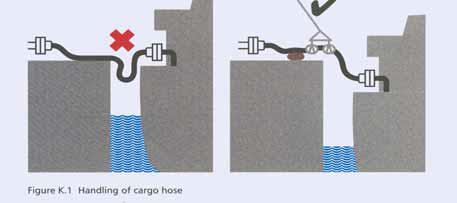
4 Page Page 4 of 14 Handling of Cargo hoses
5 Page Page 5 of TANK CLEANING EQUIPMENT On chemical tankers care & maintenance of tank cleaning equipment is one of the most important aspects of operational maintenance. Equipment that has been properly maintained and cared for will give reliable and trouble free service resulting safe, smooth and efficient tankcleaning operations Tank cleaning Hoses Hoses should be handled with care and kinks and twists should be avoided. 1. Hoses should be clearly marked. 2. The electrical continuity of hoses should be checked regularly and recorded. Defective hoses should be removed from service and discarded. 3. Couplings should be checked and tightened as required Tank cleaning Machine 1. During operations machines should be checked to ensure that they are rotating freely and operating as designed. 2. Check that nozzles are not clogged. 3. Check that there are no loose parts that could drop off and cause a spark. 4. Carry out overhauls as recommended by the maker using appropriate spares. 5. All wear parts should be changed at the recommended intervals High Pressure wash Machine 1. Check that all hoses and connections are in satisfactory condition and that there are no leaks or soft spots. 2. Carry out routine maintenance in accordance with maker s instructions and renew all wear parts at recommended intervals. 3. High pressure wash machines should always be stowed in sheltered area Mucking Machine 1. Check that the wire and hook are in satisfactory condition. If the wire has broken strands then it should be replaced at once.
6 Page Page 6 of Carry out routine maintenance in accordance with maker s instructions and renew all wear parts at recommended intervals. 3. Check the brackets and mountings for any cracks or fatigue Portable Gas freeing fan Check that the impeller is turning smoothly without any wobble or imbalance and that the blades are not touching the sides of the casing. 1. Check that there are no loose parts. 2. Check that all couplings are tight. 3. Check condition of supply and discharge hoses and repair / renew as necessary. 4. Check the condition of vent chutes. These should be free of holes and gashes and the securing arrangements should be in good order PORTABLE SUBMERSIBLE PUMP 1.Check that all hoses and connections are in satisfactory condition and that there are no leaks or soft spots. 2. The flexible hoses are filled with hydraulic oil. Drain off approx. one cup of oil from the hoses before storage (when disconnecting from the main system). Control bend radius for the flexible hoses during storage (min 800 mm). 3. Confirm that the units are safely supported, and check that the snap-on coupling and starting head/flow control valves are greased and protected. 4. Carry out routine maintenance in accordance with maker s instructions and renew all wear parts at recommended intervals. 5. Try out the pump every 3 months, and maintain records in PMS PURGING COFFERDAM Submerged cargo pumps are to be tested for leakage of their mechanical seals and cofferdam with compressed air of suitable pressure as per the maker's instruction (about 2.0kg/cm2). The test is required to identify the amount of hydraulic oil or cargo leaking from the mechanical seals into the cofferdams.
7 Page Page 7 of 14 The test is carried out on the following occasions unless specified otherwise by the pump manufacturer s manual. a. After completion of cargo tank cleaning and before loading b. 1 or 2 days after loading c. Everyday if excessive leakage is detected a) and b) d. Before discharging e. After discharging Results of tests must be recorded in Cargo pump purging log form (CT 14) and submitted to Company. After the leak test, the cofferdams are to be kept pressurized with the tank test air, water etc as specified in the pump manufacturer s manual How to purge the cofferdam 1. Place a suitable container underneath the exhaust trap to collect the leakage. 2. Check that valve and bottom of exhaust trap is not clogged by residue after last purging operation. Stick up with a pin if necessary. 3. Check that the drain hole from the relief valve on the purging valve block is open. Location design of purging valve is different for the various pump types. For technical details, refer to the pumps service manual. 4. Connect air or inert gas supply to the snap-on coupling on the purging valve. 5. Drain the supply line for condensed water Purging Precautions NOTE: To prevent damage from dangerous cargoes, take necessary precautions, wear appropriate PPE and avoid contact with drain from exhaust trap. 1. Open valve on air/inert gas supply line 2. Check that air/inert gas is coming out of the exhaust trap vent line. (Cofferdam is open) 3. The relief valve on the purging valve block is set to an opening pressure of bar, so a small leakage here is normal. 4. Purge cofferdam in several sequences if required. 5. Drain exhaust trap between each sequence. 6. Disconnect air/inert gas supply 7. Close exhaust trap drain valve
8 Page Page 8 of Measure the amount of leakage, -evaluate and log the purging result Evaluation of the purging result CARGO LEAKAGE 1. Cargo in the cofferdam can come from shaft seals, flange face seals in pipe stack/pump head or damage (cracks) on the pipe stack/pump head. 2. A small leakage rate over the shaft seals up to about 0.5 L/day during pump operation is normal, and replacement of seals should not be necessary with this leakage rate. For short periods of time, higher leakage peaks can occur. 3. The leakage rate is also dependant on the type of cargo. Some cargoes like naphta, condensate etc., penetrate the shaft seals more easily than lub. oils, vegetable oils and other viscous cargoes. If the leakage rate is up to about 2 liters/day, the pump must be purged a couple of times daily, and inspected as soon as possible to find the reason for the leakage. 4. Intensify the purging if the leakage rate is increasing above acceptable level. If this is not keeping the leakage under control, close the hydraulic service valve. Do not operate the pump, use the portable pump to discharge the cargo. The development of a cargo leakage can be followed if purging is done according to specified intervals. Thereby maintenance work can be planned, and unexpected shut down due to leakage can be avoided Hydraulic Oil Leakage Hydraulic oil in the cofferdam can come from shaft seals, flange face seals in pipe stack/pump head or damage (cracks) on the pipe stack/pump head. A small leakage rate into the cofferdam up to about 10ml/h (0.25 L/day) from the mechanical oil seal or lip seal during pump operation is normal. For short periods of time, higher leakage peaks can occur How to detect air in the system Cargo Pump will not start from remote Level variations in the hydraulic oil tank at different system pressure. Back flow to hydraulic oil tank during stand still Possible Yes Yes
 during operation.")
9 Foaming in the hydraulic tank Page Page 9 of 14 Yes Oil sample milky /white, or air bubble mixed into the oil Yes Abnormal noise from hydraulic pumps or motors. Possible Uncontrolled pressure variations (hunting) during operation. Possible Pressure peak shock in the system during start/stop of consumer Possible
10 Page Page 10 of The Ten Commandments 1. Purge regularly 2. Dismantle a pump only after identifying the problem. 3. Pressure test the pump, cofferdam and pipe stack using the kit 4. Use genuine spares 5. Use pump performance curves to establish condition of the pump 6. Do not increase system pressure more than 15 bar above the highest consumer requirement. 7. Avoid air (like plague!!) 8. Keep oil clean 9. Send oil samples for analysis regularly and never mix oil grades 10. Implement a planned maintenance system for the entire cargo handling system 9.6. CARGO TANK VAPOUR TIGHTNESS TEST Code of Federal Regulations (CFR) requires tanker vessels to issue a vapour tightness certificate with the code. Vapour tightness This is to be documented using the form "OP-CHEM Vapour Tightness Certificate" Following method should be used for the purpose of carrying out the test. 1. P/V Valve to be checked for proper functioning prior doing this test. 2. Keep all openings shut. 3. Install a U-Tube or a Compound Gauge on the PV Stack 3. Pressurize tank using Compressed Air or Nitrogen 4. Let the tank pressure come up to 1250 mm WG but no more than the pressure of the lowest pressure relief valve setting. 5. Openings to be checked for leakage using Soap solution (Apply soap solution to all openings, flanges and welding seams leakage will be visible by means of soap bubbles. 6. Once the pressure is obtained, the dry air or inert gas source shall be shut off.
11 Page Page 11 of 14 At the end of one-half hour, the pressure in the Cargo tank and piping shall be measured. The change in pressure shall be calculated using the following formula: P=Pi-Pf
12 Page Page 12 of 14 Where: P=change in pressure, inches of water. Pi=pressure in tank when air/gas source is shut off, inches of water. Pf=pressure in tank at the end of one-half hour after air/gas source is shut off, inches of water. The change in pressure, P, shall be compared to the pressure drop calculated using the following formula: PM=0.861 Pi L/V Where: PM=maximum allowable pressure change, inches of water. Pi=pressure in tank when air/ gas source is shut off, psi. L=maximum permitted loading rate of vessel, barrels per hour. V=total volume of product tank, barrels. If P < PM, the vessel is vapour tight. If P>PM, the vessel is not vapour tight and the source of the leak must be identified and repaired prior to retesting. In order to maintain vapour tightness the following should be checked and maintained in good condition. 1.Packings on tank domes, butter worth openings, level gauge fittings. 2.Tank securing arrangements 3.Cargo valve and drain valve integrity 4.P/V valves 5.Vapor locks 9.7. THERMAL OIL HEATING SYSTEM Flushing of heating system is only required prior to carrying out any maintenance or renewal of thermal oil. Care shall be exercised to ensure that the system is free of foreign materials such as welding waste, rust, dust, water etc to avoid thermal oil contamination. After completion of the maintenance, the system shall be filled with adequate quantity of fresh oil, sufficient to fill up the system and this fresh oil shall be re-circulated for several hours at 500C to 600C. Drain this oil completely and then top up the system with fresh oil.
13 Page Page 13 of MAINTENANCE ROUTINES Within this particular section maintenance routines are required to maintain the cargo equipment operational. The Master is responsible for ensuring that these are carried out at the specified intervals described with these procedures for those vessels which have a computerised Planned Maintenance System this work is to be recorded electronically and a printout provided for quick access for any inspector who required this information. The following items are to be contained in the maintenance records. Item Electrical bonding check on transfer hoses Electrical bonding check on portable tank cleaning hoses Pressure testing of transfer hoses** Pressure testing of cargo, and bunker piping (1.5 x WP) Pressure testing of heating coils Air pressure testing of sea and overboard valves Pump trips and emergency shutdowns Cargo and ballast pump safety devices Function testing and pressure testing of cargo valves Inert gas safety devices checks and operational tests Inert gas system inspection and maintenance including scrubber Frequency Each operation Each operation Each operation As per PMS Each operation Each voyage 6 months Each operation Manufacturer s instructions Test of pumproom bilge alarms Test of cargo and ballast tank high level alarms and sirens Purging of submersible pumps operation Inspection and examination of cargo, ballast and void spaces Run of test conditions of loading computer Weekly Each operation Before / after each operation 06 months 3 months Overhaul and cleaning of P/V valves Cleaning during each tankcleaning/overhauling & Calibration every six months
14 Inspection of flame screens within cargo systems Inspection of flame screens within ballast/bunker systems P/V breakers Deck seals I.G. non-return valves / Block and bleed valve Overhaul and inspection of tank gauging equipment Opening up and cleaning of Cargo Pump strainers Opening up an d cleaning of stripping pump strainers Opening up and cleaning of ballast pump strainers Check of tank cleaning machines Calibration checks on portable gas measuring equipment (Recorded in Safety Set) Calibration checks on fixed gas measuring equipment Calibration checks on pressure gauges Calibration and test run of ODME Calibration check of hermetic temperature functions Annual independent calibration of hermetic gauges De-contamination shower function Cleaning of tank radar systems transmitters Mooring winch brake testing Tank Tightness Test Cargo Pump Performance Test Page Page 14 of 14 3 months 6 months Manufacturer s instructions 6 months 6 months Each voyage 3 months 1 months 1 months Monthly Prior to Each operation Prior to each Operation 3 months As per PMS As per PMS Portable submersible pump to be tried out 3 Note** : Transfer hose to be tested once in 6 months if the service period of the hoses is above 5 years
PURGING ROUTINE FOR FRAMO CARGO PUMPING SYSTEM
 PURGING ROUTINE FOR FRAMO CARGO PUMPING SYSTEM SERVICE BULLETIN #47 Use Framo Purging Form and submit the result to autopurging@framo.no Service Bulletin #47 Purging Routine for Framo Cargo Pumping System
Periodical surveys of cargo installations on ships carrying liquefied gases in bulk
 (June 1999) (Rev.1 Mar 2006) (Rev.2 May 2007) (Rev.3 Mar 2010) (Corr.1 Feb 2011) (Rev.4 Oct 2013) Periodical surveys of cargo installations on ships carrying liquefied gases in bulk 1 General 1.1 Scope
OIL IN NAVIGABLE WATERS REGULATIONS [L.N. 101 of 1968.] under sections 5 and 7. [22nd April, 1968] [Comrnencernent.]
![OIL IN NAVIGABLE WATERS REGULATIONS [L.N. 101 of 1968.] under sections 5 and 7. [22nd April, 1968] [Comrnencernent.]](/thumbs/80/81393535.jpg "OIL IN NAVIGABLE WATERS REGULATIONS [L.N. 101 of 1968.] under sections 5 and 7. [22nd April, 1968] [Comrnencernent.]") OIL IN NAVIGABLE WATERS REGULATIONS [L.N. 101 of 1968.] under sections 5 and 7 [Comrnencernent.] [22nd April, 1968] 1. Short title and interpretation (1) These Regulations may be cited as the Oil in Navigable
OIL IN NAVIGABLE WATERS REGULATIONS [L.N. 101 of 1968.] under sections 5 and 7 [Comrnencernent.] [22nd April, 1968] 1. Short title and interpretation (1) These Regulations may be cited as the Oil in Navigable
HYDROSTATIC LEAK TEST PROCEDURE
 This information is proprietary and shall not be disclosed outside your organization, nor shall it be duplicated, used or disclosed for purposes other than as permitted under the agreement with Kinetics
ANNEX AMENDMENTS TO THE INTERNATIONAL CODE FOR FIRE SAFETY SYSTEMS (FSS CODE) CHAPTER 15 INERT GAS SYSTEMS
 CHAPTER 15 INERT GAS SYSTEMS") Annex 3, page 2 ANNEX AMENDMENTS TO THE INTERNATIONAL CODE FOR FIRE SAFETY SYSTEMS (FSS CODE) CHAPTER 15 INERT GAS SYSTEMS The text of existing chapter 15 is replaced by the following: "1 Application This
Annex 3, page 2 ANNEX AMENDMENTS TO THE INTERNATIONAL CODE FOR FIRE SAFETY SYSTEMS (FSS CODE) CHAPTER 15 INERT GAS SYSTEMS The text of existing chapter 15 is replaced by the following: "1 Application This
CLASS D - SENSITIVE LEAK TEST GAS AND BUBBLE METHOD. 1.1 To provide definitive requirements for PNEUMATIC pressure testing of piping systems.
 Page 1 of 7 CLASS D - SENSITIVE LEAK TEST GAS AND BUBBLE METHOD 1. SCOPE 1.1 To provide definitive requirements for PNEUMATIC pressure testing of piping systems. 1.2 The piping system as used herein is
Rubber Dock Hose care, Use & Maintenance
 Rubber Dock Hose care, Use & Maintenance Prepared by: Thomas J. Wise VP Corporate Development Contents Revised - July. 2014 1. Novaflex Rubber Dock Hose Testing & Inspection Program 1.1 Introduction -
INSTRUCTION MANUAL Kobelco Eagle Marine Water Lubricated Stern Tube Seals
 INSTRUCTION MANUAL Kobelco Eagle Marine Water Lubricated Stern Tube Seals A. Description of Seal Assembly B. Installation C. Piping D. Testing for undocking E. Installation check seat F. Operation G. Sealing
COMMON PRECAUTIONS Data Sheet - Be Sure To Read Before Handling Page 1 of 6
 COMMON PRECAUTIONS Page 1 of 6 These safety instructions are intended to prevent a hazardous situation and/or equipment damage. These instructions indicate the level of potential hazard by labels of "Caution",
15ME-014 INSTRUCTION MANUAL OF STERN TUBE SEALING TYPE EVK2RV. URL
 15ME-014 E INSTRUCTION MANUAL OF STERN TUBE SEALING TYPE EVK2RV URL http://www.kemel.com CONTENTS [A] Installation [B] Piping [C] Inspection [D] Handling [E] Parts replacement intervals [F] Handling check
Warning: NEVER ALTER TEST EQUIPMENT
 PAGE 1 OF 6 General: Pressure Testing Shop Built Tanks Pressure testing tanks with either positive pressure or vacuum can be a very dangerous exercise. It is important to understand the equipment involved
Government of Bermuda Department of Maritime Administration BERMUDA SHIPPING NOTICE
 Government of Bermuda Department of Maritime Administration 2015 027 BERMUDA SHIPPING NOTICE Maintenance and Inspection of Fixed Carbon Dioxide Fire Extinguishing Systems Ref: SOLAS 74/88 as amended, Regulation
SPECIFICATIONS Type: Twin stack, single phase Tank: 4 gallon Air Output: PSI; PSI Max PSI: 125 PSI HP: 1.
 2 GALLON TWIN STACK AIR COMPRESSOR Model: 9526 DO NOT RETURN TO STORE. Please CALL 800-348-5004 for parts and service. CALIFORNIA PROPOSITION 65 WARNING: You can create dust when you cut, sand, drill or
Chapter 2 Preparations for Tank Cleaning Work
 Chapter 2 Preparations for Tank Cleaning Work Preparatory Procedures for Tank Cleaning Work Make preparations for tank cleaning work according to the procedures given below. 1. Formulating the tank cleaning
ACCUMULATOR OPERATING & MAINTENANCE INSTRUCTIONS
 ACCUMULATOR OPERATING & MAINTENANCE INSTRUCTIONS READ ALL INSTRUCTIONS PRIOR TO INSTALLATION AND OPERATION TO AVOID POSSIBLE INJURY Warning: Always consider any accumulator to contain pressure until proven
CIRCULAR TO MASTER NO. O 9 DATE SUBJECT: Revision to Cargo Operation Manual Oil Tanker & Company Form
 CIRCULAR TO MASTER NO. O 9 DATE 01.06.17 APPLICABLE TO OIL TANKER VESSELS SUBJECT: Revision to Cargo Operation Manual Oil Tanker & Company Form Please note the following revision to the Cargo Operation
CARGO OPERATIONS (TANKER) MANUAL CH.05 BALLAST HANDLING. Rev. No: 2. Page: 1 of PURPOSE
 MANUAL CH.05 BALLAST HANDLING. Rev. No: 2. Page: 1 of PURPOSE") Page: 1 of 5 5.1. PURPOSE To ensure that: The vessel, as applicable, meets MARPOL requirements; There is adequate trim and the propeller is immersed; Stress conditions are within allowable limits during
Page: 1 of 5 5.1. PURPOSE To ensure that: The vessel, as applicable, meets MARPOL requirements; There is adequate trim and the propeller is immersed; Stress conditions are within allowable limits during
Guidance on the maintenance and inspection of fixed CO 2 fire-extinguishing systems
 Translation. Only the Danish document has legal validity. Guidance no. 9514 of 9 July 2014 issued by the Danish Maritime Authority Guidance on the maintenance and inspection of fixed CO 2 fire-extinguishing
English. Introduction. Safety Instructions. All Products. Inspection and Maintenance Schedules. Parts Ordering. Specifications WARNING WARNING
 Contents All Products... Gb-1 Control Valves... Gb-2 Control Valve Actuators... Gb-3 Regulators... Gb-3 Relief Valves... Gb-4 Instruments, Switches, and Accessories... Gb-4 Products Covered by Battery
Unit 24: Applications of Pneumatics and Hydraulics
 Unit 24: Applications of Pneumatics and Hydraulics Unit code: J/601/1496 QCF level: 4 Credit value: 15 OUTCOME 2 TUTORIAL 9 ACCUMULATORS The material needed for outcome 2 is very extensive so there are
In product vessels, LOT is not normally practiced as the recovered oil is usually discharged to shore reception facilities.
 Page: 1 of 7 12.1. COMPLIANCE WITH MARPOL 12.1.1. Retention of Oil on Board Oil tankers are provided with facilities to enable them to control operational pollution by cleaning cargo tanks using re-circulatory
Jacuzzi. J-CQ420 Cartridge Filter Installation and Operating Instructions
 Jacuzzi J-CQ420 Cartridge Filter Installation and Operating Instructions IMPORTANT SAFETY PRECAUTIONS ATTENTION INSTALLER: This guide contains important information about the installation, operation and
Atmospheric relief valve type 1100 Installation and maintenance instructions
 SAPAG 1. Description Sapag atmospheric relief valves type 1100 have been selected for installation because of their performance features, reliability and ease of maintenance. They are designed to protect
Periodic Survey of Fuel Installations on Ships other than Liquefied Gas Carriers utilizing gas or other low flash point fuels
 (Jan 2017) Periodic Survey of Fuel Installations on Ships other than Liquefied Gas Carriers utilizing gas or other low flash point fuels CONTENTS 1. Application 2. Special Survey 2.1 Schedule 2.2 Scope
SLOP RECEPTION AND PROCESSING FACILITIES
 RULES FOR CLASSIFICATION OF SHIPS NEWBUILDINGS SPECIAL SERVICE AND TYPE ADDITIONAL CLASS PART 5 CHAPTER 8 SLOP RECEPTION AND PROCESSING FACILITIES JANUARY 2011 CONTENTS PAGE Sec. 1 General Requirements...
MODEL 840 AIR HYDRAULIC PUMP INSTRUCTION
 MODEL 840 AIR HYDRAULIC PUMP INSTRUCTION Jackco Transnational Inc. 202 South El Monte, CA 888-452-2526 www.jackco.com FOR YOUR SAFETY Read all instructions, warnings and cautions carefully. Follow all
KJ4000 Operating Instructions & Parts Manual NSN
 KJ4000 Operating Instructions & Parts Manual NSN 1025-01-473-7710 Mandus Group Ltd. KJ4000 Operators Manual Date: 3 Jan. 2002 TABLE OF CONTENTS General Safety Instructions...Page 1 Operator Instructions...Page
AIR COMPRESSOR OPERATING INSTRUCTION AND PARTS LIST
 AIR COMPRESSOR OPERATING INSTRUCTION AND PARTS LIST OIL-LESS TYPE IMPORTANT: PLEASE READ CAREFULLY BEFORE STARTING OPERATIONS. THE CONTENTS ARE FOR GENERAL INFORMATION OF ALL THE SIMILAR MODELS. Record
Installation, Operating and Maintenance Instructions. V914 Cast Iron Flanged Swing Check Valve V914
 Installation, Operating and Maintenance Instructions V914 Cast Iron Flanged Swing Check Valve V914 THE PRESSURE EQUIPMENT DIRECTIVE 97/23/EC and CE MARKING The Pressure Equipment Regulations 1999 (SI 1999/2001)
TECHNICAL DATA MAINTENANCE AIR COMPRESSOR MODEL G-1
 Dry 131h 1. DESCRIPTION The Viking Model G-1 Maintenance Air Compressor is an electric motor-driven, aircooled, single-stage, oil-less compressor. The unit is equipped with a check valve and provides a
FLUID POWER FLUID POWER EQUIPMENT TUTORIAL ACCUMULATORS. This work covers part of outcome 2 of the Edexcel standard module:
 FLUID POWER FLUID POWER EQUIPMENT TUTORIAL ACCUMULATORS This work covers part of outcome 2 of the Edexcel standard module: UNIT 21746P APPLIED PNEUMATICS AND HYDRAULICS The material needed for outcome
When transferring cargo in port, vessel must strictly comply with company instructions, local rules and regulations. Such operation will require:
 Page Page 1 of 46 3.1. GENERAL When transferring cargo in port, vessel must strictly comply with company instructions, local rules and regulations. Such operation will require: 1. Adequate and well trained
TITAN FLOW CONTROL, INC.
 PREFACE: This manual contains information concerning the installation, operation, and maintenance of Titan Flow Control (Titan FCI) WYE Type Strainers. To ensure efficient and safe operation of Titan FCI
EASTERN ENERGY SERVICES PTE LTD. 60 Kaki Bukit Place #02-19 Eunos Tech Park Singapore, SG Singapore Telephone: Fax:
 2 Table Of Contents 1. Introduction 3 2. About this Manual 3 3. Contacting YZ Systems 3 4. Vessel Components 4 5. Specifications 5 6. Application 6 7. Theory of Operation 7 8. DuraSite Installation & Use
CLASS DH - PNEUMATIC TESTING - GREATER THAN 1 BAR (15 PSIG)
") Page 1 of 10 CLASS DH - PNEUMATIC TESTING - GREATER THAN 1 BAR (15 PSIG) 1. SCOPE 1.1 To provide definitive requirements for HIGH PRESSURE PNEUMATIC testing of piping systems according to ASME B31.3. This
Page 1 of 10 CLASS DH - PNEUMATIC TESTING - GREATER THAN 1 BAR (15 PSIG) 1. SCOPE 1.1 To provide definitive requirements for HIGH PRESSURE PNEUMATIC testing of piping systems according to ASME B31.3. This
Port: DISPORT Voyage No.:03 Date: 10-Aug-2016 No. Description Remarks [ ]
![Port: DISPORT Voyage No.:03 Date: 10-Aug-2016 No. Description Remarks [ ]](/thumbs/82/85047468.jpg "Port: DISPORT Voyage No.:03 Date: 10-Aug-2016 No. Description Remarks [ ]") LNG Simulator LNG Carrier Rev. No.: 1 Discharging ARRIVAL loading &ballasting plan prepared & signed by all Deck and Engine officers and approved by Master operation monitoring record sheets printed out
LNG Simulator LNG Carrier Rev. No.: 1 Discharging ARRIVAL loading &ballasting plan prepared & signed by all Deck and Engine officers and approved by Master operation monitoring record sheets printed out
MODEL NUMBER: PSI AIR SOURCE KIT 200 PSI Compressor on 2.0 Gallon 200 PSI Air Tank
 IMPORTANT SAFETY INSTRUCTIONS CAUTION - To reduce risk of electrical shock or Electrocution: MODEL NUMBER: 20008 200 PSI AIR SOURCE KIT 200 PSI Compressor on 2.0 Gallon 200 PSI Air Tank IMPORTANT: It is
+Port: LOADPORT Voyage No.: 03 Date: 01-Aug-2016 No. Description Remarks [ ]
![+Port: LOADPORT Voyage No.: 03 Date: 01-Aug-2016 No. Description Remarks [ ]](/thumbs/92/109104142.jpg "+Port: LOADPORT Voyage No.: 03 Date: 01-Aug-2016 No. Description Remarks [ ]") ARRIVAL Cargo loading &de-ballasting plan prepared & signed by all Deck and Engine officers and approved by Master Cargo operation monitoring record sheets printed out and available Vessel s liquid header
ARRIVAL Cargo loading &de-ballasting plan prepared & signed by all Deck and Engine officers and approved by Master Cargo operation monitoring record sheets printed out and available Vessel s liquid header
200 PSI FAST-FILL AIR SOURCE KIT
 200 PSI FAST-FILL AIR SOURCE KIT 55% Duty Compressor on 2.0 Gallon Air Tank PART NO. 20007 IMPORTANT: It is essential that you and any other operator of this product read and understand the contents of
INSTRUCTION MANUAL MST AFTERCOOLER SYSTEM MODEL
 INSTRUCTION MANUAL MST AFTERCOOLER SYSTEM MODEL 8059601 To be used with MST Model 8050501 Ambient Air Pump 7/12/05 2 TABLE OF CONTENTS GENERAL INFORMATION... 3 WARNING...4,5 UNPACKING AND AFTERCOOLER ASSEMBLY
We re Going Global. Vessel Loss Control. Technical Notes #36
 Technical Notes #36 We re Going Global Vessel Loss Control When the vessel loaded, the gauging reports showed x amount but when it arrived at its discharge port, why was the amount vastly different? In
170-CG Feed Unit SPONGE-JET USER MANUAL. Sponge-Jet, Inc. (USA) 14 Patterson Lane Newington, NH
 14 Patterson Lane Newington, NH") SPONGE-JET 170-CG Feed Unit USER MANUAL Sponge-Jet, Inc. (USA) 14 Patterson Lane +1-603-610-7950 Newington, NH 03801 www.spongejet.com AUGUST 2014, Sponge-Jet 170-CG User Manual - REV A / DOC: M-MKTG-002ENG
SPONGE-JET 170-CG Feed Unit USER MANUAL Sponge-Jet, Inc. (USA) 14 Patterson Lane +1-603-610-7950 Newington, NH 03801 www.spongejet.com AUGUST 2014, Sponge-Jet 170-CG User Manual - REV A / DOC: M-MKTG-002ENG
Cargo pumps shall not be operated in excess of their designed maximum working parameters.
 Page: 1 of 9 4.1. SCOPE This section provides operating instructions and procedures to be complied with in order to ensure that discharging operations are conducted safely and in accordance with the best
PV4 and PV6 Piston Valves
 1181250/1 IM-P118-05 ST Issue 1 PV4 and PV6 Piston Valves Installation and Maintenance Instructions 1. Safety information 2. General product information 3. Installation 4. Commissioning 5. Operation 6.
Piped Air SCBA Refilling System Standard
 WALT WHITE Fire Chief 5770 Freeport Blvd., Suite 200 Sacramento, CA 95822-3516 Ph: (916) 808-1300 Fax: (916) 808-1629 www.sacfire.org Piped Air SCBA Refilling System Standard SCOPE: This specification
Model PSI Compressor with 3-Gallon Air Tank 12VDC
 Model 6350 150 PSI Compressor with 3-Gallon Air Tank 12VDC IMPORTANT: It is essential that you and any other operator of this product read and understandd the contents of this manual before installing
IMPORTANT SAFETY INSTRUCTIONS
 IMPORTANT SAFETY INSTRUCTIONS CAUTION - To reduce risk of electrical shock: - Do not disassemble. Do not attempt repairs or modifications. Refer to qualified service agencies for all service and repairs.
420C AIR COMPRESSOR KIT PART NO C AIR COMPRESSOR KIT PART NO
 420C AIR COMPRESSOR KIT PART NO. 42042 460C AIR COMPRESSOR KIT PART NO. 46043 420C 460C IMPORTANT: It is essential that you and any other operator of this product read and understand the contents of this
Tanker Officer Training Standards (TOTS) 4C Product Tanker Simulator Training Course
 4C Product Tanker Simulator Training Course") Tanker Officer Training Standards (TOTS) 4C Product Tanker Simulator Training Course Tanker Officer Training Standards (TOTS) 4C Product Tanker Simulator Training Course CONTENTS Prerequisites...1 TOTS
Tanker Officer Training Standards (TOTS) 4C Product Tanker Simulator Training Course Tanker Officer Training Standards (TOTS) 4C Product Tanker Simulator Training Course CONTENTS Prerequisites...1 TOTS
RULES PUBLICATION NO. 119/P
 RULES PUBLICATION NO. 119/P PERIODIC SURVEYS OF FUEL INSTALLATIONS ON SHIPS OTHER THAN LIQUEFIED GAS CARRIERS UTILIZING GAS OR OTHER LOW FLASH POINT FUELS 2019 January Publications P (Additional Rule Requirements)
Dri-Line Mk3 Monnier Compressed Air Drain Trap
 5044050/2 IM-P504-24 CH Issue 2 Dri-Line Mk3 Monnier Compressed Air Drain Trap Installation and Maintenance Instructions 1. Safety information 2. General product information 3. Installation and Operation
BT6HC Hygienic Sanitary Balanced Pressure Steam Trap for High Capacity and CIP/SIP Applications
 1800350/6 IM-P180-12 ST Issue 6 BT6HC Hygienic Sanitary Balanced Pressure Steam Trap for High Capacity and CIP/SIP Applications Installation and Maintenance Instructions 1. Safety information 2. General
TA10A and TA10P Steam Tracing Temperature Control Valves Installation and Maintenance Instructions
 3500032/2 IM-P350-02 CH Issue 2 TA10A and TA10P Steam Tracing Temperature Control Valves Installation and Maintenance Instructions 1. Safety information 2. General product information 3. Installation 4.
Gas Welding Hoses and connections, the weak link
 Gas Welding Hoses and connections, the weak link By Leif Andersen, Technical Product Manager Welding, WSS Regulators with flashback arrestors and the shank with its welding or cutting attachment are made
MODEL NUMBER: M20005 AIR SOURCE KIT. 30% Duty Compressor on. 2.0 Gallon Air Tank SAVE THIS MANUAL FOR FUTURE REFERENCE
 MODEL NUMBER: M20005 AIR SOURCE KIT 30% Duty Compressor on 2.0 Gallon Air Tank SAVE THIS MANUAL FOR FUTURE REFERENCE USER MANUAL IMPORTANT SAFETY INSTRUCTIONS CAUTION - To reduce risk of electrical shock
KBV21i and KBV40i Key Operated Boiler Blowdown Valves Installation and Maintenance Instructions
 4059051/3 IM-P405-48 EMM Issue 3 KBV21i and KBV40i Key Operated Boiler Blowdown Valves Installation and Maintenance Instructions 1. Safety information 2. General product information 3. Installation 4.
ATD LB PRESSURE BLASTER INSTRUCTION MANUAL
 ATD-8402 90LB PRESSURE BLASTER INSTRUCTION MANUAL SAVE THESE INSTRUCTIONS SAFETY INSTRUCTIONS FOR SANDBLASTER 1. Before opening the tank release the air pressure on the sand tank. To do this, turn off
MSC Guidelines for Vents, Fills and Sounds
 S. J. Kelly, CDR, Chief of Engineering Division References: a. 46 CFR 56.50-85 & 56.50-90 (Subchapter F) b. 46 CFR 32.55, 36.20-1 & 38.20 (Subchapter D) c. 46 CFR 119.445 & 119.450 (Subchapter K) d. 46
200 PSI COMPRESSORS - MODEL NUMBERS
 200 PSI COMPRESSORS - MODEL NUMBERS 380C AIR COMPRESSOR KIT PART NO. 38033 480C AIR COMPRESSOR KIT PART NO. 48043 380C 480C IMPORTANT: It is essential that you and any other operator of this product read
Eaton Filtration, LLC
 Eaton Filtration, LLC 900 Fairmount Avenue, Elizabeth, NJ 07207 Phone: 908-787-1000 Fax: 908-351-7893 E-Mail: filtration@eaton.com Web: www.filtration.eaton.com Installation, Operation & Service Manual
OVERALL SURVEY: A survey intended to report on the overall condition of the hull structure and determine the extent of additional close-up surveys.
 U.S. Department of United States Coast Guard Commandant United States Coast Guard 2100 Second Sbeet, S.W. Washington. DC 20593-0001 Staff Symbol: G-MOC-2 Phone: (202) 267-1464 FAX: (202)2674394 From: Commandant
High-Pressure Boiler Inspection Procedures: A Complete Checklist
 High-Pressure Boiler Inspection Procedures: A Complete Checklist Inspecting high-pressure boilers is a complex process requiring preparation, planning, and a multitude of safety precautions. Regular inspections
TSS21 Sealed Thermostatic Steam Tracer Trap
 1255050/4 IM-P125-10 ST Issue 4 TSS21 Sealed Thermostatic Steam Tracer Trap Installation and Maintenance Instructions 1. Safety information 2. General product information 3. Installation 4. Commissioning
Manual Actuated Boiler Blowdown Valves
 Manual Actuated Boiler Blowdown Valves Installation and Maintenance Instructions 1. Safety information 2. General product information 3. Installation 4. Operation 5. Maintenance 6. Spare parts p.1 1. Safety
RCV-125 REMOTE CONTROL SYSTEM IMPORTANT WARNING FOR SAFER BLAST CLEANING
 OWNER S MANUAL RCV-125 REMOTE CONTROL SYSTEM IMPORTANT WARNING FOR SAFER BLAST CLEANING 1. Use protective equipment: Abrasive-resistant clothing, safety shoes, leather gloves, ear protection, CE-approved
Air Tractor Preventative Maintenance Manual And Troubleshooting
 1.0 Overview This maintenance schedule will assist in the maintenance and troubleshooting procedures for the Unified Industries Air Tractor. The first portion of this section details the general maintenance
User Information Sheet 024
 User Information Sheet 024 November 2010 PREPARATION, INSTALLATION, INSPECTION, TESTING AND MAINTENANCE OF RUBBER HOSES, UP TO AND INCLUDING 76 mm INTERNAL DIAMETER IN ACCORDANCE WITH BS EN 1762. 1 Introduction.
IFTGS14 Ball Float Steam Trap ½" and ¾" with Integral Spiratec Sensor
 6150350/3 IM-P615-12 ST Issue 3 IFTGS14 Ball Float Steam Trap ½" and ¾" with Integral Spiratec Sensor Installation and Maintenance Instructions 1. Safety information 2. General product information 3. Installation
Safety Powder Spray Systems
 Instruction Sheet P/N 107 952C Safety Powder Spray Systems 1. Introduction This section contains general safety instructions for using your Nordson equipment. Task- and equipment-specific warnings are
Dri-Line Mk2 Spirax-Monnier Compressed Air Drain Trap
 0509950/2 IM-P050-21 CH Issue 2 Dri-Line Mk2 Spirax-Monnier Compressed Air Drain Trap Installation and Maintenance Instructions 1. Safety information 2. General product information 3. Installation and
200 PSI HIGH-FLOW AIR SOURCE KIT
 200 PSI HIGH-FLOW AIR SOURCE KIT 50% Duty Compressor on 2.0 Gallon Air Tank PART NO. 20008 IMPORTANT: It is essential that you and any other operator of this product read and understand the contents of
Surface exploration drilling
 Checklist Surface exploration drilling This checklist is intended to assist employers to identify common hazards and manage risks associated with surface exploration drilling. June 2017 Background In surface
HOT OILING OPERATIONS ALL HSE PRC 172. Approved By: Manager, HSE Performance Assurance. Table of Contents
 Owner: HSE Performance Assurance ALL HSE PRC 172 Approved By: Manager, HSE Performance Assurance Retention Code: CG01 CA Revised: March 2015 Review Frequency: Five years or less Table of Contents 1.0 Purpose...
API MPMS Chapter 17.6 Guidelines for Determining the Fullness of Pipelines between Vessels and Shore Tanks
 API MPMS Chapter 17.6 Guidelines for Determining the Fullness of Pipelines between Vessels and Shore Tanks 1. Scope This document describes procedures for determining or confirming the fill condition of
Water Mist Systems Inspection, Testing, and Maintenance of Water Mist Systems
 Water Mist Systems Inspection, Testing, and Maintenance of Water Mist Systems Name of Property: Address: Phone Number: Inspector: Contract No.: Date: This Report Covers: Monthly Quarterly Annual Other
Installation & Operation Manual Proven Quality since 1892
 Content 1. ERIKS operating companies 2. Product description 3. Requirements for maintenance staff 4. Transport and storage 5. Function 6. Application 7. Installation 8. Maintenance 9. Service and repair
SOP GEN-007X Crane and Winch Operations
 Page 1 of 7 SOP GEN-007X 1.0 Introduction 2.0 Responsibility 3.0 References 4.0 Training and Qualifications 5.0 Operational Inspections 6.0 Maintenance and Load Tests 7.0 Cranes 8.0 Winches 9.0 Mobile
USM21 Sealed Bimetallic Steam Trap for use with Pipeline Connectors Installation and Maintenance Instructions
 6250250/1 IM-P625-03 ST Issue 1 USM21 Sealed Bimetallic Steam Trap for use with Pipeline Connectors Installation and Maintenance Instructions 1. General safety information 2. General product information
9.0 Equipment Cleaning and Repair
 9.0 Equipment Cleaning and Repair Introduction The following sections provide an overview of procedures and techniques used to prepare phosgene equipment for maintenance and return the equipment to service,
Components for air preparation and pressure adjustment. OUT port position ( ) connected Rear side. of IN port. Air tank. directly.
 connected Rear side. of IN port. Air tank. directly.") Components preparation and pressure adjustment ABP Overview ABP is a component that enables boosting by s only up to twice primary pressure (.0MPa max.) in combination with using air tank but not using
Components preparation and pressure adjustment ABP Overview ABP is a component that enables boosting by s only up to twice primary pressure (.0MPa max.) in combination with using air tank but not using
RESOLUTION A.567(14) adopted on 20 November 1985 REGULATION FOR INERT GAS SYSTEMS ON CHEMICAL TANKERS
 adopted on 20 November 1985 REGULATION FOR INERT GAS SYSTEMS ON CHEMICAL TANKERS") INTERNATIONAL MARITIME ORGANIZATION A 14/Res.567 16 January 1986 Original: ENGLISH ASSEMBLY - 14th session Agenda item lo(b) IMO RESOLUTION A.567(14) adopted on 20 November 1985 THE ASSEMBLY, RECALLING
INTERNATIONAL MARITIME ORGANIZATION A 14/Res.567 16 January 1986 Original: ENGLISH ASSEMBLY - 14th session Agenda item lo(b) IMO RESOLUTION A.567(14) adopted on 20 November 1985 THE ASSEMBLY, RECALLING
2 GALLON TWIN STACK AIR COMPRESSOR W/ HOSE REEL
 2 GALLON TWIN STACK AIR COMPRESSOR W/ HOSE REEL Model: 52024 CALIFORNIA PROPOSITION 65 WARNING: You can create dust when you cut, sand, drill or grind materials such as wood, paint, metal, concrete, cement,
100C Air Compressor Kit
 10010 100C Air Compressor (standard mounting bracket, CE Spec) 10014 100C Air Compressor (no leader hose or check valve, CE Spec) 10016 100C Air Compressor (with Omega Bracket, CE Spec) IMPORTANT: It is
ULTRAMAGIC, S.A. MAINTENANCE MANUAL SUPPLEMENT NUMBER 14 INTRODUCTION OF A VAPOUR PILOT VALVE OPTION FOR THE ULTRAMAGIC MK 21 RANGE OF BURNERS
 S14.1 INTRODUCTION OF A FOR THE ULTRAMAGIC MK 21 RANGE OF BURNERS Section 1 1.0 Introduction This supplement defines the maintenance and inspection requirements for the range of Ultramagic MK 21 burners
CLAY DIGGER. Safety, Operating, Maintenance Instructions & Spare Parts List MCD-30A 1" MCD-30A 7/8"
 CLAY DIGGER Safety, Operating, Maintenance Instructions & Spare Parts List MCD-30A 1" MCD-30A 7/8" Read and understand this manual and all other safety instructions before using the equipment. CONTENTS
Inert Air (N2) Systems Manual
 Systems Manual") INSTRUCTION MANUAL Inert Air (N2) Systems Manual N2-MANUAL 2.10 READ AND UNDERSTAND THIS MANUAL PRIOR TO OPERATING OR SERVICING THIS PRODUCT. GENERAL INFORMATION Positive pressure nitrogen gas pressurizing
INSTRUCTION MANUAL Inert Air (N2) Systems Manual N2-MANUAL 2.10 READ AND UNDERSTAND THIS MANUAL PRIOR TO OPERATING OR SERVICING THIS PRODUCT. GENERAL INFORMATION Positive pressure nitrogen gas pressurizing
ACCU-PULSE Installation and Operation Instructions
 ACCU-PULSE Installation and Operation Instructions Pump Discharge Installation: Chargeable Models Step 1: Mounting Position Mount ACCU-PULSE as close to the pump discharge as possible to absorb the pulse
SAFETY MANUAL PURGING, VENTING & DRAINING PROCEDURE TABLE OF CONTENTS 1. INTRODUCTION SCOPE DEFINITIONS PROCEDURE...
 Page 1 of 11 TABLE OF CONTENTS 1. INTRODUCTION... 2 2. SCOPE... 2 3. DEFINITIONS... 2 4.... 3 5. RESPONSIBILTIES... 10 6. REFERENCES... 10 7. ATTACHMENTS... 11 8. APPENDICES... 11 Rev. Issue Date Amendment
RASP RX3 Feed UnitTM SPONGE-JET USER MANUAL. Sponge-Jet, Inc. (USA) 14 Patterson Lane Newington, NH
 14 Patterson Lane Newington, NH") SPONGE-JET RASP RX3 Feed UnitTM USER MANUAL Sponge-Jet, Inc. (USA) 14 Patterson Lane +1-603-610-7950 Newington, NH 03801 www.spongejet.com Sponge-Jet RASP RX3 User Manual - REV A / DOC: MKT-014-ENG SPONGE-JET
SPONGE-JET RASP RX3 Feed UnitTM USER MANUAL Sponge-Jet, Inc. (USA) 14 Patterson Lane +1-603-610-7950 Newington, NH 03801 www.spongejet.com Sponge-Jet RASP RX3 User Manual - REV A / DOC: MKT-014-ENG SPONGE-JET
4 IN. BALL LAUNCHER Engine Mounted / PTO Driven
 4 IN. BALL LAUNCHER Engine Mounted / PTO Driven OPERATOR S PARTS and MAINTENANCE MANUAL 2006 EDITION BL-MAN-4EN Creation Revision date: 10MAR06 date: by: Ivon LeBlanc by: Table of Contents Table of Contents...
International Safety Guide Chapter 23 for Inland Navigation Tank-barges and Terminals. Chapter 23 MOORING
 Chapter 23 MOORING This Chapter deals with the preparations and procedures necessary to provide and maintain an efficient mooring arrangement whilst the tanker is berthed at a jetty. Exchange of information
250C-IG COMPRESSOR KIT 12V PART NO C-IG COMPRESSOR KIT 24V PART NO
 250C-IG COMPRESSOR KIT 12V PART NO. 25050 250C-IG COMPRESSOR KIT 24V PART NO. 25058 IMPORTANT: It is essential that you and any other operator of this product read and understand the contents of this manual
Subject Maintenance, inspection and test of Fire-Protection Systems and Appliances on board the Panama-registered ships To whom it may concern Technic
 Subject Maintenance, inspection and test of Fire-Protection Systems and Appliances on board the Panama-registered ships To whom it may concern Technical Information No. TEC-0869 Date 14 October 2011 The
INTERNATIONAL MARITIME ORGANIZATION
 Page 1 of 16 INTERNATIONAL MARITIME ORGANIZATION IMO Resolution A.586(14) REVISED GUIDELINES AND SPECIFICATIONS FOR OIL DISCHARGE MONITORING AND CONTROL SYSTEMS FOR OIL TANKERS. ANNEX This document quote
Installation Operating Instructions for Simple Duplex Manual Manifolds PX-TSD Series
 Introduction Powerex manifolds are cleaned, tested and prepared for the indicated gas service and are built in accordance with the Compressed Gas Association guidelines. The manifold consists of a regulator
1.0 - OPENING AND CLOSING THE DOOR
 The purpose of this manual is to provide the user with instructions on how to safely open and close, how to conduct routine maintenance, and how to install the PEI TWINLOCK Closure on a pressure vessel.
Steam System Best Practices 14 Best Practices for Guide Lines for Boiler Plant Log Books
 Steam System Best Practices 14 Best Practices for Guide Lines for Boiler Plant Log Books 1. SCOPE OF BOILER LOGBOOK PROGRAM In all cases, there are minimum tasks and functions for an operator to perform
KBV21i and KBV40i Air Actuated Boiler Blowdown Valves
 4059051/1 IM-P405-48 AB Issue 1 KBV21i and KBV40i Air Actuated Boiler Blowdown Valves Installation and Maintenance Instructions 1. Safety information 2. General product information 3. Installation 4. Commissioning
Pontoon Slide Owner s Manual
 Pontoon Slide Owner s Manual www.ravesports.com Table of Contents Introduction... 2 Safety rules and information... 3 Boat compatibility guide.5 Assembling and using your Pontoon Slide... 6 Cleaning and
Installation, Operation and Maintenance Manual for Back Pressure Regulator
 Installation, Operation and Maintenance Manual for Back Pressure Regulator Model 8860 2009 Groth Corporation IOM-8860 Rev. B 12541 Ref. ID: 95565 Page 2 of 13 Table of Contents I. INTRODUCTION 3 II. DESIGN