PRS-11 Particle Reduction System OPERATIONS MANUAL REV A 3SEP08
|
|
|
- Milo Stevenson
- 6 years ago
- Views:
Transcription
1 PRS-11 OPERATIONS MANUAL REV A 3SEP08
2
3 PRS-11 Operations Manual TABLE OF CONTENTS Page CHAPTER ONE: GENERAL INFORMATION 1 Section 1.1 General Warranty Information Service/Technical Assistance Disclaimer 1 CHAPTER TWO: IMPORTANT SAFETY INFORMATION 3 CHAPTER THREE: SPECIFICATIONS 5 CHAPTER FOUR: PARTS LIST 7 CHAPTER FIVE: INSTALLATION 9 CHAPTER SIX: RECOMMENED METER SETTINGS 15 CHAPTER SEVEN: MAINTENANCE 17 CHAPTER EIGHT: TROUBLESHOOTING 19 WARRANTY Rev. A A 3Sep08
4 This page left blank intentionally.
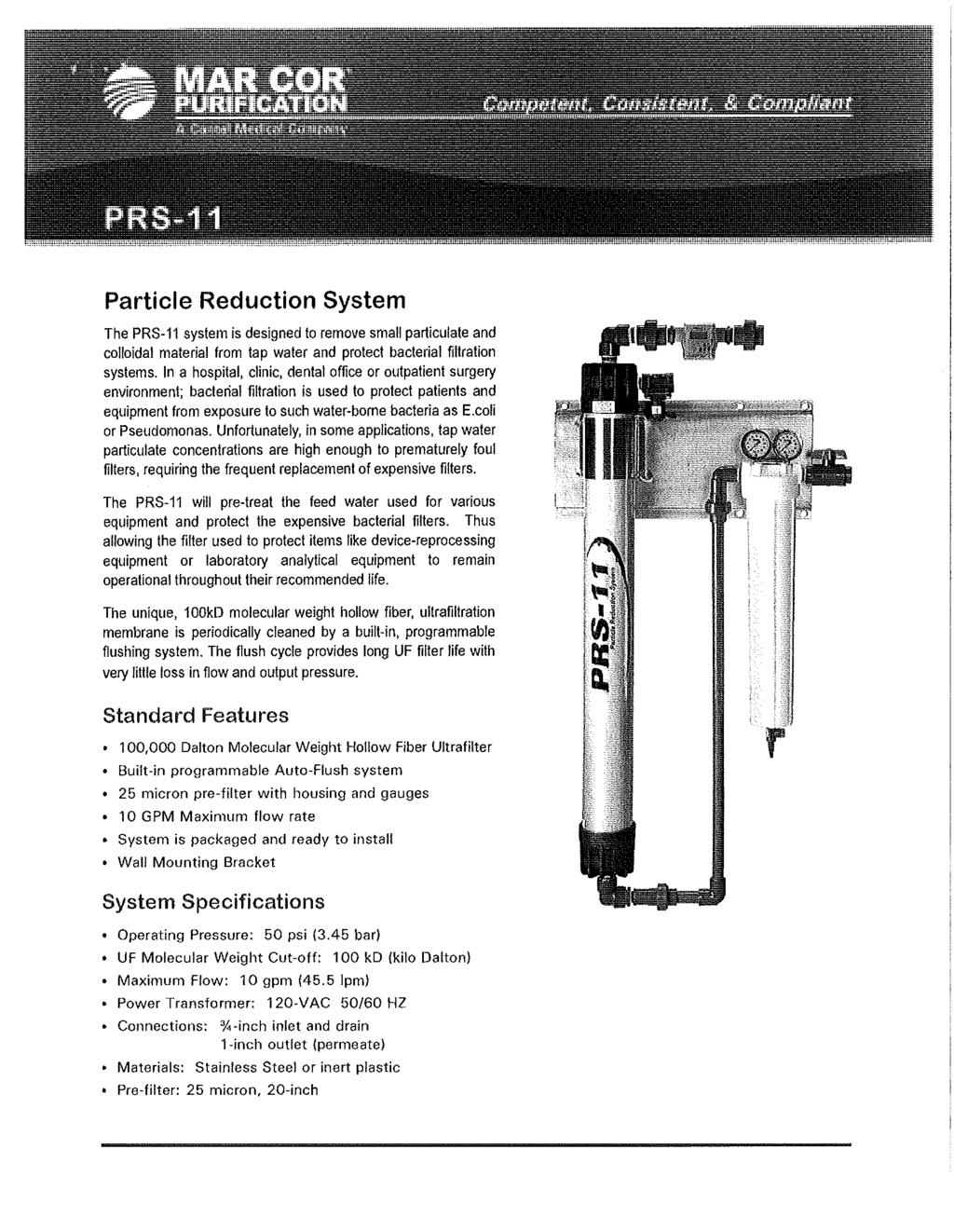
5 CHAPTER ONE: GENERAL INFORMATION PRS General This manual provides the installation and operation procedures for the PRS-11. It is recommended that all information contained in this manual be read prior to installing the system. The PRS-11 system is designed to remove small particulate and colloidal material from tap water and protect bacterial filtration systems. In a hospital, clinic, dental office, or outpatient surgery environment; bacterial filtration is used to protect patients and equipment from exposure to such water-borne bacteria as E.coli or Pseudomonas. Unfortunately, in some applications, tap water particulate concentrations are high enough to prematurely foul filters, requiring the frequent replacement of expensive filters. The PRS-11 will pre-treat the feed water used for various equipment and protect the expensive bacterial filters. This allows the filters used to protect items like device-reprocessing equipment or laboratory analytical equipment to remain operational throughout their recommended life. The unique, 100kD molecular weight hollow fiber, ultrafiltration membrane contained in the PRS-11 is periodically cleaned by a built-in, programmable flushing system. The flush cycle provides long UF filter life with very little loss in flow and output pressure. 1.2 Warranty Information Please read the full text of the Warranty on the last page of this manual. If the system arrives damaged, contact the carrier immediately and file a damage claim. Save all packing materials when filing a claim. Freight damage claims are the responsibility of the purchaser and are not covered under Warranty. 1.3 Service/Technical Assistance If you experience any problems with the installation of the system, contact Mar Cor Purification for assistance. 1.4 Disclaimer The PRS-11 is not designed to produce pyrogen or endotoxin free water. It is a pretreatment system. If bacterial filters have been provided with a medical or pharmaceutical system, they must remain in place Rev A 1 3Sep08
6 PRS-11 This page is intentionally left blank Rev A 2 3Sep08
7 PRS-11 CHAPTER TWO: IMPORTANT SAFETY INFORMATION Throughout this manual, the following safety words and symbols signify important safety issues with regard to installing and maintaining the system. CAUTION GENERAL CAUTION. Indicates information important for the proper operation of the system. Failure to observe may result in damage to the system component(s). In addition to the warnings and cautions in this manual, use the following guidelines for safe installation of the system. Read all instructions before installing system. For your safety, the system is furnished with a low voltage power transformer to plug into the household electrical outlet. Do not replace this transformer with another power supply as this may cause damage to the electronics. Install or locate the system only for its intended use as described in this manual. Do not use corrosive chemicals in this system. Do not install this system if it has a damaged cord or plug, if it is not working properly or if it has been damaged or dropped. Do not immerse the cord or plug in water. Keep the cord away from heated surfaces. Turn the system off and disconnect from the power source before performing any service or maintenance on the system. This system is not intended to filter or to be in contact with any solvents. The system should be grounded according to local electrical codes to prevent the possibility of electrical shock. All electrical connections must be in accordance with local electrical codes and any other applicable laws and regulations Rev A 3 3Sep08
8 WARNING-ELECTRICAL SHOCK HAZARD Failure to follow instructions could result in serious injury. PRS-11 o Do not modify the power supply cord. If it does not fit the outlet, have a suitable outlet installed by a qualified electrician. o Do not use an extension cord with this system. o Check with a qualified electrician if in doubt as to whether the system is properly grounded. If the plumbing is used as an electrical ground, installation of this system may interrupt this ground and a jumper wire around the unit may be required. If the power supply cord is damaged, it must be replaced by the manufacturer or its service agent, or a similarly qualified person. This system is to be installed in compliance with the local plumbing code and any other applicable laws regulations. Water pressure must not exceed 75 psi (5.17 bar). To reduce the water pressure, install a water pressure regulator and set to 50 psi (3.45 bar). Protect from insecticides. Protect from water hammer and freezing Rev A 4 3Sep08
9 CHAPTER THREE: SPECIFICATIONS POWER TRANSFORMER SPECIFICATIONS PRS-11 Input Description Output 120 VAC 50/60 Hertz Power Transformer 12 VDC 1 Amp Figure 1. Components Unit Height (in.) Width (in.) Depth (in.) Operating Weight w/ water (lbs.) PRS Shipping Weight: ~ 45 lbs. All dimensions and weights are approximate Rev A 5 3Sep08
10 SPECIFICATIONS PRS-11 Recommended Operating Pressure.50 psi (3.45 bar) Maximum Operating Pressure.. 75 psi (5.17 bar) Minimum Operating Pressure 30 psi (2.07 bar) Maximum Operating Temperature 104 F (40 C) Minimum Operating Temperature.40 F (4 C) Maximum Operating Differential Pressure...45 psi (3.1 bar) ph Range.3-10 Molecular Weight Cut-Off (MWCO)..100 kd (kilo Dalton) Flow.Max. 10 gpm (45.5 lpm) Feedwater Requirements Feed water type Potable Tap Water ph (Min.) 3 (Max.) 10.0 Pressure (Min.) 30 PSI (2.07 bar) (Max.) 75 PSI (5.17 bar) Temperature (Min.) 40ºF (4ºC) (Max.) 95ºF (40ºC) Rev A 6 3Sep08
11 CHAPTER FOUR: PARTS LIST PRS-11 Replacement Parts for the PRS-11 Ultra Filtration Water Treatment System (Refer to Figure 1 for the letter designation associated with the main components). P1 Ultra Filter Cartridge Assembly P/N: P2 Meter /Controller with Unions P/N: P3 Valve, Solenoid w/ Elec. Lead P/N: P4 1 PVC Elbow w/ Flow Control P/N: P5 Power Supply 120VAC to 12VDC P/N: P6 Bracket, UF P/N: P7 Gauge, PSI, P/N: P8 Filter, 20-inch, 25 micron, 222 P/N: P9 Valve, Ball, 3/4-inch P/N: P10 Valve, Ball, 1/4-inch P/N: P11 Bracket, Mounting P/N: Rev A 7 3Sep08
12 PRS-11 This page left blank intentionally Rev A 8 3Sep08
13 CHAPTER FIVE: INSTALLATION PRS-11 INSTALLING THE PRS-11 General When placing the system into service, use the following guidelines: Make sure the power adapter is not plugged in. Do not immerse the power cord or plug in water. Keep cord away from heated surfaces. 1. Remove the unit from packaging. 2. Inspect the system to ensure the unit has not been damaged during shipping. If the unit has been damaged, save packing material and contact Mar Cor Purification for instructions on returning the unit. 3. Be sure to read and understand the entire Operation Manual before installing the system. Electrical Ensure that the line voltage corresponds to the stated voltage on the power adaptor. Make sure the power adapter and electrical outlet mate properly. For proper operation, make sure the system is not connected to the switched electrical outlet, which could accidentally be shut off. Plumbing Use the following information and guidelines for all plumbing connections: Water Inlet Permeate (Product Water) Drain ¾ NPT 1 NPT ¾ NPT Always use good quality, approved pipe sealant or very thin Teflon tape on all male pipe threads. Do not use Pipe Dope! Do not over tighten connections. Hand tight is sufficient. We recommend using plastic fittings for connecting to the system. This will reduce the possibility of cracking the connections due to over-tightening. The use of unions is highly recommended for ease of installation and future servicing CAUTION Water pressure must not exceed 75 psi (5.17 bar). To reduce the water pressure, install a water pressure regulator and set to 50 psi (3.45 bar) Rev A 9 3Sep08
14 PRS Mount the unit on the wall using the mounting bracket. Locating and Mounting the System Use the following guidelines for mounting the system: Note the location of the water supply, drain, and electrical outlet when choosing a mounting location. For easy reading of the meter/controller, it should be located approximately 64 (163 cm) from the floor. A 4 x 4 area is typically required. Do not mount the system above any electrical equipment or above items that may become damaged if they get wet. Install the system in a location that will allow for future service access. Mount the system to the wall using appropriate mounting hardware capable of supporting 70 pounds. The system is designed to be mounted vertically. 5. Connect potable water to the INLET of the unit. Inlet Water Plumbing - Use the following guidelines for connecting the incoming water supply. Recommend the inlet water plumbing be ¾ NPT or larger. A union should be installed for any future servicing requirements. Connect the system ONLY to a cold water line. Installation of a by-pass should be considered at this time to facilitate future service of the system without interrupting the main supply. Be sure to flush the incoming water line so that clean water, free of debris is available prior to connecting the inlet line. 6. Install the DRAIN line off of the solenoid valve. Be sure to include an approved air gap. Drain Line Plumbing - Use the following guidelines for connecting the drain line. The drain line is used to flush away particle build up when cleaning the system. The drain line should be ¾ inside diameter pipe or tubing. The drain line should be as short as possible, sloping downward without kinks or loops. Be sure the drain line is not blocked or restricted and capable of draining a 10 gpm (45.5 lpm) flow. An air gap must be installed to prevent possible back contamination. A minimum 2 air gap is required. Be sure to secure the drain line at least 2 (5.1 cm) above the drain so that the water flow is directed into the drain without splashing. 7. Install the PERMEATE line to the appropriate device or connection Rev A 10 3Sep08
15 PRS-11 Permeate Line Plumbing - Use the following guidelines for connecting the permeate line (Meter/Controller): a. To ensure the highest quality and safest water, it is recommended a check valve (to prevent back flow) be installed in the water line downstream of the permeate flush tank (if required). The check valve (not supplied) should be mounted close to the system outlet and sized properly for the plumbing line. b. Use only plastic piping materials for this connection. c. Use Teflon tape or a thread sealant for all threaded connections. Do NOT use Pipe Dope! 8. Plug the power adapter into an electrical outlet. 9. Plug the power adapter and the solenoid valve leads into their respective connectors through the openings in the meter/controller cover. Refer to Figure 2. The green LED and LCD screen should light, indicating power is applied to the meter/controller. Figure 2. Meter Connections 10. Program the Meter. Solenoid Valve Connection Power Supply Connection Programming the Meter/Controller 1. Refer to Figure 3 for the location of the meter/controller controls and indicators. Note The meter/controller is factory preset for 160 gallons with a 30 second flush. After the initial flushing, following the programming directions. 2. Open the water tap or the closet downstream faucet to the filtered water (permeate water) Rev A 11 3Sep08
16 PRS Slowly open the inlet water valve (3/4 ball valve) and allow the water to enter the system. Check and if necessary, tighten any fittings or repair as necessary to stop any water leakage. Be sure to turn off the water before making any repairs. 4. Press and hold (approx. 2-3 seconds) the (down arrow) button to initiate a flush. After a 2 minute delay, the solenoid flush valve will open sending air and storage solution to the drain for 30 seconds. Check to make sure the flush water is directed into the drain without splashing and that the drain is capable of handling this volume of water without backing up or flooding. 5. After 30 seconds of flushing, allow water to flow out of the permeate line and through the downstream faucet/tap at a maximum flow for 15 minutes. Turn off the water faucet/tap. After 15 minutes of no water flow, open the faucet/tap for 5 minutes to permit any trapped air to be flushed out; then close the faucet/tap. 6. Refer to the Recommended Initial Operational Setup Table for additional information. NOTE Field tests have shown that flushing more often for shorter periods of time prolongs the life of the membranes better than flushing less often for longer periods of time. 7. Press and hold (approx. 2-3 seconds) the MODE button until the PGM MODE is displayed on the LCD screen; then release. Upon release, Cycle Gal: with a numerical valve will display on the LCD screen. 8. Refer to the Recommended Meter Settings chart on page 15 for the suggested meter/controller settings. 9. Press the (up arrow) button or the (down arrow) button to change to the correct gallon setting. Then press and release the MODE button. 10. FLUSH SECS will display on the screen. Press the (up arrow) or (down arrow) button until the appropriate time setting is reached. 11. Press and release the MODE button. 12. The meter is now programmed for your water supply Rev A 12 3Sep08
17 PRS-11 Figure 3. Meter Controls and Indications Understanding the features of the meter/controller. When power is applied to the meter, the green LCD screen and ON light should be luminated displaying the remaining gallons to flush. When water is flowing through the system, the ON light will blink and the gallon count on the LCD screen will count down. This number indicates the gallons remaining until the unit will flush. If water is flowing when the unit reaches 0 gallons, the green ON and yellow Flush light will blink alternately. The meter will not flush until the water flow has stopped. The unit will then flush for the programmed amount of time. If the PRS-11 does not use the programmed amount of water in a 24-hour period (as when on facility shutdown), the controller will automatically flush for 10 seconds, 24 hours from the last flush. This assures you that you will always receive the freshest, highest quality water. At any time, a manual flush can be done by pressing the (down arrow) button and holding for approx. 2-3 seconds. After a 2 minute delay, the meter will flush for the programmed amount of time and the remaining gallons to flush display will also reset to the programmed setting. Should a power outage occur, the electronics will retain memory of the programmed settings and gallon count. However, if water is used during the outage, it will not be recorded by the controller. When a flush is intiated and after water flow has stopped, both the green and yellow LED s on the controller will be lit solid, indicating that no water is flowing and that the controller is in queue for a flush. There will be a 2-minute delay before the actual flushing begins. This improves flushing on installations, which use a pressure tank on the permeate line. At the end of the 2-minute delay, the unit will complete the flush sequence Rev A 13 3Sep08
18 PRS-11 Disinfecting the System and Lines The system, including all plumbing, must be disinfected after installation and at least once per year to eliminate possible contamination that may have occurred during the installation process and to minimize bacterial contaminations. Chlorine bleach can be used to disinfect the complete system. The amount of bleach used depends on the quantity of plumbing installed downstream of the filter system. Generally, one two ounces of bleach is sufficient to disinfect the complete system. Use the following disinfecting procedure. 1. Open the faucet/tap or drain valve closest downstream to the filtration system and close the water inlet valve; allow the system to depressurize. (First time disinfecting: remove pre-filter and reinstall after the procedure is completed.) NOTE Be sure to remove any additional filtration device that cannot tolerate this procedure prior to flushing the system with chlorine bleach. 2. When the water flow stops, open the pre-filter (see Maintenance section) and pour the liquid bleach (1-2 ounces) into the housing. Be careful not to spill bleach onto clothing or skin. Reattach the pre-filter bowl. 3. Open the furthest faucet/tap from the system and slowly open the water inlet valve of the PRS-11. Allow water to flow out the faucet/tap and close when the smell of bleach is present. Open all other cold water faucet/tap and close when the smell of bleach is present. 4. Allow the system to stand without water flow for at least 20 minutes permitting the bleach to disinfect the piping. 5. After 20 minutes without water flow, open all faucet/tap and flush until the presence of bleach is gone. Close all faucet/tap to complete the disinfection process. Install a new pre-filter. 6. Reinstall or reconnect necessary fittings for filtration devices that were bypassed or removed during this procedure Rev A 14 3Sep08
19 CHAPTER SIX: RECOMMEND METER SETTINGS PRS-11 * Recommended Initial Operation Set-Up of the PRS-11 System WATER SOURCE WATER CONDITION OPERATIONAL EQUIPMENT START-UP METER CONTROL SETTINGS WATER USAGE TO FLUSH POINT FLUSH CYCLE TIME MUNICIPAL WATER PARTICULATE PRE-FILTER (Monthly Exchange) 160 GALLONS 30 SECONDS PROGRAMMED FLUSH SETTING N/A N/A 160 GALLONS 30 SECONDS PREPROGRAMMED NO FLOW SETTING N/A N/A 24 HOUR 10 SECONDS * Based on field-testing experience. Settings may vary with specific water conditions. If flow rate seems to drop over time with initial settings, decrease gallons to flush and increase flush time Rev A 15 3Sep08
20 PRS-11 This page left blank intentionally Rev A 16 3Sep08
21 Changing the Pre-Filter CHAPTER SEVEN: MAINTENANCE PRS-11 The pre-filter should be changed on a monthly basis, unless usage and or poor water quality indicate otherwise. 1. Shut-off any equipment or devices (faucet/tap) being fed by the PRS Shut-off the incoming water supply. 3. Depressurize the system by opening the filter housing drain valve. 4. Remove the filter cartridge by firmly grasping the bowl and turning it clockwise. 5. Remove the 20-inch filter and discard. Install a new pre-filter. NOTE Be sure the O-ring is seated properly. Use silicone based lubricant to help seal properly. 6. Reattach the filter housing by turning the bowl counter clock-wise until tight. 7. Close the filter drain valve and Open the incoming feed water valve slowly to allow water to flow back into the system. Observe pressure gauge. 8. Open any equipment or devices (faucet/tap) being fed by the PRS Rev A 17 3Sep08
22 PRS-11 This page left blank intentionally Rev A 18 3Sep08
23 CHAPTER EIGHT: TROUBLESHOOTING PRS-11 TROUBLE PROBABLE CAUSE REMEDY System does not have power. Meter/Controller LCD display is blank. Power cord is not correctly plugged in. Power cord is not correctly plugged in. Meter/Controller board inoperable. Power transformer inoperable. Plug power cord in correctly and check house circuit breaker fuse or GFI. Plug power cord in correctly and check house circuit breaker fuse or GFI. Replace Meter/Controller. Replace power transformer. No water discharges from system. Low pressure/water flow from system. Flush runs continuously. Flush runs too long. Water splashed at drain during flushing. Inlet valve closed. Inlet pre-filter is plugged. End of capillaries obstructed. No water discharging from system. System in flush mode. Flush cycle not set correctly for water conditions. Solenoid valve stuck open. Inlet water pressure too low. Solenoid valve stuck open. Meter/Controller sending improper signal to solenoid valve. Flush duration set too long. Drain line not positioned properly or drain too small. Open inlet valve. Replace pre-filter. Replace pre-filter and flush system. See instructions under No water discharges from system. under TROUBLE column of this chart. Wait for flush cycle to end. Decrease gallon usage setting so system flushes more often, or add a flush tank to permeate water to aid in flushing process. Repair/replace solenoid valve. Replace pre-filter. Increase inlet water pressure to maximum 75 psi (5.17 bar). Replace solenoid valve. Recheck Meter/Controller settings and reset or repair/replace if required. Reprogram flush cycle for a shorter period of time and decrease gallon setting. Reposition end of drain line or change to a larger drain size. Water leaks from system fitting(s). Fitting broken or loose. Retighten/replace fitting Rev A 19 3Sep08
24 PRS-11 This page left blank intentionally Rev A 20 3Sep08
25 PRS-11 WARRANTY The PRS-11 has been constructed of the finest materials available and manufactured to the highest quality standards. This unit is warranted to be free from mechanical and electrical defects for a period of one year from date of purchase or 12 months after shipment from the factory, whichever occurs first, under normal use and service, and when installed in accordance with Mar Cor Purification s recommendations. To ensure continued, proper operation of the system; follow the maintenance procedure outlined in this Operation Manual. 1. This warranty does not cover cost of installation defects caused by improper storage or handling prior to placement of the system into service. The warranty does not include overtime charges or work done by unauthorized service agencies or personnel. This warranty does not cover normal maintenance or regular adjustments as specified in the operating and maintenance instructions in this manual and/or labor involved in moving adjacent objects to gain access to the system components. This warranty does not cover consumable items such as pre-filters or filtration membranes. This warranty does not pay travel, mileage, or any other charges for Mar Cor Purification Service Technician to reach the system location. 2. Mar Cor Purification reserves the right to make changes in design or add improvements to any product. Changes to update equipment do not constitute a warranty charge. 3. If shipment is damaged in transit, the purchaser should make a claim directly with the carrier. Careful inspection should be made of the shipment as soon as it arrives and visible damage should be noted upon the carrier s receipt. Damage should be reported to the carrier. This damage is not covered under this warranty. 4. Warranty charges do not include freight or foreign, excise, municipal or other sales or use taxes. All such freight taxes are the responsibility of the purchaser. 5. THIS WARRANTY IS EXCLUSIVE AND IS IN LIEU OF ALL OTHER WARRANTIES, EXPRESSED OR IMPLIED, INCLUDING ANY IMPLIED WARRANTY OR MERCHANTABILITY OR FITNESS FOR A PARTICULAR PURPOSE, EACH OF WHICH IS HEREBY EXPRESSLY DISCLAIMED. THE REMEDIES DESCRIBED ABOVE ARE EXCLUSIVE AND IN NO EVENT SHALL MAR COR PURIFICATION BE LIABLE FOR SPECIAL CONSEQUENTIAL OR INCIDENTAL DAMAGES FOR THE BREACH OR DELAY IN PERFORMANCE OF THIS WARRANTY Rev A 21 3Sep08
26
27
28 4450 Township Line Road, SKIPPACK, PA Ph: Fax: Call (800) for additional information or visit
Installation, Operation and Maintenance Manual
 Installation, Operation and Maintenance Manual Model H2F H2Flow Anti-Scale System Chemical-Free, Salt-Free Scale Prevention Introduction The H2Flow Anti-Scale System will condition the tap water providing
1020 Industrial Drive, Orlinda, TN fax
 Operation Manual Ultrafiltration for High Purity Distribution K-A-HPTUF Series 615-654-4441 sales@specialtyh2o.com 615-654-4449 fax TABLE OF CONTENTS Section 1 GENERAL 1.1 Warnings and Cautions... 1 1.2
Installation, Operation, and Maintenance Manual
 Installation, Operation, and Maintenance Manual Product Preservers Anti-Scale System Chemical-Free, Salt-Free Scale Prevention Introduction The Product Preservers Anti-Scale System will condition the tap
NB/NBR NITROGEN BOOSTER FOR AVIATION SERVICE
 NB/NBR NITROGEN BOOSTER FOR AVIATION SERVICE INSTALLATION, OPERATION & MAINTENANCE MANUAL INTERFACE DEVICES, INC. 230 Depot Road, Milford, CT 06460 Ph: (203) 878-4648, Fx: (203) 882-0885, E-mail: info@interfacedevices.com
FlashGARD HP Reverse Osmosis Filtration System Model Number FSTMO75 Part Number
 3M Water Filtration Products FlashGARD HP Reverse Osmosis Filtration System Model Number FSTMO75 Part Number 56123-06 Installer: Please leave this manual with owner/operator. End User: Please retain for
Accu-Tab Systems 2000 P Series by Axiall Corporation
 Accu-Tab Systems 2000 P Series by Axiall Corporation Installation and Operating Instructions Models 2075 P 2150 P For NSF/ANSI-Standard 61 NSF STANDARD 61 applications use NSF/ANSI Standard 60 listed Axiall
DRS4-RM Manual. Set Up Instructions for DRS4 Series Single Tank
 Set Up Instructions for DRS4 Series Single Tank Inspect the packaging of the equipment to confirm that nothing was damaged during shipping. (Figure 1) Remove the resin tank(s) and valve(s) from the packaging.
SSFU SUPER SPRAYFAST UNIVERSAL ADHESIVE APPLICATOR
 S S F U SSFU SUPER SPRAYFAST UNIVERSAL ADHESIVE APPLICATOR MACHINERY DIVISION OWNER S MANUAL UNIT INSTRUCTIONS Please follow all SSFU Safety Instructions. Contact your Duro Dyne Tech Service if you have
NORMAL OPERATING DISPLAYS GENERAL OPERATION
 SunTapWat e rsys t e ms WS1Cl ac kwat e rsof t ne r Owne r smanual MAIN COMPONENTS Your water treatment system is a point of entry (POE) system composed of three components: A. The control valve and computer
WATER HEATER THERMAL EXPANSION TANKS Owner s Manual. Safety Instructions Installation Maintenance Warranty. Models: 2-5 Gallon Capacity
 WATER HEATER THERMAL EXPANSION TANKS Owner s Manual Safety Instructions Installation Maintenance Warranty Models: 2-5 Gallon Capacity Thank You for purchasing this Thermal Expansion Tank. Properly installed
Accu-Tab Systems 1000 Series by Axiall Corporation
 Accu-Tab Systems 1000 Series by Axiall Corporation Installation and Operating Instructions Model 1050 DANGER: DO NOT MIX CHEMICALS! The Accu-Tab chlorinator is designed for use with Axiall approved tablets
GETZ EQUIPMENT INNOVATORS PART NO.: 9G59554 MODEL: MS 36 SC-R HYDROSTATIC TEST PUMP
 GETZ EQUIPMENT INNOVATORS PART NO.: 9G59554 MODEL: MS 36 SC-R HYDROSTATIC TEST PUMP LIMITED WARRANTY Getz Equipment Innovators warrants its products, and component parts of any product manufactured by
Manual. Bypass Feeder. Installation Maintenance Repair Manual. Chemical Addition and Filtering
 Manual Bypass Feeder Chemical Addition and Filtering Installation Maintenance Repair Manual Advantage Controls P.O. Box 1472 Muskogee, OK 74402 Phone: 918-686-6211 Fax: 918-686-6212 www.advantagecontrols.com
Owners Manual Models: 075-AQF-CX. Aquatrol Backwashing Catalytic Carbon Filter. Visit us online at.
 Visit us online at www.uswatersystems.com Aquatrol Backwashing Catalytic Carbon Filter Owners Manual Models: 075-AQF-CX REVISION # 1.0 REVISION DATE October 11, 2017 US Water Systems, Inc. 1209 Country
BS Series Basket Strainer
 BS Series Basket Strainer Operating, Installation, & Maintenance Manual Corrosion Resistant Fluid and Air Handling Systems. Dated 04-26-12 PRESSURE DROP SIMTECH strainers are engineered to offer the lowest
TITAN FLOW CONTROL, INC.
 PREFACE: This manual contains information concerning the installation, operation, and maintenance of Titan Flow Control (Titan FCI) Simplex Basket Strainers. To ensure efficient and safe operation of Titan
ROPV R40 E Series User Manual
 HARBIN ROPV INDUSTRY DEVELOPMENT CENTER ROPV R40 E Series User Manual For Use with the Following ROPV Pressure Vessel Models: R40 300E R40 450E Headquarters Tel:(+86)451-82267301 Fax:(+86)451-82267303
Iron Filter Installation / Operation Manual
 Iron Filter Installation / Operation Manual BrassMaster and BrassMaster Plus Technical Video Library: http://watercontrolinc.com/residential-technical-support/residential-technical-videos BrassMaster technical
KJ4000 Operating Instructions & Parts Manual NSN
 KJ4000 Operating Instructions & Parts Manual NSN 1025-01-473-7710 Mandus Group Ltd. KJ4000 Operators Manual Date: 3 Jan. 2002 TABLE OF CONTENTS General Safety Instructions...Page 1 Operator Instructions...Page
AIR COMPRESSOR. Failure to follow all instructions as listed below may result in electrical shock, fire, and/or serious personal injury.
 2 GALLON AIR COMPRESSOR Model: 7517 DO NOT RETURN TO STORE. Please CALL 800-348-5004 for parts and service. CALIFORNIA PROPOSITION 65 WARNING: You can create dust when you cut, sand, drill or grind materials
Installation and Instructions 2. Product Features 3-6. Key Pad Functions 7. Distributor Information Programming Guide 8. Master Programming Guide 9-14
 Installation and Instructions 2 Product Features 3-6 Key Pad Functions 7 Distributor Information Programming Guide 8 Master Programming Guide 9-14 Dimensional Drawing 15 D-STC & D-SMM Valve Assembly 16-17
Acid- Rite ph Adjustment System 2500 by Axiall, a Westlake Company
 Acid- Rite ph Adjustment System 2500 by Axiall, a Westlake Company Installation and Operating Instructions DANGER: DO NOT MIX CHEMICALS! The Acid-Rite ph Adjustment System is designed for use with Axiall
Vessel Installation and Operating Manual
 For In-ground and Aboveground Pools Vessel Installation and Operating Manual Important Safety Information Please read this manual prior to installation. Nature 2 Express is designed to sanitize in-ground
42045 Heavy Duty ADA Base Model Kit: 85/105 PSI (ADA Compressor Only) Heavy Duty ADA Base Model Kit: 110/145 PSI (ADA Compressor Only)
 Heavy Duty ADA Base Model Kit: 110/145 PSI (ADA Compressor Only)") 42045 Heavy Duty ADA Base Model Kit: 85/105 PSI (ADA Compressor Only) 42047 Heavy Duty ADA Base Model Kit: 110/145 PSI (ADA Compressor Only) 45052 Constant Duty ADA Base Model Kit: 85/105 PSI (ADA Compressor
42045 Heavy Duty ADA Base Model Kit: 85/105 PSI (ADA Compressor Only) 42047 Heavy Duty ADA Base Model Kit: 110/145 PSI (ADA Compressor Only) 45052 Constant Duty ADA Base Model Kit: 85/105 PSI (ADA Compressor
3 GALLON, OILLESS PANCAKE COMPRESSOR INSTRUCTIONS. Item #31289
 3 GALLON, OILLESS PANCAKE COMPRESSOR INSTRUCTIONS Item #31289 The EASTWOOD 3 GALLON, OILLESS PANCAKE COMPRESSOR, with an Integral Air Regulator, efficiently supplies all compressed air requirements for
97C COMPRESSOR KIT 12V PART NO C COMPRESSOR KIT 24V PART NO C COMPRESSOR KIT PART NO
 97C COMPRESSOR KIT 12V PART NO. 00097 97C COMPRESSOR KIT 24V PART NO. 02497 98C COMPRESSOR KIT PART NO. 00098 97C 98C IMPORTANT: It is essential that you and any other operator of this product read and
TactAir PCP Fill Kit/Adapter. Operation Manual
 TactAir PCP Fill Kit/Adapter Operation Manual INTRODUCTION Thank you for choosing a TactAir PCP fill accessory! Always exercise caution when operating this item. It will allow you to fill your PCP airguns
Accu-Tab PowerBase 3070AT by Axiall Corporation
 Accu-Tab PowerBase 3070AT by Axiall Corporation Installation and Operating Instructions The PowerBase 3070AT Chlorinator is NSF STD 50 NSF-Listed for pool applications. ONLY Axiall Corp. Accu-Tab Blue
100C Air Compressor Kit
 10010 100C Air Compressor (standard mounting bracket, CE Spec) 10014 100C Air Compressor (no leader hose or check valve, CE Spec) 10016 100C Air Compressor (with Omega Bracket, CE Spec) IMPORTANT: It is
FLUSHMATE III FLUSHMATE FLUSHOMETER - TANK SYSTEM. Owner s Service Manual. 503 Series. 503 Series
 Owner s Service Manual 503 Series FLUSHMATE III FLUSHOMETER - TANK SYSTEM 503 Series FLUSHMATE A Division of Sloan Valve Company 30075 Research Drive New Hudson, MI 48165 800-533-3450 248-446-5300 http://www.flushmate.com
MODEL Maverick Heavy Duty Aerosol Compressor Operator s Manual
 MODEL 50012 Maverick Heavy Duty Aerosol Compressor Operator s Manual This page left blank intentionally CONTENTS Page No. INSPECTION... 1 GENERAL INFORMATION... 1 SAFETY PRECAUTIONS... 2 BASIC OPERATING
200 PSI COMPRESSORS - MODEL NUMBERS
 200 PSI COMPRESSORS - MODEL NUMBERS 380C AIR COMPRESSOR KIT PART NO. 38033 480C AIR COMPRESSOR KIT PART NO. 48043 380C 480C IMPORTANT: It is essential that you and any other operator of this product read
AIR COMPRESSOR OPERATING INSTRUCTION AND PARTS LIST
 AIR COMPRESSOR OPERATING INSTRUCTION AND PARTS LIST OIL-LESS TYPE IMPORTANT: PLEASE READ CAREFULLY BEFORE STARTING OPERATIONS. THE CONTENTS ARE FOR GENERAL INFORMATION OF ALL THE SIMILAR MODELS. Record
J Air and Water Kit Instructions Part# 02584
 J Air and Water Kit Instructions Part# 02584 Unpacking Please open and inspect your package upon receipt. Your package was packed with great care and all the necessary packing materials to arrive to you
LINEGUARD UF-100 compact water systems point-of-entry
 LINEGUARD UF-100 compact water systems point-of-entry manual Manual LineGuard 08-2012 water solutions lineguard LINEGUARD UF-100 compact water systems installation & operating manual Contents 1 Introduction
Model B-1 Pipe Line Strainer 3, 4, 6 & 8 Inch (DN80, DN100, DN150 & DN200) 175 psi (12,1 bar) General Description. Technical Data
 175 psi (12,1 bar) General Description. Technical Data") Technical Services: Tel: (800) 381-312 / Fax: (800) 71-5500 Customer Service/Sales: Tel: (215) 362-0700 / (800) 523-6512 Fax: (215) 362-5385 Model B-1 Pipe Line Strainer 3,, 6 & 8 Inch (DN80, DN100, DN150
Technical Services: Tel: (800) 381-312 / Fax: (800) 71-5500 Customer Service/Sales: Tel: (215) 362-0700 / (800) 523-6512 Fax: (215) 362-5385 Model B-1 Pipe Line Strainer 3,, 6 & 8 Inch (DN80, DN100, DN150
Interface Devices, Inc. Hydraulic Mini Mule
 Interface Devices, Inc. Hydraulic Mini Mule INSTALLATION, OPERATION & MAINTENANCE MANUAL IMPORTANT! FILE THIS MANUAL IN A SAFE PLACE FOR FUTURE SERVICE & PARTS NEEDS ALWAYS REFERENCE THE SERIAL NUMBER
Electronic Control Pump Instruction Manual
 Limited Warranty G2 Products manufactured by Walrus Pumps Co (Walrus) are warranted to the first user only to be free of defects in material and workmanship for a period of 2 months from date of installation,
Accu-Tab PowerBase 3012AT by Axiall Corporation
 Accu-Tab PowerBase 3012AT by Axiall Corporation Installation and Operating Instructions DANGER: DO NOT MIX CHEMICALS! The PowerBase 3012AT chlorinator system is designed for use with Axiall Corp. approved
3M Water Filtration Products
 3M Water Filtration Products Installation and Operation Instructions for ScaleGard TM HP Reverse Osmosis System Installer: Please leave this manual with owner/operator. Owner/Operator: Please retain for
Instruction Manual - Diaframless TM Ejector Chlorine, Sulfur Dioxide and Ammonia
 Instruction Manual - Diaframless TM Ejector Chlorine, Sulfur Dioxide and Ammonia - 1-122.6010.6 These instructions describe the installation, operation and maintenance of the subject equipment. Failure
HAYWARD FLOW CONTROL FLV SERIES, PVC/CPVC FILTER VESSEL INSTALLATION, OPERATION AND MAINTENANCE INSTRUCTIONS
 HAYWARD FLOW CONTROL FLV SERIES, PVC/CPVC FILTER VESSEL INSTALLATION, OPERATION AND MAINTENANCE INSTRUCTIONS Pg. 1of 15 PLEASE READ THE FOLLOWING INFORMATION PRIOR TO INSTALLING AND USING ANY HAYWARD PRODUCT.
Operation Manual. Carbon Filtration Industrial Drive, Orlinda, TN fax
 Operation Manual Carbon Filtration 615-654-4441 sales@specialtyh2o.com 615-654-4449 fax TABLE OF CONTENTS Section 1 GENERAL 1.1 Warnings and Cautions... 1 1.2 Theory of Operation... 2 1.3 System Illustration...
Cocoa Patio Pond with Lit Spillway
 Cocoa Patio Pond with Lit Spillway REMINDER CALL 1-888-755-5641 BEFORE RETURNING TO STORE. PACKAGE CONTENTS ITEM # GQSPPB/GQSPPW Questions, problems, missing parts? Before returning to your retailer, call
HAYWARD FLOW CONTROL TFS SERIES FLOW METER INSTALLATION, OPERATION AND MAINTENANCE INSTRUCTIONS
 HAYWARD FLOW CONTROL TFS SERIES FLOW METER INSTALLATION, OPERATION AND MAINTENANCE INSTRUCTIONS PLEASE READ THE FOLLOWING INFORMATION PRIOR TO INSTALLING AND USING HAYWARD TFS SERIES FLOW METERS. FAILURE
FloWash. Industrial Filter Cart
 OPERATION AND MAINTENANCE MANUAL FloWash Industrial Filter Cart Read all instructions before installation or operation of equipment. Failure to comply with these instructions could result in bodily injury
RAM 4021-PR. Operation Manual. Worldwide Manufacturer of Gas Detection Solutions
 RAM 4021-PR Operation Manual Worldwide Manufacturer of Gas Detection Solutions TABLE OF CONTENTS RAM 4021-PR For Your Safety... 2 Description.... 2 Setup Mode.... 2 Lights/Alarms.... 3 Operation.... 4
D Series Air and Water Kit Part# 02550
 D Series Air and Water Kit Part# 02550 Unpacking Please open and inspect your package upon receipt. Your package was packed with great care and all the necessary packing materials to arrive to you undamaged.
4 and 8 Station PDS Control Installation & Operators Manual
 4 and 8 Station PDS Control Installation & Operators Manual 1402-15 11/2000 June 2003 MW1402C Chore-Time Warranty 4 and 8 Station PDS Control Chore-Time Warranty Chore-Time Equipment ( Chore-Time ) warrants
INSTALLATION AND OPERATION INSTRUCTIONS
 "GEO-PULSE" THE HEART BEAT OF YOUR GEOTHERMAL SYSTEM This manual is to assist you in your installation and operation of your new "GEO-PULSE" geothermal pumping module. Read the manual thoroughly before
2 GAL AIR COMPRESSOR OPERATOR S MANUAL 1/3HP/2-GALLON IMPORTANT: READ THIS OPERATOR S MANUAL BEFORE USING
 ITEM# AT01101 SKU# 207-1525 OPERATOR S MANUAL 1/3HP/2-GALLON 2 GAL AIR COMPRESSOR IMPORTANT: READ THIS OPERATOR S MANUAL BEFORE USING Toll Free Helpline: 1-888-899-0146 Versions 01 TABLE OF CONTENTS SAFETY
420C AIR COMPRESSOR KIT PART NO C AIR COMPRESSOR KIT PART NO
 420C AIR COMPRESSOR KIT PART NO. 42042 460C AIR COMPRESSOR KIT PART NO. 46043 420C 460C IMPORTANT: It is essential that you and any other operator of this product read and understand the contents of this
IMPORTANT SAFETY INSTRUCTIONS
 IMPORTANT SAFETY INSTRUCTIONS CAUTION - To reduce risk of electrical shock: - Do not disassemble. Do not attempt repairs or modifications. Refer to qualified service agencies for all service and repairs.
Installation and Operation 370ESP (Electric Single-Point Purger) & 370ESPR (Retrofit Purger)
 & 370ESPR (Retrofit Purger)") IB-77 Installation and Operation 370ESP (Electric Single-Point Purger) & 370ESPR (Retrofit Purger) These installation, operation and technical instructions should be used by experienced personnel as a
IB-77 Installation and Operation 370ESP (Electric Single-Point Purger) & 370ESPR (Retrofit Purger) These installation, operation and technical instructions should be used by experienced personnel as a
ULTRA-LIGHT DUTY ONBOARD AIR SYSTEM
 ULTRA-LIGHT DUTY ONBOARD AIR SYSTEM PART NO. 10000 IMPORTANT: It is essential that you and any other operator of this product read and understand the contents of this manual before installing and using
ATD /8 x 50 Retractable Air Hose Reel Owner s Manual
 ATD-31166 3/8 x 50 Retractable Air Hose Reel Owner s Manual Features Heavy-gauge, all-steel reel assembly 8-position ratchet mechanism locks reel at desired hose length 5-position adjustable roller outlet
FLUSHMATE FLUSHOMETER - TANK SYSTEM. 501-A Series. Owner s Service Manual. 501-A Series
 Owner s Service Manual 501-A Series FLUSHMATE FLUSHOMETER - TANK SYSTEM 501-A Series A Division of Sloan Valve Company 30075 Research Drive New Hudson, MI 48165 800-533-3450 248-446-5300 http://www.flushmate.com
INSTALLATION & MAINTENANCE INSTRUCTIONS
 DESCRIPTION / IDENTIFICATION The QBX series valve uses Proportion-Air closed loop technology for Pressure control. It gives an output pressure proportional to an electrical command signal input. The QB1X
SpectraPure PUMPED RO SYSTEMS (PSP) User s Manual for PSP-1500 Systems
 User s Manual for PSP-1500 Systems") SpectraPure PUMPED RO SYSTEMS (PSP) User s Manual for PSP-1500 Systems 2 3 PSP-1500 SYSTEM DESCRIPTION Reverse Osmosis RO Reverse Osmosis utilizes the unique properties of a semi-permeable membrane to
SpectraPure PUMPED RO SYSTEMS (PSP) User s Manual for PSP-1500 Systems 2 3 PSP-1500 SYSTEM DESCRIPTION Reverse Osmosis RO Reverse Osmosis utilizes the unique properties of a semi-permeable membrane to
ACRYLIC FLOW METERS 0-30, 0-70 & LPM
 ACRYLIC FLOW METERS 0-30, 0-70 & 0-120 LPM ASSEMBLY INSTRUCTIONS & INSTRUCTIONS FOR USE R219P86 (0-120LPM) R219P87 (0-70LPM) R219P88 (0-30 LPM) R138P11 Rev. D TABLE OF CONTENTS: 1.0 PRODUCT OVERVIEW...1
Electronic Control Pump Instruction Manual
 TQ Series Electronic Control Pump Instruction Manual 234867 ISO 9001 Certified Walrus America Inc EC Declaration of Conformity Manufacturer: Walrus Pump Co., Ltd. Address: No. 83-14, Dapiantou, Sanjhih
Concentrate Distribution System (Stand Mounted) A-CDS-70-X & A-CDS-TANK-X-ST Industrial Drive, Orlinda, TN 37141
 A-CDS-70-X & A-CDS-TANK-X-ST Industrial Drive, Orlinda, TN 37141") 0 Operation Manual Concentrate Distribution System (Stand Mounted) A-CDS-70-X & A-CDS-TANK-X-ST 615-654-4441 sales@specialtyh2o.com 615-654-4449 fax TABLE OF CONTENTS Section 1 GENERAL 1.1 Warnings and
0 Operation Manual Concentrate Distribution System (Stand Mounted) A-CDS-70-X & A-CDS-TANK-X-ST 615-654-4441 sales@specialtyh2o.com 615-654-4449 fax TABLE OF CONTENTS Section 1 GENERAL 1.1 Warnings and
OPERATING INSTRUCTIONS Pressure Control System PCS-20 through PCS-100
 107 W. Main Street Worthington, PA 16262 Phone: 724.297.3416 Fax: 724.297.5189 http://www.airtak.com OPERATING INSTRUCTIONS Pressure Control System PCS-20 through PCS-100 12-2007 TABLE OF CONTENTS PAGE
PERSONAL AIR BREATHING UNIT
 PERSONAL AIR BREATHING UNIT Operation & Maintenance Manual MARTECH SERVICES C O M P A N Y 1-800-831-1525 Table of Contents INTRODUCTION: Page 2 COMPONENTS DRAWING: Page 3 START UP: Page 4 OPERATION: Page
Installation and Operating Manual
 Safety Instructions Important Information Please read prior to installation ATTENTION! ELECTRICAL HAZARD FOR INGROUND POOLS AND ABOVEGROUND POOLS Installation and Operating Manual IMPORTANT Pool Owner,
MODEL CALIBRATION GAS DELIVERY SYSTEM
 MODEL 1200-26 CALIBRATION GAS DELIVERY SYSTEM Sierra Monitor Corporation 1991 Tarob Court, Milpitas, CA 95035 (408) 262-6611 MODEL 1200-26 CALIBRATION GAS DELIVERY SYSTEM APPLICABILITY & EFFECTIVITY This
NGP-250/500 Nitrogen Generator Quick Start Guide
 NGP-250/500 Nitrogen Generator Quick Start Guide Version: A July 2013 Potter Electric Signal Company, LLC 5757 Phantom Dr., Suite 125 P. O. Box 42037 Hazelwood, MO 63042 Phone: (314) 595-6900 Document
INSTALLATION. and INSTRUCTION MANUAL. for QUALITY AIR BREATHING SYSTEMS. Model 50-P-Mini Portable Systems Outfitted with ABM-725 Monitor
 INSTALLATION and INSTRUCTION MANUAL for QUALITY AIR BREATHING SYSTEMS Model 50-P-Mini Portable Systems Outfitted with ABM-725 Monitor M A R T E C H S E R V I C E S C O M P A N Y P.O. Box 7079 OFFICE: (507)
BRILLIANT WONDERS LED BUBBLERS INSTALLATION INSTRUCTIONS CMP SERIES. Brilliant Wonders LED BUBBLERS
 R BRILLIANT WONDERS LED BUBBLERS INSTALLATION INSTRUCTIONS CMP 25503 SERIES Brilliant Wonders LED BUBBLERS TABLE OF CONTENTS 1. Product Overview....3 1.1 Specifications. 3 1.2 Packing List...3 2. System
AMP Oil Free Manual AMP 50-8-TC AMP 50-6-D AMP General User and Maintenance Instructions
 AMP Oil Free Manual AMP 50-8-TC AMP 50-6-D AMP 50-24 General User and Maintenance Instructions Silentaire Technology 8614 Veterans Memorial Dr. Houston, TX 77088 800-972-7668 Fax 832-327-0669 www.silentaire.com
SPECIFICATIONS Type: Twin stack, single phase Tank: 4 gallon Air Output: PSI; PSI Max PSI: 125 PSI HP: 1.
 2 GALLON TWIN STACK AIR COMPRESSOR Model: 9526 DO NOT RETURN TO STORE. Please CALL 800-348-5004 for parts and service. CALIFORNIA PROPOSITION 65 WARNING: You can create dust when you cut, sand, drill or
AcornVac Vacuum Plumbing Systems - Trouble Shooting Guide
 AcornVac Vacuum Plumbing Systems - Trouble Shooting Guide 1. Accumulators Problem Accumulator is overflowing If Accumulator continues to overflow Correction 1. Push and hold the manual activation button
BRILLIANT WONDERS LED BUBBLERS INSTALLATION INSTRUCTIONS & PRODUCT MANUAL CMP SERIES
 BRILLIANT WONDERS LED BUBBLERS INSTALLATION INSTRUCTIONS & PRODUCT MANUAL CMP 25503 SERIES TABLE OF CONTENTS A. PRODUCT OVERVIEW A.1 SPECIFICATIONS A. PRODUCT OVERVIEW... 3 A.1 Specifications A.2 Packing
4 x 40 Spiral Wound Ultra Filter System
 Better Water LLC 4 x 40 Spiral Wound Ultra Filter System Operator Manual rev. Apr 2015 Better Water LLC. All rights reserved. The content of this manual is the intellectual property of Better Water LLC.
PURITY INSTALLATION INSTRUCTIONS MODEL P40
 Sunshine Pool Products, LLC Manufacturer of Quality Pool & Spa Products 902 West 2010 South, Syracuse, Utah 84075 Voice: 801-825-4523 Website: www.sunshinepool.com Email: info@sunshinepool.com PURITY INSTALLATION
TECHNICAL DATA MAINTENANCE AIR COMPRESSOR MODEL G-1
 Dry 131h 1. DESCRIPTION The Viking Model G-1 Maintenance Air Compressor is an electric motor-driven, aircooled, single-stage, oil-less compressor. The unit is equipped with a check valve and provides a
DFB FLOW METERS (DESIGNED FOR BLENDERS, DUAL TAPER)
") DFB FLOW METERS (DESIGNED FOR BLENDERS, DUAL TAPER) 0-3, 0-15, 0-30 & 0-70 LPM ASSEMBLY INSTRUCTIONS & INSTRUCTIONS FOR USE R219P87-400 (0-70 LPM) R219P88-400 (0-30 LPM) R219P79-400 (0-15 LPM) R219P99-400
DFB FLOW METERS (DESIGNED FOR BLENDERS, DUAL TAPER) 0-3, 0-15, 0-30 & 0-70 LPM ASSEMBLY INSTRUCTIONS & INSTRUCTIONS FOR USE R219P87-400 (0-70 LPM) R219P88-400 (0-30 LPM) R219P79-400 (0-15 LPM) R219P99-400
INSTALLATION & START-UP INSTRUCTIONS. Clack WS1 & WS1.25 METER WATER SOFTENER SYSTEMS
 INSTALLATION & START-UP INSTRUCTIONS Clack WS1 & WS1.25 METER WATER SOFTENER SYSTEMS 1999-2009 QualityWaterForLess.com - 1 - info@qualitywaterforless.com Preface: Thank you for your purchase of a new Water
2 GALLON TWIN STACK AIR COMPRESSOR W/ HOSE REEL
 2 GALLON TWIN STACK AIR COMPRESSOR W/ HOSE REEL Model: 52024 CALIFORNIA PROPOSITION 65 WARNING: You can create dust when you cut, sand, drill or grind materials such as wood, paint, metal, concrete, cement,
TITAN FLOW CONTROL, INC.
 PREFACE: This manual contains information concerning the installation, operation, and maintenance of Titan Flow Control (Titan FCI) WYE Type Strainers. To ensure efficient and safe operation of Titan FCI
Saline C 6.0 Junction Box
 ISHCSJBOX RevA Saline C 6.0 Junction Box Junction Box for Saline C 6.0 Commercial Salt Chlorine Generator Owner s Manual Contents Description...3 Installation...4 Operation...7 Maintenance...8 Parts Guide...9
RAM Operation Manual. Worldwide Manufacturer of Gas Detection Solutions
 RAM 4021 Operation Manual Worldwide Manufacturer of Gas Detection Solutions TABLE OF CONTENTS RAM 4021 For Your Safety... 2 Description.... 2 Setup Mode.... 2 Lights/Alarms.... 3 Operation.... 4 Calibration....
REVERSE OSMOSIS WATER FILTRATION SYSTEM MODEL EWR 4075 INSTRUCTION MANUAL
 REVERSE OSMOSIS WATER FILTRATION SYSTEM MODEL EWR 4075 INSTRUCTION MANUAL Excalibur Water Systems 142 Commerce Park Drive, Unit M & N Barrie, Ontario L4N 8W8 CANADA www.excaliburwater.com 2013.05.7446
Yoke Block Instruction Manual
 Yoke Block Instruction Manual ! WARNING IMPORTANT: READ MANUAL COMPLETELY BEFORE OPERATING THIS DEVICE This manual contains instructions on periodically required checks to be performed by the user. These
Easy Nest Kits. Installation Suggestions
 Easy Nest Kits Installation Suggestions 2 General Recommendations Hydraulics Vacuum breakers should be installed to prevent siphoning. Flexible connectors should follow FRP tank manufacturers recommendations.
INSTALLATION. and INSTRUCTION MANUAL. for QUALITY AIR BREATHING SYSTEMS. Model 50 Systems Outfitted with ABM-725 Monitor C O M P A N Y
 INSTALLATION and INSTRUCTION MANUAL for QUALITY AIR BREATHING SYSTEMS Model 50 Systems Outfitted with ABM-725 Monitor M A R T E C H S E R V I C E S C O M P A N Y OFFICE: (507) 843-4700 P.O. BOX 7079 Toll
Installation & Instruction Manual For Portable Series R.O. units:
 Installation & Instruction Manual For Portable Series R.O. units: Please read carefully before proceeding with installation *System components and appearance may vary from above image. REPLACEMENT AND
Softeners Clack Model V125DTH Medical / Industrial Series Operation and Service Manual
 Softeners Clack Model V125DTH Medical / Industrial Series Operation and Service Manual www.ameriwater.com 800-535-5585 AmeriWater LLC 3345 Stop 8 Rd. Dayton, OH 45414 Clack Softener Manual, 98-0180 Rev.
1800C and 1800C-HC Series Service Regulators
 1800C and 1800C-HC Series Service Regulators Installation Instructions www.elster-americanmeter.com General Information: The 1800C and 1800C-HC Regulators are available as Full Capacity Internal Relief
Operator: Save these instructions for future use!
 INLET PRESS TAP WHITE-RODGERS 36E93-304 Delay-Opening Combination Gas Valve INSTALLATION INSTRUCTIONS Operator: Save these instructions for future use! FAILURE TO READ AND FOLLOW ALL INSTRUCTIONS CAREFULLY
Operating Instructions Model and Hydrostatic Test Pump
 Operating Instructions Model 29200 and 2920 Hydrostatic Test Pump Dimension Weight Pump Pressure for 29200 Pump Pressure for 2920 Gauge for 29200 Gauge for 2920 Inlet Connection Outlet Connection Hose
Bermad Pressure Reducing. Model: 42T
 Bermad Pressure Reducing Pilot Operated Pressure Control Valve Model: 42T Installation Operation Maintenance Manual (IOM) REV. 27.7.17 Page 1 of 12 Safety First BERMAD believes that the safety of personnel
Electronic Control Pump Instruction Manual
 Limited Warranty Products manufactured by Walrus Pumps Co (Walrus) are warranted to the first user only to be free of defects in material and workmanship for a period of 2 months from date of installation,
250C-IG COMPRESSOR KIT 12V PART NO C-IG COMPRESSOR KIT 24V PART NO
 250C-IG COMPRESSOR KIT 12V PART NO. 25050 250C-IG COMPRESSOR KIT 24V PART NO. 25058 IMPORTANT: It is essential that you and any other operator of this product read and understand the contents of this manual
High Pressure Inlet Kits for CONCOA BlendMites and BlendMasters
 ADI 3210-A ADI 3210-A Certified ISO 9001 Certified ISO 9001 High Pressure Inlet Kits for CONCOA BlendMites and BlendMasters Warning: An appropriately sized pressure relief device downstream of the regulator
Model PSI Compressor with 3-Gallon Air Tank 12VDC
 Model 6350 150 PSI Compressor with 3-Gallon Air Tank 12VDC IMPORTANT: It is essential that you and any other operator of this product read and understandd the contents of this manual before installing
VERTICAL AIR COMPRESSORS
 VERTICAL AIR COMPRESSORS MODEL NO: VE15C150, VE18C150, VE25C150 PART NO: 2226010, 2226020, 2226025 OPERATION & MAINTENANCE INSTRUCTIONS LS0715 INTRODUCTION Thank you for purchasing this CLARKE Vertical
CSA Sample Draw Aspirator Adapter Operator s Manual
 30-0951-CSA Sample Draw Aspirator Adapter Operator s Manual Part Number: 71-0367 Revision: 0 Released: 4/30/15 www.rkiinstruments.com WARNING Read and understand this instruction manual before operating
OPERATING AND MAINTENANCE MANUAL
 Series 4300 Engineered Performance TABLE OF CONTENTS 0 INTRODUCTION 1 1 Scope 1 2 Description 1 3 Specifications 1 0 INSTALLATION 1 1 Mounting 1 2 Piping 1 1 Connecting Process Pressure 2 2 Vent Connections
IonGen. Installation Instructions & Maintenance Owner s Manual. Electronic Clarifier for Ponds and Pondless Waterfall Systems
 IonGen Installation Instructions & Maintenance Owner s Manual Electronic Clarifier for Ponds and Pondless Waterfall Systems Made in U.S.A. Aquascape, Inc. St. Charles, IL 60174 Brampton, ON L6T 5V7 www.aquascapeinc.com