SHIP PROPELLER MODELSDeIft
|
|
|
- Mercy Quinn
- 6 years ago
- Views:
Transcription


1

2 Lab. y. Scheepsbouwkunck CAVI TAT IO N I N CE PT kpf Hogeschool SHIP PROPELLER MODELSDeIft Dr.G. KUIPER Publication No. 699 of the Netherlands Ship Model BasinThe Wageningen-Ede Laboratories of MARIN This publication is a summary of the full report with the same title, published as NSMB publication No. 655.
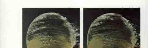
3 Cover and Photography: Th. W. Boekhorst, MARIN Audio Visual Department.


4 MARITIME RESEARCH INSTITUTE NETHERLANDS NSMB, WAGENINGEN/EDE LABORATORIES OF MARIN Aerial view of the NSNB Laboratories in Wageningen Wageningen Laboratories: Haagsteeg 2 P.O. Box 28, 6700 AA Wageningen The NetherlandsTelephone Cables: ModeltankTelex: nsmb nl Aerial view of the Depressurized Towing Tank situated in Ede Ede Laboratory: Niels Bohrstraat AM Ede - The Netherlands Telephone Rotterdam office: Keizerstraat 9 P.O. Box 1555,3000 BN Rotterdam The Netherlands Telephone Telex: nemarnl
5 Marin The Maritime Research Institute Netherlands (MARIN) in Wageningen/Ede and Rotterdam is an independentfoundation working on a non-profit basis. The object of MARIN is to perform scientific research in hydrodynamics, economics, navigation and sociology, affording an integral approach in solving the present-day maritime problems. MARIN has originated from the merger of the Netherlands Ship Model Basin (NSMB) in Wageningen/Ede and the Netherlands Maritime Institute (NMI) in Rotterdam. NSM B was founded in 1929 by the Dutch Government and four large shipping companies. Work started in Wageningen in In the early days, the industrial orders mainly related to optimization of hull forms and propulsion devices by means of model tests in a deep-water basin. In its endeavours to provide a highly scientific level of industrial service, NSMB has continuously explored new fields of specialized service to the shipbuilding, shipping and offshore industries. The character of these specialized services implies that they are often not carried out within industries themselves. As a consequence of this philosophy, development of special-purpose laboratories has gradually taken place, resulting in the building of cavitation tunnels, the seakeeping basin, the shallow water basin, the high-speed towing tank, the wave and current basin, the depressurized towing tank and the ship-manoeuvring simulators. NMI was founded in the early seventies to cover specific areas of maritime research which until then had remained unexplored, notably navigation research and maritime social research. Moreover, the need was felt to integrate several smaller facilities to create an organized entity with a proper balance between the necessary maritime disciplines. NMI was given the task of carrying out economic research, navigation research, operations research and planning, and social research. At present (1983) MARINs staff consists of about 420 persons, of whom 140 have a higher professional education. The annual turnover of scientific industrial orders roughly amounts to 45 million Dutch guilders (19 million U.S. dollars) of which approximately 60% comes from abroad. The activities of MARIN can be broadly subdivided as follows: Economic Research market forecasting optimization of transport systems feasibility studies ports and terminals consultancy Ship powering hull optimization
6 propeller design cavitation Ocean Engineering seakeeping fixed and floating structures mooring systems Navigation Research and Ship Handling design of traffic separation schemes transport risk and analyses marine accident analysis transport safety research manoeuvring tests simulation studies nautical aspects of harbours and fairways training Management and Organization Development consultancy services post graduate courses Computer Services preliminary ship design calculations programmes for shipyard production
7 NSMB testing facilities Name of facility 1. 2a Dimensions in metres Deep-water 252 x 10.5 X 55 basin 0.9 X 0.9 (test sec- tion) Large cavitation tunnel Cavitation tunnel with flow regulator High speed cavitation tunnel 0.4 circular test section 0.04 circular test section 3. Computer centre CDC Cyber 175 computer, 2 paper tape drawing machines 4. Seakeeping 100 x 24.5 x 2 laboratory (pit depth 6) 5. Shallow water 216 x X basin 1.25 (water-depth is variable) Waveandcurrent laboratory High speed towing tank Manoeuvring simulator (hybrid computer) Depressurized towing tank 60 x 40 x 1.20 (water-depth is variable) (pit depth 3) 220 x 4 X x 1 8 x 8 Type of tests Resistance, propulsion, vibratory forces, etc. Cavitation tests with propellers, profiles etc. in various types of flows, fluctuating pressures on hull. Cavitation tests with propellers in simulated axial wake. Fundamental cavitation studies. Hydrostatic, stability, trim, etc. calculations. Design of ships, including economic calculations. 5 Ship motion measurements; necessary power increase to maintain speed; bottom and deck pressures; water shipment and screw racing, wave-induced shear forces, bending and torsional moments; measurements on semi-submersibles etc. All in regular and irregular waves. Resistance and propulsion in shallow water; squat and trim measurements; transverse forces, yawing moment and rudder torque on captive model; resistance and performance in waves; ship motions in regular and irregular waves; motions, mooring and anchor-line forces of semisubmersibles or moored structures; oscillation tests; manoeuvring tests, etc. Determination of feasibility of vessel configurations, with respect to waves, current and wind; motion and force measurements; spiral and turning circle tests; tests on mooring systems, etc. Testing planing hulls; high speed propulsion devices; ice breaking studies in simulated ice fields; testing offshore structures in waves. Training in ship handling, development of navigational aids; design of harbour entrances; development of criteria for manoeuvring, etc. Resistance, propulsion and propeller cavitation tests; flow visualization tests; wave breaking phenomena at the bow; wake surveys; propellerinduced vibratory forces in shaft and on hull; acoustical measurements; etc.
8 CONTENTS 1. INTRODUCTION i 1.1. Cavitation 1.2. Cavitation inception 1.3. Scaling of cavitation 1.4. Cavitation scale effects 1.5. Nuclei 1.6. Viscous effects 1.7. Purpose of this publication EXPERIMENTAL INVESTIGATIONS The experimental approach Types of cavitation The calculated pressure distribution on propellers B, S andv The test facilities Stimulation of inception 13 THE BOUNDARY LAYER ON THE BLADES OF PROPELLER MODELS Paint tests Results of paint tests Laminar separation Rough surface effects Some features of the boundary layer on normal propeller blades 21 BUBBLE CAVITATION. 23 SHEET CAVITATION 27 VORTEX CAVITATION 29 CONCLUSIONS 34 Nomenclature 36 Appendix 37 i 1 i
9 1. Introduction 1.1. CAVITATION Cavitation in a fluid occurs when the pressure is low, usually in regions with a high flow velocity. Due to the low pressure,parts of the fluid can become vapor. The regions in which vapor exists are called cavities. Cavitation inception occurs when the process of vaporisation begins CAVITATION INCEPTION Vapor and fluid are in equilibrium when the pressure in the cavity is at the vapor pressure. In practical cases the pressure in a cavity is indeed close to the vapor pressure. However, to obtain inception a much lower pressure in the fluid is often necessary. In that case there is a threshold for cavitation. This threshold can be very high. Briggs (Journal of Appi. Phys., 1950) found cavitation inception in pure standing water only at a pressure of -277 bars, while the equilibium pressure was at mbar Usually water is not very pure and contains solid particles as well as air. This makes the threshold lower, but also unpredictable SCALING OF CAVITATION Cavitation on ship propellers is investigated on model scale in a cavitation tunnel or in a depressurized towing tank, where the size of the ship propeller is reduced with the scale factor X. To obtain a similar condition as on the prototype two scaling parameters have to be maintained, viz, the advance ratio J and the cavitation index D where n J U nd (1) 1

10 G n 22 2pn D The advance ratio J is a measure for the propeller loading and can be replaced by the thrust coefficient T' where K T T 24 Pn D where T = propeller thrust N U = advance velocity of the propeller n sec n rotation rate of the propeller sec 1 D = propeller diameter m Po = static pressure at the shaft Nm2 p = specific mass of water kg m3 = vapor pressure Nm2 The influence of gravity and of the presence of a free water surface above the propeller will be ignored in this publication. The propeller inflow on model- and full scale are assumed to be similar in every respect CAVITATION SCALE EFFECTS When both the advance ratio (and thus the propeller loading) and the cavitation index are the same on the model and the prototype the cavitation pattern on the model propeller is also similar to that on the prototype, provided that inception also takes place at the vapor pressure. As mentioned, this is not always the case and this leads to differences between the cavitation on the model and on the prototype. These differences are called scale effects on cavitation inception. There are other possible scale effects, e.g. on the propeller inflow. These effects will not be addressed in this report. 2
11 1.5. NUCLEI The bond between the water molecules, which prevents inception of cavitation, can be broken by the presence of small amounts of free gas. Due to the surface tension this gas will be present in the form of small spherical bubbles with a diameter of say 10 to 100 pm. These bubbles are called nuclei. In sea water these nuclei are constantly generated by breaking waves and probably also by micro organisms. In a cavitation tunnel these bubbles are generated by the pump or are recirculating from the cavitating test body. In standing water, as in a depressurized towing tank, these bubbles will either dissolve due to the surface tension or will rise to the surface. Free gas may still be present in standing water, e.g. in cracks of small solid particles. Consider the growth of two nuclei of 20 and 100 pm initial diameter when the pressure decreases linearly to zero. Assuming that no gas dissipation occurs through the bubble wall the result is shown in Figure 1. There is a distinct point at which the bubble growth becomes very rapid. This is the pressure at which the gas bubble becomes unstable and this pressure is called the critical pressure p 4s cv 3R cnt in which R cnt is the radius of the gas bubble at the critical pressure R cnt = (-) 2s s is the surface tension and K is a constant, depending on the amount of gas in the bubble, which depends on the initial conditions, e.g. on the initial bubble size R o 3


12 R Lm Po6O mbar P m b. r CC Pc - - VAPOR PRESSURE Rc r it Ro0 il -50 o R0: 10Lm Rcrit TIME o -20 Fig..2. Bubble growth of air bubbles in water when the pressure decreases. Since the bubble growth is very rapid when the pressure is below the critical pressure we can consider the critical pressure as the inception pressure. From eqs. 4 and 5 two important features of the thus defined inception pressure can be found: - the inception pressure is always lower than the vapor pressure, - the inception pressure depends on the amount of gas in the nucleus, so on its initial size VISCOUS EFFECTS From investigations on headforms (e.g. Arakeri and Acosta, Journal of Fluids Eng., 1973) it is known that also the boundary layer on a body can affect the inception pressure, especially the transition of the 4
13 boundary layer from laminar to turbulent flow or the existence of a separation bubble. A separation bubble occurs when the laminar boundary layer separates from the wall. This separated shear layer is unstable, becomes turbulent and reattaches to the wall. Thus a short "dead-water region" is formed below the boundary layer, the so-called laminar separation bubble. These viscous effects influence cavitation inception probably by local low pressures occurring in the transition region or in the reattachment region. The critical pressure, as described in section 1.5, is no longer the mean pressure on the body or on the propeller blade, but is the minimum pressure occurring in the boundary layer. Apart from the nuclei size distribution the inception pressure consequently also becomes dependent on the boundary layer, which is controlled by the Reynolds number and by the pressure distribution on the blades. (The blades are considered smooth and the influence of turbulence on the boundary layer will be ignored in this publication) The Reynolds number on the propeller blades can be characterized by the propeller Reynolds number Re = 2 nd n \) (6) Since on the prototype of a propeller blade the boundary layer will be turbulent in the minimum pressure point (where inception occurs), the aim will be to attain a turbulent boundary layer at that point on model scale as well PURPOSE OF THIS PUBLICATION At the Netherlands Ship Model Basin the influence of the nuclei content of the fluid and of the boundary layer of the propeller blades on cavitation inception on model propellers was investigated. Also some means to reduce the scale effects of the experiments were developed. The results were published in a thesis (Kuiper, NSMB Public. No. 655, 1981). In the present publication these results are summarized and discussed 5
14 with Special emphasis on practical application in cavitation tests and in cavitation prediction. The Plates at the end of this publication are from the thesis. They are referred to when useful in this report. A short description pertaining i;o the Plates is given in the Appendix. 6
15 2. Experimental investigations 2.1. THE EXPERIMENTAL APPROACH Experiments were carried out with propeller models in uniform axial inflow. This made it possible to investigate inception of cavitation on propeller blades without creating a complex interaction between the propeller inflow and the propeller itself. Scale effects on propeller inflow are thereby excluded TYPES OF CAVITATION The pressure distribution on propeller blades determines the type of cavitation. When a sharp low-pressure peak exists at the leading edge of the propeller blades sheet cavitation will occur. When the pressure drop is gradual and the minimum pressure occurs away from the edges bubble cavitation will occur. In the tip region of the propeller blades a vortex can be generated, depending on the loading of the propeller tips, which leads to tip vortex cavitation. Since the inception conditions can be different for these types of cavitation three propellers were designed, exhibiting these three types of cavitation exclusively in design condition. Propeller S has thin blades with little camber, which leads to sheet cavitation. Propeller B has thick blades and larger camber, leading to bubble cavitation. Both propellers S and B have a strongly reduced pitch at the tip to avoid tip vortex cavitation. Propeller V has nearly the same pitch at all radii, leading to a strong tip vortex. The geometry of these propellers is given in Figure 2. The mentioned types of cavitation are typical on ship propellers. Other types, as cavitation in free shear layers, were not investigated because on ship propellers separated flow regions are generally avoided. 7


16 050 nr PROPELLER B 4 BLAOS O ro,340m A5 (A ( tic0,7 0,0Th nr PROPELLER S 4 BLADS D 0.340m A5 IA c tic aig. 2. Geometry of Propellers. 8
17 L \ xic PROPELLER S AT J J = cp 'i; YR o......_._ xic PROPELLER S AT J 0.6 J = 0.6. Fig. 3a.b. Pressure distribution on the suction side of propeu.er S. 9


18 -20 cp VR x/c PROPELLER B AT J 0.4 C. J = 0.4. I I j \. 0.3 cp r, , x/c PROPELLER B AT J 0.6 J = 0.6. Fig. 3c.d. Pressure distribution on the suction side of propeller B r, /R 10
19 e. J = cp g 08 nr 07 o 03 _iuuuiiiiiiuiftiiiti lo XfC PROPELLER V AT J:05 J'. J 0.6. Fig. 3e.f. Pressure distribution on the suction side of propeller V
20 a The choice of uniform axial inflow also means that the cavitation pattern on the propellers is nearly steady and independent of the blade position. Cloud cavitation, occurring behind unsteady sheet cavitation, is therefore also not investigated. This type of cavitation, however, is typical for developed cavitation and does not pose inception problems THE CALCULATED PRESSURE DISTRIBUTION ON PROPELLERS B, S AND V The pressure distribution on the suction side of the propellers B, S and V, is given in Figures 3a to f. Note that in these figures the basis of the pressure coefficient at each radius is shifted as indicated at the right hand side. The indicated C scale refers to r/r = 0.3 and should be shifted for other radii too. These pressure distributions are given for two different propeller loadings. The pressure distribution is given in dimensionless form as the sectional pressure coefficient C. The vapor pressure generally is made non-dimensional in a similar way as the sectional cavitation index Q. (For definitions see the list of nomenclature). When no cavitation scale effects occur inception of cavitation will take place at a certain propeller section when Q - C(mjn) (7) When cavitation on propeller blades is assessed both the sectional cavitation index O and the minimum pressure coefficient have to be compared as a function of the radius. (Note that the sectional cavitation index is different from the propeller cavitation index G, as given in eq. 2) THE TEST FACILITIES The tests were carried out in two facilities: the NSMB large cavitation tunnel and the NSMB Depressurized Towing Tank. An impression of both facilities is given in Figures 4 and 5. 12
21 The conditions in both facilities are different (nuclei content, Reynolds number) and comparison of the results from both facilities is important to assess the scale effects in each facility STIMULATION OF INCEPTION Since cavitation inception is always delayed as compared with the theoretical criterion of eq. 7, some inception stimulating measures were developed in order to reduce the scale effects. Electrolysis was applied to generate bubbles upstream of the propeller. An electric tension between two poles results in the formation of hydrogen and oxygen out of water. In the towing tank the poles were sets of thin 900mm SQUARE WORKING SECTION Fig. 4. The IVSMB Large Cavitation Tunnel-. 13

22 Fig. 5. The NSMB Depressurized Towing Tank.


23 wires (0.3 mm in diameter), in the cavitation tunnel the poles were thin steel strips, glued to a wooden foil. In both cases these devices were mounted 1.6 n upstream of the propeller. Variation of the voltage between the poles varies the electric current and thus the amount of gas produced. Artificial roughness was applied at the leading edge of the blades (over about 1 mm) to change the boundary layer. The roughness elements were 60 jm carborundum particles, glued to the surface with a very thin layer of laquer. The roughness was applied over a very short distance Only, so that the own resistance of the roighness elements was negligible and the propeller performance was not affected significantly. Fig. 6. Application of roughness at the leading edge. 15
24 3. The boundary layer on the blades of propeller models The boundary layer on a foil starts at the stagnation point as a laminar boundary layer. In the transition region, the location of which depends among others on the Reynolds number, this laminar boundary layer changes into a turbulent one. Because the friction coefficient of a turbulent boundary layer is much higher than that of a laminar one, the position of the transition to turbulence influences the drag of the foil. In terms of propeller forces this means that the propeller torque (and to a lesser degree also the propeller thrust) depends on the location of transition. When the propeller Reynolds nunber is increased (by increasing the rotation rate and the advance velocity simultaneously) the transition region will move upstream towards the leading edge and the torque will increase. Since the propeller Reynolds number of the full scale propeller is very high it can be expected that in that case transition occurs very close to the leading edge. Therefore the propeller Reynolds number of the model propeller has to be high enough to have the transition region near the leading edge too, so that regions of laminar boundary layer flow are avoided. It is often assumed that such a condition without laminar boundary layer flow is obtained when the propeller torque becomes nearly independent of the Reynolds number. Based on measurements of propeller thrust and torque as a function of Reynolds number a minimum sectional Reynolds number of 2 x l0 at 0.7 R is often chosen as a criterion for turbulent boundary layer flow on the model propeller. This corresponds with a propeller Reynolds number of about 1.5 x l0 for the propellers under investigation. Since it is assumed that above this Reynolds number transition occurs close to the leading edge no scale effects on cavitation inception were expected. 16


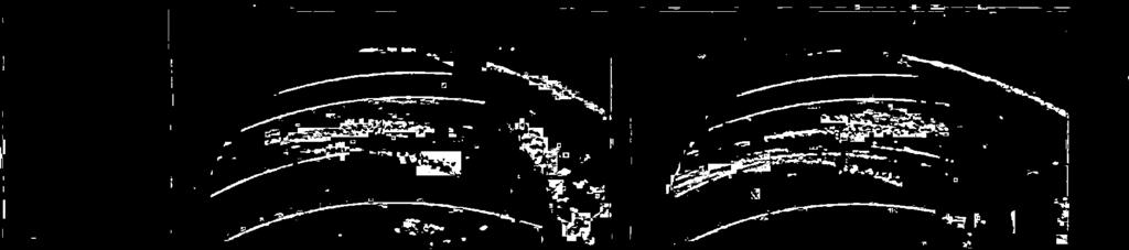
25 DIRECTION OF ROTATION SMOOTH WITH ROUGHNESS PLATE 32. EXAMPLE OF PAINT TEST WITH AND WITHOUT ROUGHNESS AT THE LEADING EDGE. PROPELLER B AT AO4. R:1. PROPELLER B D :024 PROPELLER B D: 034 PROPELLER B D:O48 n: 24 n: 12 n: 6 PLATE 3.4. PAINT PATTERNS ON TNREE PROPELLERS HITH DIFFERENT SIZE (1'o.W: R:=2.12O6).


26 Re 1.1x10⁶ Ree: 17x106 PLATE B.1O. PAINT PATTERN ON PROPELLER B AT J=O.6. Ree: 11x106 Ren: 17x106 PLATE PAINT PATTERN 01V PROPELLER B AT Jr0.4.


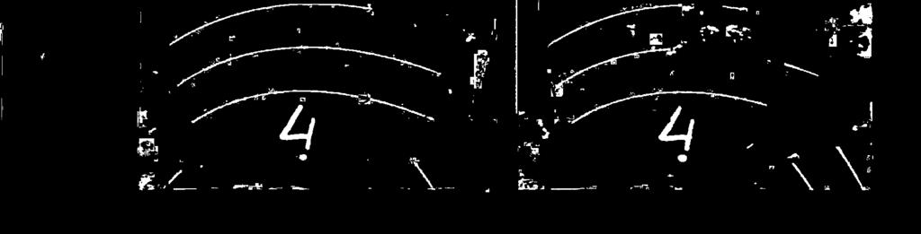
27 Ree: 1.1 x10⁶ Re 1.7 x 10⁶ PLATE PAINT PATTERN ON PROPELLER S AT J=O.6. PLATE 3.i. PAINT PATTERN ON PROPELLER S AT J=O.4. R1.2x2O6. m


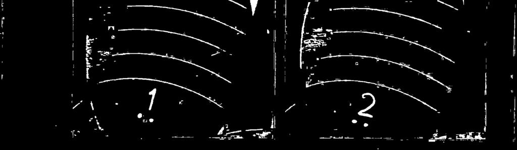
28 PLATE i?. DIFFEREiVCES LETWEEIV THE ELATES WEST LAMThAR SEPAR/i1ON (PROPELLER S AT J-O.5, Re-2.1x10⁶).


29 J 060 J r 0.55 J r 050 J 045 J ro.40 PLATE THE PAINT PATTERN ON PROPELLER S AT VARIOUS WADINGS. (R1. Lr106).


")


30 Ren: 1.1 x10⁶ Rea: 0.56 x10⁶ PLATE PAINT PATTERN ON PROPELLER PLATE PAINT PATTERN ON PROPELLER B* =) ql B AT JrO.28. Rez1.1 x106 Ren: 17x106 PLATE 20. PAINT PATTERN OF PROPELLER V AT JO. 4.

31 I = 1.6 A/rn I 3.2 A/rn I = 8.0 A/rn I :16.0 A/rn I :32.0 A/rn SLATE 5.4. TSE EFFECT OF GAS PRODUCTION ON ELECTROLYSIS. (V=3 rn/sec, p2?o rnbar, WIRE DIAMETER 0.9 n).

32 O A/rn 0.4 A/rn 0.8 A/m 2.0 A/rn PLATE VARIATION OF ELECTROLYSIS CURRENT ON PROPELLER B AT JO. t. (Re rl. 1x10⁶, ø=1. 0).


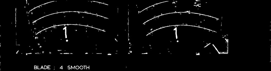
33 WITHOUT ELECTROLYSIS WITH ELECTROLYSIS BLADE : 4 SMOOTH BLADE i ROUGHENED AT THE LEADING EDGE PLATE 6.6. CAVITATION OBSERVATIONS IN TRE CAVITATION TUNNEL. PROPELLER B AT J0.6. (a =0.92, R-2.11x10⁶).


34 WITHOUT ELECTROLYSIS WITH ELECTROLYSIS BLADE 4 SMOOTH BLADE i ROUGHENED AT THE LEADING EDGE PLATE CAVITATION OBSERVATIONS IN THE CAVITATION TUNNEL. PROPELLER B AT JO.4. (o0.92, Re2. 11x106). XIV


.")
35 Ä. ROUGH SMOOTH PLATE CAVITATION OBSERVATIONS IN THE CAVITATION TUNNEL AT HIGH REYNOLDS NUMBER. (R=2.88x1O6, arl.15 JO.4). ROUGH SMOOTH PLATE?. 10. CAVITATION OBSERVATIONS IN THE CAVITATION TUNNEL ON PROPELLER S AT JO.6. (Re2.11xlO6, ao.92).


.")


36 ROUGH SMOOTH PLATE 7.5. CAVITATION OBSERVATIONS IN TSE CAVITATION TUNNEL ON PROPELLER S AT J0.4. (R 1.?8x1O6 2.3). n n ROUGH SMOOTH PLATE 7.6. CAVITATION OBSERVATIONS IN TSE CAVITATION TUNNEL ON PROPELLER S AT J=O.4. (Rer1.S6x1O6, o2.2).


37 Investigations with oil and paint on propeller blades reported in the literature (e.g. Meyne, 1972) indicated already that also in the case of a Reynolds independent thrust- and torque coefficient considerable regions with a laminar boundary layer could still exist on the blades. This would imply that the risk of boundary layer effects on cavitation inception remains. This will be investigated in the following sections PAINT TESTS To investigate the boundary layer on propeller blades the paint test was further developed. In this paint test a layer of paint (lead-oxide with fluorescent pigment) was applied at the leading edge of the propeller, as shown in Figure 7. The propeller was subsequently investigated at the required number of revolutions and forward speed, so that the paint formed very thin streaks on the propeller surface. These streaks were hardly visible by eye, but could be observed and photographed using ultra-violet illumination, Fig. 7. Application of paint. 17
38 which made visible the fluorescent dye in the paint. The difference in friction between a laminar and a turbulent boundary layer causes a difference in thickness of the paint streaks. But, because the centrifugal force on the paint particles is constant at a certain radius, this difference in friction also causes a change in direction of the paint streaks. The streaks in a laminar boundary layer are more outwardly directed than those in a turbulent region. This can be seen in Plate 3.1, where on the smooth blade the boundary layer on the suction side of propeller B is laminar until in the midst of the blade the streaks become thinner and change in direction, indicating transition from laminar to turbulent flow. With these paint tests the effect of leading edge roughness can also be verified, as is shown in Plate 3.1. On the roughened blade the boundary layer is turbulent over nearly the whole blade area. Only near the hub some laminar regions remain RESULTS OF PAINT TESTS The paint tests confirmed that considerable regions of laminar flow remained, both on the suction and on the pressure side of the blades. This is shown for the suction side of propeller B in Plates 3.1, 3.4, 3.10 and 3.11, for propeller S in Plate 3.14 and for propeller V in Plate The lowest propeller Reynolds number used in these tests was 1.1 x 10⁶, which is about four times higher than the criterion for Reynolds independent torque, as mentioned before. These figures also show that an increase of the propeller Reynolds number has only a small effect on the position of transition. The propeller Reynolds number of 1.7 s io6 was the highest value which could be obtained in the Depressurized Towing Tank. Although higher Reynolds numbers are possible in a cavitation tunnel it is clear that this will generally be insufficient to bring the transition region close to the leading edge. 18
39 Transition occurs earlier in an adverse pressure gradient (when the pressure increases) and is delayed by a favourable pressure gradient. The pressure distribution on the propeller blade can therefore influence the location of transition. These effects, however, were also small on the propeller blades. Propeller S at J 0.6 (Figure 3b) has a low pressure peak near the leading edge, very similar as propeller B at J = 0.4 (see Figure 3c). Still the transition region remains near midchord (Plates 3.11 and 3.14). This is also the case (Plate 3.10) when the pressure distribution near the leading edge is different, (Figure 3d) as on propeller B at J = 0.6. The results of paint tests, as discussed until now, illustrate that it is very difficult indeed to move the transition region towards the leading edge. The fact that propeller thrust and torque are nearly Reynolds independent does not mean that no laminar boundary layer regions are present on the model propeller. There are, however, two mechanisms which can create a turbulent boundary layer over the whole blade. These will be discussed next LAMINAR SEPARATION When the pressure peak becomes very sharp the laminar boundary layer will separate from the blade surface and form a "separation bubble". This can be seen from the paint pattern of Plate The occurrence of laminar separation is independent of the Reynolds number in the range of Reynolds numbers used on model propellers, and depends on the pressure distribution only. Laminar separation occurs abruptly when the pressure gradient increases, as is illustreated by the abrupt end of the separation bubble towards the blade tip. The chordwise length of the separation bubble can be very small, in the situation in Plate 3.15 the length is larger than usual. Downstream of the separation bubble the boundary layer is turbulent. 19

40 As will be shown later, laminar separation has a profound effect on cavitation inception. Therefore it is useful to point out the sensitivity of laminar separation to the pressure distribution, and thus to the shape of the leading edge. Plate 3.15 illustrates that the laminar separation bubble extends more outward on blade 4 than on blade 2. Apparently this is caused by differences in blade geometry. This becomes even more pronounced at a somewhat lighter loading, as shown in Plate 3.17, where all blades are shown in the same condition. These differences could be traced to very small differences between the blades using a special blade edge microscope. So when laminar separation is about to occur the sensitivity for inaccuracies in the blade geometry increases dramatically. The sensitivity of laminar separation to the pressure distribution also makes that a change in propeller loading changes the separation region rapidly. This is illustrated in Plate At J = 0.6 the boundary layer is laminar and attached near the leading edge. The separated region grows rapidly with an increase in loading. The consequences of this sensitivity of laminar separation will be discussed later ROUGH SURFACE EFFECTS Sometimes turbulent streaks were observed in regions of laminar flow, as on Plate 3.14 at the higher Reynolds number. This is caused by surface irregularities. Because the boundary layer becomes thinner with increasing Reynolds number the surface irregularities become relatively more important. At a certain Reynolds number these irregularities will trip the boundary layer to turbulence, specifically when they are in regions with an adverse pressure gradient, behind the minimum pressure point. When the Reynolds number is further increased these turbulent streaks will increase in number and make the boundary layer turbulent over the whole blade. This occurs frequently on propeller models. It must be emphasised that, although the boundary layer becomes turbulent from the leading edge, such a case j 20
41 is different from the situation where natural transition takes place near the leading edge on a smooth blade. The latter condition would occur at a much higher Reynolds number, if the blades were completely smooth. When surface imperfections cause transition the blade is actually fully "roughened", although the roughness is due to insufficient finishing of the blades. This effect of inadvertent roughening is aggravated in a cavitation tunnel, where tiny particles, circulating with the tunnel water, attach themselves to the leading edge of the propeller model SOME FEATURES OF THE BOUNDARY LAYER ON NORMAL PROPELLER BLADES The pitch near the tip of the blades of propellers B and S is strongly reduced to avoid tip vortex cavitation. Normally the pitch distribution is closer to a constant value, as is the case with propeller V. Laminar separation of the boundary layer starts near the tip then and the separated region grows towards the hub with increasing loading, as is illustrated in Plate 3.20 (where at the higher Reynolds number also a turbulent streak is present). The laminar boundary layer region is abruptly cut off near the tip due to the occurrence of a laminar separation bubble near the leading edge. In Plate 3.20 the separation bubble is very small and therefore cannot be seen on the picture. From the foregoing the characteristics of the boundary layer on the suction side of a propeller blade can be sketched as in Figure 8. In the region AB a laminar separation bubble occurs. The length AB is independent of the Reynolds number and depends strongly on the pressure distribution and thus on the propeller loading. The region CD is a transition region. Its location depends on the Reynolds number, but this dependence is only weak. The region DE is a region of laminar separation in the midchord region, which may occur near the hub. This phenomenon is independent of 21
42 TURBULENT AB SHORT LAMINAR SEPARATION BC CRITICAL RADIUS CD TRANSITION REGION DE LAMINAR SEPARATION BUBBLE Fig. 8. Boundary layer regions on the suction side of a propeller. the Reynolds number (until a critical Reynolds number, which normally exceeds the numbers used in model testing) The cavitation behaviour of the propeller models can now be investigated and correlated with the propeller boundary layer. 22
43 4. Bubble cavitation The occurrence of bubble cavitation depends on the nuclei content of the water, because every bubble cavïty stems from a gas nucleus in the flow. This nucleus becomes unstable, as illustrated in Figure 1, and grows to a visible cavity. When the number of nuclei is varied this affects bubble cavitation. An example is shown in Plate 6.5, where the number of bubbles is varied by electrolysis. When electrolysis is used small bubbles are generated on the poles: oxygen bubbles on the anode wire, hydrogen bubbles on the cathode wire. These bubbles can act as nuclei. The bubbles, produced by thin wires in a flow due to electrolysis are very small. An example is given in Plate 5.4. There the cathode wire is shown. It has a diameter of 0.9 min. Only at higher currents the many very small bubbles, shed from the wire, coalesce in the vortices behind the wire and then they become somewhat larger in size. Since for cavitation inception near the vapor pressure a minimum bubble size is required, the current used for electrolysis should exceed a certain minimum. This gives problems at higher speeds and pressures, e.g. in a cavitation tunnel, because excessive currents are required then. Electrolysis therefore is a proper means for generating bubbles in the Depresaurized Towing Tank, but is less suited for the cavitation tunnel. There application of roughness may be a substitute, as will be discussed hereafter. In the Depressurized Towing Tank electrolysis is necessary to investigate bubble cavitation because the nuclei content of the standing water is very low. It is generally assumed that in a cavitation tunnel enough nuclei are present for proper scaling of bubble cavitation. This, however, proved to be overoptimistic, as is shown in Plate 6.6. In the condition of Plate 6.6 application of electrolysis in the cavitation tunnel increased the amount of bubble cavitation, although 23


44 Fig. 9. Cavitaticn observation in the Depressurised Towing Tank. Propeller B at,j=o.6 (0=0.92) Re -2.lxJ 06). Smooth with electrolysis. Only few nuclei could be generated by electrolysis because of limitations in the electrolysis current. A further increase of the nuclei content would also increase the amount of bubble cavitation further, as is shown in Figure 9. This observation was taken in the Depressurized Towing Tank, where more nuclei could be generated with electrolysis due to the lower pressure and velocity in that facility. A cavitation pattern similar as in Figure 9 could only be obtained in the Cavitation Tunnel by drastically increasing the total air content. The test section, however, became very misty in that case and visibility was impaired. Bubble cavitation is not influenced by the state of the boundary layer. Application of roughness at the leading edge therefore has no direct effect on bubble cavitation, as is shown e.g. in Plate
45 However, the presence of a roughness element in more unfavourable conditions than in Plate 6.6 can have a strong effect. Under certain conditions such a roughness element generates nuclei from the water and thus acts as a nuclei generator. When a single roughness element generates a stream of nuclei a bubbly spot cavity occurs, as is present in Plate 6.6. It should be noted that the roughness element or surface irregularity creating the spot can be far upstream of the beginning of the spot. Such a bubble spot consists of a number of bubble cavities, which coalesce during expansion. This type of cavitation indicates the presence of bubble cavitation on the prototype and a lack of nuclei in the water during the model test. An increase of the propeller Reynolds number makes the boundary thinner and more susceptible to surface irregularities. This is illustrated in Plate On the smooth blade the relation between the small cavities at the leading edge and the bubble cavitation is clearly visible. In this case the nuclei are generated on many places along the leading edge and the bubbly spot cavity changes onto a fine grid of bubble cavitation. A lack of nuclei in the flow is also indicated by very large single bubble cavities, as shown in Plate 6.10 (smooth without electrolysis). In such a case the growth of a single bubble cavity is not limited by neighbouring bubble cavities and the cavity reaches a large maximum size. Application of roughness at the leading edge can create many nuclei locally on the blade surface, which is exactly what is required, because then visibility in the test section remains unimpaired. Also the application of electrolysis is no longer necessary in that case. This can be very advantageous in case of noise measurements, because of the noise generated by the electrolysis wires themselves. The effect of leading edge roughness is shown in Plate 6.12, especially on the "smooth" propeller. Although the propeller is not artificially roughnened the surface is irregular enough to become effectively "roughened" at high Reynolds numbers. Artificial roughening of the leading edge can create this effect at a lower Reynolds number. 25

46 The question remains, of course, how many nuclei are present in the conditions on full scale? There are indications that in sea water many small nuclei are always present, either due to breaking surfave waves or due to organic life. The number density of the nuclei on model scale should be larger than in the prototype conditions with a factor where is the scale factor. This leads to the expectation that the fine grid of bubble cavitation, as e.g. present in Plate 6.12, is closer to full scale conditions than the cavity pattern with fewer bubbles of larger size. 26
47 5. Sheet cavitation Sheet cavitation proves to be very sensitive to the state of the boundary layer. As was found with the paint tests it requires very high Reynolds numbers to bring the transition region close to the leading edge, where the minimum pressure region is in case of sheet cavitation. There is, however, another mechanism which can make the boundary layer turbulent: a laminar separation bubble, as shown in Plate Laminar separation removes a threshold for cavitation inception, probably due to very low pressures occurring in the reattachinent region at the end of the separated region. This is in contrast with inception in regions with laminar boundary layer flow, where it proves to be extremely different to create sheet cavitation, even when nuclei are abundantly present. It seems that these nuclei do not reach the low pressure region because they are pressed away by the pressure gradient near the leading edge. The larger the nuclei are, the more they are susceptible to this effect, which therefore is called "bubble screening". The effect of a laminar boundary layer on cavitation can be seen from Plate In that condition it was found from the paint test (Plate 3.14) that the boundary layer remained laminar near the leading edge. As a result no sheet cavitation is present, although many nuclei are available in the flow. Application of roughness at the leading edge removes the threshold for cavitation inception and a sheet cavity is formed. From Plate 7.5 it can be seen that in regions with a laminar separation bubble a sheet cavity exists. There are, however, Still some regions with laminar boundary layer flow and in those regions the sheet cavity disappears and only some spots are present. These spots can be caused either by local separation or by roughness elements. The occurrence of Spots is typical for a region of laminar flow where sheet cavitation is inhibited. The number of spots generally increases with increasing Reynolds number. 27
48 The existence of a laminar boundary layer suppresses sheet cavitation up to very severe conditions, as is illustrated in Plate 6.10 on the smooth blade. Some large spots at the leading edge, caused by local surface irregularities, are present, indicating that the pressure on the blades is far below the vapor pressure. Still no cavitation is present in regions with laminar boundary layer flow. Once cavitation inception has taken place due to roughness at the leading edge the roughness should not influence the cavity shape. This indeed is not the case, see e.g. Plates 7.5 and 7.6. If this is also true very close to inception remains to be investigated. Whenever a laminar boundary layer exists on a model propeller application of roughness at the leading edge may be a proper means to prevent large scale effects. 28
49 = 6. Vortex cavitation Inception of vortex cavitation is very sensitive to both the nuclei content and to the propeller Reynolds number. A rough indication of the inception index G. of tip vortex cavitation was found from a reanalysis of the literature (McCormick, 1962, Chandrashekhara, 1976) to be G (P/D_J)L4 Re 0.35 nl 0.9R n (8) Here lt is assumed that sufficient nuclei are present. An example of suppression of tip vortex inception due to a lack of nuclei is given in Figure 10. Also the boundary layer on the blade tips can significantly change inception of the tip vortex. When the boundary layer is laminar near the blade tip, inception is detached and occurs downstream in the flow, as shown in Figure 11. The visual determination of inception is difficult. Cavitation inception takes place incidentally somewhere along the tip vortex. Therefore another approach was developed, at least for the case of steady tip vortex cavitation, by measuring the radius s of the cavitating tip vortex as a function of the pressure. This results in diagrams as given in Figure 12. Two important features were found from measurements as in Figure 12. The radius of the cavitating core proved to be independent of the Reynolds number and of the total air content. This makes it possible to define an inception radius both on model scale and on the prototype, and to scale the results from the propeller model directly to the prototype. From theoretical considerations it was found that the relation between the cavitation number and the radius of the cavitating core of the tip vortex could be written as 29

50 it7-out electro Zyeis with electrolysis Fig. 10. a.b. Cavitation observations in the Depressurized Towing Tank. Propeller Vat J=0.5 (a-l.32 Rel.lxlO ) 30


51 11. Detached cavitation inception in the Depressurized Towing Tank. Propeller V at J0.5, Re-1.1x1O6. C a C (9). where a' is the dimensionless cavitating core radius a D. Both constants c c C and p can be found from experiments. The exponent p was found to be close to 0.25 in all cases. The inception index on the prototype can now be found from model tests when both on the prototype and on the model a minimum radius a. is defined. Then from eq. (9) it is found that 31
 cc SMOOTH 4 2 2 0-1.5-.\ \ J lo \o A \ ESTIMATED \ J ACCURACY I \\ \! \A \.")
. and a = i model a. C 0.")
52 2 5- A JO3 AIR CONTENT LOW! HIGH A SMOOTH o ROUGHENED S.S, BLADE A ROUGHENED P.S 3 (0.28) cc SMOOTH \ \ J lo \o A \ ESTIMATED \ J ACCURACY I \\ \! \A \. ' N; J-04 (037) 05- A JO5 (0.48) On Fig. 12. Measured radii on t2e cavitating core of propeller V (Re =2. 76x106). and a = i model a. C 0.25 cl (a' ) ci model 0.25 i 0.(prot) - } G (a' )prot (model) ci (10) 32
53 The most important asset of the approach of eq. (10) is that the inception index is derived from the cavitating conditions. This circumvents the very difficult determination of inception. In a depressurized towing tank the Reynolds number has to be scaled with X32. From eq. (8) this means that G. is proportional with 053 is interesting to note that when the inception radii of the tip vortex are taken equal on model and full scale it follows from eq. (9) that G. scales with when p0.25. So both approaches are compatible, although the explanation is entirely different. An important point in the analysis, which leads to eq. (9) is that the circulation around the cavitating vortex core is not the total circulation of the tip vortex, as is often assumed, but only a small fraction of it. The tip vortex is considered as a rolled up vortex sheet outside the cavitating core. 33

54 Conclusions The assumption that above a Certain minimum Reynolds number laminar boundary layer flow is absent on propeller blades is not justified. This means that laminar flow effects on cavitation inception can be present on model propellers at all conditions in normal operation. Sheet cavitation is strongly delayed, if not totally inhibited, by the presence of a laminar boundary layer in the low pressure region on the blades. Laminar separation occurs frequently on model propellers. The presence of a laminar separation bubble removes the threshold for cavitation inception. On model scale sheet cavitation will therefore occur in regions with laminar separation Only. When the Reynolds number is increased the laminar boundary layer becomes more sensitive to surface irregularities or to particles attached to the propeller blades. These disturbances may cause turbulent streaks in the boundary layer, which in cavitating condition result in spot cavities from the leading edge. The presence of spot cavities is an indication that laminar boundary layer flow inhibits sheet cavitation. The radial extent of a laminar separation bubble is strongly dependent on manufacturing accuracy of the blades and on blade loading. This may overemphasise the sensitivity of sheet cavitation to the propeller loading and may cause differences in cavitation behaviour between blades on the model propeller. Application of roughness at the leading edge can be a method to stimulate Cavitation inception in regions with a laminar boundary layer, thereby improving the correlation between model and prototype. 34

55 Bubble cavitation is insentitive to the propeller boundary layer. An increase of the propeller Reynolds number increases the test section pressure, which may decrease the number of nuclei. The effect is a decrease of bubble cavitation. An increase of the propeller Reynolds number increases the effect of surface irregularities. In case of bubble cavitation the effect is that surface irregularities may generate nuclei from the flow. These nuclei cause a bubbly spot cavity when the cavitation number is low enough. These spot cavities, which start away from the leading edge, are an indication of a lack of nuclei. When only very few nuclei are present in the flow large isolated bubble cavities are formed in regions with a low pressure. These large cavities are also indications of a lack of nuclei. Application of roughness at the leading edge may be a proper means to generate an abundant amount of nuclei locally on the blades. This leads to a fine grid of small bubble cavities, which probably better simulates the cavitation on the prototype. Electrolysis may also be a method to generate additional nuclei. This method is most suited for low pressures and low speeds. In the Depressurized Towing Tank electrolysis therefore is a useful tool. In a cavitation tunnel other methods may be better. Both facilities require artificial supply of nuclei for proper simulation of the prototype conditions. There are two ways of scaling tip vortex inception. The usual way is by viscous effects. An alternative approach is inviscid, where the total circulation of the vortex is not concentrated around the cavitating core. Both approaches lead to similar results. The advantage of the inviscid approach is that the very difficult cavitation inception measurements are avoided. 35
56 NOMENCLATURE Dimension a radius of the cavitating vortex core m C pressure coefficient P P - Po 2 - pv c chord length of a propeller section m D propeller diameter m J K n Po R cnt Re Re n advance ratio - nd constant representing the amount of gas in a bubble number of propeller revolutions pressure in the fluid vapor pressure critical bubble radius V.c sectional Reynolds number V nd2 propeller Reynolds number - Nm -1 sec -2 Nm m s surface tension Nm -1 U axial velocity of propeller ni sec V undisturbed inflow velocity of a propeller -1 section ni sec scale ratio - kinematic viscosity of fluid m2sec p specific mass of fluid kg m3 po-p V o sectional cavitation index pv2 o propeller cavitation index n 'ov 2 2 pnd 36
57 APPENDIX In this appendix some short comments on the Plates will be given: Plate 3.1. : The Plate 3.4. : smooth blade illustrates that a laminar boundary layer exists, even at this high Reynolds number. The roughened blade shows that application of roughness was effective in removing the laminar regions. Illustrates that the paint test reproduce on propellers of different size at the same Reynolds number. Plate 3.10.: The increase of Reynolds number moves the transition region towards the leading edge. However, in regions With a favourable pressure gradient the boundary layer remains laminar. The minimum pressure is in the midchord region. Plate 3.11.: Also when a low pressure peak exists at the leading edge the boundary layer remains laminar until the pressure gradient becomes adverse. Plate 3.14.: In this case the pressure distribution is similar as in Plate 3.11, but the minimum pressure occurs closer to the leading edge because of the thinner blade sections. The boundary layer behind the minimum pressure peak is thinner than in Plate 3.11 and therefore more sensitive to surface irregularities. At Re 1.7xl06 turbulent streaks disturb the laminar boundary layer region, which will lead to spot cavities. Plate 3.15.: Illustrates the occurrence of a laminar separation bubble. The differences between both blades illustrate the sensitivity of laminar separation to the blade geometry. This leads to differences in the radial extent of sheet cavitation. On Blade 2 some indications of a laminar boundary layer are present around r/r0.8. In this region a gap was always found in the sheet cavity on this blade. Plate 3.17.: Differences between the blade geometry, especially at the leading edge, are emphasized by laminar separation. This plate shows these differences, which in cavitating conditions will lead to differences in sheet cavitation between the blades. 37
Numerical and Experimental Investigation of the Possibility of Forming the Wake Flow of Large Ships by Using the Vortex Generators
 Second International Symposium on Marine Propulsors smp 11, Hamburg, Germany, June 2011 Numerical and Experimental Investigation of the Possibility of Forming the Wake Flow of Large Ships by Using the
THE BRIDGE COLLAPSED IN NOVEMBER 1940 AFTER 4 MONTHS OF ITS OPENING TO TRAFFIC!
 OUTLINE TACOMA NARROWS BRIDGE FLOW REGIME PAST A CYLINDER VORTEX SHEDDING MODES OF VORTEX SHEDDING PARALLEL & OBLIQUE FLOW PAST A SPHERE AND A CUBE SUMMARY TACOMA NARROWS BRIDGE, USA THE BRIDGE COLLAPSED
Application of Simulation Technology to Mitsubishi Air Lubrication System
 50 Application of Simulation Technology to Mitsubishi Air Lubrication System CHIHARU KAWAKITA *1 SHINSUKE SATO *2 TAKAHIRO OKIMOTO *2 For the development and design of the Mitsubishi Air Lubrication System
Development of Technology to Estimate the Flow Field around Ship Hull Considering Wave Making and Propeller Rotating Effects
 Development of Technology to Estimate the Flow Field around Ship Hull Considering Wave Making and Propeller Rotating Effects 53 MAKOTO KAWABUCHI *1 MASAYA KUBOTA *1 SATORU ISHIKAWA *2 As can be seen from
Influence of rounding corners on unsteady flow and heat transfer around a square cylinder
 Influence of rounding corners on unsteady flow and heat transfer around a square cylinder S. K. Singh Deptt. of Mech. Engg., M. B. M. Engg. College / J. N. V. University, Jodhpur, Rajasthan, India Abstract
The Usage of Propeller Tunnels For Higher Efficiency and Lower Vibration. M. Burak Şamşul
 The Usage of Propeller Tunnels For Higher Efficiency and Lower Vibration M. Burak Şamşul ITU AYOC 2014 - Milper Pervane Teknolojileri Company Profile MILPER is established in 2011 as a Research and Development
The effect of back spin on a table tennis ball moving in a viscous fluid.
 How can planes fly? The phenomenon of lift can be produced in an ideal (non-viscous) fluid by the addition of a free vortex (circulation) around a cylinder in a rectilinear flow stream. This is known as
Quantification of the Effects of Turbulence in Wind on the Flutter Stability of Suspension Bridges
 Quantification of the Effects of Turbulence in Wind on the Flutter Stability of Suspension Bridges T. Abbas 1 and G. Morgenthal 2 1 PhD candidate, Graduate College 1462, Department of Civil Engineering,
AERODYNAMICS I LECTURE 7 SELECTED TOPICS IN THE LOW-SPEED AERODYNAMICS
 LECTURE 7 SELECTED TOPICS IN THE LOW-SPEED AERODYNAMICS The sources of a graphical material used in this lecture are: [UA] D. McLean, Understanding Aerodynamics. Arguing from the Real Physics. Wiley, 2013.
ITTC Recommended Procedures Testing and Extrapolation Methods Manoeuvrability Free-Sailing Model Test Procedure
 Testing and Extrapolation Methods Free-Sailing Model Test Procedure Page 1 of 10 22 CONTENTS 1. PURPOSE OF PROCEDURE 2. DESCRIPTION OF PROCEDURE 2.1 Preparation 2.1.1 Ship model characteristics 2.1.2 Model
Study on Marine Propeller Running in Bubbly Flow
 Third International Symposium on Marine Propulsors smp 13, Launceston, Tasmania, Australia, May 2013 Study on Marine Propeller Running in Bubbly Flow Chiharu Kawakita Mitsubishi Heavy Industries, Ltd.,
AE Dept., KFUPM. Dr. Abdullah M. Al-Garni. Fuel Economy. Emissions Maximum Speed Acceleration Directional Stability Stability.
 Aerodynamics: Introduction Aerodynamics deals with the motion of objects in air. These objects can be airplanes, missiles or road vehicles. The Table below summarizes the aspects of vehicle performance
Abstract. 1 Introduction
 Developments in modelling ship rudder-propeller interaction A.F. Molland & S.R. Turnock Department of Ship Science, University of Southampton, Highfield, Southampton, S017 IBJ, Hampshire, UK Abstract A
Figure 1 Figure 1 shows the involved forces that must be taken into consideration for rudder design. Among the most widely known profiles, the most su
 THE RUDDER starting from the requirements supplied by the customer, the designer must obtain the rudder's characteristics that satisfy such requirements. Subsequently, from such characteristics he must
Experimental Investigation Of Flow Past A Rough Surfaced Cylinder
 (AET- 29th March 214) RESEARCH ARTICLE OPEN ACCESS Experimental Investigation Of Flow Past A Rough Surfaced Cylinder Monalisa Mallick 1, A. Kumar 2 1 (Department of Civil Engineering, National Institute
Applied Fluid Mechanics
 Applied Fluid Mechanics 1. The Nature of Fluid and the Study of Fluid Mechanics 2. Viscosity of Fluid 3. Pressure Measurement 4. Forces Due to Static Fluid 5. Buoyancy and Stability 6. Flow of Fluid and
WIND-INDUCED LOADS OVER DOUBLE CANTILEVER BRIDGES UNDER CONSTRUCTION
 WIND-INDUCED LOADS OVER DOUBLE CANTILEVER BRIDGES UNDER CONSTRUCTION S. Pindado, J. Meseguer, J. M. Perales, A. Sanz-Andres and A. Martinez Key words: Wind loads, bridge construction, yawing moment. Abstract.
Cavitation Bubbles in a Starting Submerged Water Jet
 CAV21:sessionA7.5 1 Cavitation Bubbles in a Starting Submerged Water Jet K.Nakano, M.Hayakawa, S.Fujikawa and T.Yano Graduate School of Engineering, Hokkaido University, Sapporo, Japan Abstract The behavior
NUMERICAL INVESTIGATION OF THE FLOW BEHAVIOUR IN A MODERN TRAFFIC TUNNEL IN CASE OF FIRE INCIDENT
 - 277 - NUMERICAL INVESTIGATION OF THE FLOW BEHAVIOUR IN A MODERN TRAFFIC TUNNEL IN CASE OF FIRE INCIDENT Iseler J., Heiser W. EAS GmbH, Karlsruhe, Germany ABSTRACT A numerical study of the flow behaviour
Conventional Ship Testing
 Conventional Ship Testing Experimental Methods in Marine Hydrodynamics Lecture in week 34 Chapter 6 in the lecture notes 1 Conventional Ship Testing - Topics: Resistance tests Propeller open water tests
MODELING AND SIMULATION OF VALVE COEFFICIENTS AND CAVITATION CHARACTERISTICS IN A BALL VALVE
 Proceedings of the 37 th International & 4 th National Conference on Fluid Mechanics and Fluid Power FMFP2010 December 16-18, 2010, IIT Madras, Chennai, India FMFP2010 341 MODELING AND SIMULATION OF VALVE
EXPERIMENTAL ANALYSIS OF THE CONFLUENT BOUNDARY LAYER BETWEEN A FLAP AND A MAIN ELEMENT WITH SAW-TOOTHED TRAILING EDGE
 24 TH INTERNATIONAL CONGRESS OF THE AERONAUTICAL SCIENCES EXPERIMENTAL ANALYSIS OF THE CONFLUENT BOUNDARY LAYER BETWEEN A FLAP AND A MAIN ELEMENT WITH SAW-TOOTHED TRAILING EDGE Lemes, Rodrigo Cristian,
EXPERIMENTAL INVESTIGATION OF WAKE SURVEY OVER A CYLINDER WITH DIFFERENT SURFACE PROFILES
 EXPERIMENTAL INVESTIGATION OF WAKE SURVEY OVER A CYLINDER WITH DIFFERENT SURFACE PROFILES Abdul Ahad Khan 1, Abhishek M. B 2, Tresa Harsha P George 3 1 Under Graduate student, Department of Aeronautical
Study of Passing Ship Effects along a Bank by Delft3D-FLOW and XBeach1
 Study of Passing Ship Effects along a Bank by Delft3D-FLOW and XBeach1 Minggui Zhou 1, Dano Roelvink 2,4, Henk Verheij 3,4 and Han Ligteringen 2,3 1 School of Naval Architecture, Ocean and Civil Engineering,
Ventilated marine propeller performance in regular and irregular waves; an experimental investigation
 Ventilated marine propeller performance in regular and irregular waves; an experimental investigation G. K. Politis Department of Naval Architecture & Marine Engineering, National Technical University
THEORETICAL EVALUATION OF FLOW THROUGH CENTRIFUGAL COMPRESSOR STAGE
 THEORETICAL EVALUATION OF FLOW THROUGH CENTRIFUGAL COMPRESSOR STAGE S.Ramamurthy 1, R.Rajendran 1, R. S. Dileep Kumar 2 1 Scientist, Propulsion Division, National Aerospace Laboratories, Bangalore-560017,ramamurthy_srm@yahoo.com
CRITERIA OF BOW-DIVING PHENOMENA FOR PLANING CRAFT
 531 CRITERIA OF BOW-DIVING PHENOMENA FOR PLANING CRAFT Toru KATAYAMA, Graduate School of Engineering, Osaka Prefecture University (Japan) Kentarou TAMURA, Universal Shipbuilding Corporation (Japan) Yoshiho
Cavitation inception tests on a systematic series of twobladed
 26 th Symposium on Naval Hydrodynamics Rome, Italy, 17-22 September 2006 Cavitation inception tests on a systematic series of twobladed propellers G.Kuiper, T.J.C. Van Terwisga, G-J. Zondervan ( MARIN,
INTERACTION BETWEEN WIND-DRIVEN AND BUOYANCY-DRIVEN NATURAL VENTILATION Bo Wang, Foster and Partners, London, UK
 INTERACTION BETWEEN WIND-DRIVEN AND BUOYANCY-DRIVEN NATURAL VENTILATION Bo Wang, Foster and Partners, London, UK ABSTRACT Ventilation stacks are becoming increasingly common in the design of naturally
Bioreactor System ERT 314. Sidang /2011
 Bioreactor System ERT 314 Sidang 1 2010/2011 Chapter 2:Types of Bioreactors Week 4 Flow Patterns in Agitated Tanks The flow pattern in an agitated tank depends on the impeller design, the properties of
The Effect of Von Karman Vortex Street on Building Ventilation
 The Effect of Von Karman Vortex Street on Building Ventilation P.Praveen Kumar Abstract This paper deals with the utilisation of the von Karman vortex street principle to maximise air flow into buildings.
Avai 193 Fall 2016 Laboratory Greensheet
 Avai 193 Fall 2016 Laboratory Greensheet Lab Report 1 Title: Instrumentation Test Technique Research Process: Break into groups of 4 people. These groups will be the same for all of the experiments performed
Application of vortex generators in ship propulsion system design M. Oledal
 Application of vortex generators in ship propulsion system design M. Oledal TecAWogy, TV- 74JO E-mail: marcus.oledal@termo.unit.no Abstract An experimental study of vortex generators for hydraulic applications
Aerodynamic Analysis of a Symmetric Aerofoil
 214 IJEDR Volume 2, Issue 4 ISSN: 2321-9939 Aerodynamic Analysis of a Symmetric Aerofoil Narayan U Rathod Department of Mechanical Engineering, BMS college of Engineering, Bangalore, India Abstract - The
Pressure coefficient on flat roofs of rectangular buildings
 Pressure coefficient on flat roofs of rectangular buildings T. Lipecki 1 1 Faculty of Civil Engineering and Architecture, Lublin University of Technology, Poland. t.lipecki@pollub.pl Abstract The paper
AERODYNAMIC CHARACTERISTICS OF NACA 0012 AIRFOIL SECTION AT DIFFERENT ANGLES OF ATTACK
 AERODYNAMIC CHARACTERISTICS OF NACA 0012 AIRFOIL SECTION AT DIFFERENT ANGLES OF ATTACK SUPREETH NARASIMHAMURTHY GRADUATE STUDENT 1327291 Table of Contents 1) Introduction...1 2) Methodology.3 3) Results...5
EXPERIMENTAL ANALYSIS OF FLOW OVER SYMMETRICAL AEROFOIL Mayank Pawar 1, Zankhan Sonara 2 1,2
 EXPERIMENTAL ANALYSIS OF FLOW OVER SYMMETRICAL AEROFOIL Mayank Pawar 1, Zankhan Sonara 2 1,2 Assistant Professor,Chandubhai S. Patel Institute of Technology, CHARUSAT, Changa, Gujarat, India Abstract The
SEMI-SPAN TESTING IN WIND TUNNELS
 25 TH INTERNATIONAL CONGRESS OF THE AERONAUTICAL SCIENCES SEMI-SPAN TESTING IN WIND TUNNELS S. Eder, K. Hufnagel, C. Tropea Chair of Fluid Mechanics and Aerodynamics, Darmstadt University of Technology
PRESSURE DISTRIBUTION OF SMALL WIND TURBINE BLADE WITH WINGLETS ON ROTATING CONDITION USING WIND TUNNEL
 International Journal of Mechanical and Production Engineering Research and Development (IJMPERD ) ISSN 2249-6890 Vol.2, Issue 2 June 2012 1-10 TJPRC Pvt. Ltd., PRESSURE DISTRIBUTION OF SMALL WIND TURBINE
Lab # 03: Visualization of Shock Waves by using Schlieren Technique
 AerE545 Lab # 03: Visualization of Shock Waves by using Schlieren Technique Objectives: 1. To get hands-on experiences about Schlieren technique for flow visualization. 2. To learn how to do the optics
A methodology for evaluating the controllability of a ship navigating in a restricted channel
 A methodology for evaluating the controllability of a ship navigating in a restricted channel K. ELOOT A, J. VERWILLIGEN B AND M. VANTORRE B a Flanders Hydraulics Research (FHR), Flemish Government, Antwerp,
Investigation of Scale Effects on Ships with a Wake Equalizing Duct or with Vortex Generator Fins
 Second International Symposium on Marine Propulsors smp 11, Hamburg, Germany, June 2011 Investigation of Scale Effects on Ships with a Wake Equalizing Duct or with Vortex Generator Fins Hans-Jürgen Heinke,
COMPUTER-AIDED DESIGN AND PERFORMANCE ANALYSIS OF HAWT BLADES
 5 th International Advanced Technologies Symposium (IATS 09), May 13-15, 2009, Karabuk, Turkey COMPUTER-AIDED DESIGN AND PERFORMANCE ANALYSIS OF HAWT BLADES Emrah KULUNK a, * and Nadir YILMAZ b a, * New
9 Mixing. I Fundamental relations and definitions. Milan Jahoda revision Radim Petříček, Lukáš Valenz
 9 ixing ilan Jahoda revision 14-7-017 Radim Petříček, Lukáš Valenz I Fundamental relations and definitions ixing is a hydrodynamic process, in which different methods are used to bring about motion of
PROJECT and MASTER THESES 2016/2017
 PROJECT and MASTER THESES 2016/2017 Below you ll find proposed topics for project and master theses. Most of the proposed topics are just sketches. The detailed topics will be made in discussion between
Parasite Drag. by David F. Rogers Copyright c 2005 David F. Rogers. All rights reserved.
 Parasite Drag by David F. Rogers http://www.nar-associates.com Copyright c 2005 David F. Rogers. All rights reserved. How many of you still have a Grimes rotating beacon on both the top and bottom of the
A NOVEL FLOATING OFFSHORE WIND TURBINE CONCEPT: NEW DEVELOPMENTS
 A NOVEL FLOATING OFFSHORE WIND TURBINE CONCEPT: NEW DEVELOPMENTS L. Vita, U.S.Paulsen, T.F.Pedersen Risø-DTU Technical University of Denmark, Roskilde, Denmark luca.vita@risoe.dk Abstract: A novel concept
Investigation of Suction Process of Scroll Compressors
 Purdue University Purdue e-pubs International Compressor Engineering Conference School of Mechanical Engineering 2006 Investigation of Suction Process of Scroll Compressors Michael M. Cui Trane Jack Sauls
Irrigation &Hydraulics Department lb / ft to kg/lit.
 CAIRO UNIVERSITY FLUID MECHANICS Faculty of Engineering nd Year CIVIL ENG. Irrigation &Hydraulics Department 010-011 1. FLUID PROPERTIES 1. Identify the dimensions and units for the following engineering
SECOND ENGINEER REG III/2 NAVAL ARCHITECTURE
 SECOND ENGINEER REG III/2 NAVAL ARCHITECTURE LIST OF TOPICS A B C D E F G H I J Hydrostatics Simpson's Rule Ship Stability Ship Resistance Admiralty Coefficients Fuel Consumption Ship Terminology Ship
THE PERFORMANCE OF PLANING HULLS IN TRANSITION SPEEDS
 THE PERFORMANCE OF PLANING HULLS IN TRANSITION SPEEDS BY DOYOON KIM UNIVERSITY OF SOUTHAMPTON LIST OF CONTENTS AIM & OBJECTIVE HYDRODYNAMIC PHENOMENA OF PLANING HULLS TOWING TANK TEST RESULTS COMPUTATIONAL
DUE TO EXTERNAL FORCES
 17B.6 DNS ON GROWTH OF A VERTICAL VORTEX IN CONVECTION DUE TO EXTERNAL FORCES Ryota Iijima* and Tetsuro Tamura Tokyo Institute of Technology, Yokohama, Japan 1. INTRODUCTION Various types of vertical vortices,
THEORY OF WINGS AND WIND TUNNEL TESTING OF A NACA 2415 AIRFOIL. By Mehrdad Ghods
 THEORY OF WINGS AND WIND TUNNEL TESTING OF A NACA 2415 AIRFOIL By Mehrdad Ghods Technical Communication for Engineers The University of British Columbia July 23, 2001 ABSTRACT Theory of Wings and Wind
DEPARTMENT OF THE NAVY NAVAL UNDERSEA WARFARE CENTER DIVISION NEWPORT
 DEPARTMENT OF THE NAVY NAVAL UNDERSEA WARFARE CENTER DIVISION NEWPORT gsop P OFFICE OF COUNSEL (PATENTS) 14 1176 HOWELL STREET Q w BUILDING 112T, CODE OOOC NEWPORT, RHODE ISLAND 02841-1708 PHONE: 401 832-4736
Prognosis of Rudder Cavitation Risk in Ship Operation
 Prognosis of Rudder Cavitation Risk in Ship Operation Lars Greitsch, TUHH, Hamburg/Germany, lars.greitsch@tu-harburg.de 1 Introduction In the course of increase of the requirements, the necessity of more
Unsteady airfoil experiments
 Unsteady airfoil experiments M.F. Platzer & K.D. Jones AeroHydro Research & Technology Associates, Pebble Beach, CA, USA. Abstract This paper describes experiments that elucidate the dynamic stall phenomenon
VORTEX SHEDDING AND VORTEX FORMATION FROM A PAIR OF IN-LINE FORCED OSCILLATING TANDEM ARRANGED CIRCULAR CYINDERS IN A UNIFORM FLOW
 5 th International Symposium on Flow Visualization June 5-8,, Minsk, Belarus VORTEX SHEDDING AND VORTEX FORMATION FROM A PAIR OF IN-LINE FORCED OSCILLATING TANDEM ARRANGED CIRCULAR CYINDERS IN A UNIFORM
Pressure distribution of rotating small wind turbine blades with winglet using wind tunnel
 Journal of Scientific SARAVANAN & Industrial et al: Research PRESSURE DISTRIBUTION OF SMALL WIND TURBINE BLADES WITH WINGLET Vol. 71, June 01, pp. 45-49 45 Pressure distribution of rotating small wind
Development of TEU Type Mega Container Carrier
 Development of 8 700 TEU Type Mega Container Carrier SAKAGUCHI Katsunori : P. E. Jp, Manager, Ship & Offshore Basic Design Department, IHI Marine United Inc. TOYODA Masanobu : P. E, Jp, Ship & Offshore
Incompressible Potential Flow. Panel Methods (3)
") Incompressible Potential Flow Panel Methods (3) Outline Some Potential Theory Derivation of the Integral Equation for the Potential Classic Panel Method Program PANEL Subsonic Airfoil Aerodynamics Issues
Incompressible Potential Flow Panel Methods (3) Outline Some Potential Theory Derivation of the Integral Equation for the Potential Classic Panel Method Program PANEL Subsonic Airfoil Aerodynamics Issues
A COMPUTATIONAL STUDY ON THE DESIGN OF AIRFOILS FOR A FIXED WING MAV AND THE AERODYNAMIC CHARACTERISTIC OF THE VEHICLE
 28 TH INTERNATIONAL CONGRESS OF THE AERONAUTICAL SCIENCES A COMPUTATIONAL STUDY ON THE DESIGN OF AIRFOILS FOR A FIXED WING MAV AND THE AERODYNAMIC CHARACTERISTIC OF THE VEHICLE Jung-Hyun Kim*, Kyu-Hong
A STUDY OF THE LOSSES AND INTERACTIONS BETWEEN ONE OR MORE BOW THRUSTERS AND A CATAMARAN HULL
 A STUDY OF THE LOSSES AND INTERACTIONS BETWEEN ONE OR MORE BOW THRUSTERS AND A CATAMARAN HULL L Boddy and T Clarke, Austal Ships, Australia SUMMARY CFD analysis has been conducted on a 100m catamaran hull
Considerations on the measurement of bubble sweep down to avoid blinding of the sonar
 Considerations on the measurement of bubble sweep down to avoid blinding of the sonar Author name(s): Michiel, 1 ( V), Reint Dallinga (V) 1 1. MARIN, Wageningen the Netherlands Sonars on navy, research
TS 4001: Lecture Summary 4. Resistance
 TS 4001: Lecture Summary 4 Resistance Ship Resistance Very complex problem: Viscous effects. Free surface effects. Can only be solved by a combination of: Theoretical methods. Phenomenological methods.
The Estimation Of Compressor Performance Using A Theoretical Analysis Of The Gas Flow Through the Muffler Combined With Valve Motion
 Purdue University Purdue e-pubs International Compressor Engineering Conference School of Mechanical Engineering The Estimation Of Compressor Performance Using A Theoretical Analysis Of The Gas Flow Through
Numerical Simulation And Aerodynamic Performance Comparison Between Seagull Aerofoil and NACA 4412 Aerofoil under Low-Reynolds 1
 Advances in Natural Science Vol. 3, No. 2, 2010, pp. 244-20 www.cscanada.net ISSN 171-7862 [PRINT] ISSN 171-7870 [ONLINE] www.cscanada.org *The 3rd International Conference of Bionic Engineering* Numerical
Reduction of Skin Friction Drag in Wings by Employing Riblets
 Reduction of Skin Friction Drag in Wings by Employing Riblets Kousik Kumaar. R 1 Assistant Professor Department of Aeronautical Engineering Nehru Institute of Engineering and Technology Coimbatore, India
6. EXPERIMENTAL METHOD. A primary result of the current research effort is the design of an experimental
 6. EXPERIMENTAL METHOD 6.1 Introduction A primary result of the current research effort is the design of an experimental setup that can simulate the interaction of a windmill with a vortex wake and record
ITTC Recommended Procedures and Guidelines
 7.5 Page 1 of 11 Table of Contents... 2 1. PURPOSE OF PROCEDURE... 2 2. DESCRIPTION OF PROCEDURE... 2 2.1 Preparation 2 2.1.1 Ship model characteristics 2 2.1.1.1 Scale 2 2.1.1.2 Ship model 2 2.1.1.3 Tank
Aerodynamic behavior of a discus
 Available online at www.sciencedirect.com Procedia Engineering 34 (2012 ) 92 97 9 th Conference of the International Sports Engineering Association (ISEA) Aerodynamic behavior of a discus Kazuya Seo a*,
CHAPTER 5: VACUUM TEST WITH VERTICAL DRAINS
 CHAPTER 5: VACUUM TEST WITH VERTICAL DRAINS 5.1 Introduction Using surcharging as the sole soil consolidation mean can take a long time to reach the desired soil settlement. Soil consolidation using prefabricated
THE COLLEGE OF AERONAUTICS CRANFIELD
 THE COLLEGE OF AERONAUTICS CRANFIELD AERODYNAMIC CHARACTERISTICS OF A 40 SWEPT BACK WING OF ASPECT RATIO 4.5 by P. S. BARNA NOTE NO. 65 MAY, 1957 CRANFIELD A preliminary report on the aerodynamic characteristics
Advanced Hydraulics Prof. Dr. Suresh A. Kartha Department of Civil Engineering Indian Institute of Technology, Guwahati
 Advanced Hydraulics Prof. Dr. Suresh A. Kartha Department of Civil Engineering Indian Institute of Technology, Guwahati Module - 4 Hydraulics Jumps Lecture - 4 Features of Hydraulic Jumps (Refer Slide
Tidal streams and tidal stream energy device design
 Tidal streams and tidal stream energy device design This technical article introduces fundamental characteristics of tidal streams and links these to the power production of tidal stream energy devices.
Hydrogen Bubble Flow Visualization Unit UVF
 Technical Teaching Equipment Hydrogen Bubble Flow Visualization Unit UVF PROCESS DIAGRAM AND UNIT ELEMENTS ALLOCATION ISO 9001: Quality Management (for Design, Manufacturing, Commercialization and After-sales
Ship Resistance and Propulsion Prof. Dr. P. Krishnankutty Ocean Department Indian Institute of Technology, Madras
 Ship Resistance and Propulsion Prof. Dr. P. Krishnankutty Ocean Department Indian Institute of Technology, Madras Lecture - 7 Air and Wind Resistance Dimensional Analysis I Coming back to the class, we
Flow Over Bodies: Drag and Lift
 Fluid Mechanics (0905241) Flow Over Bodies: Drag and Lift Dr.-Eng. Zayed dal-hamamre 1 Content Overview Drag and Lift Flow Past Objects Boundary Layers Laminar Boundary Layers Transitional and Turbulent
AIRFLOW GENERATION IN A TUNNEL USING A SACCARDO VENTILATION SYSTEM AGAINST THE BUOYANCY EFFECT PRODUCED BY A FIRE
 - 247 - AIRFLOW GENERATION IN A TUNNEL USING A SACCARDO VENTILATION SYSTEM AGAINST THE BUOYANCY EFFECT PRODUCED BY A FIRE J D Castro a, C W Pope a and R D Matthews b a Mott MacDonald Ltd, St Anne House,
ITTC Recommended Procedures and Guidelines
 7.5- -- Page 1 of 6 Table of Contents 1 PURPOSE OF PROCEDURE 2 2 PARAMETERS...2 2.1 Definition of Variables...2 3 DESCRIPTION OF PROCEDURE...2 3.1...2 3.1.1 Hull Model...2 3.1.2 Propeller Model...3 3.1.3
Inlet Swirl on Turbocharger Compressor Performance
 Inlet Swirl on Turbocharger Compressor Performance Lei Huang, Ying Liu, Hua Chen* National laboratory of Engine Turbocharging Technology, Tianjin, China *corresponding author: Tel.:+86-22-5870-7069; fax:
Vessel Modification and Hull Maintenance Considerations Options & Pay Back Period or Return On Investments
 Vessel Modification and Hull Maintenance Considerations Options & Pay Back Period or Return On Investments By Dag Friis Christian Knapp Bob McGrath Ocean Engineering Research Centre MUN Engineering 1 Overview:
Lecture # 08: Boundary Layer Flows and Drag
 AerE 311L & AerE343L Lecture Notes Lecture # 8: Boundary Layer Flows and Drag Dr. Hui H Hu Department of Aerospace Engineering Iowa State University Ames, Iowa 511, U.S.A y AerE343L #4: Hot wire measurements
A Study on Roll Damping of Bilge Keels for New Non-Ballast Ship with Rounder Cross Section
 International Ship Stability Workshop 2013 1 A Study on Roll Damping of Bilge Keels for New Non-Ballast Ship with Rounder Cross Section Tatsuya Miyake and Yoshiho Ikeda Department of Marine System Engineering,
Numerical analysis of influence of streamline rudder on screw propeller efficiency
 POLISH MARITIME RESEARCH 2(65) 2010 Vol 17; pp. 18-22 10.2478/v10012-010-0013-4 Numerical analysis of influence of streamline rudder on screw efficiency Tomasz Abramowski, Ph. D. akub Handke, M. Sc. Tadeusz
Numerical Simulations of a Train of Air Bubbles Rising Through Stagnant Water
 Numerical Simulations of a Train of Air Bubbles Rising Through Stagnant Water Hong Xu, Chokri Guetari ANSYS INC. Abstract Transient numerical simulations of the rise of a train of gas bubbles in a liquid
ITTC Recommended Procedures and Guidelines
 Page 1 of 6 Table of Contents 1. PURPOSE...2 2. PARAMETERS...2 2.1 General Considerations...2 3 DESCRIPTION OF PROCEDURE...2 3.1 Model Design and Construction...2 3.2 Measurements...3 3.5 Execution of
Chapter 2. Turbulence and the Planetary Boundary Layer
 Chapter 2. Turbulence and the Planetary Boundary Layer In the chapter we will first have a qualitative overview of the PBL then learn the concept of Reynolds averaging and derive the Reynolds averaged
Engineering Practice on Ice Propeller Strength Assessment Based on IACS Polar Ice Rule URI3
 10th International Symposium on Practical Design of Ships and Other Floating Structures Houston, Texas, United States of America 2007 American Bureau of Shipping Engineering Practice on Ice Propeller Strength
COMPUTATIONAL FLOW MODEL OF WESTFALL'S LEADING TAB FLOW CONDITIONER AGM-09-R-08 Rev. B. By Kimbal A. Hall, PE
 COMPUTATIONAL FLOW MODEL OF WESTFALL'S LEADING TAB FLOW CONDITIONER AGM-09-R-08 Rev. B By Kimbal A. Hall, PE Submitted to: WESTFALL MANUFACTURING COMPANY September 2009 ALDEN RESEARCH LABORATORY, INC.
Lift for a Finite Wing. all real wings are finite in span (airfoils are considered as infinite in the span)
") Lift for a Finite Wing all real wings are finite in span (airfoils are considered as infinite in the span) The lift coefficient differs from that of an airfoil because there are strong vortices produced
Lift for a Finite Wing all real wings are finite in span (airfoils are considered as infinite in the span) The lift coefficient differs from that of an airfoil because there are strong vortices produced
Aerodynamic characteristics around the stalling angle of the discus using a PIV
 10TH INTERNATIONAL SYMPOSIUM ON PARTICLE IMAGE VELOCIMETRY PIV13 Delft, The Netherlands, July 1-3, 2013 Aerodynamic characteristics around the stalling angle of the discus using a PIV Kazuya Seo 1 1 Department
Unsteady Wave-Driven Circulation Cells Relevant to Rip Currents and Coastal Engineering
 Unsteady Wave-Driven Circulation Cells Relevant to Rip Currents and Coastal Engineering Andrew Kennedy Dept of Civil and Coastal Engineering 365 Weil Hall University of Florida Gainesville, FL 32611 phone:
ITTC Recommended Procedures and Guidelines
 Page 1 of 10 Table of Contents Speed/Power Trials... 2 1. PURPOSE... 2 2. DEFINITIONS... 2 3. RESPONSIBILITIES... 3 3.1 Shipbuilders Responsibilities... 3 3.2 The Trial Team... 4 4. PROCEDURES... 4 4.1
Computer Simulation Helps Improve Vertical Column Induced Gas Flotation (IGF) System
 System") JOURNAL ARTICLES BY FLUENT SOFTWARE USERS JA187 Computer Simulation Helps Improve Vertical Column Induced Gas Flotation (IGF) System Computer simulation has helped NATCO engineers make dramatic improvements
JOURNAL ARTICLES BY FLUENT SOFTWARE USERS JA187 Computer Simulation Helps Improve Vertical Column Induced Gas Flotation (IGF) System Computer simulation has helped NATCO engineers make dramatic improvements
Aerodynamic Analyses of Horizontal Axis Wind Turbine By Different Blade Airfoil Using Computer Program
 ISSN : 2250-3021 Aerodynamic Analyses of Horizontal Axis Wind Turbine By Different Blade Airfoil Using Computer Program ARVIND SINGH RATHORE 1, SIRAJ AHMED 2 1 (Department of Mechanical Engineering Maulana
Computational Analysis of Cavity Effect over Aircraft Wing
 World Engineering & Applied Sciences Journal 8 (): 104-110, 017 ISSN 079-04 IDOSI Publications, 017 DOI: 10.589/idosi.weasj.017.104.110 Computational Analysis of Cavity Effect over Aircraft Wing 1 P. Booma
CFD AND EXPERIMENTAL STUDY OF AERODYNAMIC DEGRADATION OF ICED AIRFOILS
 Colloquium FLUID DYNAMICS 2008 Institute of Thermomechanics AS CR, v.v.i., Prague, October 22-24, 2008 p.1 CFD AND EXPERIMENTAL STUDY OF AERODYNAMIC DEGRADATION OF ICED AIRFOILS Vladimír Horák 1, Dalibor
Interceptors in theory and practice
 Interceptors in theory and practice An interceptor is a small vertical plate, usually located at the trailing edge on the pressure side of a foil. The effect is a completely different pressure distribution
Influence of wing span on the aerodynamics of wings in ground effect
 Influence of wing span on the aerodynamics of wings in ground effect Sammy Diasinos 1, Tracie J Barber 2 and Graham Doig 2 Abstract A computational fluid dynamics study of the influence of wing span has
Available online at ScienceDirect. Procedia Engineering 126 (2015 )
") Available online at www.sciencedirect.com ScienceDirect Procedia Engineering 126 (2015 ) 542 548 7th International Conference on Fluid Mechanics, ICFM7 Terrain effects on characteristics of surface wind
Available online at www.sciencedirect.com ScienceDirect Procedia Engineering 126 (2015 ) 542 548 7th International Conference on Fluid Mechanics, ICFM7 Terrain effects on characteristics of surface wind