SIMATIC PCS 7 Condition Monitoring Library
|
|
|
- Russell Todd
- 6 years ago
- Views:
Transcription


1 Performance you trust siemens.com/answers


2 Introduction OS Clients OS Clients Industrial Ethernet, terminal bus, single/redundant Server Industrial Ethernet, plant bus, single/redundant Standard Automation System Engineering Station Many Assets in PCS 7 system provide about their own status to users. The connection of Assets across bus systems makes this possible. But what about the mechanical Assets, which can not be integrated into this network? For example: pumps ET 200M, EX I/O, HART PROFIBUS DP-iS ET 200iSP HART PROFIBUS PA control valves exhauster filter PST PA link heat exchanger PA link/ FF link AFD PROFIBUS PA FOUNDATION AFDiS pipelines Fieldbus H1 (PA/FF H1)
3 Why use Condition Monitoring? PCS 7 Condition Monitoring Library (CML) provide an approach to monitor mechanical assets and to integrate them into PCS 7 system. With CML existing data and measure values can be analyzed in real-time and the assets condition can be diagnosed. Thereby conclusions on performance (process relevant) and condition (device relevant) can be gained. An additional standard integration in PCS 7 Operator Station and/or in PCS 7 Asset Management is also possible to demonstrate and evaluate the CML. What is the performance of PCS 7 Condition Monitoring Library? Increasing of plant and device efficiency PST Status oriented and plan-able maintenance a required Detection of creeping changes and therefore avoidance of unplanned plant shutdown What is not possible with PCS 7 Condition Monitoring Library? Detection and avoidance of spontaneous shutdowns
4 Positioning Motivation for PCS 7 Condition Monitoring Library PCS 7 Condition Monitoring Library (CML) consists of functions to monitor mechanical plant components Monitoring and analyzation of mechanical plant components through intelligent evaluation of measured values, which are already present in process control system in many cases è No additional I/O and no special sensor technology CML functions and faceplates are designed according to the design and philosophy of the accepted SIMATIC PCS 7 Advanced Process Library (APL). è Providing a harmonious overall solution The functions of CML can be implemented into the project at any time. è Also after installation retrofit PST CML can be downloaded free from PCS 7 V8.0 onwards è lower cost approach Advantages of CML use Detection of increasing mechanical wear Detection of "unhealthy" operation and energy consumption Lower cost approach with demand oriented stop of POs è Low and scalable investment costs


5 Range of Asset Management high Customer Benefit Intelligent Field Devices Plant Asset Management Automation Equipment DCS, Network Components, Asset Management Mechanical Assets and Plant Equipment Performance Management Process Monitoring Higher level of complexity, allows a higher benefit PST Self detection Asset Alarms and Information Standard KPIs Customer Domain low Effort & Complexity high


6 Integration of important mechanical assets Proven functions to monitor mechanical assets Look & Feel in APL design Low cost approach è Low investment costs Detection of wear Detection of malfunctions, "unhealthy" operation and energy waste V8.1 PST Pump monitoring Valve monitoring Steady State Partial Stroke Test Pressure loss monitoring

")


7 Functional overview APL and CML SIMATIC PCS 7 Advanced Process Library (APL) Control Performance Monitoring Monitoring the control performance of control loops Operating hours and switching cycle counter Monitoring operation statistics of aggregates SIMATIC PCS 7 Condition Monitoring Library (CML) Pump Monitoring Monitoring of pumps for wear, efficiency and energy consumption Valve Monitoring Monitoring and analysis of control valves Partial Stroke Test Extension of the test intervals for safety shutoff valves Pressure Loss Monitoring Monitoring of pressure losses in all types of system components V8.1 PST
8 Monitoring of pumps with Calculation and display through evaluation of data and operator conditions Current power data recorded by the pump engine Mechanical power Electrical power Hydraulic power Flow characteristic and current delivery height Power characteristic and efficiency characteristic with current working points NPSH characteristic with current working point (for cavitation-free operator) Statistical analyses of operation point and of cavitation value in an histogram Parameterization of pump characteristic line Manual input of specific value and supporting point Alternative: step-by-step learning of specific values and supporting points on the current situation via Teach function PST Application Note Monitoring of centrifugal pumps with "

 Binary state of the motor (1) Temperature of pumped medium (5) Speed of the motor (with speed-controlled motors) (1) Mechanical power of the converter")
9 Monitoring of pumps with Diagnostic functions Limit violation of the performance values (mechanical, hydraulic & electrical) Part-load operation, risk of pump overheating Exceeding the rated flow è overload Detection of gas conveyance or cavitation Blockage and dry-running detection Deviation of operating point from performance /efficiency curve False-circuit detection Relevant measured values Flow rate of pumped medium (4) Inlet pressure, intake pressure (2) Output pressure, flow pressure (3) Active electrical power (1) Binary state of the motor (1) Temperature of pumped medium (5) Speed of the motor (with speed-controlled motors) (1) Mechanical power of the converter (1) PST
10 Monitoring of pumps with Relation between measured values and diagnosis: Notes: x x x x x x x Diagnosis (1): not absolutely necessary, but useful for additional plausibility (2): to correct for different diameters of suction and discharge nozzles (3): more evident in flow characteristic than in power characteristic (4): used to calculate the mechanical power - more significant than electrical power (5): unless constant Flow rate Pressure deviation Electrical power Blockage X (1) X (4) Dry run X (1) X (4) Measured values (6): unless constant; may be available as an associated value of the flow measurement Inlet pressure Temperature Density Steam pressure equation Gas conveyance X (2) X X (6) Cavitation X X X (5) X (7) Wear X X (3) X Overload Bed degree of efficiency X X X X (7): implemented in the block for water up to 100 C (Antoine equation); to be provided for other media per adapted Antoine coefficients or by external calculation PST

11 Monitoring of pumps with Calculation and display of performance data The mechanical power (1) is determined by the electrical power. The following variants are distinguished into Standard motors è Calculation out of electrical power through display of efficiency characteristic and rated power Converter è Transfer of data directly from the converter Other motors (e.g. canned motor pumps) An unique motor characteristic of the pump manufacturer is used via a fourth degree polynomial Slip correction Slip occurs in electric motors and affects the mechanical performance. It can be accounted for or eliminated with converters that have slip correction from the factory. PST The active electrical power (2) is displayed as measured value The hydraulic power (3) is calculated out of normed flow rate, delivery height and density of the pumped medium
12 Monitoring of pumps with Calculation and display of head The current delivery height is calculated from the measured values pressure difference and density of the pumped medium within the pump The faceplate standard view displays the head characteristic (1) or H/Q characteristic together with the current operating points. In case the operating point (2) overshoot the characteristic curve, the point turns red and the corresponding report is triggered. The area below shows the current head and the relative deviation as numeric value. 1 2 PST Minimal acceptable flow rate Maximal acceptable flow rate
.")
13 Monitoring of pumps with Calculation and display of mechanical performance and pump efficiency The current efficiency degree Eta (1), which displays the efficiency of the pump, is calculated from the ratio between hydraulic power and mechanical power. The current degree of efficiency is displays above the characteristic (2). In case the current degree of efficiency shows a deviation from the characteristic, the color of the point changes and the correspondent message is triggered. The current mechanical power (3) is also displayed with the corresponding characteristic. The area below displays the current mechanical performance, the current pump efficiency and the relative deviation of both values as numeric value PST

14 GN1 SIMATIC PCS 7 Condition Monitoring Library Monitoring of pumps with Calculation and display of NPSH value NPSH is an abbreviation for Net Positive Suction Head. In addition to the head amount and head, the NPSH value is one of the most important characteristics of a pump. The following must be ensured to maintain trouble-free operation of the pump: è NPSH (plant) > NPSH (pump) Otherwise cavitation occurs. The current NPSH value (1) of the plant (NPSHa) is calculated in part by the vapor pressure, which can be calculated by an equation from Antoine. If the internal vapor pressure calculation by Antoine is not used, the vapor pressure must be calculated outside the block. NPSH characteristic (green) 1 Prewarning range (yellow) Caviation range (red) PST
15 Slide 14 GN1 Screenshot austauschen Giang, Nina;
16 Monitoring of pumps with Statistical display in histogram An histogram consists of 11 bars The purple bar on the left side labels the shutdown times The 10 green bars divide the flow rate in 10 areas (10% per area) The upper histogram is for the flow rate The green line shows the optimal flow rate (1) Deviation from the optimal flow rate (2) refer to waste of energy as a result of wrong dimensioned pumps The histogram below is for the NPSH value Every bar is dedicated to a counter for loading time. Deviations higher than 3m are displayed on the right side On the left of the red line there is the cavitation range (3). The pump operation in this range has a negative effect on the pump s lifecycle The area below shows the recording duration (4). If required the histograms can be reset (e.g. at pump exchange) PST

 of the pump 2 è The Teach functions is only valid for the first")
17 Monitoring of pumps with Entering of specific value: Manual or with Teach Function The following characteristics (1) can be deposited at the modules through the faceplate: Flow rate Delivery height curve Power curve Efficiency curve NPSH characteristic The values can also be directly teached on pump through the Teach function (2) 1 PST Point by point teaching of reference pump characteristics via coordinates of interpolation points in good state (reference state) of the pump 2 è The Teach functions is only valid for the first four curves.

18 Monitoring of control valves with Calculation and display through evaluation of data/operation condition Display of operation data Number of strokes + wear limits Changes in direction + wear limits Operation duration Flow rate characteristics with current working point and relative deviation from the requirements Reaction characteristic to open and close the valve Positive and negative set point change Statistical analyses in histogram PST Parameterization of set-valve characteristic Manual entry of specific values and supporting points Adaption of specific values and supporting points to the current situation Application Note Monitoring of control valves with
19 Monitoring of control valves with : diagnosis functions Monitoring the max. allowable operating hours in continuous standstill without valve movements è caking, encrustation Monitoring the max. allowable operating hours in continuous operation without valve standstill è overload Monitoring the max. allowable number of valve strokes è maintenance Monitoring the max. allowable number of direction changes è maintenance Detection of valve movements without position commands è air pressure leakage or external mechanical influences Shifting of the high and low end position è Damage to the valve plug, point of origin shifting Determination of a permanent control deviation after the valve movement è Indication of problems in the drive, supply voltage or the air supply Monitoring of valve response time with reference to a set response time characteristic curve è Stiffness, damage of valve gear PST
20 Monitoring of control valves with Relevant measured values: Valve set point (1) Valve actual position (position feedback) (1) As an option Pressure of compressed air supply (1) Input pressure (pressure before valve) (2) Output pressure (pressure after valve) (3) Advanced diagnostic functions With additional pressure sensor at the inlet and outlet end, as well as a flow sensor: Operating point monitoring of the flow characteristic curve based on a set flow characteristic curve depending on the valve position è Information on changing the valve cross-section due to caking or abrasion Comparison of the automatically detected actual flow characteristic curve with the set flow characteristic curve for long-term drift detection è mechanical damage to the valve plug, caking, abrasion With additional compressed air supply sensor: Monitoring the air supply pressure è leak in the compressed air supply. PST
21 Monitoring of control valves with Relation between measured values and diagnosis: Diagnosis Flow Measured Data Pressure difference across the valve Valve set point Valve actual position Time without movement X X Time without standstill X X Number of strokes X X Directional reversal X X External movement X X Violation of high/low end stop Reaction time characteristics X X Deviation X X Flow rate characteristic X X X Histogram valve position X X Histogram step changes X X X PST
 differ in: Duration of valve movement Duration of valve standstill 3 1 Status display of modules (3) Extern movement Deviation")
22 Monitoring of control valves with Calculation and display of operation data and operation duration The operation data (1) is distinguished into: Number of strokes + Reserve to maximum value Changes in direction + Reserve to maximum value The operation duration (2) differ in: Duration of valve movement Duration of valve standstill 3 1 Status display of modules (3) Extern movement Deviation Supply pressure Max. number of strokes Max. direction change High/low end stop Max. shutdown time / Max. movement time 2 PST
23 Monitoring of control valves with Calculation and display of flow rate head characteristic line The support points for the set characteristic line (1) are typed or recorded automatically in the parameter view The operating point (2) continuously shows the standard flow rate at the current valve position. If the gap between the current operating point and the set characteristic line is bigger than predetermined tolerance, the operating points color turns from green to red 1 Display of specific values (3) Flow rate Standard flow rate 3 2 PST Valve position Absolute deviation of operating point and set characteristic line Relative deviation of operating point and set characteristic line Relative deviation of current characteristic line and set characteristic line Reset respectively delete of current characteristic line Adoption of current characteristic line as set characteristic line
 are displayed automatically. 2 1 The operating point (3) displays the last recorded positive set point jump.")
24 Monitoring of control valves with Display of reaction characteristic line The support point for the set characteristic line (1) are typed or automatically recorded in parameter view. Set characteristic line and current characteristic line (2) are displayed automatically. 2 1 The operating point (3) displays the last recorded positive set point jump. If the gap between the current operating point and the set characteristic line is bigger than predetermined tolerance, the operating points color turns from green to red. 3 PST
 as bar chart. The histogram valve position consists of 11 bars.")
25 Monitoring of control valves with Statistic display of histogram The histograms display the frequency distribution of different valve positions respectively set step changes across the entire valve position traversing range ( %) as bar chart. The histogram valve position consists of 11 bars. The purple bar characterizes the time during closed status The 10 green bars slipt the valve position range into 10 individual ranges (per range 10%). Every part-range has its related counter for the maintenance time. The histogram step changes consists of 20 bars. 10 bars for positive jumps (turquois) and 10 bars for negative jumps (yellow). The 10 bars split the range of possible jumps into 10 individual ranges (per range 10%). Every part-range has its related counter for frequency. PST

 Flow rate")
26 Monitoring of control valves with Input of specific values The following characteristic lines can be stored in the faceplate: Reaction characteristic lines for valve direction (opened/closed) Flow rate (m³/h) PST
 Relevant measured value: Analog process")
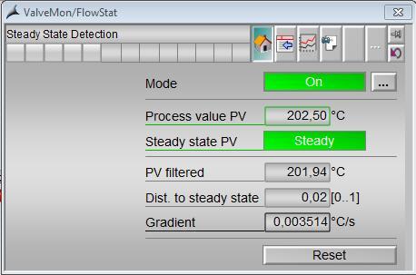
27 Detection of steady state with Calculation and display of evaluated data Online evaluation of dynamic signals on steady Display of evaluated results Current values Across the time sequences (trend) Relevant measured value: Analog process values PST AG All Rights Unrestricted / Siemens Reserved.
28 Detection of steady state with Application examples Monitoring of steady state: From the environment of process monitoring: The startup of steady processes is often characterized by fluctuating process variables. When these variables become steady, the process is in a steady state. Monitoring the steadiness of the relevant process variables therefore immediately indicates the end of the startup process. Example: End of the startup process of a pump when a steady flow is achieved. In the field of closed-loop and open-loop control: In batch processes, transition to the next basic operation in the recipe often depends on achieving certain process conditions. This situation can be indicated by the detection of the corresponding signal's steadiness. PST Example: A step sequence in the Sequential Function Chart (SFC) does not activate the agitator motor of a reactor for a fixed and possibly excessive period of time; instead, it stirs until the temperature in the reactor has a steady value.
29 Detection of steady state with Application example Monitoring of Instationarity: From the field of process monitoring: Continuous units can be monitored for proper steady-state operation. As soon as the relevant process variables of a unit begin to fluctuate, drift or fail, the operator is notified or countermeasures are taken automatically. Example: If the head temperature of a distillation column is unsteady, the operator is immediately alerted to intervene accordingly. Determination of the plant status: Depending on the plant status, messages and alarms can be activated, suppressed or hidden. In this way, alarm surges of transient irrelevant messages can be prevented. Example: Alarm messages from the lower-level controllers are suppressed in unsteady startup or product changeover phases. PST
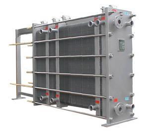
30 Monitoring of pressure loss with Application example: Target of monitoring the pressure loss of plant components like: Filters Separator Heat exchanger pipelines etc. in dependency on flow rate or in other words the monitoring of the flow resistance. Such a monitoring and early recognition can be reasonable for all plant components, whose flow resistance changes undesired during, e.g. Through caking Blockage etc. PST


31 Monitoring of pressure loss with Calculation and display through evaluation of data / operation states Display of pressure loss in dependence to flow rate and viscosity as set pressure loss characteristic line Display of current working point Display of current pressure loss characteristic line Current viscosity Current and relative deviation of characteristic lines PST Parametrization of differential pressure characteristic line Manual entering of specific values and supporting points Assumption of specific values and supporting points of current situation
 Inlet pressure (pressure before the valve) (2) Binar signal stationarity of inlet")
 Stationarity of viscosity (optional) PST The binar signals have to be provided")
32 Monitoring of pressure loss with Relevant measured values: Flow rate of the flowing medium (1) Binar signal stationarity of flow rate (1) Inlet pressure (pressure before the valve) (2) Binar signal stationarity of inlet pressure (2) Outlet pressure (pressure after the valve) (3) Binar signal stationarity of outlet pressure (3) Viscosity (optional if not constant) Stationarity of viscosity (optional) PST The binar signals have to be provided via separate moduls
 for pressures, flow rate and viscosity is reached.")
33 Monitoring of pressure loss with Calculation and display of pressure loss compared to flow rate Current characteristic line (1) depending on the viscosity with current working point. New measured points are recorded in case the stability () for pressures, flow rate and viscosity is reached. Set characteristic line (2) depending on the viscosity Display of current viscosity (3) within the 5 ranges 1 2 Display of Flow rate Differential pressure Viscosity (4) 4 3 PST Deviation 5 Relative deviation Display of exceeding the tolerance value (5)

34 Monitoring of pressure loss with Entering of specific values Choose viscosity range (5 ranges) (1) 1 The following characteristic lines can be stored via the faceplate: Differential pressure in relation to flow rate (2) 2 PST
35 Partial Stroke Test Introduction A Safety Instrumented Function (SIF) can be described as a function with which a specific Safety Integrity Level (SIL) is implemented with regard to a specific process risk. The SIL can be derived from the average Probability of Failure on Demand (PFD) for a SIF è a device does not perform the intended function when requested. The PFD-value of the safety integrated function is determined through the portion of undetected, dangerous failures and the interval between the manual Proof of the Safety integrated function Through common proofs of safety integrated function as well as reduction of undetected, dangerous failure (via redundancy, increased diagnosis) the PFD-value is improved PST
36 Partial Stroke Test Introduction In technical terms this means: Safety shutoff valves normally stay in just one position: fully open or fully closed: fully opened or fully closed è These safety valves only have to perform a movement in an emergency. The fact that they do not move for long periods of time can cause the valves to block under the tough plant conditions. Regular tests are therefore required to ensure that the valve is functioning correctly and is not blocked in an emergency situation. PST
37 Partial Stroke Test What does Partial Stroke Test mean? Partial closing of valve starting from the full opened position to proof the movement of the valve. In this test, the valve normally completes a stroke of 10-20% of the full stroke. The actual stroke value of the valve depends on factors such as valve types and size, the manufacturer's recommendations and the operating conditions. Proofing of valve, without restrictions on process or triggering a failure Does not cover up to 100% of all failures. PST Because the valve does not completely close, the complete way of the valve can not be proven or whether the valve closes tightly. è the PST covers 50% and more of failures depending on the device
38 Partial Stroke Test The most common error patterns in valve drive systems Fault description Solenoid valve not switching Possible cause of error Trip for the solenoid valve defective Partial Stroke Test Fault detectable? Full stroke/full rotation test Detectable Detectable Detection via feedback value Solenoid valve not switching Solenoid valve defective Detectable Detectable Detection via feedback value Valve reacts too slowly Air line to the valve is pinched Detectable Detectable Valve reacts too slowly Valve is sluggish Detectable Detectable Fault detection Detection by monitoring the time until feedback value is given Detection by monitoring the time until feedback value is given PST Valve does not close or does not close completely Valve seat pitted Disk eroded not detectable Detectable Detection not possible via Partial Stroke Test Valve does not close or does not close completely Valve set has deposits not detectable Detectable Detection not possible via Partial Stroke Test Valve does not close Valve stem blocked Detectable Detectable Detection via feedback value Source: NAMUR- NE106
39 Partial Stroke Test Using the Partial Stroke Test to achieve a higher SIL IEC SIL PST FST SIL 1 SIL 2 SIL 3 SIL 4 PFD(t) PST Interval = Safety Integrity Level = Partial Stroke Test = Full Stroke Test FST Interval PFD AVG PFD AVG Time (years) Without PST 1 year Proof Testing = SIL 1 With PST (4x/year) 1 year Proof Testing = SIL 2 PST
 PST Interval PFD AVG Without PST 1 year Proof Testing =")
 Time")
40 Partial Stroke Test Using the Partial Stroke Test to increase the Full Stroke Test interval IEC SIL 1 SIL 2 SIL 3 PFD(t) PST Interval PFD AVG Without PST 1 year Proof Testing = SIL 2 With PST (4x/year) 2 year Proof Testing = SIL 2 PST SIL 4 FST Interval SIL = Safety Integrity Level PST = Partial Stroke Test FST = Full Stroke Test (Full Proof Test) Time (years)
41 Partial Stroke Test Related blocks and functions To execute the Partial Stroke Test the following blocks and functions have been created: PST standard logic of the Partial Stroke Test (1) F_PST fail-safe logic of the Partial Stroke Test (2) F_PST_S optional fail-safe logic of the solenoid (3) valve test PST_OrQC Evaluation of signal status (4) F_PST_CALC PFD calculations to determine the time of the next Full Stroke Test (5) To simplify the Engineering a template is also delivered The template contains blocks of S7 F Systems/S7 F Library and of APL. Both libraries have to be installed before the PST to use functions PST
42 Partial Stroke Test : Functions Automatic performance of tests in specific intervals. Supports the performance in automatic or manual mode. Opportunity to interlock the function in case the PST is not allowed to be started caused by the plant Calculates the instant of time for the following Full Stroke Test is required. The PST includes messages about the valve s status (e.g. valve is blocked) Records the movement of the valve and provides this to record the operator. This permits the operator an overview on the state and possibly plans for further actions. Does not interfere into the part of the safety integrated function and stops the test in case of emergency A test is not performed, in case a Bypass or bad Signal Status is detected. Adjustable area of the Test- set value fluctuates to prevent depositions at the test position in the valve. Optional solenoid valves can be integrated. These valves are tested with delay after a successful PST. Detects test which are automatically initiated. Ensures that all tests are recorded. Temporal monitoring of tests with failure message if the time is exceeded PST
 Date Mode Display of following required Full Stroke Tests (3) 1 2 3")
43 Partial Stroke Test Overview Partial Stroke Test Data display of latest Partial Stroke Tests with (1) Date Result Test data Display of following planned Partial Stroke Tests with (2) Date Mode Display of following required Full Stroke Tests (3) PST

 1 3 Display of")
")
44 Partial Stroke Test Further view of PST Entering of parameter for Partial Stroke Test (1) Entering of parameter for solenoid valve test (2) 1 3 Display of current valve status and release conditions for Partial Stroke Test (3) Gradient limits (4) 2 PST 4
45 Partial Stroke Test Production of record Precast report layouts are also delivered (German/English) Automatic documentation of tests Store and/or print to archive Content of report: Solenoid valve test (1) PST Set value (2) Feedback (reaction) (3) Response time
46 Software and licenses Licensing of modules The software SIMATIC PCS 7 Condition Monitoring Library is available for V8.0 and V8.1 at no charge. Depending on the used module the following number of process objects (PO) "SIMATIC PCS 7 AS Runtime" and "SIMATIC PCS 7 OS Runtime" are recorded per module instance: : 20 PO : 10 PO : 2 PO PST: 30 PO PST : 20 PO
47 Informations Homepage SIMATIC PCS 7 technical library technologies/technology_libraries/pages/technology-libraries.aspx Homepage SIMATIC PCS 7 Maintenance Station system-components/maintenance-station/pages/maintenance-station.aspx Sales and delivery release PCS 7 Condition Monitoring Library V8.0 and Download Sales and delivery release PCS 7 Condition Monitoring Library V8.0 + SP1 and Download Sales and delivery release PCS 7 Condition Monitoring Library V8.1 and Download Tbd Whitepaper Asset Management mechanical plant components with SIMATIC PCS 7 PST system-components/maintenance-station/documents/whitepapermechanicalassets_en_2014.pdf
48 ReMain Research Project Reliability Centered Maintenance (ReMain) Reliable diagnostics of remaining life-time of pumps Optimization of pump maintenance Optimization of pump operation Continuous monitoring and analysis of over 100 pumps in a production plant operated by Evonik-Degussa resp. Stockhausen in the chemical park in Marl over 2 years of operation delivers for the first time a broad data base as a basis for transferable results PST
 595-2748 Cellular: +49 (173) 9931279 E-Mail: jan-henning.andresen@siemens.com siemens.")
49 Thank you for your attention! Jan-Henning Andresen Product Manager I IA AS PA PRM 1 Ostliche Rheinbrueckenstr Karlsruhe Phone: +49 (721) Cellular: +49 (173) jan-henning.andresen@siemens.com siemens.com/answers
Series 3730 and Series 3731 EXPERTplus Valve Diagnostics with Partial Stroke Test (PST)
") Series 3730 and Series 3731 EXPERTplus Valve Diagnostics with Partial Stroke Test (PST) Application Positioner firmware for early detection of control valve faults giving maintenance recommendations. Valid
Series 3730 and Series 3731 EXPERTplus Valve Diagnostics with Partial Stroke Test (PST) Application Positioner firmware for early detection of control valve faults giving maintenance recommendations. Valid
Positioner type Smart Valve Positioner with diagnostic functions. Presented By: Mr. Gourishankar Saharan. Product management Jens Bargon / V42
 Positioner type 3730-5 Smart Valve Positioner with diagnostic functions Presented By: Mr. Gourishankar Saharan Product management Jens Bargon / V42 Product overview P Process V Valves l Control Valves
Data Sheet T 8389 EN. Series 3730 and 3731 Types , , , and. EXPERTplus Valve Diagnostic
 Data Sheet T 8389 EN Series 3730 and 3731 Types 3730-2, 3730-3, 3730-4, 3730-5 and Type 3731-3 Electropneumatic Positioners EXPERTplus Valve Diagnostic Application Positioner firmware to detect potential
Safety Manual. Process pressure transmitter IPT-1* 4 20 ma/hart. Process pressure transmitter IPT-1*
 Safety Manual Process pressure transmitter IPT-1* 4 20 ma/hart Process pressure transmitter IPT-1* Contents Contents 1 Functional safety 1.1 General information... 3 1.2 Planning... 4 1.3 Instrument parameter
Safety Manual VEGAVIB series 60
 Safety Manual VEGAVIB series 60 NAMUR Document ID: 32005 Contents Contents 1 Functional safety... 3 1.1 General information... 3 1.2 Planning... 4 1.3 Adjustment instructions... 6 1.4 Setup... 6 1.5 Reaction
2600T Series Pressure Transmitters Plugged Impulse Line Detection Diagnostic. Pressure Measurement Engineered solutions for all applications
 Application Description AG/266PILD-EN Rev. C 2600T Series Pressure Transmitters Plugged Impulse Line Detection Diagnostic Pressure Measurement Engineered solutions for all applications Increase plant productivity
Safety Manual VEGAVIB series 60
 Safety Manual VEGAVIB series 60 Contactless electronic switch Document ID: 32002 Contents Contents 1 Functional safety... 3 1.1 General information... 3 1.2 Planning... 4 1.3 Adjustment instructions...
Monitoring and Diagnostics of Control Valves using the VlvMon Function Block in SIMATIC PCS 7
 Application description 02/2014 Monitoring and Diagnostics of Control Valves using the VlvMon Function Block in SIMATIC PCS 7 SIMATIC PCS 7 Condition Monitoring Library http://support.automation.siemens.com/ww/view/en/87604493
Safety Manual OPTISWITCH series relay (DPDT)
") Safety Manual OPTISWITCH series 5000 - relay (DPDT) 1 Content Content 1 Functional safety 1.1 In general................................ 3 1.2 Planning................................. 5 1.3 Adjustment
Safety Manual OPTISWITCH series 5000 - relay (DPDT) 1 Content Content 1 Functional safety 1.1 In general................................ 3 1.2 Planning................................. 5 1.3 Adjustment
Valve Communication Solutions. Safety instrumented systems
 Safety instrumented systems Safety Instrumented System (SIS) is implemented as part of a risk reduction strategy. The primary focus is to prevent catastrophic accidents resulting from abnormal operation.
Life Cycle Benefits: Maintenace (Control Valve Diagnostic and Field Device Diagnostic Management)
") Life Cycle Benefits: Maintenace (Control Valve Diagnostic and Field Device Diagnostic Management) Yasushi Kudo Yamatake Corporation Aaron Chen Azbil Taiwan Contents I. Prologue II. Possibilities of CV
Life Cycle Benefits: Maintenace (Control Valve Diagnostic and Field Device Diagnostic Management) Yasushi Kudo Yamatake Corporation Aaron Chen Azbil Taiwan Contents I. Prologue II. Possibilities of CV
Neles ValvGuard VG9000H Rev 2.0. Safety Manual
 Neles ValvGuard VG9000H Rev 2.0 Safety Manual 10SM VG9000H en 11/2016 2 Neles ValvGuard VG9000H Rev 2.0 Safety Manual Table of Contents 1 General information...3 1.1 Purpose of the document... 3 1.2 Description
Neles trunnion mounted ball valve Series D Rev. 2. Safety Manual
 Neles trunnion mounted ball valve Series D Rev. 2 Safety Manual 10SM D en 1/2017 2 Neles trunnion mounted ball valve, Series D Table of Contents 1 Introduction...3 2 Structure of the D series trunnion
Courses of Instruction: Controlling and Monitoring of Pipelines
 Courses of Instruction: Controlling and Monitoring of Pipelines Date December 2010 Dr. Peter Eschenbacher Partner Angergraben 4 85250 Altomünster Germany Tel. +49-(0)8254 / 99 69 57 Fax +49-(0)8254 / 99
Valve Communication Solutions Axiom
 Axiom Detect automated valve problems... before they shut down your process Reasons for Automated On/Off Valve Failures Monitor Fail Solenoid Fail Actuator Fail Coupling Break Too Slow Leaking Sticking
Solenoid Valves used in Safety Instrumented Systems
 I&M V9629R1 Solenoid Valves used in Safety Instrumented Systems Operating Manual in accordance with IEC 61508 ASCO Valves Page 1 of 7 Table of Contents 1 Introduction...3 1.1 Terms and Abbreviations...3
PREDICTING HEALTH OF FINAL CONTROL ELEMENT OF SAFETY INSTRUMENTED SYSTEM BY DIGITAL VALVE CONTROLLER
 PREDICTING HEALTH OF FINAL CONTROL ELEMENT OF SAFETY INSTRUMENTED SYSTEM BY DIGITAL VALVE CONTROLLER Riyaz Ali FIELDVUE Business Development Manager Fisher Controls Int'l., LLC. Marshalltown, IA 50158
RESILIENT SEATED BUTTERFLY VALVES FUNCTIONAL SAFETY MANUAL
 Per IEC 61508 and IEC 61511 Standards BRAY.COM Table of Contents 1.0 Introduction.................................................... 1 1.1 Terms and Abbreviations...........................................
2600T Series Pressure Transmitter Models 264DC Differential and 264HC Gage Level Transmitters. Kent-Taylor
 INDUSTRIAL INSTRUMENTS AND CONTROLS SPECIALIST Kent-Taylor 2600T Series Pressure Transmitter Models 264DC Differential and 264HC Gage Level Transmitters Features Include Base accuracy : ±0.075% Span limits
USER MANUAL. Intelligent Diagnostic Controller IDC24-A IDC24-AF IDC24-AFL IDC24-F IDP24-A * IDP24-AF * IDP24-AFL * IDP24-F * 1/73
 USER MANUAL Intelligent Diagnostic Controller IDC24-A IDC24-AF IDC24-AFL IDC24-F IDP24-A * IDP24-AF * IDP24-AFL * IDP24-F * *) Require software ID: DID-SW-001 1/73 Table of contents 1 General... 3 1.1
1. Functional description. Application program usage. 1.1 General. 1.2 Behavior on bus voltage loss and bus voltage. 1.
 Application program usage product family: Product type: Manufacturer: Name: Order-No.: Valve actuators Constant valve actuator Siemens Valve actuator AP 562/02 5WG1 562-7AB02 Commissioning For commissioning
Control & Maintenance. INT69 Diagnose INT69 TM Diagnose. Protect the heart of your system
 Control & Maintenance INT69 Diagnose INT69 TM Diagnose Protect the heart of your system R INT69 DIAGNOSE The widely known protective system INT69 and INT69 TM present on all Frascold compressors is now
The Future of Hydraulic Control in Water-Systems
 The Future of Hydraulic Control in Water-Systems A. Heimann Manager of R&D and of Technical Support & Applications Engineering departments at Dorot Automatic Control Valves Dorot Control Valves, Kibbutz
Operating Instructions EB EN. Series 373x Electropneumatic Positioner Type 373x-5 EXPERT + with FOUNDATION fieldbus communication
 Series 373x Electropneumatic Positioner Type 373x-5 EXPERT + with FOUNDATION fieldbus communication Fig. 1 Valve diagnostics with TROVIS-VIEW Operator Interface Operating Instructions EB 8388-5 EN Firmware
Special Documentation Proline Promass 80, 83
 SD00077D/06/EN/14.14 71272498 Products Solutions Services Special Documentation Proline Promass 80, 83 Functional safety manual Coriolis mass flow measuring system with 4 20 ma output signal Application
Partial Stroke Testing for SRD991 and SRD960
 Technical Information 09.11 TI EVE0105 PST-(en) Partial Stroke Testing for SRD991 and SRD960 Final control elements in Emergency Shutdown (ESD) applications such as ON-OFF-, Blow Down and Venting-Valves
Reliability of Safety-Critical Systems Chapter 3. Failures and Failure Analysis
 Reliability of Safety-Critical Systems Chapter 3. Failures and Failure Analysis Mary Ann Lundteigen and Marvin Rausand mary.a.lundteigen@ntnu.no RAMS Group Department of Production and Quality Engineering
High performance disc valves Series Type BA, BK, BW, BM, BN, BO, BE, BH Rev Safety Manual
 High performance disc valves Series Type BA, BK, BW, BM, BN, BO, BE, BH Rev. 2.0 Safety Manual 10SM B Disc en 4/2018 2 High performance disc valves Series, Type BA, BK, BW, BM, BN, BO, BE, BH, Rev. 2.0
The benefits of the extended diagnostics feature. Compact, well-proven, and flexible
 ABB MEASUREMENT & ANALYTICS TECHNICAL INFORMATION PositionMaster EDP300 Extended Diagnostics Compact, well-proven, and flexible The benefits of the extended diagnostics feature The PositionMaster EDP300
Jamesbury Pneumatic Rack and Pinion Actuator
 Jamesbury Pneumatic Rack and Pinion Actuator Valv-Powr Series VPVL Rev. 3.0 Safety Manual 10SM VPVL en 5/2017 2 Jamesbury Pneumatic Rack and Pinion Actuator, Valv-Powr Series VPVL, Rev 3.0, Safety Manual
Ultima. X Series Gas Monitor
 Ultima X Series Gas Monitor Safety Manual SIL 2 Certified " The Ultima X Series Gas Monitor is qualified as an SIL 2 device under IEC 61508 and must be installed, used, and maintained in accordance with
Session One: A Practical Approach to Managing Safety Critical Equipment and Systems in Process Plants
 Session One: A Practical Approach to Managing Safety Critical Equipment and Systems in Process Plants Tahir Rafique Lead Electrical and Instruments Engineer: Qenos Botany Site Douglas Lloyd Senior Electrical
MARKET OUTLOOK. Power Chemicals Petroleum Water/Wastewater Oil & Gas Pulp & Paper and more
 FALL 2004 VOLUME 16, NO. 4 2005 MARKET OUTLOOK Power Chemicals Petroleum Water/Wastewater Oil & Gas Pulp & Paper and more PLUS: Powerful Products for the Power Industry Valves in Bioprocessing Smart Control
SIL Safety Manual. ULTRAMAT 6 Gas Analyzer for the Determination of IR-Absorbing Gases. Supplement to instruction manual ULTRAMAT 6 and OXYMAT 6
 ULTRAMAT 6 Gas Analyzer for the Determination of IR-Absorbing Gases SIL Safety Manual Supplement to instruction manual ULTRAMAT 6 and OXYMAT 6 ULTRAMAT 6F 7MB2111, 7MB2117, 7MB2112, 7MB2118 ULTRAMAT 6E
Competence in Functional Safety
 MANUAL Competence in Functional Safety Safety-instrumented system Instrumentation Automation SMART IN FLOW CONTROL. SAMSON AIR TORQUE CERA SYSTEM KT-ELEKTRONIK LEUSCH PFEIFFER RINGO SAMSOMATIC STARLINE
Partial Stroke Testing. A.F.M. Prins
 Partial Stroke Testing A.F.M. Prins Partial Stroke Testing PST in a safety related system. As a supplier we have a responsibility to our clients. What do they want, and what do they really need? I like
DeZURIK. KGC Cast Knife Gate Valve. Safety Manual
 KGC Cast Knife Gate Valve Safety Manual Manual D11036 August 29, 2014 Table of Contents 1 Introduction... 3 1.1 Terms... 3 1.2 Abbreviations... 4 1.3 Product Support... 4 1.4 Related Literature... 4 1.5
Service Test Unit for ROSS Proportional Valves RESK
 Service Unit for Proportional Valves Page 1 Technical Description ROSS 04.08.2015 Service Test Unit for ROSS Proportional Valves Technical Description V 1.0 / 2015 RESK 4591.40 For all Prop Valve Models
PositionMaster EDP300 Extended Diagnostics. Compact, well-proven, and flexible
 Change from one to two columns Technical Information TI/EDP300_ED-EN Rev. A PositionMaster EDP300 Extended Diagnostics Compact, well-proven, and flexible The benefits of the extended diagnostics feature
MECHANICAL EQUIPMENTS: COMPRESSORS, PUMPS, SEALS, SPEED DRIVES, CONTROL VALVES & ACTUATORS & SAFETY RELIEF VALVES
 Training Title MECHANICAL EQUIPMENTS: COMPRESSORS, PUMPS, SEALS, SPEED DRIVES, CONTROL VALVES & ACTUATORS & SAFETY RELIEF VALVES Training Duration 5 days Training Venue and Dates REF Mechanical Equipments:
High Integrity Pressure Protection Systems HIPPS
 High Integrity Pressure Protection Systems HIPPS HIPPS > High Integrity Pressure Protection Systems WHAT IS A HIPPS The High Integrity Pressure Protection Systems (HIPPS) is a mechanical and electrical
Technical Data Sheet MF010-O-LC
 Technical Data Sheet MF010-O-LC - 1 - 1. Properties The oxygen measuring system MF010-O-LC determines the oxygen content in gas mixtures up to a temperature of 250 C. It is particularly suitable for the
FUEL GAS FIRING CONTROL RJ (Dick) Perry Safety Systems Consultant 6 June 2016
 Perry Safety Systems Consultant 6 June 2016") INTRODUCTION Fired equipment such as Heaters and Boilers, normally have to comply with either NFPA 85/86 or API 556 for North America and some other countries which apply such standards, or EN 746-2 for
INTRODUCTION Fired equipment such as Heaters and Boilers, normally have to comply with either NFPA 85/86 or API 556 for North America and some other countries which apply such standards, or EN 746-2 for
Control. Internal and master controllers. Types of internal control
 Control Controls in compressor systems are used for both compressed air production and compressed air treatment. This fact sheet deals with the controls which match compressed air production to consumption
Advanced Pump Control for Irrigation Applications
 Advanced Pump Control for Irrigation Applications Paul Nistler VFD Applications Engineer And Julian Atchia Director of Research and Development SJE Rhombus 22650 County Hwy 6 Detroit Lakes MN 56502 Executive
Reliable, low-maintenance pressure measurement with SITRANS P
 Processes require precision Reliable, low-maintenance pressure measurement with SITRANS P www.usa.siemens.com/pressure Pressure measurement under control It s impossible to imagine today s process industries
Failure Modes, Effects and Diagnostic Analysis
 Failure Modes, Effects and Diagnostic Analysis Project: Solenoid Drivers KFD2-SL2-(Ex)1.LK.vvcc KFD2-SL2-(Ex)*(.B).vvcc Customer: Pepperl+Fuchs GmbH Mannheim Germany Contract No.: P+F 06/09-23 Report No.:
RICK FAUSEL, BUSINESS DEVELOPMENT ENGINEER TURBOMACHINERY CONTROL SYSTEM DESIGN OBJECTIVES
 RICK FAUL, BUSINESS DEVELOPMENT ENGINEER TURBOMACHINERY CONTROL SYSTEM DESIGN OBJECTIVES The primary design objective for any turbomachinery control system should be to maintain or maximize machine and
V10K GAS FEED SYSTEM WALLACE & TIERNAN PRODUCTS
 V10K GAS FEED SYSTEM WALLACE & TIERNAN PRODUCTS V10K SYSTEM: PROVEN TECHNOLOGY WORLDWIDE IN USE Since Charles F. Wallace and Martin F. Tiernan discovered the first chlorine gas feed system in 1913 the
Service & Support. Questions and Answers about the Proof Test Interval. Proof Test According to IEC FAQ August Answers for industry.
 Cover sheet Questions and Answers about the Proof Test Interval Proof Test According to IEC 62061 FAQ August 2012 Service & Support Answers for industry. Contents This entry originates from the Siemens
Understanding safety life cycles
 Understanding safety life cycles IEC/EN 61508 is the basis for the specification, design, and operation of safety instrumented systems (SIS) Fast Forward: IEC/EN 61508 standards need to be implemented
Section 1: Multiple Choice
 CFSP Process Applications Section 1: Multiple Choice EXAMPLE Candidate Exam Number (No Name): Please write down your name in the above provided space. Only one answer is correct. Please circle only the
Multiple Pressure Booster Systems With Variable Speed Controller Type BL
 Multiple Pressure Booster Systems With Variable Speed Controller Type BL General Characteristics - Single or multistage pumps - Horizontal or vertical mounting - Total head 30m ~ 250m - Material construction:
Eutectic Plug Valve. SIL Safety Manual. SIL SM.015 Rev 0. Compiled By : G. Elliott, Date: 19/10/2016. Innovative and Reliable Valve & Pump Solutions
 SIL SM.015 Rev 0 Eutectic Plug Valve Compiled By : G. Elliott, Date: 19/10/2016 Contents Terminology Definitions......3 Acronyms & Abbreviations...4 1. Introduction..5 1.1 Scope 5 1.2 Relevant Standards
KIT. Small Automatic Water Boosters KIT MODELS
 KIT Small Automatic Water Boosters The electronic controller KIT orders the automatic start and stop of the water pump when opening or closing any tap or valve in the installation. There are four main
Hydraulic (Subsea) Shuttle Valves
 Shuttle Valves") SIL SM.009 0 Hydraulic (Subsea) Shuttle Valves Compiled By : G. Elliott, Date: 11/3/2014 Contents Terminology Definitions......3 Acronyms & Abbreviations..4 1. Introduction 5 1.1 Scope 5 1.2 Relevant Standards
SIL SM.009 0 Hydraulic (Subsea) Shuttle Valves Compiled By : G. Elliott, Date: 11/3/2014 Contents Terminology Definitions......3 Acronyms & Abbreviations..4 1. Introduction 5 1.1 Scope 5 1.2 Relevant Standards
Specifications and information are subject to change without notice. Up-to-date address information is available on our website.
 www.smar.com Specifications and information are subject to change without notice. Up-to-date address information is available on our website. web: www.smar.com/contactus.asp FY302 AssetView IHM FY302 -
Transmitter CS 21 Operation Manual
 Transmitter CS 21 Operation Manual Content Page For your Safety 3 General Description 3 Detection Principle 4 Operational Notes 4 Design 4 Mounting Position of CS21 5 Mounting 6 Installation of Electrical
L&T Valves Limited SAFETY INTEGRITY LEVEL (SIL) VERIFICATION FOR HIGH INTEGRITY PRESSURE PROTECTION SYSTEM (HIPPS) Report No.
 VERIFICATION FOR HIGH INTEGRITY PRESSURE PROTECTION SYSTEM (HIPPS) Report No.") L&T Valves Limited TAMIL NADU SAFETY INTEGRITY LEVEL (SIL) VERIFICATION FOR HIGH INTEGRITY PRESSURE PROTECTION SYSTEM (HIPPS) MAY 2016 Report No. 8113245702-100-01 Submitted to L&T Valves Ltd. Report by
L&T Valves Limited TAMIL NADU SAFETY INTEGRITY LEVEL (SIL) VERIFICATION FOR HIGH INTEGRITY PRESSURE PROTECTION SYSTEM (HIPPS) MAY 2016 Report No. 8113245702-100-01 Submitted to L&T Valves Ltd. Report by
This portion of the piping tutorial covers control valve sizing, control valves, and the use of nodes.
 Piping Tutorial A piping network represents the flow of fluids through several pieces of equipment. If sufficient variables (flow rate and pressure) are specified on the piping network, CHEMCAD calculates
H250 M9 Supplementary instructions
 H250 M9 Supplementary instructions Variable area flowmeter Safety manual acc. to IEC 61508:2010 KROHNE CONTENTS H250 M9 1 Introduction 3 1.1 Fields of application... 3 1.2 User benefits... 3 1.3 Relevant
Application of CHE100 in Frequency Conversion Alteration of Air Compressor System
 Application of CHE100 in Frequency Conversion Alteration of Air Compressor System Abstract: This paper describes application of CHE100 in frequency conversion alteration of the air compressor system and
PIG MOTION AND DYNAMICS IN COMPLEX GAS NETWORKS. Dr Aidan O Donoghue, Pipeline Research Limited, Glasgow
 PIG MOTION AND DYNAMICS IN COMPLEX GAS NETWORKS Dr Aidan O Donoghue, Pipeline Research Limited, Glasgow A model to examine pigging and inspection of gas networks with multiple pipelines, connections and
Reliability of Safety-Critical Systems Chapter 4. Testing and Maintenance
 Reliability of Safety-Critical Systems Chapter 4. Testing and Maintenance Mary Ann Lundteigen and Marvin Rausand mary.a.lundteigen@ntnu.no RAMS Group Department of Production and Quality Engineering NTNU
Analysis of Instrumentation Failure Data
 Analysis of Instrumentation Failure Data A structured approach Standards Certification Education & Training Publishing Conferences & Exhibits Matthew F. (Matt) Murphy Senior Consultant, DuPont Engineering
TRI LOK SAFETY MANUAL TRI LOK TRIPLE OFFSET BUTTERFLY VALVE. The High Performance Company
 TRI LOK TRI LOK TRIPLE OFFSET BUTTERFLY VALVE SAFETY MANUAL The High Performance Company Table of Contents 1.0 Introduction...1 1.1 Terms and Abbreviations... 1 1.2 Acronyms... 1 1.3 Product Support...
A4s Operation Manual
 A4s Operation Manual Safety Instruction Please read this manual carefully, also with related manual for the machinery before use the controller. For installing and operating the controller properly and
Training Fees 3,400 US$ per participant for Public Training includes Materials/Handouts, tea/coffee breaks, refreshments & Buffet Lunch.
 Training Title DISTRIBUTED CONTROL SYSTEMS (DCS) 5 days Training Venue and Dates DISTRIBUTED CONTROL SYSTEMS (DCS) Trainings will be conducted in any of the 5 star hotels. 5 22-26 Oct. 2017 $3400 Dubai,
DeZURIK. KSV Knife Gate Valve. Safety Manual
 KSV Knife Gate Valve Safety Manual Manual D11035 August 29, 2014 Table of Contents 1 Introduction... 3 1.1 Terms... 3 1.2 Abbreviations... 4 1.3 Product Support... 4 1.4 Related Literature... 4 1.5 Reference
Advanced Test Equipment Rentals ATEC (2832) OMS 600
 OMS 600") Established 1981 Advanced Test Equipment Rentals www.atecorp.com 800-404-ATEC (2832) OMS 600 Continuous partial discharge monitoring system for power generators and electrical motors Condition monitoring
Established 1981 Advanced Test Equipment Rentals www.atecorp.com 800-404-ATEC (2832) OMS 600 Continuous partial discharge monitoring system for power generators and electrical motors Condition monitoring
Every things under control High-Integrity Pressure Protection System (HIPPS)
") Every things under control www.adico.co info@adico.co Table Of Contents 1. Introduction... 2 2. Standards... 3 3. HIPPS vs Emergency Shut Down... 4 4. Safety Requirement Specification... 4 5. Device Integrity
Every things under control www.adico.co info@adico.co Table Of Contents 1. Introduction... 2 2. Standards... 3 3. HIPPS vs Emergency Shut Down... 4 4. Safety Requirement Specification... 4 5. Device Integrity
Table 1: Safety Function (SF) Descriptions
 Descriptions") Table 1: Safety Function (SF) Descriptions NOTE: all safety s are individual safety s TUV NORD? Pressing the Estop PB on the pendant 1 or the Estop (if using the Estop Safety Input configured for Estop)
Table 1: Safety Function (SF) Descriptions NOTE: all safety s are individual safety s TUV NORD? Pressing the Estop PB on the pendant 1 or the Estop (if using the Estop Safety Input configured for Estop)
A4 Operation Manual. Fig.1-1 Controller Socket Diagram
 A4 Operation Manual Safety Instruction Please read this manual carefully, also with related manual for the machinery before use the controller. For installing and operating the controller properly and
Instrumented Safety Systems
 Instrumented Safety Systems Engineered Valve Systems for Control and Safety Applications HIPPS Final Elements DINO OLIVIERI Mokveld Agent AIS ISA Giornata di studio HIPPS Agenda The loop Final Elements
Hazard Operability Analysis
 Hazard Operability Analysis Politecnico di Milano Dipartimento di Energia HAZOP Qualitative Deductive (search for causes) Inductive (consequence analysis) AIM: Identification of possible process anomalies
Pneumatic QEV. SIL Safety Manual SIL SM Compiled By : G. Elliott, Date: 8/19/2015. Innovative and Reliable Valve & Pump Solutions
 SIL SM.0010 1 Pneumatic QEV Compiled By : G. Elliott, Date: 8/19/2015 Contents Terminology Definitions......3 Acronyms & Abbreviations..4 1. Introduction 5 1.1 Scope 5 1.2 Relevant Standards 5 1.3 Other
Characterizers for control loops
 Characterizers for control loops By: F. G. Shinskey (May 1999) Introduction Commercial controllers such as the PID series (proportional, integral, derivative, and their combinations) are linear devices
HIGH FLOW PROTECTION FOR VARIABLE SPEED PUMPS
 Proceedings of the First Middle East Turbomachinery Symposium February 13-16, 2011, Doha, Qatar HIGH FLOW PROTECTION FOR VARIABLE SPEED PUMPS Amer A. Al-Dhafiri Rotating Equipment Engineer Nabeel M. Al-Odan
SPECIAL PRINT. Innovative Control Technology. Safety in the Process Industry. SAMSON AG Manuel Hinkelmann Marcel Richter Monika Schneider
 Innovative Control Technology SPECIAL PRINT Safety in the Process Industry SAMSON AG Manuel Hinkelmann Marcel Richter Monika Schneider SAMSOMATIC Marc Belzer Translation of special print from: cav 6-2014,
Considering Control Valve EFFICIENCY
 Considering Control Valve EFFICIENCY Strategies for optimizing the energy requirement for control valves in plant systems The discussions revolving around the scarcity of fossil fuels and increasing energy
Roller AC Servo System
 Safely Instruction Roller AC Servo System HMI-15 User Manual Please read this manual carefully, also with related manual for the machinery before use the controller. For installing and operating the controller
SIL explained. Understanding the use of valve actuators in SIL rated safety instrumented systems ACTUATION
 SIL explained Understanding the use of valve actuators in SIL rated safety instrumented systems The requirement for Safety Integrity Level (SIL) equipment can be complicated and confusing. In this document,
CSO/STORMWATER MANAGEMENT. HYDROVEX HHV-E Vortex Driven Regulator
 CSO/STORMWATER MANAGEMENT HYDROVEX HHV-E Vortex Driven Regulator HYDROVEX HHV-E VORTEX DRIVEN REGULATOR APPLICATION The hydro electronic HYDROVEX HHV driven regulator, type E is specially designed for
DeZURIK Double Block & Bleed (DBB) Knife Gate Valve Safety Manual
 Knife Gate Valve Safety Manual") Double Block & Bleed (DBB) Knife Gate Valve Safety Manual Manual D11044 September, 2015 Table of Contents 1 Introduction... 3 1.1 Terms... 3 1.2 Abbreviations... 4 1.3 Product Support... 4 1.4 Related
Double Block & Bleed (DBB) Knife Gate Valve Safety Manual Manual D11044 September, 2015 Table of Contents 1 Introduction... 3 1.1 Terms... 3 1.2 Abbreviations... 4 1.3 Product Support... 4 1.4 Related
Bespoke Hydraulic Manifold Assembly
 SIL SM.0003 1 Bespoke Hydraulic Manifold Assembly Compiled By : G. Elliott, Date: 12/17/2015 Contents Terminology Definitions......3 Acronyms & Abbreviations..4 1. Introduction 5 1.1 Scope 5 1.2 Relevant
Section 1: Multiple Choice Explained EXAMPLE
 CFSP Process Applications Section 1: Multiple Choice Explained EXAMPLE Candidate Exam Number (No Name): Please write down your name in the above provided space. Only one answer is correct. Please circle
AHE58/59 AC Servo System
 AHE58/59 AC Servo System HMI-12 User Manual Safely INstruction Please read this manual carefully, also with related manual for the machine head before use. For perfect operation and safety, installing
FLUID POWER FLUID POWER EQUIPMENT TUTORIAL OTHER FLUID POWER VALVES. This work covers part of outcome 2 of the Edexcel standard module:
 FLUID POWER FLUID POWER EQUIPMENT TUTORIAL OTHER FLUID POWER VALVES This work covers part of outcome 2 of the Edexcel standard module: UNIT 21746P APPLIED PNEUMATICS AND HYDRAULICS The material needed
The Univentor 1250 Anaesthesia Unit
 THE UNIVENTOR 1200/1250 ANAESTHESIA UNIT The Univentor 1250 Anaesthesia Unit TABLE OF CONTENTS EDITION 1 Section 1 - WARRANTY & SERVICE 1.1. WARRANTY 2 1.2. DAMAGED SHIPMENTS 2 1.3. SERVICE 2 Section 2
Yokogawa Systems and PCI Training
 Yokogawa Systems and PCI Training 09 th December 2014 Nico Marneweck 082 883 2652 Kallie Bodenstein 083 226 2787 Marco Coccioni 072 409 5779-1 - Introduction Training customised for the South Africa Industrial
FP15 Interface Valve. SIL Safety Manual. SIL SM.018 Rev 1. Compiled By : G. Elliott, Date: 30/10/2017. Innovative and Reliable Valve & Pump Solutions
 SIL SM.018 Rev 1 FP15 Interface Valve Compiled By : G. Elliott, Date: 30/10/2017 FP15/L1 FP15/H1 Contents Terminology Definitions......3 Acronyms & Abbreviations...4 1. Introduction...5 1.1 Scope.. 5 1.2
Transmitter CS 21 Operation Manual
 Transmitter CS 21 Operation Manual 1194 Oak Valley Drive, Suite 20, Ann Arbor, MI 48108 800-959-0573 734-769-1888 Content Page For your Safety 3 General Description 3 Detection Principle 4 Operation 4
Industrial Compressor Controls Standard Custom
 Technical Seminars 2012 Industrial Compressor Controls Standard Custom CONTROLLING the power of ENERGY 1 TM 2 Woodward Compressor Controls Small Steam Turbine Driven Compressors (ITCC) 3 Simple Compressor
Technical Bulletin 0812-BE/BSA
 Technical Bulletin 0812-BE/BSA RF Valves mission is to solve valve problems. We achieve this by providing valves that offer the lowest cost of ownership and operation, highest reliability and minimum maintenance.
EL-O-Matic E and P Series Pneumatic Actuator SIL Safety Manual
 SIL Safety Manual DOC.SILM.EEP.EN Rev. 0 April 2017 EL-O-Matic E and P Series Pneumatic Actuator SIL Safety Manual schaal 1:1 EL Matic TM EL-O-Matic E and P Series DOC.SILM.EEP.EN Rev. 0 Table of Contents
Application Notes. SLP85xD Load Cells
 Application Notes Load Cells Table of Contents 1 Introduction 3 2 Description of the Filling Cycle 4 3 Filling Optimization 7 4 Filling Monitor 8 4.1 Weight-Based Filling Monitor... 8 4.2 Time-Based Filling
Proof Testing A key performance indicator for designers and end users of Safety Instrumented Systems
 Proof Testing A key performance indicator for designers and end users of Safety Instrumented Systems EUR ING David Green BEng(hons) CEng MIET MInstMC RFSE Ron Bell OBE BSc CEng FIET Engineering Safety
A Complete Solution For HIPPS
 A Complete Solution For HIPPS Are You Also Facing These Challenges For Your HIPPS? PERFORMANCE Test and Working procedures / Safety Life Cycle ENVIRONMENT Fugitive Emissions / Reduce or Eliminate Flares
Operating instructions Electrical switching facility pco
 Operating instructions Electrical switching facility pco from software version V1.33 on TABLE OF CONTENTS 1. Before you start... 4 1.1 Brief description... 4 1.2 Using this manual... 4 2. pco integrated
New Thinking in Control Reliability
 Doug Nix, A.Sc.T. Compliance InSight Consulting Inc. New Thinking in Control Reliability Or Your Next Big Headache www.machinerysafety101.com (519) 729-5704 Control Reliability Burning Questions from the