MULTI-DIAMETER, BI-DIRECTIONAL PIGGING FOR PIPELINE PRE-COMMISSIONING
|
|
|
- Joy Patrick
- 6 years ago
- Views:
Transcription
1 MULTI-DIAMETER, BI-DIRECTIONAL PIGGING FOR PIPELINE PRE-COMMISSIONING By: Magne Andreas Vik, StatoilHydro; Alf Åge Kristiansen, StatoilHydro Simon Sykes, FTL Seals Technology; Steve Hutcheson, Pipeline Pigging Technology and Aidan O Donoghue, Pipeline Research Limited. This paper examines the issues associated with multi-diameter, bi-directional pigging specifically for pipeline pre-commissioning. The technique can be used to flood and subsequently dewater a pipeline without the need for temporary subsea traps. An example is the Alve Pipeline in Norway. This 16 km flow-line from the Norne Platform to the Alve Manifold includes 10 and 12 pipe sections. The line was flooded from Norne using the pig with oxygen scavenged seawater and then dewatered using Nitrogen and produced gas from the well. The pigs needed to have a high sealing efficiency since very low velocities were used to flood the line and in order to avoid hydrates on dewatering. Multi-diameter wheel pigs were employed with non-buckling disc type seals. This paper describes the design of the pigs and the seals to achieve the required functionality. The test facility and testing performed to verify the pig performance is also illustrated. Finally, an overview of the offshore pigging operation is provided. Introduction In order to flood and subsequently dewater the Alve flow line, a number of high seal, multi-diameter and bi-directional pigs were required. The pipeline contains several internal diameters from 10 to 12. Since no pigging from the Alve manifold was possible (no launcher), all operations needed to be performed from Norne FPSO. Four pigs spaced with MEG were launched from Norne with oxygen scavenged water, propelled through the pipeline and then stopped in position just upstream of the manifold. Before start-up of the pipeline and introduction of hydrocarbon gas, the pigs were required to be reversed with nitrogen and travel back through the pipeline, with no gas bypass, and be received back on Norne. Pressure was first raised to 50 bar with nitrogen for pigging and to 80 bar with hydrocarbons from topside to give back pressure for start up. A field schematic is shown in Figure 1. Initially it was considered to perform this operation without any pigs but after a number of studies, the hydrate risk was considered to be too great. The need for high seal pigs was identified. A number of additional scenarios for the operation were considered which impacted on pig design: - 1. Reversal of the pigs from the manifold, just before the inline isolation valve the risk is that the pig will travel too far and will not be reversible from the 5 inlet line (Pumping into the middle of the pig rather than upstream); 2. Reversal of the pigs from before the expansion spool. The implication is that the pig does not need to operate negotiate any bends in the large diameter line. The base case was the second option, but consideration needed to be given to the first option as a potential contingency. Testing would be performed to establish pig efficiency in all components including the 12 bends and to establish if the first pig in the train was reversible from the valve location. If this proved to be difficult then additional procedural steps would be taken to avoid the train reaching the manifold. A pig train consisting of four pigs with MEG separation was required. The main pipeline features were as follows: - 10 Vertical launcher; 10 topside piping at launcher, 257mm internal diameter; 10 topside and riser, 267mm internal diameter; 12 pipeline, 320mm internal diameter, 15.7 km in length; 12 tie in spools and manifold, 305mm internal diameter with 5D bends. The following Functional Requirements were discussed and agreed with the project: - The pigs must be fully bi-directional with high sealing ability in both directions; Low flow rates were expected, in the region of l/min resulting in a pig velocity of 0.03 m/s to 0.08 m/s. The pig must be able to operate at such low velocities;
2 Good seal efficiency and pig support/centralisation were required to ensure safe negotiation with minimum bypass through all components along the system. The risk of gas bypassing on return to Norne could result in hydrate formation; Ratio between pig flip differential pressure (pressure to flip the seals forward and cause them to fail) and running differential pressure to be at least 5:1; The drive differential pressure in all pipeline components was requested to be less than 7 bars; Pigs to be fitted with isotope holder for tracking purposes; Pig handling to be considered for vertical launch and receipt. The final aspect that needed to be considered as a contingency was the possibility of the pig travelling too far into the manifold and provision of a method of reversal from this location. This may mean that the pig straddled the manifold inlet used for driving the pig back to Norne. Pig selection The timescales for the project were relatively short with initial feasibility in August 2008 and required pig delivery in December This only allowed three months to establish concepts, perform detailed engineering, test to verify the pig functionality and provide four units for the operation. An initial feasibility study was undertaken with the aim of selecting a single pig type for development for this application. Several different types of multi-diameter pigs were considered for this duty: - 1. Traditional multi-diameter pig with slotted guides and various diameter seals; 2. Wheel pig or Varipig TM from FTL Seals Technology; 3. Paddle Pig from Pipeline Engineering; 4. Other approaches from other suppliers. It must be stressed that whilst multi-diameter pigs have been successfully developed and used on many occasions, the project was not aware of any projects which have developed a multi-diameter bidirectional pig and with such a high emphasis on sealing (i.e. no visible leakage in any pipeline component). The pros and cons of each technology was discussed and it was concluded that given the timescales, then the wheel pig would be the best choice with the highest possibility of success. On the other hand, it is noted that with more time, the other methods could also be made to work. No other pig was considered for this project from this point onwards. It is considered the best approach to concentrate all efforts on one chosen approach with a high probability of success rather than to dilute the effort by having several different competing pig prototypes which have lower chance of success and take up excessive testing time. Running a competition for pig development is considered inefficient in general and it is better to establish the base case in a feasibility phase and then develop this further. Pig design The pig mechanical design was performed by FTL Seals Technology with input and guidance from Pipeline Pigging Technology and Pipeline Research Limited. In addition, StatoilHydro ensured that the requirements from the project were communicated as soon as possible. This is especially important in a tight timescale project and where small changes to the operation philosophy can have significant implications on the pig design. This was managed effectively throughout the development. The outline concept pig design is shown in Figure 2. The pig consists of two wheel modules with interlinked suspension arms. The pig travels on the centreline of the pipe and so it is easier to specify seals that will provide a good sealing action. The spring force in the suspension units is greater than the weight of the pig and so if the pig drops below centreline, then the restoring force is greater. The geometry of the wheel arms provides a mechanical advantage which results in a flat force / deflection curve, i.e. the force require to deflect the arms does not increase significantly in smaller diameters. As a result, the load on the wheels and bearings remains at an acceptable and determinable level. For the Alve pig, these wheel units are facing each other with seals at either end. The pig is axisymmetrical in design which guarantees full bi-directionality, See Figure 3. It was decided early on that a single, non-buckling seal would be used for both line sizes (10 and 12 ). This is discussed in detail below.
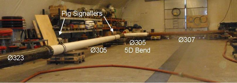
3 Detailed engineering on this concept followed and it became clear that in the event that the pig needed to travel through the 5D bends at the manifold, then there could be leakage past the pig. This is demonstrated in Figure 4. This is not acceptable for these Functional Requirements. To solve the problem an additional seal was introduced in the centre of the pig see Figure 5. Other issues associated with the layout of the pig include: - 1. Installation of an isotope holder. This is shown in Figure 6; 2. Provision of a lifting bar at the rear of the pig, see also Figure 6 the pig is loaded and removed from Norne as it is not handled subsea; 3. The front pig in the train was also a special, known as Type 1 Pig as this pig could potentially end up in the manifold and come to rest near the ball valve at the end of the manifold straddling the inlet line. This then required a slightly longer bumper nose to ensure that a seal was always downstream of the manifold off-take. The reversal of the pig from the manifold in the event of over-travel was subject to additional testing and modification as described later in this paper. Seal design The design of the seals for this pig was critical. One advantage of the wheel pig is that it supports the pig on the pipe centreline. The result is that, the seal diameter can be set just greater than the internal diameter of the largest bore and still provide a very good wiping action. Coupled with this, there has been good success lately with using a single disc seal to span several line sizes without buckling in the smallest size. This is known as the Single Seal concept. The idea is that a single oversized disc has the ability to work and provide a good seal at a range of smaller and smaller diameters before it finally buckles. The following scale of buckling has been investigated previously: - 1. No buckle; 2. Buckles when forced but recovers; 3. Buckles when forced but does not recover; 4. Buckles even when not forced to do so. To be safe, for this application, it is important that the seal does not buckle or if forced to do so, it returns to a full seal. Over the years much experience has been gained on buckling and non-buckling of seals for dual and multi-diameter pigging. Figure 7 shows some examples of where the large diameter seals are intentionally buckled into the small diameter line in order to allow smaller diameter seals to take over. This has been used to good effect in large diameter change projects where Buckle Inducers are used to force the seal to fold into the small diameter line. The opposite is now proposed using seals that do not buckle when they enter the small diameter line. The advantage of using such a seal in this development is that a single seal can be used at the front and the rear of the pig. As a result there is no interference between small diameter and large diameter seals over a limited pig length. A routine has been developed to establish if a seal will buckle or not. Four criteria must be met to ensure that the seal will behave in the required way at different line sizes. This is based on a buckle model of the seal coupled with test and field data. The output is shown in Figure 8 for this development. Based on this analysis, a number of seal sizes were selected both for the main seals either end of the pig and also for the central seal positioned to avoid leakage in the 12 bends. A base case pig was also established for initial use in testing. The aim is always to arrive on the test site with a base case design and a number of spares and alternatives to help solve any problems with the pig during verification testing. Testing The tests were performed at K-Lab at Kårstø in Norway. The test facility is shown in Figure 9. The facility consisted of the main components in the Alve flow-line: - Launcher (Horizontal for test purposes); Tight 10 section at the beginning, 257 mm ID; 10 Topside and riser piping, 267 mm ID; 10 x 12 Transition; 12 spool with 12 equal tee, 307mm ID;
4 12 pipeline, 323 mm ID (320 mm ID test pipe unavailable); 12 manifold pipe, 305 mm ID; 12 bend, 305 mm ID. A manifold spool with 2 off 6 tees was also included for reversal tests. All testing was performed open ended to allow the pigging to be observed. This is for assurance that the pig is not visibly leaking and that the seal is adequate and fit for purpose. Testing in a closed loop hides many problems and only demonstrates that the pig travels from launch to receipt it does not establish that it travels reliably from launch to receipt. Proper risk assessment, procedures and testing with water drive ensures that the HSE risk is minimal. Launcher inlet pressure, flow-rate and pig location using magnetic signallers were recorded during all tests. The following set of tests was performed: - TEST DESCRIPTION PARAMETERS 1 Full Facility Test Test pig through the full test facility. 2 Reverse in Full Facility Reverse the pig through the full test facility. 3 Initial Spools Test Launch 257.3mm 266.7mm 305mm straight and flip. 4 Observation of rear of pig Stop pig in 266.7mm section and observe rear of pig for buckling. 5 Main pipeline Test Launch 257.3mm 266.7mm 305mm 320mm straight and flip. Repeat at very low and low flows. 6 Pig to 305mm section Launch 257.3mm 266.7mm 305mm 320mm 305mm straight. 7 Bend Test Launch 257.3mm 266.7mm 305mm 320mm 305mm 305mm bend 8 Bend Test flip Launch 257.3mm 266.7mm 305mm 320mm 305mm 305mm bend and flip. 9 Manifold Test 1 Launch 257.3mm 266.7mm 305mm 320mm 305mm 305mm bend Into manifold and dead head. 10 Manifold Test 2 Launch 257.3mm 266.7mm 305mm 320mm 305mm 305mm bend Into manifold and stop at second off-take. 11 Permanent Set Test 1 Leave pig in 257.3mm spool over night (12 hours minimum). Launch 266.7mm 305mm 320mm straight. 12 Permanent Set Test 2 Leave pig in 266.7mm spool over night (12 hours minimum). Launch 266.7mm 305mm 320mm straight. Measure pig velocity over length of test rig, running pressure and flow rate. Measure pig velocity over length of test rig, running pressure, reverse pressure and flow rate. Measure running pressure, flow rate and flip pressure. Stop the pig in the mm section, remove trap, observe rear of pig, try to induce buckle in seal. Measure running pressure, flow rate and flip pressure. Measure running pressure and flow rate. Measure minimum flow in bend before pig stall. Measure running pressure, flow rate and flip pressure. Measure running pressure, manifold pressure and flow rate. Record position of pig in Manifold. Reverse pig slowly from Manifold. Observe leakage past pig on reverse. Measure running pressure and flow rate. Record position of pig in Manifold. Reverse pig slowly from Manifold. Observe leakage past pig on reverse. Measure running pressure and flow rate. Measure running pressure and flow rate.
5 Each test was repeated if required and to verify pig parameters. Any problems with the pig during the test were discussed in the light of data output and drawings of the pigs in the various features of concern. A clear line of communication was maintained with the project to understand any changes in the pre-commissioning / RFO procedure which may impact on the pig design. The buckle test on the seal is highlighted in Figure 10 with stills taken from a video of the test. A screwdriver was forced into the seal and levered to make the seal buckle. The seal buckled and water was shown coming from the buckle. On withdrawal of the screwdriver, the seal recovered unaided. Figure 11 shows a close up of the 325 mm diameter disc seal in the small diameter line, 257 mm. The disc seal takes on a cup like shape. The following Table summarises the basic pig parameters: - PARAMETER DRIVE DP FLIP DP 257 mm / launch into mm ID straight pipe 323 mm ID straight pipe 305 mm ID straight pipe 305 mm ID bend 2.2 bar 1.8 bar 0.1 bar 0.3 bar 0.5 bar nan 7.2 bar 1.2 bar 1.6 bar 1.3 bar No visible leakage was observed coming from the seals during the tests. The tests were performed at very low velocity to mimic the actual scenario offshore circa 0.03 m/s. The pig was also fully reversible and the flip capacity of the discs deemed to be adequate to make pigging acceptable and safe. The final test performed was to see if the pig would reverse when positioned against the manifold ball valve. The position meant that the pig would straddle the inlet as shown in Figure 12. To allow the pig to reverse from this position, bypass ports were opened in front of this pig. This would allow pressure to be transferred from between the pig seals to the ball valve to allow the pig to move backwards (net force on the pig pushing it in reverse). The size of the ports is critical as the flow needed to generate the necessary reversal pressure must be able to pass through these ports. It was anticipated that this would prove to be difficult given the limitations on bypass size and also on available flow into the offtake. The problem is outlined in Figure 13 in a story board. There is a trade off between the ability to get the flow through the bypass ports to displace the pig and the ability of the rear seal to hold this pressure without leakage. This has been achieved in other projects but on those occasions the balance was easier to achieve. Sleeper discs were used to attempt to increase the pressure capacity of the rear seal but this was ineffective. The final position, where some degree of reversal was possible at the ball valve / straddling the off-take, was where the rear two seals were upstream of this off-take (Figure 14). This could not be guaranteed as the front of the pig would have to be extended resulting in an unwieldy design and problems negotiating the bends. As a result, the emphasis was put back on the operation to avoid the pig reaching this position in the first place. This was insured by increasing the tracking effort subsea. Offshore operation The operation took place in March The operation was a success and the pigs performed well and no gas bypass observed. Four pigs were launched from a temporary vertical pig launcher at Norne topside. Before the first pig entered the expansion spool at the manifold, the pig train was planned to be stopped. Due to a delay in communication and the short distance from detection to spool, the first pig finally stopped inside the spool having passed the first 5D bend. After all the pigs had been located using isotope tracking, the pig train was reversed and discs flipped with MEG before returned with nitrogen. For both outbound flooding with water and return pigging with nitrogen, the pressure experienced were consistent with the pigging trials performed.
6 Conclusion The multi-diameter bi-directional approach to pre-commissioning RFO (Ready for Operation) is being looked in more detail as it potentially rules out the need for a subsea receiver or launcher and an extra support vessel. The ability to make a single disc seal work over a wide range of diameters is key to this development as is the wheel pig to allow the pig to be maintained on the centreline. The Alve pipeline was approximately 25% increase in diameter. StatoilHydro is now examining a 12 x 16 case with a 41% change in diameter where a similar approach is being adopted with further work on the single seal concept being examined. We would like to thank Olaf Erland and Tor Grindheim at K-Lab in Kårstø for their assistance in this development.

7 Figure 1, Field Schematic Figure 2, Initial Pig Concept

8 Figure 3, Initial Axi-symmetrical Design Figure 4, Possible Leakage at the bends View showing limited interference between the seals and the inside of the bends. There is therefore a risk of leakage. Figure 5, Additional Seal at centre of the pig to avoid leakage at bends


9 Figure 6, Isotope holder and towing arm Tow bar Non-buckled flat disc Isotope holder Figure 7, Examples of Buckled Seals Three buckle Inducers used on SVAN project. Buckle Inducers are used to force the seals to buckle.

10 Four buckle Inducers used on Norne Heidrun project. View on large diameter seal which has been allowed to buckle naturally into the small diameter line. This leads to high friction and damage to the seal. Figure 8, Seal sizing for buckling or Non-buckling

11 Figure 9, Test Facility


12 Figure 10, Buckle Test Screwdriver is forced between the 12 seal and the 10 pipe wall The seal is forced to buckle The buckle is observed to recover by itself.

13 Figure 11, Flat disc seal in small diameter Flat 325 mm sealing disc outside the pipe. Same disc in 257 mm pipe takes on a cup shape but does not buckle Figure 12, Reversal Position at Valve
14 Figure 12, Reversal at the ball valve story board

15 Figure 14, Reversal Position at Valve Figure 15, Final Pig Design
Dynamic Simulation of the Norne Heidrun 10 x 16 Dewatering Pig
 Dynamic Simulation of the Norne Heidrun 10 x 16 Dewatering Pig Aidan O'Donoghue, Pipeline Research Limited, Glasgow, UK ( contact@pipeline-research.com, www.pipeline-research.com ) Introduction The 10
Pipeline Flooding, Dewatering and Venting Dr Aidan O'Donoghue, Pipeline Research Limited, Glasgow, Scotland
 Pipeline Flooding, Dewatering and Venting Dr Aidan O'Donoghue, Pipeline Research Limited, Glasgow, Scotland Abstract Flooding, cleaning, gauging, dewatering and venting of offshore oil and gas pipelines
PIG MOTION AND DYNAMICS IN COMPLEX GAS NETWORKS. Dr Aidan O Donoghue, Pipeline Research Limited, Glasgow
 PIG MOTION AND DYNAMICS IN COMPLEX GAS NETWORKS Dr Aidan O Donoghue, Pipeline Research Limited, Glasgow A model to examine pigging and inspection of gas networks with multiple pipelines, connections and
SHELL FLAGS INSPECTION CASE STUDY
 SHELL FLAGS INSPECTION CASE STUDY J. Nonemaker, Solution Engineer, ROSEN T. Steinvoorte, Business Development, ROSEN R. Subramanian, Pipelines & Subsea Technical Support Engineer, Shell U.K. Limited Introduction
BRINGING A NEW DIMENSION TO PIPELINE PIGGING. By: David Aitken, Aubin Group, UK
 BRINGING A NEW DIMENSION TO PIPELINE PIGGING By: David Aitken, Aubin Group, UK The importance of keeping pipework clear of restrictions and debris to allow maximum flow conditions cannot be emphasised
INSPECTION OF MULTI-DIAMETER PIPELINES OPERATING AT LOW PRESSURE. Stefan Vages > ROSEN Group
 INSPECTION OF MULTI-DIAMETER PIPELINES OPERATING AT LOW PRESSURE Stefan Vages > ROSEN Group PIPELINE TECHNOLOGY JOURNAL 7 ABSTRACT Particularly in the 1940s and 1950s, gas pipeline systems were not necessarily
Pigging as a Flow Assurance Solution Avoiding Slug Catcher Overflow
 Pigging as a Flow Assurance Solution Avoiding Slug Catcher Overflow Aidan O'Donoghue, Pipeline Research Limited, Glasgow, UK This paper sets out to provide an initial method of assessing the bypass requirements
OIL SUPPLY SYSTEMS ABOVE 45kW OUTPUT 4.1 Oil Supply
 OIL SUPPLY SYSTEMS ABOVE 45kW OUTPUT 4.1 Oil Supply 4.1.1 General The primary function of a system for handling fuel oil is to transfer oil from the storage tank to the oil burner at specified conditions
A NEW APPROACH TO BUCKLING DETECTION IN OFFSHORE PIPELINE LAYING
 A NEW APPROACH TO BUCKLING DETECTION IN OFFSHORE PIPELINE LAYING By Marian Copilet, Durham Pipeline Technology Ltd., Gateshead, UK & Prof. Ernie Appleton, University of Durham 1. ABSTRACT This paper discusses
Valve Replacement: Using Non-Intrusive Isolation Technology to Minimize Production Downtime
 CASE STUDY CS15-02 >> Valve Replacement: Using Non-Intrusive Isolation Technology to Minimize Production Downtime What s Inside:» Explore Double Block & Monitor» Increase Operational Safety» Achieve Double
THE MISSING LINK - INSPECTING THE FINAL CRITICAL SECTION OF A LARGE CRUDE TRANSMISSION AND EXPORT SYSTEM
 THE MISSING LINK - INSPECTING THE FINAL CRITICAL SECTION OF A LARGE CRUDE TRANSMISSION AND EXPORT SYSTEM By: Basil Hostage and Dr. Rainer Schmidt, 3P Services, Germany Summary This paper contains a focussed
UNPIGGABLE NO MORE! PRACTICAL SOLUTIONS FOR CHALLENGING PIPELINES
 UNPIGGABLE NO MORE! PRACTICAL SOLUTIONS FOR CHALLENGING PIPELINES Markus Ginten, Thomas Beuker, Tom Steinvoorte PPSA Seminar Aberdeen, 20 th November 2013 CONTENT 1. Evolutional Process 2. Managing Complexity
OLGA. The Dynamic Three Phase Flow Simulator. Input. Output. Mass transfer Momentum transfer Energy transfer. 9 Conservation equations
 서유택 Flow Assurance The Dynamic Three Phase Flow Simulator 9 Conservation equations Mass (5) Momentum (3) Energy (1) Mass transfer Momentum transfer Energy transfer Input Boundary and initial conditions
Cover Page for Lab Report Group Portion. Head Losses in Pipes
 Cover Page for Lab Report Group Portion Head Losses in Pipes Prepared by Professor J. M. Cimbala, Penn State University Latest revision: 02 February 2012 Name 1: Name 2: Name 3: [Name 4: ] Date: Section
Challenging Subsea Gas Lift Application, Offshore Norway.
 Challenging Subsea Gas Lift Application, Offshore Norway. Authors: Magnus Paulsen - Schlumberger Artificial Lift, Norway Rina Stabell StatoilHydro, Norway Eric Lovie - Schlumberger Artificial Lift, Europe
OIL AND GAS INDUSTRY
 This case study discusses the sizing of a coalescer filter and demonstrates its fouling life cycle analysis using a Flownex model which implements two new pressure loss components: - A rated pressure loss
E 328 E 498 Tank top mounting Connection up to G1½ and SAE 2 Nominal flow rate up to 600 l/min
 Return-Suction Filters E 8 E 98 Tank top mounting Connection up to G½ and SE Nominal flow rate up to 6 l/min Description pplication For operation in units with hydrostatic drives, when the return flow
Cover Page for Lab Report Group Portion. Pump Performance
 Cover Page for Lab Report Group Portion Pump Performance Prepared by Professor J. M. Cimbala, Penn State University Latest revision: 02 March 2012 Name 1: Name 2: Name 3: [Name 4: ] Date: Section number:
DIVERLESS SUBSEA HOT TAPPING OF PRODUCTION PIPELINES
 DIVERLESS SUBSEA HOT TAPPING OF PRODUCTION PIPELINES Dale Calkins Senior Project Engineer, TD Williamson Inc Biography Dale Calkins joined TD Williamson Inc in November of 1999 after working as a consulting
HANDBOOK SAFETY DEVICES. Ed SAFETY DEVICES DS-ED 01/ ENG 1
 HANDBOOK Ed. 2017 DS-ED 01/2017 - ENG 1 CHAPTER 9 BURSTING DISC DEVICES IN SERIES 3070 SCOPE Use: protection against possible overpressure of the apparatuses listed below, with regard to the operating
MUELLER. Xp, & Lineseal 350 Butterfly Valves
 Installation/Operating Manual MUELLER Lineseal Iii, Lineseal Xpii, Lineseal Xp, & Lineseal 350 Butterfly Valves! WARNING: 1. Read and follow instructions carefully. Proper training and periodic review
E 158 E 198 E 248. Tank top mounting Connection up to G11 / 4 Nominal flow rate up to 250 l/min e d
 R e t u r n - S u c t i o n F i l t e rs E 158 E 198 E 248 Tank top mounting Connection up to G11 / 4 Nominal flow rate up to 250 l/min 20.90-5e 0.0-2d D e s c r i p t i o n Application For operation in
Emergency Pipeline Repair Isolation System
 Emergency Pipeline Repair Isolation System Isolation technology developed to facilitate pipeline repair of unpiggable defects Author: Dale Millward BEng (Hons) Director, EPRS & Subsea Services Introduction
E 328 E 498 Tank top mounting Connection up to G1½ / -24 SAE and SAE 2 Nominal flow rate up to 600 l/min / gpm
 Return-Suction Filters E 8 E 98 Tank top mounting Connection up to G½ / - SE and SE Nominal flow rate up to 6 l/min / 8. gpm Description pplication For operation in units with hydrostatic drives, when
USING HAZOP TO IDENTIFY AND MINIMISE HUMAN ERRORS IN OPERATING PROCESS PLANT
 USING HAZOP TO IDENTIFY AND MINIMISE HUMAN ERRORS IN OPERATING PROCESS PLANT Chris Lyth, Tracerco, Billingham, Cleveland, UK Ian Bradby, ABB Engineering Services, Billingham Cleveland, UK This joint paper
A STUDY OF THE LOSSES AND INTERACTIONS BETWEEN ONE OR MORE BOW THRUSTERS AND A CATAMARAN HULL
 A STUDY OF THE LOSSES AND INTERACTIONS BETWEEN ONE OR MORE BOW THRUSTERS AND A CATAMARAN HULL L Boddy and T Clarke, Austal Ships, Australia SUMMARY CFD analysis has been conducted on a 100m catamaran hull
USE OF ISOLATION STOPPLES FOR VALVE REPLACEMENT ON TRANS ALASKA PIPELINE
 2000 international Pipeline Conference Volume 1 ASME 2000 IPC2000-114 USE OF ISOLATION STOPPLES FOR VALVE REPLACEMENT ON TRANS ALASKA PIPELINE Glen W. Pomeroy, P.E., Engineering Manager, Alyeska Pipeline
Cable Pressurization Buffering
 Cable Pressurization Buffering What This Practice Is About Introduction This practice describes the various buffering practices that are used to protect the integrity of the pressurized cable network during
Pressure on Demand. Air Pressure Amplifiers
 Pressure on Demand Air Pressure Amplifiers Introduction Haskel air pressure amplifiers offer the most comprehensive range in the industry combining simple principles of operation with rugged construction
The Benefits Of Composite Materials In Deepwater Riser Applications. 26 th March 2015 Hassan Saleh Senior Engineer 2H Offshore Engineering Ltd
 The Benefits Of Composite Materials In Deepwater Riser Applications 26 th March 2015 Hassan Saleh Senior Engineer 2H Offshore Engineering Ltd Composite Benefits and Challenges Composite Materials offer
Efficient Pigging of Gathering Lines. Energy Management Workshop for Upstream and Midstream Operations
 Efficient Pigging of Gathering Lines Energy Management Workshop for Upstream and Midstream Operations January 17, 2007 Agenda Methane Losses from Pipeline Pigging Methane Recovery Industry Experience Is
EMERGENCY CORE COOLING SYSTEM SIMPLIFICATION
 EMERGENCY CORE COOLING SYSTEM SIMPLIFICATION XA9846601 R.S. HART Sheridan Park Research Community, Atomic Energy of Canada Ltd, Mississauga, Ontario D.B. RHODES Chalk River Laboratories, Atomic Energy
EMERGENCY PIPELINE REPAIR SYSTEMS DEVELOPED TO FACILITATE PIPELINE REPAIR OF UNPIGGABLE DEFECTS. By: Dale Millward, STATS Group, United Kingdom
 EMERGENCY PIPELINE REPAIR SYSTEMS DEVELOPED TO FACILITATE PIPELINE REPAIR OF UNPIGGABLE DEFECTS By: Dale Millward, STATS Group, United Kingdom Introduction The term Double Block and Bleed is mostly used
Welker Sampler. Model GSS-1. Installation, Operation, and Maintenance Manual
 Installation, Operation, and Maintenance Manual Welker Sampler Model GSS-1 The information in this manual has been carefully checked for accuracy and is intended to be used as a guide to operations. Correct
EASTERN ENERGY SERVICES PTE LTD. 60 Kaki Bukit Place #02-19 Eunos Tech Park Singapore, SG Singapore Telephone: Fax:
 2 Table Of Contents 1. Introduction 3 2. About this Manual 3 3. Contacting YZ Systems 3 4. Vessel Components 4 5. Specifications 5 6. Application 6 7. Theory of Operation 7 8. DuraSite Installation & Use
Gerald D. Anderson. Education Technical Specialist
 Gerald D. Anderson Education Technical Specialist The factors which influence selection of equipment for a liquid level control loop interact significantly. Analyses of these factors and their interactions
BUTTERFLY VALVES Series 800
 BUTTERFLY VALVES Series 800 WARNING Before proceeding read ALL instructions and become familiar with the equipment and associated drawings. Follow ALL applicable safety regulations and codes for pressurized
Revision 2013 Vacuum Technology 1-3 day Good Vacuum Practice 1 Day Course Outline
 Revision 2013 Vacuum Technology 1-3 day Good Vacuum Practice 1 Day Course Outline This training course outline is intended to cover the following: Introduction to vacuum Measurement Lubricated rotary pumps
Inerting System Design for Medium Speed Vertical Spindle Coal Pulverizers TABLE OF CONTENTS
 Inerting System Design for Medium Speed Vertical Spindle Coal Pulverizers The PRB Coal Users Group plans to develop a Design Guide for Mill Inerting as an aid to users when designing a mill inerting system.
John Gurden, J P Kenny Ltd Onshore Pipeline and the Landfall Valve Installation (LVI) Design. Knowledge of the Corrib Onshore Pipeline Project
 Design. Knowledge of the Corrib Onshore Pipeline Project") STATEMENT OF EVIDENCE ABP Ref. No: PL16.GA0004 John Gurden, J P Kenny Ltd Onshore Pipeline and the Landfall Valve Installation (LVI) Design Qualifications and Experience 1. My name is John Gurden and I
STATEMENT OF EVIDENCE ABP Ref. No: PL16.GA0004 John Gurden, J P Kenny Ltd Onshore Pipeline and the Landfall Valve Installation (LVI) Design Qualifications and Experience 1. My name is John Gurden and I
E 084 Tank top mounting Connection up to G1 / -16 SAE Nominal flow rate up to 80 l/min / 21.1 gpm
 Return-Suction Filters E 08 Tank top mounting Connection up to G / -6 SE Nominal flow rate up to 80 l/min /. gpm Description pplication For operation in units with hydrostatic drives, when the return flow
KBV21i and KBV40i Air Actuated Boiler Blowdown Valves
 4059051/1 IM-P405-48 AB Issue 1 KBV21i and KBV40i Air Actuated Boiler Blowdown Valves Installation and Maintenance Instructions 1. Safety information 2. General product information 3. Installation 4. Commissioning
The Discussion of this exercise covers the following points:
 Exercise 3-2 Orifice Plates EXERCISE OBJECTIVE In this exercise, you will study how differential pressure flowmeters operate. You will describe the relationship between the flow rate and the pressure drop
INSTALLATION, OPERATION & MAINTENANCE MANUAL
 INSTALLATION, OPERATION & MAINTENANCE MANUAL AWWA C500 SOLID WEDGE GATE VALVE 2 72 NRS and OS&Y Series 100 and Series 105 TABLE OF CONTENTS SECTION PAGE # Equipment List 2 General 3 Receipt and Inspection
T e l N o : F a x N o : E m a i l : a i s h c m c - m e. c o m w w w. c m c - m e.
 MU047: Practical Valve Technology: Selection, Installation, Upgrading, Inspection & Troubleshooting MU047 Rev.002 CMCT COURSE OUTLINE Page 1 of 7 Training Description: This five-day intensive course covers
BACK PRESSURE / SUSTAINING
 In many liquid piping systems, it is vital that line pressure is maintained within relatively narrow limits. This is the function of the 108 Pressure Relief / Back Pressure Series of the OCV control valves.
UIB30 and UIB30H Sealed Inverted Bucket Steam Traps for use with Pipeline Connectors
 1130050/4 IM-P113-02 ST Issue 4 UIB30 and UIB30H Sealed Inverted Bucket Steam Traps for use with Pipeline Connectors Installation and Maintenance Instructions 1. Safety information 2. General product information
KBV21i and KBV40i Key Operated Boiler Blowdown Valves Installation and Maintenance Instructions
 4059051/3 IM-P405-48 EMM Issue 3 KBV21i and KBV40i Key Operated Boiler Blowdown Valves Installation and Maintenance Instructions 1. Safety information 2. General product information 3. Installation 4.
FUNDAMENTALS OF PRESSURE RELIEF VALVES IN NATURAL GAS INSTALLATION - OPERATION - MAINTENANCE. Gary S. Beckett
 FUNDAMENTALS OF PRESSURE RELIEF VALVES IN NATURAL GAS INSTALLATION - OPERATION - MAINTENANCE Gary S. Beckett Flow Safe Supply 10727 Tower Oaks Boulevard Houston, Texas 77070 What Are They and Why Are They
Module 3 Developing Timing Plans for Efficient Intersection Operations During Moderate Traffic Volume Conditions
 Module 3 Developing Timing Plans for Efficient Intersection Operations During Moderate Traffic Volume Conditions CONTENTS (MODULE 3) Introduction...1 Purpose...1 Goals and Learning Outcomes...1 Organization
UNIQUE ADVANTAGES OF PIPENET
 UNIQUE ADVANTAGES OF PIPENET TRANSIENT MODULE Sunrise Systems Limited Section 1: Unique Advantages of the leading hydraulic analysis software engineers prefer to use: PIPENET s schematic design is unique.
Journal of Applied Fluid Transients, Vol 1-1, April 2014 (3-1)
") Modeling and Field Verification Study of Air Slam Conditions on kalanit Pipeline System By Yiftach Brunner & Sathish Kumar ir valves are integral part of long water transmission mains and are essential
Modeling and Field Verification Study of Air Slam Conditions on kalanit Pipeline System By Yiftach Brunner & Sathish Kumar ir valves are integral part of long water transmission mains and are essential
Charlottetown Marine Terminal Pipeline Decommissioning Project Description
 Charlottetown Marine Terminal Pipeline Decommissioning Project Description 69 Marr Road Unit B Rothesay NB, E2E 3J9 Tel (506) 848-1920 Fax (506) 848-1929 Charlottetown Marine Terminal Pipeline Decommissioning
Flow transients in multiphase pipelines
 Flow transients in multiphase pipelines David Wiszniewski School of Mechanical Engineering, University of Western Australia Prof. Ole Jørgen Nydal Multiphase Flow Laboratory, Norwegian University of Science
Guidance on piling, heavy loads, excavations, tunnelling and dewatering
 Guidance on piling, heavy loads, excavations, tunnelling and dewatering thameswater.co.uk/developerservices Contents 1 Introduction... 3 2 Works That Can Impact Our Assets And Cause Damage... 3 3 What
BACK PRESSURE / SUSTAINING
 SPECIFICATIONS DIMENSIONS In many liquid piping systems, it is vital that line pressure is maintained within relatively narrow limits. This is the function of the 108 Pressure Relief / Back Pressure Series
RB70 Automatic Diluent Valve Maintenance Manual. Version 1.1 November 2006 Written by Tino de Rijk. Page 1 of 23
 RB70 Automatic Diluent Valve Maintenance Manual Version 1.1 November 2006 Written by Tino de Rijk Page 1 of 23 Table of Contents 1. Introduction... 3 2. ADV diagram and parts list (Pre June 2006)... 4
This portion of the piping tutorial covers control valve sizing, control valves, and the use of nodes.
 Piping Tutorial A piping network represents the flow of fluids through several pieces of equipment. If sufficient variables (flow rate and pressure) are specified on the piping network, CHEMCAD calculates
API MPMS Chapter 17.6 Guidelines for Determining the Fullness of Pipelines between Vessels and Shore Tanks
 API MPMS Chapter 17.6 Guidelines for Determining the Fullness of Pipelines between Vessels and Shore Tanks 1. Scope This document describes procedures for determining or confirming the fill condition of
KENNEDY VALVE OPERATION & MAINTENANCE MANUAL
 2 54 ROTATING DISC GATE VALVE OPERATION & MAINTENANCE MANUAL Rel. 5/27/16 1 TABLE OF CONTENTS 3 General 3 Receipt & Inspection 4 Gate Valve Storage & Handling 5 6 Installation 7 Operation 8 Field Testing
LNG TANDEM OFFLOADING A KEY ENABLING TECHNOLOGY TO MAKE LNG PRODUCTION OFFSHORE HAPPEN
 LNG TANDEM OFFLOADING A KEY ENABLING TECHNOLOGY TO MAKE LNG PRODUCTION OFFSHORE HAPPEN Fabrice Dumortier 1, Jean-Pierre Queau 1, Jean-Robert Fournier 2 1. SBM Offshore 2. SBM Offshore Keywords: 1. LNG;
Pressure reducing valves Index
 Index General information page Introduction 506 General introduction 507 for a steam plant 509 Product information BSP thread page Brass 510 ; BSP female thread 511 ; BSP male thread 513 Stainless steel
Development of TEU Type Mega Container Carrier
 Development of 8 700 TEU Type Mega Container Carrier SAKAGUCHI Katsunori : P. E. Jp, Manager, Ship & Offshore Basic Design Department, IHI Marine United Inc. TOYODA Masanobu : P. E, Jp, Ship & Offshore
CASE STUDY. Elvington To Brayton Barff Air valve replacement Program
 CASE STUDY Elvington To Brayton Barff Air valve replacement Program Vent-O-Mat Anti-Shock Air valves have helped Yorkshire Water reduce maintenance costs, reduces surge and improve flows in their trunk
BLOCKAGE LOCATION THE PULSE METHOD
 BLOCKAGE LOCATION THE PULSE METHOD Presented by John Pitchford Pitchford In-Line Author James Pitchford ABSTRACT Pipeline blockages can result from a number of different mechanisms: wax or solid hydrates
for Building facilities Industrial facilities etc.,multipurpose Pilot operated type(high capacity)
") for Building facilities Industrial facilities etc.,multipurpose Pilot operated type(high capacity This is a Pilot operated pressure reducing valve. It is suitable to install in the steam lines with the
for Building facilities Industrial facilities etc.,multipurpose Pilot operated type(high capacity This is a Pilot operated pressure reducing valve. It is suitable to install in the steam lines with the
Tutorial. BOSfluids. Relief valve
 Tutorial Relief valve The Relief valve tutorial describes the theory and modeling process of a pressure relief valve or safety valve. It covers the algorithm BOSfluids uses to model the valve and a worked
KTM OM-2 SPLIT BODY FLOATING BALL VALVES INSTALLATION AND MAINTENANCE INSTRUCTIONS
 Before installation these instructions must be fully read and understood SECTION 1 - STORAGE 1.1 Preparation and preservation for storage All valves should be properly packed in order to protect the parts
Experiment 8: Minor Losses
 Experiment 8: Minor Losses Purpose: To determine the loss factors for flow through a range of pipe fittings including bends, a contraction, an enlargement and a gate-valve. Introduction: Energy losses
22. Specialty Valves.
 22. Specialty Valves. a. Types of Specialty Valves. 1) Use of the following specialty valves is covered in this section: Altitude Valve, Pressure Reducing Valve, Pressure Relief Valve, Swing Check Valve,
Corrosion problems in seawater pump caissons. Practical solutions.
 Corrosion problems in seawater pump caissons. Practical solutions. Svenn Magne Wigen FORCE Technology Norway AS Hornebergveien 7 7038 Trondheim, Norway Harald Osvoll FORCE Technology Norway AS Hornebergveien
TD45 Thermodynamic Steam Trap Installation and Maintenance Instructions
 0685255/1 IM-P068-47 ST Issue 1 TD45 Thermodynamic Steam Trap Installation and Maintenance Instructions 1 General safety information 2 General product information 3 Installation 4 Commissioning 5 Operation
Reduce Turnaround Duration by Eliminating H 2 S from Flare Gas Utilizing VaporLock Scrubber Technology
 Reduce Turnaround Duration by Eliminating H 2 S from Flare Gas Utilizing VaporLock Scrubber Technology Jim Woodard Vice President of Sales Bryant Woods Lead Project Engineer 4/3/18 Page 1 Objectives Impact
December MTS Houston Luncheon. Hoover Offshore Oil Pipeline System (HOOPS) GA-A244 Bypass and Wye Inspection
 GA-A244 Bypass and Wye Inspection") 1 December 2017- MTS Houston Luncheon Hoover Offshore Oil Pipeline System (HOOPS) GA-A244 Bypass and Wye Inspection HOOPS Background Quintana Station The Hoover Offshore Oil Pipeline System (HOOPS) is
1 December 2017- MTS Houston Luncheon Hoover Offshore Oil Pipeline System (HOOPS) GA-A244 Bypass and Wye Inspection HOOPS Background Quintana Station The Hoover Offshore Oil Pipeline System (HOOPS) is
Tech Tips. Service Call: Adjustable Hydraulic Valves Flow controls Pressure controls Sequence valves Holding valves
 Service Call: Adjustable Hydraulic Valves Flow controls Pressure controls Sequence valves Holding valves Tools Required: Flow Meter Pressure gauge Holding valve test block Wrenches for installation of
HOW TO NOT MEASURE GAS - ORIFICE. Dee Hummel. Targa Resources
 HOW TO NOT MEASURE GAS - ORIFICE Dee Hummel Targa Resources Introduction Measuring natural gas is both a science and an art. Guidelines and industry practices explain how to accurately measure natural
SV60 Safety valves. for use with steam, gas and liquids
 SV60 Safety valves for use with steam, gas and liquids Spirax Sarco safety valves - protecting people, plant and profit The SV60 spring loaded full lift safety valve range from Spirax Sarco has been designed
valves and actuators SUBSEA ACTUATION
 valves and actuators SUBSEA ACTUATION 100 C 55 M 20 Y 0 K 0 C 0 M 0 Y 80 K subsea PetrolValves offers a complete single-source integrated solution for manual or actuated high integrity ball, check, slab
COMPAFLOW. Compressed Air. Volumetric flow. Gas. Mass flow. Steam. Net volumetric flow. Liquid
 Volumetric flow Compressed Air Mass flow Gas Net volumetric flow Steam Liquid Universal compact orifice flow meter combines a compact orifice flow sensor and sotiphicated converter One-piece flow sensor,
HM and HM34 Inverted Bucket Steam Traps Installation and Maintenance Instructions
 0670350/4 IM-S03-11 ST Issue 4 HM and HM34 Inverted Bucket Steam Traps Installation and Maintenance Instructions 1. Safety information 2. General product information HM Series 3. Installation 4. Commissioning
The TURTLE Concept Contents:
 The TURTLE Concept Contents: General Assumptions The Turtle In Brief Why Developing the Turtle Turtle Lay Outs A Field Presentation The Delta TURTLE Concept General assumptions It must be possible to develop
Case History. Kinetics Controls & Innovation Ltd
 Case History The Operations Team for Customer have a requirement to place temporary isolations on an 18 spool piece on K-3110 1 st stage compressor pipe work and a vertical 12 spool on 1 discharge Header
OCTOBER 2017 ISSUE Page 1 of 7
 Field testing is performed on fully assembled pipelines for the purpose of determining pipeline acceptability. Following visual acceptance of joints and pipeline components, pressure pipelines in their
OTC MS. Free Span Rectification by Pipeline Lowering (PL) Method N. I. Thusyanthan, K. Sivanesan & G. Murphy
 Method N. I. Thusyanthan, K. Sivanesan & G. Murphy") OTC-24699-MS Free Span Rectification by Pipeline Lowering (PL) Method N. I. Thusyanthan, K. Sivanesan & G. Murphy Copyright 2014, Offshore Technology Conference This paper was prepared for presentation
OTC-24699-MS Free Span Rectification by Pipeline Lowering (PL) Method N. I. Thusyanthan, K. Sivanesan & G. Murphy Copyright 2014, Offshore Technology Conference This paper was prepared for presentation
553 Series.
 38467.03 www.caleffi.com Pre-adjustable filling units Copyright 01 Caleffi 3 Series Function The automatic filling valve is a device consisting of a pressure reducing valve with compensating seat, visual
ONSITE PROVING OF GAS TURBINE METERS Daniel J. Rudroff Invensys Metering Systems
 ONSITE PROVING OF GAS TURBINE METERS Daniel J. Rudroff Invensys Metering Systems 1322 Foxwood, Houston, Texas 77008 INTRODUCTION With the increased use of Natural Gas as a fuel, higher natural gas prices,
SINGER MODEL 106/206-RPS-L&H
 DESCRIPTION: Model 106/206-RPS-L&H dissipates surges caused by power failure to pumps. The valve anticipates the surge by opening on low line pressure associated with sudden stopping of pumps. This assures
Introduction to Guideline Procedures - Part 2: Methods
 Introduction to Guideline Procedures - Part 2: Methods By Fred Devos, Chris Le Maillot and Daniel Riordan The following article is aimed at providing an introduction to guideline procedures. The information
MSC-P and MSC-N Manifolds for Steam Distribution and Condensate Collection
 1170850/1 IM-P117-36 ST Issue 1 MSC-P and MSC-N Manifolds for Steam Distribution and Condensate Collection Installation and Maintenance Instructions 1. Safety information 2. General product information
Pipeline Systems PIP PLSC0019 Specification for Pressure Testing HDPE Plastic Pipeline Systems
 November 2017 Pipeline Systems PIP PLSC0019 Specification for Pressure Testing HDPE Plastic Pipeline Systems PURPOSE AND USE OF PROCESS INDUSTRY PRACTICES In an effort to minimize the cost of process industry
Decommissioning Ageing Infrastructure: Abandoning or Re-Routing Hydrocarbon Pipelines. Dave Vernon - Director of Isolation Services
 Decommissioning Ageing Infrastructure: Abandoning or Re-Routing Hydrocarbon Pipelines Dave Vernon - Director of Isolation Services Overview Abandonment and Decommissioning Pipeline Disconnection Pipeline
DEVELOPMENT OF A PIG BASED INSPECTION TOOL UTILISING MAPS STRESS MEASUREMENT TECHNOLOGY
 DEVELOPMENT OF A PIG BASED INSPECTION TOOL UTILISING MAPS STRESS MEASUREMENT TECHNOLOGY By, David Russell and Richard Latimer, Weatherford Pipeline and Specialty Services, UK INTRODUCTION Measurement of
MONROE BROTHERS LTD Customer Sigmaphi Project JLab Dipole Safety Relief MB / Description Chimney Vent Capacity & Pressure Drop 301 Issue 1
 1 INTRODUCTION The JLab Dipole has three connecting pipes from the Magnet Assembly Helium Vessel to the CCR. These pipes are referred to as the Chminey and this report examines the pressure drop in Chimney
Deepwater Floating Production Systems An Overview
 Deepwater Floating Production Systems An Overview Introduction In addition to the mono hull, three floating structure designs Tension leg Platform (TLP), Semisubmersible (Semi), and Truss Spar have been
Gas Injection for Hydrodynamic Slug Control
 Proceedings of the IFAC Workshop on Automatic Control in Offshore Oil and Gas Production, Norwegian University of Science and Technology, Trondheim, Norway, May 3 - June, ThB.4 Gas Injection for Hydrodynamic
TROUBLESHOOTING GUIDELINES
 TROUBLESHOOTING GUIDELINES PROBLEM: Performance 1. The most common problem in this area comes from inadequate flow to the LAKOS Separator(s). All LAKOS Separators operate within a prescribed flow range
Aquashield to Mitigate Water Ingress of Gas Pipes
 IGEM Young Persons Paper Competition 2017 Aquashield to Mitigate Water Ingress of Gas Pipes Assistant Engineer Technical Development Section, Distribution Operation Department The Hong Kong and China Gas
Development of a High Pressure, Oil Free, Rolling Piston Compressor
 Purdue University Purdue e-pubs International Compressor Engineering Conference School of Mechanical Engineering 1994 Development of a High Pressure, Oil Free, Rolling Piston Compressor S. J. Delmotte
Annex G (normative) Requirements for Nondestructive Examination
 Requirements for Nondestructive Examination") Purchase API Spec online at http://www.techstreet.com/api Annex G (normative) G.1 General Requirements for Nondestructive Examination This annex specifies the requirements for NDE that shall be performed
Purchase API Spec online at http://www.techstreet.com/api Annex G (normative) G.1 General Requirements for Nondestructive Examination This annex specifies the requirements for NDE that shall be performed
ESAIL D3.1.1 Requirement specifications of the tether test reels
 D3.1.1 Requirement specifications of the tether test reels Work Package: WP 3.1 Version: Version 1.0 Prepared by: DLR German Aerospace Center, Olaf Krömer, Roland Rosta Time: Bremen, May 30 th, 2011 Coordinating