PANAMA MARITIME AUTHORITY. International Representative Office New York, USA. MODULE 4 Introduction to basic standard knowledge for ASI Inspectors
|
|
|
- Piers Powell
- 6 years ago
- Views:
Transcription


1 PANAMA MARITIME AUTHORITY International Representative Office New York, USA MODULE 4 Introduction to basic standard knowledge for ASI Inspectors
2 INTRODUCTION This module is distributed with the sole purpose to provide basic standard ship knowledge to all ASI inspectors. This material is intended for internal use of the Panama Maritime Authority only. Panama Maritime Authority shall not be held liable from the unauthorized and illegal distribution, commercialization or modification from the original version and contents of this module.
.")
 through the water from port to port.")
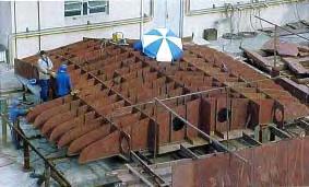
3 Chapter 7 Structural Arrangement 1.Cargo Holds Cargo holds are In general large, empty, if possible rectangular spaces where there are as little as possible stiffeners exposed to the cargo (frames, longitudinals, etc.). Only in single hull bulk carriers, old ships like single hull tankers and dry cargo ships, the cargo can be in direct contact with the ship's shell plating. Nevertheless, the hold is so important that the entire ship's construction is aimed to enable the moving of the hold and its contents (the cargo) through the water from port to port. The amount of cargo carried is the decisive factor for the earning capacity of the ship. The bulkheads of the holds are as flat as possible to make them as "user-friendly" as possible. Bulk Carriers In bulk carriers the surroundings of the tanktop in the holds, not under the hatch opening, are made sloping onward, so that the cargo slides down towards the area where the grab can take it. Also, these ships have an increased tanktop plate thickness to compensate for the wear damage caused by grabs. Hold seen in aft direction (heavy lift/multi purpose ship) Cargo hold of a capesize bulker, self-trimming, corrugated bulkhead, double hull, with a bulldozer to move the cargo under the grab.


4 1.1 Multipurpose Ships In multipurpose ships, the ship owners prefer just one very large hold. The crew can then decide on the basis of the type of cargo how to subdivide the hold. The hold is divided by movable bulkheads positioned either horizontally or vertically. The bulkheads can be attached to the sides of the hold in a very simple manner. Legal safety requirements (intact damage stability) normally require that one or more of these movable bulkheads are always in place. The actual number of division bulkheads depends on the length of the ship. Both the side longitudinal bulkheads (the boundary between hold and wing tanks) and the tanktops have manholes to enable access for inspection of the tanks. The longitudinal bulkheads have lashing points for cargo securing. Heavy cargo is often sea-fastened temporarily by means of beams and / or brackets welded to strong points in the ship's side and tanktop. This can, of course, only be done when the tanks are safe for hot work. The humidity in the bolds can be controlled by ventilation, recirculation and / or the use of dryers. Most multipurpose ship cargo holds are box-shaped. This means that the hold is rectangular and the spaces have straight walls. This is important when containers have to be carried as cargo. If the hatches and the holds have a facility to lash containers, the holds are then said to be "container fitted". Cargo hold of a heavy-lift ship Box-shaped cargo hold designed to load wood
 Floor (plate) 8.")

5 1. Bridge 2. Deckhouse 3. Engine-room bulkhead 4. Tanktop 5. Ballast tank shaped to make the hold box-shaped 6. Longitudinal bulkhead 7. (full) Floor (plate) 8. Side girder 9. Webframe 10.Toprail 11.Coaming 12.Gangway / Main deck 1. Forecastle deck 2. Breakwater on the focsle deck 3. Bulkhead 4. Tanktop 5. Holes for fitting containers 6. Manholes, entrances of double bottom 7. Longitudinal bulkhead between hold and wing tank
 are separated from each other by guide rails. During loading and discharging the containers are guided by the rails in the vertical direction.")
6 1.2 Container Feeder Ships The holds on cellular container ships are divided into multiple cells, each capable of storing a stack of 20' or 40' containers in a fore and aft direction. The spaces (cells) are separated from each other by guide rails. During loading and discharging the containers are guided by the rails in the vertical direction. In addition, the rails also keep the containers in place. Because of the small depth to keep the tonnage figure low, container feeders; have more containers on top of the hatch covers than inside the holds. 1.3 Tankers When ships are designed to carry liquid cargoes in bulk, they are called tankers. The total cargo space is then divided by watertight bulkheads in a large number of separate tanks. Each tank (in oil tankers) Is provided with: entrance hatch, escape hatch tank cleaning hatches ladder to descend in the tank, ullage and/or sounding pipe, ventilation / de-aeration pipe (closed system), filling and discharge lines, (deep-well) pump, depending on the kind of cargo, dipping holes. 1. Corrugated bulkhead (transverse) 2. Stringer 3. Main deck 4. Centre line corrugated bulkhead 5. Section of the web frame
 and overfill alarm (98% full).")
7 Every tank has possibilities for: Temperature measurement. ullage and / or sounding measurement, often radar level control, heating possibilities to control the cargo temperature, independent high level alarm (95% full) and overfill alarm (98% full). tank cleaning with fixed or hand operated washing machines. Normally the internal surfaces of cargo tanks are coated with a paint which is resistant to the cargo the ship has been designed for. Or the tanks are constructed of stainless steel. Furthermore, and depending on the size of the ship, there are additional holes in deck for transport of materials, tools, or in case of an accident, for people. The tanks have as little stiffening inside as possible to prevent the accumulation of dirt and sediment, and to minimize the area that is to be expensively coated. Crude tankers only have deckhead and the bottom coated. Inert gas is protecting the steel generally. No oxygen - no rust. The stiffening of the bulkheads is, as far as possible, in the surrounding ballast tanks. Division bulkheads between cargo tanks; therefore, are often corrugated, to minimize stiffening; however, stringers and some brackets are stilt needed. Holds can be inspected by entering via the entrance hatch and a simple ladder. The double bottom is slightly sloping towards the centre plate, to facilitate the flow of liquids to the suction of the pump. Ullage is in tanks the distance between the cargo-liquid and the top edge of the entrance hatch, (or another decisive level) on which the tank content tables are based, contrary to sounding tables. In dry cargo ships it is simply the space between the cargo (like grain), and a measuring point on deck. View of a tank on a chemical tanker with corrugated bulkhead
 4. Bracket 5. Webframe 6. Bulkhead stringer 7. Cross-tie 8.")
 14. Upper deck 15. Steering gear room / Flat 16. Aft peak bulkhead 17.")
8 Double Hull Tanker 1. Outer side shell (below deck) 2. Inner side shell (below deck) 3. Longitudinal bulkhead (below deck) 4. Bracket 5. Webframe 6. Bulkhead stringer 7. Cross-tie 8. Forepeak bulkhead 9. Double bottom 10. Afterpeak 11. Machinery space 12. Cargo tanks 13. Forepeak tank (water ballast) 14. Upper deck 15. Steering gear room / Flat 16. Aft peak bulkhead 17. Engine room bulkhead 18. Chain locker 19. Fuel bunker
 4. Bracket 5. Webframe 6. Bulkhead stringer 7. Cross-tie 8.")
 14. Upper deck 15. Steering gear room / Flat 16. Aft peak bulkhead 17.")
9 Double Hull Tanker 1. Outer side shell (below deck) 2. Inner side shell (below deck) 3. Longitudinal bulkhead (below deck) 4. Bracket 5. Webframe 6. Bulkhead stringer 7. Cross-tie 8. Forepeak bulkhead 9. Double bottom 10. Afterpeak 11. Machinery space 12. Cargo tanks 13. Forepeak tank (water ballast) 14. Upper deck 15. Steering gear room / Flat 16. Aft peak bulkhead 17. Engine room bulkhead 18. Chain locker 19. Fuel bunker


10 2. Stern Most cargo ships have the accommodation and the engine room as far aft as practicable. The accommodation is above the engine room, and by installing it all the way aft, the shafting is as short as possible. The parallel mid-body is available for cargo in this configuration. The aft part, V-shaped, still allows the various engine parts to be fitted. The working places, storage facilities and most fuel tanks are also found aft. The aft peak is the part of the ship that is enclosed by the aft peak bulkhead, the stern, shell, transom and the aft deck. The aft peak is the part of the ship, usually a ballast tank, where the stern tube is located, with the tail shaft, driven by the main engine, running through, and providing cooling for the stem tube. The stem tube is supported by high floors, to above shaft level. These high floors, at every frame, also have to sustain any propeller induced vibration. The stern section is the section above the aft peak, where the steering gear is located. At the steering flat the rudder carrier is located, taking the weight of rudder and rudderstock or kingpost. The kingpost runs through the rudder trunk (frame 0) through the upper part of the aft peak. The transom borders the aft side of the stern section. This is a plate running (nearly) the full width of the ship, on which often the name of the ship and the homeport are welded. Assembly drawing * numbers are explained in next slide
11 Transverse cross section at frame 10 Transverse cross section at frame 3 1. Funnel 2. Bridge 3. Bridge wing 4. Accommodation 5. Poop deck 6. Main deck 7. Rudder horn 8. Floor plate, frame no 3 9. Floor plate, frame no Stiffeners 11.Centre keelson 12.Stem frame 13.Bottom plate * The numbers correspond to this & previous slide


12 Longitudinal cross-section of the engine foundation Transverse see-through of the aft ship Assembly drawing of the double bottom of the engine room 1. Tanktop 2. Top plate for engine foundation 3. Brackets under engine foundation 4. Floors 5. Longitudinal girders of the engine foundation


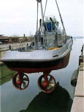
13 1. Center keel 2. Side girder (watertight) 3. Floors 4. Hole in the deck for the azipod 5. Skeg 6. Floor in skeg 7. Stiffening floor brackets 8. Longitudinal floor brackets 9. Stringer brackets 10.Azipod connecting flange Bottom view of the aft of a passenger liner The Skeg. This is a narrow vertical part added to the hull in the stern. It is necessary for the course stability of twin propeller ships. The skeg improves the course stability of the ship as it enlarges the lateral area. For dry- docking the skeg is important as it transfers the load of the aft part of the ship to the keel blocks. Top view of the aft of a passenger liner Attaching the azipod to the ship


14 The ship (a container feeder), seen from aft with a glimpse of the engine room. Here you can see ballast lines coming from the ballast tanks into the engine room. The frames in the engine room double bottom run in the transverse direction and those in the wing tanks in longitudinal direction. 1. Web frame 9. Bottom wing tank 2. Top plate engine foundation 10. Delivery suction line of wing tank 3. Tanktop 11. Side girder 4. Coaming stanchion 12. Centre keel plate 5. Upper deck 13. Full floor (plate) 6. Web frame 7. Longitudinal framing 8. Water or oil tank On the pictures above you see views from aft of two Roll-on Roll-off vessels. The open access spaces can be closed by ramps (not yet in place). When the ramps are opened, they can be used to load or discharge moving cargo 1. Freeboard deck 2. Main deck 3. A-frame, space for the propeller clearance 4. End of shafting 5. Skeg
 5. Watertight bulkhead 6. Transverse frame 7.")

15 1. Fender channel 2. Afterpeak 3. Stern brackets 4. Steering gear room (thruster room) 5. Watertight bulkhead 6. Transverse frame 7. De-aerating pipes 8. Deck girder 9. Deck longitudinal 10.Bulwark bracket 11.Towing bitt 12.Exhaust pipes 13.Wheelhouse top 14.Thruster location 15.Keel 16.Skeg (continue on next slide)
16
17 3. Engine Room The engine room is a compartment that spans in most cases the full width of ships. In tankers and bulk carriers, however, often there are bunker-tanks in the sides, still leaving sufficient space for the engine room parts. At the aft and forward ends of the engine room are watertight bulkheads: the engine room forward bulkhead and if the engine room is at the aft end of the ship, the aft-peak bulkhead. Above part of the engine room runs the engine room casing in vertical direction, towards the Funnel. Through the casing run the exhaust gas lines of the various diesel engines and the boiler(s). Part of the casing is closed by an access-hatch, allowing transport of engine parts, when opened or completely removed. Above the main and auxiliary engines travelling cranes are installed. From simple manual hoists to electric-driven hoists, capable of lifting piston heads, and pistons. The large open engine room space is stiffened with deep frames, flats and pillars in connection with the water pressure from outside, the weight of engines, and against vibration induced by them. Foundations supporting the main and auxiliary engines have to transfer the weight of the relevant machine, the induced vibrations and resulting stresses into the ship's structure. The foundations have to keep the engines in place when the ship is rolling and / or pitching and have to be stiff, to maintain proper alignment of engine and propeller shafting. All machinery is properly bolted down and provided with sideways supports to secure their position in the heaviest ship's motions. The double bottom below the engine room is often at a different level than the height of the double bottom below the cargo spaces, in order to locate the main engine at such a height, that the propeller shaft when running parallel with baseline, is at the right height for the propeller. The propeller blades have to be at a sufficient distance above the baseline to prevent damage.


 12.")
18 Construction drawings of the engine room of a container feeder 1. Aft peak bulkhead 2. Cable guide 3. Hoist beam 4. Flat 5. Main deck 6. Top plate for the engine Foundation 7. Longitudinal girders for the engine foundation 8. Longitudinal deck girder with faceplate 9. Deck girder 10. Transverse deck girder 11. Watertight bulkhead (wing tank) 12. Watertight centre line bulkhead ( wing tank) 13. Frame 23 (web frame) 14. Side girder 15. Floor 16. Web frame

19 1. Floors 2. Tanktop 3. Crown plate of the engine foundation 4. Longitudinal girder 5. Brackets with flange 6. Pillar 7. Bulkhead stiffeners 8. Stringer 9. Side longitudinals 10.Web flames 11.Side girder
20 4. Double Bottom and Wing Tanks The double bottom and the wing tanks are highlighted in the same paragraph as they have the same function. The wing tanks are located at the sides of the ship on top of the double bottom. Usually the two wing tanks are separated in the sense that no fluid can flow between them. Sometimes; however, the two tanks are joined in a U-shaped or L-shaped fashion. The functions of the double bottom and the wing tanks are: -to increase the transverse and longitudinal strength of the ship. -additional safety when the bottom or side is damaged or in case of a collision (damage stability). -to store seawater (ballast water) so that the propeller is below the water surface, and the forward draught is sufficient to prevent pounding, even when the ship has no cargo on board. This is also advantageous for the stability of the vessel. -to store fuel -to provide the list and trim control -to compensate for uneven loading. Ro-Ro ships are often fitted with a heeling system. This is a system which automatically pumps ballast water from one wing tank to the opposite wing tank very quickly, to compensate for a list due to cargo coming or put on board. Pumping of ballast water from one wing tank to the other will automatically minimize the list. Tanks are by definition watertight compartments. In the double bottom, the separation of the two sides is accomplished by the centre keel or the side girders in the fore and aft direction and with a watertight floor in the transverse direction. An oil tank and a drinking water tank must be separated by an empty space, a so-called cofferdam. The wing tanks are separated by watertight web frames. The shell stiffeners in the double bottom and the wing tanks are usually run in the longitudinal direction. When a ship has a length of approximately 60 meters or less, for instance a tugboat or fishing vessel, the frames run in the transverse direction. Sometimes a combination of the two systems is used, when the double bottom and the main deck are longitudinally framed and the side ones are transversally framed. The double bottom is covered by the tanktop, and thereby separated from the hold. Several piping systems run through the double bottom, such as piping for fuel., bilge or ballast water systems. Containerships need reinforcements in the double bottom in way of the corners of the containers.
 Vents and openings are installed for the filling and emptying of the tanks.")

21 Meer plates In abs double bottom can be divided into: -water- or oil-tight Floors (Non-tight plate floors) -floors, which can be reduced in weight by manholes (also for access) -floors made of profiles and brackets (open floors) Vents and openings are installed for the filling and emptying of the tanks. Every double bottom tank must be fitted with a sounding pipe, normally aft (with a small doubling under) and a vent pipe forward and aft in each tank. Tank contents are often measured by special measuring devices, with a display in the cargo control room. This can be a float, connected to a counter, sending a signal to the computer in the control room, a bubble-pipe system working on air pressure or even a thank-radar. The double bottom is accessible by bolted manhole covers in the tanktop; every tank must have a possibility for entrance. Fuel tanks often have a system of heating of the fuel (depending on the type of oil). Most ships burn heavy fuel, and the viscosity depends on the temperature. The fuel tanks; therefore, are usually provided with heating coils, through which hot water, steam or thermal oil is circulating. 1. Bilge plate 2. Side girder 3. Full floor (plate floor) 4. Tanktop longitudinal 5. Bottom frame
 16.")
22 1. Centre keel (watertight) 2. Side girder 3. Bottom longitudinal 4. Watertight or oil tight floor (plate floor) 5. Full floor (plate floor) 6. Centre keel bracket (docking bracket) 7. Ballast line 8. Bilge line 9. End of ballast line, with suction 10.Side shell longitudinal 11.Watertight or oil tight bulkheads 12.Web frame 13.Hatch coaming 14.Coaming bracket 15.Maindeck (gangway) 16.Ballast or fuel tank 17.Top plate of engine foundation 18.Poop deck 19.Ventilation trunk of cargo hold 20.Deckhouse front


23 Location on the ship Double Bottom Transverse Cross-Section 1. Full floor (plate floor) 2. Side girder 3. Bilge bracket 4. Bilge keel 5. Recess container pot 6. Airholes 7. Drain holes 8. Tanktop 9. Tanktop longitudinals 10. Bottom longitudinal 11. Port side 12. Starboard side 13. Longitudinal framing system 14. Transverse framing system. 15. Floor on frame Floor on frame Floor on frame Longitudinal slots 19. Bottom shell 20. Heating coils 21. Synthetic pipe fee ballast tank (numbers apply for this and next slide)


24 Double Bottom Longitudinal Cross-Section (numbers are explained on previous slide)


25 Location on the ship Double Side Transverse Cross-Section 1. Hatch coaming plate 2. Toprail 3. Gangway 4. Deck longitudinal 5. Side shell longitudinal 6. Shell plating 7. Longitudinal bulkhead, tank side 8. Scallop


26 1. Main Deck 2. Deck longitudinal supporting the tip of the coaming bracket 3. Stringer 4. Web frame 5. Side shell longitudinal 6. Full floor (plate floor)


27 This isometric shows an open wing tank and a double bottom of a Ro-Ro passenger ferry. The cross-over line is visible as an open line between the portside tank and the starboard tank. A cross-over in this case is designed to be used in the event of a collision. Water entering one space will flow to the tank on the other side. This will moderate the list. 1. Longitudinal bulkhead 2. Bilge well 3. Heating coils 4. Bilge line 5. Cross-over line The system can result in reduced damage stability requirements. The majority of ferries and passenger liners have such a crossover system. The drawings show: - Bilge wells; fluid present in the compartment will flow to the bilge well and can then be removed by the bilge pumping arrangement. - Heating coils; these are in the heavy oil tank. If the oil is too viscous to be pumped, it will be heated up to a 'safe viscous' temperature.


28 1. Draught mark 2. Plimsoll mark 3. Deckline 4. Bulwark 5. Container strut 6. Bilge shake, approximately 10 mm thick 7. Backing bar 8. Bilge keel, approximately 220 x IS ram (for this particular ship) The bilge keel is welded onto a flat bar. When damaged, the bilge keel should break off, with the strip remaining attached to the shell. Without backing strip, a crack in the bilge keel could continue into the bilge shake, and that is dangerous! Cross section of the midship Bilge Keel Side View

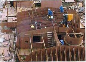
29 5. Bow The bow is the part of the ship between the stem and the collision or forepeak bulkhead, and the adjacent part aft of the forepeak, to the parallel mid body. The space forward of the collision bulkhead and below the maindeck, is the forepeak. The forepeak tank is the lowest space in the bow and is often divided in a lower and an upper forepeak tank. The forepeak tank is usually used as a ballast tank. If the ship is not loaded, this is often filled with water to increase the draught and to reduce the trim by the stern. Usually there is a wash-bulkhead at the centre line in the peak tanks. This prevents sloshing (the fast movement of water from port to starboard) when a tank is partly filled. It also improves the rolling-behavior of the ship. Directly behind the forepeak there can be another tank (deeptank) that extends from starboard to port and front the bottom to the deck; used for ballast or fuel. In the top of the forepeak, right below the anchor windlass there are chain lockers for the storage of the anchor chains. Above the weather deck in the bow there is often a forecastle, a superstructure from bow to at least above the collision bulkhead. Sometimes extended further aft, to even aft of number one hatch. The forecastle is protected against overcoming sea by a bulwark. On the forecastle is the windlass and other mooring equipment. The foremast is usually located at the after part of the forecastle deck. The forecastle can be divided into: - stores and workshops for ship's maintenance: tools for work on the deck (bosun's store, carpenter's store) storage for paint (with fated fire-fighting equipment) storage for ropes. - Storage for cargo handling equipment like: twistlocks, (container lashing equipment) slings, shackles, airbags. These items are usually stored in racks made for this purpose. if necessary, these racks con be lifted up by the ship's crane or the crane of the hatch cradle. Container-lashing gear is often stored in boxes along the hatch coaming. Fore part is being attached to the ship


30 1. Bow 2. Forecastle deck 3. Break water 4. Bulbous bow 5. Main deck 6. Stringer 7. Bow thruster room 8. Hatch coaming with brackets 9. De-aerating pipes 10.Top rail 11.Vent of the wing tank 12.Access / lightening opening 13.Transition of transverse to longitudinal framing system 14.Tank top 15.Web frame


31 The bow is subject to extra large forces, acceleration and stresses caused by: a. the pitching of the ship (pitching stresses). b. the forepeak moving in and out of the water (panting stresses). c. maintaining speed in heavy weather. d. Ice. Bulbuous Bow Items stored in the forepeak spores need to be properly seafastened, in connection with the acceleration forces. To compensate for the forces mentioned, the forward part of a ship needs additional reinforcements that sometimes extend to all midships. A bulbous bow can be added to reduce the wave-resistance. The bow wave and fore-shoulderwave cause a resistance that has a negative influence on the speed of the ship. The added bulb creates a wave which interferes with the bow and shoulder waves ideally eliminating them, thereby improving the wave resistance of the ship, however, only for the draught the bulb has been designed for. The bulbous bow is in fact a piece of protruding bow that produce its own wave that cancels out the normal bow wave, this way improving the wave pattern around the ship. All depending on the design of the bulb, from a long knife-type-form, to a ball-form. The ideal situation is one where the ship cuts through the waves, generating no waves itself. Every wave that is created by the ship is energy wasted; compare a tugboat with a fine yacht. The bulb is most effective at a certain draught, for loaded or ballast condition. It could well be that in the case of the adverse situation a bulb produces more resistance.
 11. Hawse pipe 12. Anchor pocket 13. Chain locker 14. Watertight bulkhead (collision bulkhead) 15.")
 23. Floors 24.")
32 1. Bulbuous bow 2. Breasthook 3. Floor 4. Floor stiffener 5. Access / lightening opening 6. Stringer or flat 7. Centre keel in bulb 8. Stembar 9. Transition of flat to shell stringer 10. Shell frame (HP) 11. Hawse pipe 12. Anchor pocket 13. Chain locker 14. Watertight bulkhead (collision bulkhead) 15. Ladder to the forecastle deck 16. Weather deck (main) 17. Emergency fire pump / bilge pump 18. Bilge line in bow-thruster room 19. Forepeak (water ballast) 20. Bow-thruster tunnel 21. Floor slab in bow-thruster room 22. Deeptank (water ballast) 23. Floors 24. Wash bulkhead at the centre line of the ship Assembly drawing Location on the ship


33 Fitting of the shell plating Forepeak ready to be installed Longitudinal cross-section of the forepeak Transverse cross-section at frame 127 Transverse cross-section at frame 121 Horizontal cross-section at 3.40 m above the baseline


34 1. Bulbuous bow with stringers and floors 2. Bow-thruster room 3. Focsle deck 4. Coaming foremost hold 5. Steps in foremost hold for containers 6. Collision bulkhead 7. Ballast tank 8. Spaces in focsle Container ship


35 Port side shown A detailed drawing of the part of the ship shown left is shown below left giving clear picture of the various framing systems. Note that the web frames are never isolated, but are always part of a ring frame. For every three frames, there is a web frame. The stiffening under the main deck runs in the longitudinal direction. Directly underneath this is the icebelt; in this section, there is an extra frame for every frame. The ice strake can run all the way from forward to the place where the ship is at its widest. 1. The aft direction 2. Main deck 3. Deck beams 4. Deck longitudinal 5. Longitudinal bulkhead with longitudinal framing 6. Longitudinals 7. Transverse framing for ice strengthening 8. Transverse frame Aft
36 6. Accommodation 6.1 Introduction In the past, the accommodation of the crew was not the most important aspect in the design phase. A reason for this was the large number of men in the crew compared to the present day. Thirty years ago (circa 1970) a crew of forty manned a vessel that today may do with a crew of twelve. Due to the added workload of today's crew, there is a growing pressure to improve facilities for the personnel. When the size of the ship permits, cabins are for one person only, have separated day and bed room, are well equipped, and have their own toilet and shower. As a result of smaller crews and shorter lay days, the importance of recreational and leisure facilities has grown (a gym, satellite telephone connection from all crew cabins, central antenna system, etc.). The height of the accommodation is important for the view from the bridge. Large ships, with the accommodation aft, and, when in ballast a considerable trim, and thus a long dead sector, need a higher accommodation than ships with the deckhouse forward. 6.2 Safety In particular safety equipment demands focus on the prevention of fire. These demands are stated in the SOLAS resolution, chapter II-2 "Construction - Fire protection, fire detection and fire extinction". The chapter consists of the following parts: Part A: General Part B: Fire safety measures for passenger ships Part C: Fire safety measures for cargo ships Part D: Fire safety measures for tankers. 6.3 Environment a. Vibration Vibrations are usually accompanied by sound or noise as vibrations and noise often have the same source. On a ship those sources mostly are the propeller, the various diesel engines and even the waves at sea. Insulation techniques and the prevention of local resonance are used to keep the vibrations in the accommodation and at other locations within


37 acceptable levels. Installing the diesel engines on cushion-mounts reduces vibrations considerably. Vibration has a negative effect on many things. Writing can be difficult, sophisticated machinery gets damaged. Resonance can result in fractures in the structure. (ISO criteria: vibrations of 4-5 millimeter/sec are tolerated. Values larger than 10 mm/sec are unacceptable.) b. Noise Nuisance Too much noise is disturbing and irritating and therefore has a negative impact on the working and living conditions on board the ship. Noise will affect: -the communication in the engine room and the communication on the bridge (the listening aspect of keeping watch is hampered). -conversations in the common spaces. -the peace in cabins where a low noise level is required and disturbance by music etc. from other spaces is not appreciated. -condition of persons -quality of rest (Disturbing) noises come from: -propulsion installation, propeller and auxiliaries -AC and ventilation systems and cabin refrigerators. -crew, music, TV, toilets, etc. Noise is measured and expressed in decibels. The following maximum values apply for ships: -day rooms, mess room etc.: 65 db -cabins, sick bay.: 60 db -galley, control rooms: 75 db Cross-section of a flexible support An engine placed on cushion mounts


38 e. Air Conditioning Air conditioning in the accommodation and control rooms is normal today. The air conditioning and climate control requirements of a space will depend on the outside temperature, and outside relative humidity. Air conditioning normally consists of a ventilation cabinet where outside air is sucked in, cooled to remove the moisture, and afterwards heated to the desired temperature. The total air quantity or number of air changes is maximized by the noise criteria. Needless to say that a proper insulation of the accommodation is a prerequisite for the realization of a good inside climate. d. Lighting and Daylight High demands are set for lighting in working and living spaces. Lighting armatures should be able to resist the vibrations on a ship and they should be easily accessible for maintenance. Windows (portholes) in cabins and other spaces should have such dimensions and placing, that one is able to look outside both sitting down and standing up. There are also certain requirements for portholes, like the design pressure and the position on board (e.g. not below the freeboard deck). 6.4 Methods of Insulation Insulation material has to be installed against temperature differences between inside and outside, against heat in case of fire and against noise. All accommodation decks and bulkheads which are in contact with outside, or with hot locations in the ship such as the engine room need to be insulated against heat and cold Weathertight door 2. Insulation on welding studs, covered by wired mesh Galley Port hole 3. Moisture-proof aluminum foil

 2. HP profile 3. Glass wool 4.")
39 a. Rock or Glass wool patches Fire & thermal insulation - Walls Batts of rock wool or glass wool are attached to welded pins that have already been placed on the steel plating. Thickness is depending on the difference in temperature inside and outside. The drawing shows an example of fire protection and thermal insulation. The panels of the accommodation are free of contact with the insulation to prevent the transfer of vibrations. The panels are attached to, for instance, U-profiles which, in turn, are attached to the insulating floor. 1. Steel plate (outside accommodation or inside boundary) 2. HP profile 3. Glass wool 4. Welding stud 5. U-profile 6. Accommodation panel (a galvanized steel plate of 1 mm thickness) - Flooring To minimize disturbing sounds and to reduce the chances of fire, the floors (especially if they are directly above the engine room) are built as sprung floors. These floors can consist of multiple layers of steel wool with a large density (e.g. baffles) placed on the steel deck, covered by a hard ground slab. b. Sprayed Poly-Urethane Insulation (or other foam) This form of insulation is sprayed as a liquid on the bulkhead, expanding into foam instantly. Spray insulation can be used for thermal insulation, sound absorption and fire resistance (melting temperature can be up to 750 C). 6.5 Communication Each cabin has to be equipped with a telephone and a terminal for a central antenna for radio and TV. For operational and safety reasons it is necessary that each member of the crew can be summoned or warned at any time and any place. Applying insulation 6.6 Maintenance Cleaning and maintenance of the accommodation is a necessity for both the hygiene and appearance. In general, the arrangement of the accommodation should be aimed at easy and efficient cleaning and maintenance. Things that have to be taken into amount are: -preventing of dirt transfer from work to living space -proper choice of materials (clean and easy to maintain)
40 In the design phase it is important to: -include enclosed compartments where dirty overalls can be taken off and hands can be washed. -a cleaning-gear locker en every desk in the accommodation. 6.7 Overview of the different spaces Bridge Always on the highest deck. This is where all the means of communication and navigation are situated. Connections need to be provided with engine room, steering gear room, all the cabins, etc. Some ships even have the engine control panel in the wheelhouse. From this point an item such as the ballast system, which is located in the engine room can be accessed. Duty deck On large ships, the lowest deck in the accommodation, often one deck above the main deck, is a working deck where you can find the cargo office, the captain's office, the meeting room the galley and the mess rooms. Apart from the bridge every space above this deck is private. On the duty deck combinations of use of spaces depends very mush on the size of the ship. Captain s Office For the captain is a (small), sepa-rate office. Cargo Office This is the room where the captain or chief mate deals with agent, cargo-receivers, customs, ship chandler, suppliers, etc. Meeting room A place whore deity work meetings are held. Cargo Control room On board tankers and bulk carriers, the loading and discharging, ballasting and de-ballasting is controlled from the cargo control room. Smaller ships can have a control panel on the bridge.
41 Galley. The food is prepared here. It is situated near the mess-room to keep the walking distance as small as possible. Mess-room Dining room for officers and crew. Duty-mess A small room with table, chairs and a cabinet where crew can eat in dirty clothes, in case there is too much work on deck or in the engine room. Next higher deck: Lounge This is the focal point of social activities outside working hours. Laundry A space located centrally, with at least a washing machine and a dryer. Hospital The arrangement of this space is subject to legal demands. Furthermore, it has to be easy of access for a stretcher. Cabins These are being standardized more and more. For example: the captain, chief engineer, chief officer and lower officers all have a cabin of similar size. Next to these, there are maybe one or two other types of cabins. Nowadays, cabins can be finished completely at the working place (prefab). After placement on the ship only terminals for electricity, water, ventilation, heating, etc. have to be installed and connected. Owner's Cabin Usually at the same deck as the captain's cabin, chief engineer s cabin, an Owner's Cabin is located, of a quality, similar to that of the captain's cabin. This is a passenger's cabin, for office staff, a pilot. superintendent or other person not belonging to the crew. For occasional workers, there is usually a cabin with 4 or 6 bunks, lower in the ship, eventually combined with the cabin for the Suez-mooring gang, needed when the ship has to do a Suez Canal transit. Stores Store rooms are found where the items to be stored belong to: -provisions and cold stores near the galley -bonded store, also near the galley -luggage lockers on all cabin decks

42 -engine, spare parts and tools near or in the engine room -paint locker, forward or aft, isolated from the accommodation, with entrance from outside only, -garbage locker near incinerator, and galley, only accessible from outside. The main deck, below the accommodation spaces, is again depending on a ship size, used as the work deck, or for stores, engine room stores, etc. Divisions depend on use. Often a CO2 room finds its place here. Lockers in the accommodation
43 Chapter 8 Closing Appliances 1. Introduction Dry cargo skips have cargo holds which as a rule are closed against sea and weather. For centuries this was done using a system of wooden planks, covered by tarpaulins, secured by bars and wooden wedges. This often failed. The first steel hatches were MacGregor's Single Pull system, developed during World War II, and first installed on the Victory ships. This was a major step forward, as they were perfectly weather tight, by using rubber seals and compression bars, carefully adjusted to match each other. They are still in use on many ships. Generally, holds have an opening at upper-deck level, surrounded by a wall, the coaming, to prevent water running into the hold, and to stiffen the edge of the deck. In some containerships the closing appliances are omitted. Their absence has been compensated by bilge pumps with a huge capacity. Cargo hold covers, or hatch covers need to fulfill the following requirements: -Sufficiently strong, to withstand sea water -Weathertight -Easy to open and close -Maintenance friendly -Strong attachments Special tasks can require extra strength: -Deck cargo like containers or timber, and lashing possibilities for same. The sealing system of the various hatch cover systems are all based on the controlled compression of a rubber seal against a steel flat bar, either horizontal or upright. These rubber seals and compression bars need careful maintenance as they are decisive for the weather tightness of the hatches. Water ingress often means cargo damage.
44 Hatch cover types and systems are chosen based on parameters such as: -the type of cargo the ship is designed for, -the availability of lifting appliances,on board or ashore, -the service area where the ship should sail, Containerships usually have huge covers or pontoons, which are lifted off by the shore container crane, and stacked on top of each other, or simply laid ashore. Bulk carriers usually have side rolling hatches, one set per hatch, general cargo ships or multipurpose ships have pontoon hatch covers or folding hatch covers, Ro-Ro ships have stern ramp doors, bow doors or side ramp doors, Tankers have small covers, only for access for people and tools. 2. Weather Deck Hatch covers 2.1 MacGregor Single Pull During the past 50 years, the most common steel hatch cover in use was the MacGregor Single Pull steel hatch cover. Each rectangular cargo hatch is covered by approximately six transverse sections. After being lifted from the compression bars, they can be rolled to a stowage area at the end of each hatch. There one by one, the covers turn vertical and are stowed against each other on the guides. Closing the covers is simply done by pulling the hatch covers towards the other end, and lowering same when in position. The pulling wire comes usually from the ship's cargo gear. This system has been (and still is) in use for ships up to 50,000 tons deadweight. 2.2 Pontoon hatch covers General Today, general cargo ships up to 10,000 tons deadweight, have one large cargo hold, with division bulkheads which can be positioned where needed. The common hatch cover for this kind of ships (multipurpose ships) is the pontoon hatch cover. Approximately 80-90% of these vessels use this type of covers. Pontoons come in many configurations. Often they are closed on the underside, sometimes even watertight, so that they can be stored during loading or discharging in the water, beside the ship. The hatches (maximum weight 25 tons) are opened and closed by lifting and lowering of the pontoons, by a crane on the ship or on the quay. The crane on the ship often is a hatch cradle, a travelling crane, which can also move the pontoon hatch covers over the ship in the longitudinal direction, and stack the pontoons on the coaming, where wanted. The hatch cradle cannot be used for cargo.


45 1. Coaming 2. Wheels and connection chains 3. Hatch panel 4. Horse 5. Pull-wire 1. Pontoon Hatch cover 2. Hatch cradle 3. Beam 4. Hatch coaming 5. Toprail 6. Hold 7. Tanktop with open manhole 8. Wedges Reasons for choosing pontoon hatch covers in combination with a hatch cradle are: -easy maintenance. The system has no wheels or other movable parts. When in position they only need to be secured to the coaming and to each other, -flexibility in cargo hold configuration: Movable tweendecks and grain bulkheads can be positioned with the hatch cradle Type of hatches Pontoon hatch covers can be divided into closing hatch covers, intermediate hatch cover and end covens. If a hold has to be closed, then the intermediate hatches must be closed before the closing hatches, and the other way around when the hold is opened. Sometimes there is a short hatch in between with a width of one meter or less; this is called a (hatch) beam. These are not always present or necessary. The weight of a hatch can be somewhere between 10 and 25 tons. A beam acts as a smell intermediate hatch and has the advantage that one can easily open just a part of the hatch covering.. This is an advantage when it is raining. Sometimes the beam is left in place during cargo handling to absorb the deformation forces between port and starboard hatch coaming.


46 2.2.3 Positioning of a pontoon hatch The positioning of pontoon hatch covers is achieved by tapered pins (centre-punches) at the side of the cover, fitting into holes in the coaming toprail. On one side, the hole is a tight fit, and on the other side it allows approximately 60 mm side-ways movement. As a result the pontoon hatch cover has the possibility to move several millimeters over the sliding blocks in the transverse direction. This prevents the hatch from getting stuck if the width of the hold changes by a few millimeters, due to forces during loading. Note: The sliding of the pontoon hatch-cover is an apparent movement, not a real one. In reality the toprail is moving under the hatch. Multi-purpose ship with pontoon hatch covers Beam between two closing hatches 1. End hatch 2. Closing hatch 3. Beam 4. Intermediate hatch 5. Wedges 2.3 Hydraulic Folding Hatch covers Folding hatches are opened and closed by means of hydraulic cylinders. The location of the cylinder depends on its type. a. Cylinders attached to the outside of the hatch use the head ledge as a fixed point. This type is only possible if it leaves enough walking space at the deck side (minimum of 60 cm). b. Cylinders which are supported by the beam. The pistons that push the hatch up or down are located at the main hinges. Advantages: - faster opening and closing compared with pontoon hatches, - the hatches can cover the holds over the entire length of the ship (there is no hatch cradle blocking their way) -more easier hatch to control, area per especially hatch; this in means bad weather that there are fewer transverse seams and therefore less length of rubber seals (e.g. instead of 10 pontoon hatch covers, only 8 folding hatches are required).

 2. Hatch 3. Main hinges 4.")
47 Disadvantages: -the high acquisition cost -the vulnerability of the hydraulic system -vulnerable to damage by shore crane, due to height. Hydraulically operated folding hatches need safety devices, against collapsing when in open condition: -ruptured hose safety system. This prevents the hydraulic system from emptying. -if the control button is released (dead man's brake), the system will stop. -For example, if the control button is on starboard, a dead man's break should be installed on port side. Emergency brakes can also be installed. -a safety hook. This prevents the opened hatches from slamming shut. 1. Hinges between two parts of the hatch (hatch hinges) 2. Hatch 3. Main hinges 4. Cylinder 5. Wheel 6. Ramp Hydraulic System Ship with opened (hydraulic) folding hatches


48 2.4 Side-Rolling Hatch covers Large bulk carriers, ore carriers and oil-bulk-ore carriers are usually provided with side-rolling hatch covers. This type of hatch cover opens and closes in transverse direction. When in closed position, they are resting on special pads, which adjust the compression of the rubber gaskets. Before they can be rolled towards the sides of the ship, they are lifted, usually hydraulically. During lowering-down of the hatches, in the closing operation, the covers are exactly positioned by V-shaped catches, to bring the gaskets above the compression bars. The hatches are opened and closed with chains or cogwheels. These are driven by (hydraulic) pumps located near the hatches. The individual hatch covers have to be secured to each other and to the coamings by means of bolts and/or quick acting cleats. On large vessels especially, the hatch coamings have to withstand distortions of the ship as a result of the varying types of cargo, and the state of the sea. Advantages: Disadvantages: -minimal jointing length - large -easy opening and reclosing - heavy -low air draught of the hatch covers -maintenance friendly Bulk carrier with side rolling hatches, two covers on each hold Ore carrier with single side rolling hatches

49 2.5 Piggy Back Hatch covers Another way of opening and closing of hatch covers is the fore and aft rolling pontoon system, called piggy back. Two covers close together the deck opening. One cover can be lifted from the coaming by hydraulic plungers till a height, sufficient to allow the other cover to be rolled underneath the lifted cover, after which the upper cover is lowered till it rests onto the lower cover. Together they can roll, by an electric drive inside the pontoon, either above the forward half of the hold or above the after half. The covers can have a height of approx. one meter and can have a weight of tons. They are in use on containerships and log carriers. Often heavily constructed for (heavy) deck cargo. 2.6 Open Cargo Holds (No hatch covers) Some ships have holds, without hatch covers. Some containerships, socalled open-hatch-ships, just do not have hatch covers. The holds need to be equipped with extra heavy bilge pumps to cope with any water that enters the hold. The containers in the holds prevent a free water surface. The largest quantity of water to be dealt with is not bad weather, but a tropical rain shower. Having no hatch covers saves the time needed for opening and closing. Some types of dredgers also have open holds. There the cargo comes on board as slurry: a mix of water and sand. The sand settles, and the surplus water flows away over the side. When the hold is full with settled sand, the remaining water is pumped out Piggy back hatch cover 1. Lower cover 2. Upper cover 3. Lifting plunger 3. Distortions of the ship During loading and discharging a ship with a long hatch opening can be somewhat distorted. This phenomenon is called harbor deformation. The distortions can be prevented by the placing of one or more beams or hatches in the transverse direction. If in spite of this, distortion still occurs, it can cause the hold walls and thereby the toprail to move several millimeters out of position. Stainless steel sliding blocks are welded onto the toprail to guide the sliding of the hatches along the toprail.

50 Furthermore, the sliding blocks (5mm thick) adjust the position of the covers in height. The sealing rubber with or without compression bar, is allowed to be pressed a maximum of 10 mm, to prevent damage to the seal. The hatches are not constructed to absorb the forces acting on a ship in waves. This is why there is a movable and fixed side. Containerships, and bulk carriers at sea, suffer from torsion in the hull, forcing the rectangular hatch openings to become a parallelogram. The rectangular hatch covers continuously slide with the rubber gaskets over the compression bars, or over the coaming. The covers wear at the resting pad areas. Therefore, special sliding pads have been developed, consisting of layers of different materials. These pads allow sliding, and carry the weight of the cover. Greasing the rubbers before closing the hatches, helps to reduce the wear. 4. Weather Tightness Hatch covers have to seal the hold weather tight. This weather tightness is achieved by: 4.1 Rubber sealing gaskets Rubber sealing gaskets, glued in a channel in the cover, and resting with a controlled compression on the coaming, on a flat surface, or on a vertical compression bar. The compression is controlled by resting pads, adjusted in height, to obtain the desired compression. The sealing gaskets have a back-up in the form of a save-all, a gutter, collecting the drops of water which managed to pass the rubber gaskets. Often this gutter is double installed. This save-all is fitted between the rubber and the coaming edge, and between hatches, in transverse direction, below the jointing rubber, leading the leakage water to the coaming. The corners of the coamings are provided with a drain. 4.2 Cleats Cleats on the outer edge of the pontoon hatch cover fix the hatch cover to the coaming. 4.3 Wedges Wedges, to adjust the transverse joints compression.

51 4.4 Checking Weather Tightness Hatch covers have to be checked for tightness regularly. It can be done as follows: -The hose test. A powerful jet of water is sprayed against the joints of the pontoon hatch cover, while simultaneously the hold is checked for leakage. -With the aid of ultrasonic detection equipment. A transmitter of sound waves is placed in the hold along with a detection microphone (receiver) on top of the hatch cover or moved along the coaming. If the detector does not 'hear' a sound at the transmitted frequency, the hatch is considered watertight. Checking the tightness of hatch covers is commonly performed by charterers and P & I clubs prior to loading. It is the normal test when the ship is new, during commissioning, at Annual. Survey, at Special Survey, or after repairs when the Classification inspects the hatches. Intermediate hatch Circumferential seam sealing 1.Rubber gasket 2.Compression strip (fore & aft direction) 3.Toprail 4.Pontoon hatch cover 5.Compression strip for the circumferential seam sealing 6.Hold 1.Closing hatch 2.Intermediate hatch 3.Compression bar 4.Rubber gasket 5.Gutter
 need a crane (on board or ashore) to open and close")
 -steel cables operated by")

52 5. Hatch Cradle Ships that are equipped with pontoon hatch covers generally have a hatch cradle to open and close the holds. Ships with a carrying capacity of more than 10,000 tons (especially container ships) need a crane (on board or ashore) to open and close this type of hatches. The lifting and lowering of the hatches by the hatch cradle is done by: -hydraulic cylinders (up to 14 tons) -steel cables operated by winches on the loading platform of the hatch cradle (up to 21 tons) Hatch Cradle Top view of the hatch cradle, the fixed bridge Top of the Hatch Crane 1.Electro-hydraulic pump 2.Control box 3.Winches with steel cables for pontoon lifting 4.Stores crane 5.Control box stores crane 6.Movable bridge 7.Columns 8.Wheel with hydraulics, two of the four wheels are equipped with brakes 9.Reel for the feeder cable


53 Hatch cradles are usually equipped with two stores cranes. These cranes are capable of: -Loading and discharging provisions and engine parts -lifting of materials in and out of the hold -carrying materials over the entire length of the ship. -This crane can rotate 360, but cannot be tapped or lowered. With the cradle one can also operate the working tray for work in the hold like: -handling grain or separation bulkheads -handling the supports for the tweendecks The height of the working tray in the hold can he controlled by the person operating it. The steel cables that control the movable bridge can be disconnected and attached to a bulkhead. These bulkheads can then be positioned anywhere in the hold by the hatch cradle. The bulkheads can then be used as tweendecks or separation bulkheads. Safety on the batch cradle: -an optical signal with a bell if moving -emergency stops on the hatch cradle: *on the loading platform *the bottom side near the gangway (P and SE) *speed brakes in the hydraulic system will immediately come into action in case of a hydraulic leak. Cargo hold of a cargo ship, divided in two parts, using the movable bulkhead. The forward part for bulk cargo, the aft for packed cargo 1.Pontoon hatch covers 2.Pontoon & bulkheads in storage 3.Entrance


54 6. Tweendeck Hatches Tweendeck hatches come in the following versions: -pontoon hatch -folding hatch Tweendeek hatches are normally not provided with gaskets. 6.1 Pontoon hatch Pontoon hatches are mostly found on multipurpose ships where their function is twofold. Pontoon hatch covers can be placed both horizontally (tweendeck) and vertically (grain or separation bulkheads). The positioning of the pontoons is done with the means available on the ship, such as a hatch cradle or a crane. If the pontoons are not in use, they are stored vertically, in a special stowage. 6.2 Folding hatch Tweendeck folding hatches are common on ships which are provided with more than one tweendeck, such as reefers. On reefers, having three tweendecks, there is usually one tweendeck where the folding hatch is fitted with thermal insulation. The folding hatches of tweendecks are normally operated mechanically. The cargo runner of the crane is used to open the hatches. Tweendecks with folding hatches on a reefer vessel A ship s crane opens a folding hatch The drawing shows how, with the help of the hatch cradle, the bulkheads can be placed in different positions
 are used to load and discharge vehicles. Generally, these doors are controlled hydraulically. A side door locally weakens the strength of a ship.")
55 7. Entrances 7.1 Side doors Side doors are found on ships with a large freeboard, like passenger liners. These vessels use this door to embark and disembark the passengers. Larger side doors (ramps) are used to load and discharge vehicles. Generally, these doors are controlled hydraulically. A side door locally weakens the strength of a ship. This has to be compensated for by locally thicker side shell plating and heavier internal structural parts. 7.2 Stern doors and ramps Ro-Ro vessels load and unload often via stern doors and quarter or slewing ramps, combining the function of bridge between jetty and ship and watertight closure of the cargo hold. Because of the weight of the lorries, these doors/ramps are heavily constructed. They are supported at the stem of the ship in the hinges, and at the jetty. The span can be considerable. Opening and closing is done by wires, via hydraulic cylinders and jigger-winches. The hoisting wires are often backed up by a heavy wire or chain, to prevent lowering too far in case of wire failure or hydraulic failure. 7.3 Bow doors Ro-Ro passenger vessels on short voyages, such as the Cross-Channel services also have bow doors. There are various types: horizontal sliding doors, vertical moving doors, and ramp-door combinations. The latter type is often protected by a bow- visor, where the whole bow hinges upwards, giving access to the ramp, which is the real watertight door. After a number of accidents, strength, securing and security of the various systems have gotten more attention, requirements became more and more stringent during the last years. Ro-Ro ships also have ramps between upper car-deck and lower car-deck. This ramp is, when closed, part of the upper car-deck, and also part of the weather tight closing of the ship. These ramps therefore are provided with rubber gaskets as hatch covers. Opened side door, equipped with hydraulic cylinders for opening and closing


56 7.4 Companion hatches Companion hatches come in many shapes and sizes. Some types are discussed below. Storage compartments often need a wide entrance because the stored parts can be quite large, such as engine pans, lashing gear etc. The companion hatches can be opened manually or with the aid of a crane, a hatch cradle or a hydraulic system. Companion hatches on oil tanks can be sealed from open air with a cover that makes the hatch impermeable to oil and gas. The cover itself is closed with clamps. Just above the cover is a screw-thread on a wheel that is used to lift the lid and subsequently turn it away from the hatch coaming. The hatch covers sometimes are provided with a smaller hatch that is used to take samples, determine the ullage and the temperature of the cargo. Type of exterior doors that can be opened with just one bar 7.5 Accommodation doors Exterior doors Exterior doors are weather tight. This means that, if the door is closed, it will only leak when submerged in water. The exterior doors are often opened and closed with a central bar or wheel, serving up 60 toggles. The difference in the exterior doors shown below is the number of closing points. This determines the quality of the tightness. Hydraulically controlled entrance hatch Interior doors These doors are inside of the weather tight doors. Fire fighting regulations can demand that there is a fire barrier in the accommodation. This can then be achieved by using metal fireproof interior doors, automatically closing in case of fire alarm. Weather tight door


57 7.6 Watertight doors These are really watertight closing appliances, used in watertight bulkheads, for instance between engine rooms. They are designed to withstand water pressure, depending on the height they are installed. Watertight doors can be controlled locally, manually and hydraulically, as well as on the bridge. The control panel on the bridge indicates if a watertight door is opened or closed. The doors are operated hydraulically. Even if the whole compartment is filled with water, the watertight doors should not leak. 8. Miscellaneous 8.1 Ventilation Louvers All the vents of the holds, the engine room and the accommodation are shielded by gratings, often louvers. These have to be provided with means for closing weather tight and air tight by a cover in case of bad weather or fire. 8.2 Manhole covers Manhole covers close the access openings that are part of every tank, except for the cargo tanks. Manholes make it possible to inspect a tank. 8.3 De-aeration devices - Tank vent / overflow Every liquid containing tank must have a means of venting in order to prevent over, and under pressure during emptying or filling. For this purpose, every water and oil tank has a venting possibility. This pipe ends on the freeboard deck at a vent terminal with a closing device, preventing seawater entering the tank. In case of submersion of the tank bleeder, a floating ball inside the tank bleeder will float upwards until it is pressed against a rubber ring. Manhole cover Different types of vent terminals Watertight door Ventilation louvers Rotating cover on a cargo oil hatch

")


 that it can never catch fire. The gas rapidly diffuses into the air and will not fall back to the ship.")
58 This mechanism seals the pipe from the seawater. When, during filling the tank is overfilled, the surplus water or oil discharges via the vent terminal on deck. Tank vents / overflows can be implemented with: -an overflow, capable of guiding the contents of the tank to another location -a sounding opening where the depth of the liquid in the tank can be measured -in case of a vent / overflow of an oil tank, a flameproof mesh is compulsory, and a save-all to keep oil inside. Cargo tanks of tank vessels have complicated venting systems, in connection with inert gas and the influence of outside temperature on the pressure of the possible huge gas quantity in the (empty) cargo tank. -Mushroom shaped vents Mushroom shaped vents are only used for the ventilation of dry spaces like the bosun's store or the accommodation. They have to be provided with a fire-flap for protection against fire or bad weather. Often the whole mushroom head can be screwed down to close the vent. There are two ways of closing them, either manually rotating the top part or with a valve. They are mechanical back-up when the air conditioning does not work; under normal circumstances they are closed. Mushroom shaped vent High speed pressure valve/ gas flowing out. Raised tank vents -High speed pressure valves High speed pressure valves are tank vents with the special characteristic that they let the gas escape only when a certain overpressure is reached, and not before that. The velocity of the escaping gas is so high (with a minimum of 30 m/sec) that it can never catch fire. The gas rapidly diffuses into the air and will not fall back to the ship. They will also let air into the tank in case of under pressure, for example during the emptying of the tank. To ensure that no flames can get inside of the tank via this route, a fire resisting wire mesh covers the inlet side of the valve. The type of high speed pressure valve discussed here is the most widely used type on tankers. It is a safety device against over or under pressure, which ought to be taken care of by the inert gas system, or damp return system. All the parts mentioned in this section are either bronze, galvanized or made from stainless steel. The classification society determines which type of material is to be used. Inside of a vent terminal High speed pressure valve/ gas flowing in. 1.Plastic ball 2.Rubber gasket 3.Vent opening 4.Air & water release pipe

59 9. Access to the ship -Accommodation ladder Every ship needs means of getting people on board safely. Most vessels have two accommodation ladders, one on starboard and one on portside, preferably when the ship's side is flat. In general, the accommodation ladder is made of lightweight aluminum that makes it easy to handle. The top of the accommodation ladder is attached to a platform with a slewing connection, so that, if necessary, it can be turned away from the ship, in case of a large gap between the ship and the quay. On the quay the accommodation ladder rests on a roller, which is at the bottom of the stairs. This roller allows the accommodation ladder to slide on the jetty as a result of changes in draught or movements of the ship. Lowering and lifting of the accommodation ladder is done by a winch. Compulsory safety measures: - a safety net hanging under the gangway. - a life buoy at the gangway with light Unfolded Accommodation Ladder 1. Top platform 2. Steps 3. Bottom platform 4. Roller 5. Hand rail 6. Stanchion 7. Synthetic rope 8. Steel cables attached to the winch - Gangway Many vessels have an aluminum gangway in addition to an accommodation ladder. This gangway comes in use whenever the accommodation ladder cannot be used, for some reason of location or jetty lay-out. The gangway is put into the wanted position by either a crane or by manpower.

60 -Pilot ladder A pilot ladder is a rope-ladder, with flat steps, and spreaders, to prevent turning of the ladder. On large ships, with a high freeboard, the ladder is installed in combination with the accommodation ladder. There are strict regulations governing pilot transfer. There are regulations for the pilot ladder, the bulwark ladder, the safety means and for the ways in which these are arranged. The pilot can refuse using the pilot ladder if the position or quality of the ladder is not in agreement with the regulations.


61 THANK YOU!
STRUCTURAL MEMBERS OF A SHIP. compartment stem frame beam bracket girder stern post hull angle bar stiffener
 Unit 2 SHIPS AND SHIPS TERMS STRUCTURAL MEMBERS OF A SHIP Basic terms shell plating strake keel deck tank top floor stringer buoyancy strength stability bulkhead compartment stem frame beam bracket girder
Dr. Konstantinos Galanis
 Dr. Konstantinos Galanis Operations & Technical Senior Manager Seanergy Maritime Holdings Corp. Thorough basic knowledge of shipbroking Commodities, carriage requirements, vessels Charterers, shipowners,
OPERATIONS SEAFARER CERTIFICATION GUIDANCE NOTE SA MARITIME QUALIFICATIONS CODE
 Page 1 of 8 Compiled by Chief Examiner Approved by Qualifications Committee: 27 September 2013 OPERATIONS SEAFARER CERTIFICATION GUIDANCE NOTE SA MARITIME QUALIFICATIONS CODE Page 2 of 8 KNOWLEDGE, UNDERSTANDING
PART 3 HULL INTEGRITY AND ARRANGEMENT
 PART 3 HULL INTEGRITY AND ARRANGEMENT PART 3 HULL INTEGRITY AND ARRANGEMENT SECTION SUBJECT 3.1 Doors, hatchways, and coamings 3.2 Air pipes 3.3 Ventilators 3.4 Portlights 3.5 Skylights 3.6 Windows 3.7
PASSENGER SHIPS Guidelines for preparation of Hull Structural Surveys
 (Feb 2010) PASSENGER SHIPS Guidelines for preparation of Hull Structural Surveys Contents 1 Introduction 2 Preparations for Survey 2.1 General 2.2 Conditions for survey 2.3 Access to structures 2.4 Survey
The following Rule Changes were approved by the ABS Rules Committee on 1 June 2018 and
 RULES FOR SURVEY AFTER CONSTRUCTION 2018 NOTICE NO. 2 July 2018 The following Rule Changes were approved by the ABS Rules Committee on 1 June 2018 and become EFFECTIVE AS OF 1 JULY 2018. (See http://www.eagle.org
Parts of the Ship. Terms you should already know
 Parts of the Ship Toronto Brigantine Terms you should already know After-peak Fore-peak Bow Stern Fairlead Scupper Freeing port Hull Deck Lifeline Hatch Skylight Cleat Pin-rail Fife-rail Spider-band Block
PART 3 HULL INTEGRITY AND ARRANGEMENT
 PART 3 HULL INTEGRITY AND ARRANGEMENT PART 3 HULL INTEGRITY AND ARRANGEMENT SECTION SUBJECT 3.1 General 3.2 Doors, hatchways and covers 3.3 Air pipes 3.4 Ventilators 3.5 Side scuttles (portholes) and
Part 3 Hull Chapter 2 General arrangement design
 RULES FOR CLASSIFICATION Yachts Edition October 2016 Part 3 Hull Chapter 2 The content of this service document is the subject of intellectual property rights reserved by ("DNV GL"). The user accepts that
PART 1 GENERAL REQUIREMENTS
 PART 1 GENERAL REQUIREMENTS SECTION SUBJECT 1.1 Standards 1.2 Compliance procedures and certification 1.3 Building premises 1.4 Testing of structures 1.5 Materials 1.6 Definitions of expressions GENERAL
Marine Kit 4 Marine Kit 4 Sail Smooth, Sail Safe
 Marine Kit 4 Marine Kit 4 Sail Smooth, Sail Safe Includes Basic ship Terminologies and Investigation Check list Index 1. Ship Terminology 03 2. Motions of a Floating Body...09 3. Ship Stability.10 4. Free
SECOND ENGINEER REG III/2 NAVAL ARCHITECTURE
 SECOND ENGINEER REG III/2 NAVAL ARCHITECTURE LIST OF TOPICS A B C D E F G H I J Hydrostatics Simpson's Rule Ship Stability Ship Resistance Admiralty Coefficients Fuel Consumption Ship Terminology Ship
International Ship Classification
 International Ship Classification To : All Offices From : General Manager ISClass Date : 11 November 2005 Ref : CIR05/0014 RE: INTERNATIONAL CONVENTION ON LOAD LINE, 1996 RECORDS OF CONDITIONS OF ASSIGNMENT
CLIENT NAME: LOCATION: CALM BUOY INSPECTION:
 INSPECTOR REVIEWED INSPECTION OF CALM BUOY OVERALL PHOTO REVISION DESCRIPTION: Preliminary / Final Page: 1 TABLE OF CONTENT 1. MANAGEMENT SUMMARY... 3 1.1. SCOPE OF WORK:... 3 1.2. CORRECTIVE ACTIONS...
Testing Procedures of Watertight Compartments
 (1996) (Rev.1 Feb 2001) (Rev.2 May 2001) (Rev.3 May 2010) (Rev.4 Aug 2012) Testing Procedures of Watertight Compartments.1 Application Revision 4 of this UR is to be complied with in respect of the testing
RESOLUTION MSC.365(93) (adopted on 22 May 2014) AMENDMENTS TO THE INTERNATIONAL CONVENTION FOR THE SAFETY OF LIFE AT SEA, 1974, AS AMENDED
 (adopted on 22 May 2014) AMENDMENTS TO THE INTERNATIONAL CONVENTION FOR THE SAFETY OF LIFE AT SEA, 1974, AS AMENDED") RESOLUTION MSC.365(93) THE MARITIME SAFETY COMMITTEE, RECALLING Article 28(b) of the Convention on the International Maritime Organization concerning the functions of the Committee, RECALLING ALSO article
RESOLUTION MSC.365(93) THE MARITIME SAFETY COMMITTEE, RECALLING Article 28(b) of the Convention on the International Maritime Organization concerning the functions of the Committee, RECALLING ALSO article
Periodical surveys of cargo installations on ships carrying liquefied gases in bulk
 (June 1999) (Rev.1 Mar 2006) (Rev.2 May 2007) (Rev.3 Mar 2010) (Corr.1 Feb 2011) (Rev.4 Oct 2013) Periodical surveys of cargo installations on ships carrying liquefied gases in bulk 1 General 1.1 Scope
Ship Resistance and Propulsion Prof. Dr. P. Krishnankutty Ocean Department Indian Institute of Technology, Madras
 Ship Resistance and Propulsion Prof. Dr. P. Krishnankutty Ocean Department Indian Institute of Technology, Madras Lecture - 6 Bulbous Bow on Ship Resistance Welcome back to the class we have been discussing
BoatWasher Swede, , MS Float
 BoatWasher Swede, 400-600, MS Float Cleans the hull from algea, barnacles and other fouling. Cleans both motor- and sailing yachts. Three sizes of washers fits most boat types, up to approximate 25-meter
Barge Dutch Barge. Medway United Kingdom. 125,000 inc Vat. Spits barge for sale
 Barge Dutch Barge Precious Marine - Woolverstone Marina, Woolverstone, Ipswich, Suffolk, IP9 1AS - www.preciousmarine.co.uk - +44 (0)1473 780286 - info@preciousmarine.co.uk Barge Dutch Barge Medway United
REGULATION on life boats operated from land, No 123/1999 CHAPTER I. General provisions Article 1
 REGULATION on life boats operated from land, No 123/1999 CHAPTER I General provisions Article 1 Scope These rules apply to lifeboats, the construction of which has begun or which have arrived in the country
Large container ships Builder s and operational risks John Martin, Managing Director, Gard (Singapore) Pte Ltd. 12 January 2016
 Pte Ltd. 12 January 2016") Large container ships Builder s and operational risks John Martin, Managing Director, Gard (Singapore) Pte Ltd 12 January 2016 Builder s risk on container ships the issues Container ships growing in size
Large container ships Builder s and operational risks John Martin, Managing Director, Gard (Singapore) Pte Ltd 12 January 2016 Builder s risk on container ships the issues Container ships growing in size
Challenges in Ship Design to Maintain Thrusters inside Ship
 DYNAMIC POSITIONING CONFERENCE October 9-10, 2012 Thrusters Challenges in Ship Design to Maintain Thrusters inside Ship Tom Nylund and Timo Rintala Beacon Finland 1 DP Conference - Challenges in Ship Design
Marine Construction & Welding Prof. Dr. N. R. Mandal Department of Ocean Engineering & Naval Architecture Indian Institute of Technology, Kharagpur
 Marine Construction & Welding Prof. Dr. N. R. Mandal Department of Ocean Engineering & Naval Architecture Indian Institute of Technology, Kharagpur Lecture No # 10 Fore & Aft End Construction (Refer Slide
MSC Guidelines for Review of General Arrangement Plans for Small Passenger Vessels (T)
") S. E. Hemann, CDR, Chief, Hull Division References a. 46 CFR Subchapter T, Part 177, 178, & 179 b. Marine Safety Manual (MSM) Vols. II & IV c. 21 CFR Subchapter L, Part 1250 Contact Information If you
S. E. Hemann, CDR, Chief, Hull Division References a. 46 CFR Subchapter T, Part 177, 178, & 179 b. Marine Safety Manual (MSM) Vols. II & IV c. 21 CFR Subchapter L, Part 1250 Contact Information If you
PRIMARY EDUCATION PACK SHIP TERMS
 PRIMARY EDUCATION PACK SHIP TERMS www.titanclydebank.com Ship Terms and Definitions A Aft Toward, at, or near stern. After Nearer stern. Aftermost Nearest the stern. Air Port A circular opening or window
EQUIPMENT AND PERSONNEL
 1 EQUIPMENT AND PERSONNEL Inland Rivers and Gulf Coast 2013 Section 4 Topics 4.1 Equipment Boats 4.1.1 Types and Sizes of Towboats 4.1.2 Main Propulsion Equipment 4.2 Equipment Barges 4.2.1 Barge Sizes,
TECHNICAL SPECIFICATION. Boat type: FRSQ 600 A. Engine configuration: Revision status
 Boat type: FRSQ 600 A Boat design / purpose: Hull material Engine configuration: Propulsion: G.A. drawing no.: Fast rescue boat Aluminium Outboard Single Outboard 3FP-100039 Revision status Rev. Revision
ANNEX AMENDMENTS TO THE INTERNATIONAL CODE FOR FIRE SAFETY SYSTEMS (FSS CODE) CHAPTER 15 INERT GAS SYSTEMS
 CHAPTER 15 INERT GAS SYSTEMS") Annex 3, page 2 ANNEX AMENDMENTS TO THE INTERNATIONAL CODE FOR FIRE SAFETY SYSTEMS (FSS CODE) CHAPTER 15 INERT GAS SYSTEMS The text of existing chapter 15 is replaced by the following: "1 Application This
Annex 3, page 2 ANNEX AMENDMENTS TO THE INTERNATIONAL CODE FOR FIRE SAFETY SYSTEMS (FSS CODE) CHAPTER 15 INERT GAS SYSTEMS The text of existing chapter 15 is replaced by the following: "1 Application This
S/Y MORSKI ZEKAN TECHNICAL INFORMATION
 S/Y MORSKI ZEKAN TECHNICAL INFORMATION Cabins: 3 Toilets: 1 Max. Persons: 8 (6+2) LOA: 11,35 m Beam: 3,80 m Draft: 1,95 m Engine: Volvo 28HP Water tanks: 360 L Fuel tank: 150 L Anchor windlass Speed and
ST. VINCENT AND THE GRENADINES
 ST. VINCENT AND THE GRENADINES MARITIME ADMINISTRATION CIRCULAR N SOL 036 Amendment to SOLAS 1974 as amended, Resolution MSC.256 (84) TO: SHIPOWNERS & SHIPS OPERATORS & MANAGERS, MASTERS SURVEYORS TO FLAG
RESOLUTION MSC.143(77) (adopted on 5 June 2003) AMENDMENTS TO THE PROTOCOL OF 1988 RELATING TO THE INTERNATIONAL CONVENTION ON LOAD LINES, 1966
 (adopted on 5 June 2003) AMENDMENTS TO THE PROTOCOL OF 1988 RELATING TO THE INTERNATIONAL CONVENTION ON LOAD LINES, 1966") RESOLUTION MSC.143(77) AMENDMENTS TO THE PROTOCOL OF 1988 RELATING TO THE INTERNATIONAL CONVENTION ON LOAD LINES, 1966 THE MARITIME SAFETY COMMITTEE, RECALLING Article 28(b) of the Convention on the International
RESOLUTION MSC.143(77) AMENDMENTS TO THE PROTOCOL OF 1988 RELATING TO THE INTERNATIONAL CONVENTION ON LOAD LINES, 1966 THE MARITIME SAFETY COMMITTEE, RECALLING Article 28(b) of the Convention on the International
Technical Information
 Subject Introduction of the outcomes of MSC 77 To whom it may concern Technical Information No. TEC-0532 Date 18 June 2003 A summary of the decisions and discussions taken at the seventy-seventh session
Boat type: FRSQ 600 A. Revision status
 Boat type: FRSQ 600 A Boat design / purpose: Hull material Engine configuration: Propulsion: G.A. drawing no.: Fast rescue boat Aluminium Inboard diesel 144 HP Water Jet 3FA-100041 Revision status Rev.
RULES FOR THE CONSTRUCTION AND CLASSIFICATION OF SHIPS IDENTIFIED BY THEIR MISSIONS CHAPTERS SCOPE
 PART II RULES FOR THE CONSTRUCTION AND CLASSIFICATION OF SHIPS IDENTIFIED BY THEIR MISSIONS TITLE 12 CONTAINER SHIPS SECTION 2 STRUCTURES CHAPTERS A B C SCOPE DOCUMENTS, REGULATIONS AND STANDARDS See Part
Our Company. Sail with us into calm waters! -
 Rudder Systems Our Company The company MM-Offshore GmbH is one of the major designing and producing ship s equipment supplier in the international shipbuilding market. With our experience of more than
Hatch cover securing and tightness
 (1986) (Rev 1 1996) (Corr.1 June 2000) (Rev.2 July 2005) (Corr.1 Oct 2005) Hatch cover securing and tightness 1. Application 1.1 The following recommendations apply to steel hatch covers that are fitted
Development of TEU Type Mega Container Carrier
 Development of 8 700 TEU Type Mega Container Carrier SAKAGUCHI Katsunori : P. E. Jp, Manager, Ship & Offshore Basic Design Department, IHI Marine United Inc. TOYODA Masanobu : P. E, Jp, Ship & Offshore
Composite Document Identifying the Adoption of Amendments to the Protocol of 1988 relating to the International Convention on Load Lines, 1966
 The Lloyd s Register Group Composite Document Identifying the Adoption of Amendments to the Protocol of 1988 relating to the International Convention on Load Lines, 1966 The Lloyd's Register Group assumes
Progression 24LD Stern Drive
 Progression 24LD Stern Drive This list is provided to help you to evaluate the many advantages that come STANDARD with a PROGRESSION 24LD. As you compare Progression s many superior features to the competition,
Part 7 Fleet in service Chapter 2 Inclining test and light weight check
 RULES FOR CLASSIFICATION Inland navigation vessels Edition December 2015 Part 7 Fleet in service Chapter 2 Inclining test and light weight check The content of this service document is the subject of intellectual
RESOLUTION A.567(14) adopted on 20 November 1985 REGULATION FOR INERT GAS SYSTEMS ON CHEMICAL TANKERS
 adopted on 20 November 1985 REGULATION FOR INERT GAS SYSTEMS ON CHEMICAL TANKERS") INTERNATIONAL MARITIME ORGANIZATION A 14/Res.567 16 January 1986 Original: ENGLISH ASSEMBLY - 14th session Agenda item lo(b) IMO RESOLUTION A.567(14) adopted on 20 November 1985 THE ASSEMBLY, RECALLING
INTERNATIONAL MARITIME ORGANIZATION A 14/Res.567 16 January 1986 Original: ENGLISH ASSEMBLY - 14th session Agenda item lo(b) IMO RESOLUTION A.567(14) adopted on 20 November 1985 THE ASSEMBLY, RECALLING
NAUTICAL TERMINOLOGY
 It s important to have a basic understanding of common nautical terms associated with the parts, positions and directions of your vessel. Knowing these terms will make it easier to communicate with people
Specification of Dafman Patrol Boat 13.6
 YACHTS Page 1 of 10 A. PURPOSE: YACHTS This yacht is mainly responsible for the coastal anti-smuggling, patrolling and high speed chasing, which can be also used for the job of protecting and guarding
Doors in watertight bulkheads of cargo ships and passenger ships
 (June 2002) (Rev.1 Oct 2018) Doors in watertight bulkheads of cargo ships and passenger ships Application This unified interpretation pertains to doors 1 located in way of the internal watertight subdivision
INTERNATIONAL ASSOCIATION OF CLASSIFICATION SOCIETIES. Interpretations of the. IGF Code
 INTERNATIONAL ASSOCIATION OF CLASSIFICATION SOCIETIES s of the IGF Code CONTENTS GF1 Test for gas fuel tank s high level alarm Rev.1 July 2017 GF2 Ship Steel Protection against Liquefied Gas Fuel (Part
Schock Harbor 25 Sempre Amici
 Schock Harbor 25 Sempre Amici Make: Schock Model: Harbor 25 Length: 25 ft Price: $ 62,000 Year: 2009 Condition: Used Location: Seattle, WA, United States Boat Name: Hull Material: Draft: Number of Engines:
1982 Hydrostream Viking Restoration
 1982 Hydrostream Viking Restoration Part 2c: The Rebuild Daniel W. Rickey Winnipeg, Manitoba Canada daniel@cancercare.mb.ca 2000-09-22 Introduction Part one of this report showed how the shoddy manufacturing
ANNEX 2. RESOLUTION MSC.256(84) (adopted on 16 May 2008)
 (adopted on 16 May 2008)") RESOLUTION MSC.256(84) (adopted on 16 May 2008) ADOPTION OF AMENDMENTS TO THE INTERNATIONAL CONVENTION FOR THE SAFETY OF LIFE AT SEA, 1974, AS AMENDED THE MARITIME SAFETY COMMITTEE, RECALLING Article 28(b)
RESOLUTION MSC.256(84) (adopted on 16 May 2008) ADOPTION OF AMENDMENTS TO THE INTERNATIONAL CONVENTION FOR THE SAFETY OF LIFE AT SEA, 1974, AS AMENDED THE MARITIME SAFETY COMMITTEE, RECALLING Article 28(b)
We re Going Global. Vessel Loss Control. Technical Notes #36
 Technical Notes #36 We re Going Global Vessel Loss Control When the vessel loaded, the gauging reports showed x amount but when it arrived at its discharge port, why was the amount vastly different? In
LESSONS LEARNED FROM MARINE CASUALTIES. Very serious marine casualty: tug master struck by a falling stores container
 LESSONS LEARNED FROM MARINE CASUALTIES 1 FATALITY Very serious marine casualty: tug master struck by a falling stores container While discharging a routine parcel of crude oil alongside an oil terminal,
AMENDMENTS NO. 2/2012 to
 RULES AMENDMENTS NO. 2/2012 to PUBLICATION NO. 84/P REQUIREMENTS CONCERNING THE CONSTRUCTION AND STRENGTH OF THE HULL AND HULL EQUIPMENT OF SEA-GOING BULK CARRIERS OF 90 M IN LENGTH AND ABOVE 2009 GDAŃSK
Specifications Bestewind 50
 Specifications Bestewind 50 Principal dimensions Design Yard Material Number of cabins LOA Length hull LWL Beam Draught Displacement Ballast Engine Water tank Fuel tank Waste water tank Rigging Mainsail
Testing Procedures of Watertight Compartments
 (1996) (Rev.1 Feb 2001) (Rev.2 May 2001) (Rev.3 May 2010) (Rev.4 Aug 2012) (Rev.5 Jan 2015) (Rev.6 Sept 2016) Testing Procedures of Watertight Compartments.1 Application Revision 6 of this UR is to be
ANNEX 2 RESOLUTION MEPC.124(53) Adopted on 22 July 2005 GUIDELINES FOR BALLAST WATER EXCHANGE (G6) THE MARINE ENVIRONMENT PROTECTION COMMITTEE,
 Adopted on 22 July 2005 GUIDELINES FOR BALLAST WATER EXCHANGE (G6) THE MARINE ENVIRONMENT PROTECTION COMMITTEE,") Page 1 RESOLUTION MEPC.124(53) Adopted on 22 July 2005 GUIDELINES FOR BALLAST WATER EXCHANGE (G6) THE MARINE ENVIRONMENT PROTECTION COMMITTEE, RECALLING Article 38(a) of the Convention on the International
Page 1 RESOLUTION MEPC.124(53) Adopted on 22 July 2005 GUIDELINES FOR BALLAST WATER EXCHANGE (G6) THE MARINE ENVIRONMENT PROTECTION COMMITTEE, RECALLING Article 38(a) of the Convention on the International
MSC Guidelines for the Review of Mobile Offshore Drilling Unit (MODU) General Arrangement Plans Procedure Number: C2-36 Revision Date: 10/18/2016
 General Arrangement Plans Procedure Number: C2-36 Revision Date: 10/18/2016") T. O. Phillips, CDR, Chief, Tank Vessel & Offshore Division Purpose: The purpose of this document is to provide guidance and information regarding the submission of MODU general arrangement plans under
T. O. Phillips, CDR, Chief, Tank Vessel & Offshore Division Purpose: The purpose of this document is to provide guidance and information regarding the submission of MODU general arrangement plans under
ASSIGNMENT 3. Textbook Assignment: Water System, Trim and Drain System, Air Systems, and Main Hydraulic System Chapters 9-12.
 ASSIGNMENT 3 Textbook Assignment: Water System, Trim and Drain System, Air Systems, and Main Hydraulic System Chapters 9-12. 1. (TRUE/FALSE) Sea water is used in many systems aboard the submarine because
WIND TURBINE SHUTTLE HUISMAN PRODUCT BROCHURE
 WIND TURBINE SHUTTLE HUISMAN PRODUCT BROCHURE WIND TURBINE HUTTLE TABLE OF CONTENTS 01 DESCRIPTION 03 1.1 Vessel General 03 1. Purpose of the Vessel 0 1.3 High Workability 0 1. Installation Scenarios 05
What hull material types will the system work on? Do I still need an antifoul paint?
 1. The Hull What hull material types will the system work on? The system is effective on all GRP (Glass Reinforced Plastic), STEEL and ALUMINIUM hulls up to thickness of 70mm. Unfortunately the system
TECHNICAL CIRCULAR. Circular No: S-P 32/13 Revision: 1 Page: 1 of 7 Date:
 Circular No: S-P 32/13 Revision: 1 Page: 1 of 7 Date:22.05.2014 Related Requirement: UR S27 (Rev.6 June 2013) Subject: Retroactive Application for Strength Requirements for Fore Deck Fittings and Equipment
Soling Building Tips II
 Soling Building Tips II Prepared: Arthur Deane Jan 20, 2002 adeane@ic.net Introduction The following are some lessons learned and experience gained in building a Soling kit. The plan developed is based
TECHNICAL SPECIFICATION. Boat type: FRSQ 700 A. Revision status
 Boat type: FRSQ 700 A Boat design / purpose: Hull material: Engine configuration: Propulsion: G.A. drawing no.: Fast rescue boat Aluminium Inboard diesel 250 HP Water Jet 3FA-100083 Revision status Rev.
Our Company. Sail with us into calm waters! -
 Rudder Systems Our Company The company MM-Offshore GmbH is one of the major designing and producing ship s equipment supplier in the international shipbuilding market. With our experience of more than
Hysucat. powerful, functional...
 STEALTH 520 patrol Hysucat The HYdrofoil SUpported CATamaran (HYSUCAT) is an integrated design comprising a catamaran hull equipped with a hydrofoil system between the demi-hulls which carries a part of
RESOLUTION MSC.235(82) (adopted on 1 December 2006) ADOPTION OF THE GUIDELINES FOR THE DESIGN AND CONSTRUCTION OF OFFSHORE SUPPLY VESSELS, 2006
 (adopted on 1 December 2006) ADOPTION OF THE GUIDELINES FOR THE DESIGN AND CONSTRUCTION OF OFFSHORE SUPPLY VESSELS, 2006") MSC 82/24/Add.2 RESOLUTION MSC.235(82) CONSTRUCTION OF OFFSHORE SUPPLY VESSELS, 2006 THE MARITIME SAFETY COMMITTEE, RECALLING Article 28(b) of the Convention on the International Maritime Organization
MSC 82/24/Add.2 RESOLUTION MSC.235(82) CONSTRUCTION OF OFFSHORE SUPPLY VESSELS, 2006 THE MARITIME SAFETY COMMITTEE, RECALLING Article 28(b) of the Convention on the International Maritime Organization
CONDITION & VALUATION SURVEY REPORT
 October 3, 2010 File No: 10-012 MARGARET M. LIMITED LIABILITY CORP 13155 GRANT ROAD LEMONT, IL 60439 Re: Tug MARGARET M O.N.: 271911 CONDITION & VALUATION SURVEY REPORT THIS IS TO CERTIFY THAT the undersigned
Testing Procedures of Watertight Compartments
 (1996) (Rev.1 Feb 2001) (Rev.2 May 2001) (Rev.3 May 2010) (Rev.4 Aug 2012) (Rev.5 Jan 2015) Testing Procedures of Watertight Compartments.1 Application Revision 45 of this UR is to be complied with in
BALTIC EXCHANGE DRY CARGO QUESTIONNAIRE
 BALTIC EXCHANGE DRY CARGO QUESTIONNAIRE 1. GENERAL 1.1 1.2 1.3 1.4 1.5 1.6 1.7 1.8 VESSEL S NAME VESSEL S PREVIOUS NAME(S) AND DATE(S) OF CHANGE FLAG MONTH/YEAR AND WHERE BUILT YARD NAME AND NUMBER OFFICIAL
TECHNICAL SPECIFICATION PALFINGER BOATS FRSQ 1200 A FRDC. Overview. Revision no. 1. Document no.: TS AFRDC
 FRSQ 1200 A FRDC Overview Boat design / purpose Hull material Engine configuration Propulsion G.A. drawing no. Daughter Craft Aluminium Twin Inboard Diesel 258 HP each Twin Waterjet 3FA-100193 Revision
CR 914 Class Rules. Revised July 15, 2000 See also CR-914 Class Rule Interpretations
 CR 914 Class Rules Revised July 15, 2000 See also CR-914 Class Rule Interpretations 1 GENERAL - CLASS: The CR 914 is a One-Design class. The Class objective is that the sailing skills of the skipper shall
FRSQ 700 A 258 HP Twin
 FRSQ 700 A 258 HP Twin Overview Boat design / purpose Hull material Engine configuration Propulsion G.A. drawing no. Fast rescue boat Aluminium 2x 258 HP inboard diesel Waterjet 3FA-100206 Revision no.
RESOLUTION MSC.256(84) (adopted on 16 May 2008) ADOPTION OF AMENDMENTS TO THE INTERNATIONAL CONVENTION FOR THE SAFETY OF LIFE AT SEA, 1974, AS
 (adopted on 16 May 2008) ADOPTION OF AMENDMENTS TO THE INTERNATIONAL CONVENTION FOR THE SAFETY OF LIFE AT SEA, 1974, AS") RESOLUTION MSC.256(84) ADOPTION OF AMENDMENTS TO THE INTERNATIONAL CONVENTION FOR THE SAFETY OF LIFE AT SEA, 1974, AS AMENDED THE MARITIME SAFETY COMMITTEE, RECALLING Article 28(b) of the Convention on
RESOLUTION MSC.256(84) ADOPTION OF AMENDMENTS TO THE INTERNATIONAL CONVENTION FOR THE SAFETY OF LIFE AT SEA, 1974, AS AMENDED THE MARITIME SAFETY COMMITTEE, RECALLING Article 28(b) of the Convention on
RULES PUBLICATION NO. 20/P SHIP SIDE STRENGTHENING OF FISHING VESSELS MOORING AT SEA ALONGSIDE OTHER VESSELS
 RULES PUBLICATION NO. 20/P SHIP SIDE STRENGTHENING OF FISHING VESSELS MOORING AT SEA ALONGSIDE OTHER VESSELS 1995 Publications P (Additional Rule Requirements), issued by Polski Rejestr Statków, complete
Colvic Watson 28 "Lady Rachel"
 Colvic Watson 28 "Lady Rachel" Make: Model: 28 Length: Colvic Watson 8.5 m Price: EUR 13,950 Year: 1978 Condition: Used Boat Name: Hull Material: Draft: Number of Engines: 1 Fuel Type: "Lady Rachel" Fibreglass
RESOLUTION A.855(20) adopted on 27 November 1997 STANDARDS FOR ON-BOARD HELICOPTER FACILITIES
 adopted on 27 November 1997 STANDARDS FOR ON-BOARD HELICOPTER FACILITIES") A 20/Res.855 17 December 1997 Original: ENGLISH ASSEMBLY 20th session Agenda item 9 RESOLUTION A.855(20) adopted on 27 November 1997 THE ASSEMBLY, STANDARDS FOR ON-BOARD HELICOPTER FACILITIES RECALLING
A 20/Res.855 17 December 1997 Original: ENGLISH ASSEMBLY 20th session Agenda item 9 RESOLUTION A.855(20) adopted on 27 November 1997 THE ASSEMBLY, STANDARDS FOR ON-BOARD HELICOPTER FACILITIES RECALLING
Part E. Rules for the Classification of Ships. Service Notations. Effective from 1 January 2016
 Rules for the Classification of Ships Effective from 1 January 2016 Part E Service Notations Tasneef Mussafah industrial area, street 14, Sector MW 4, Plot 27A, ADSB premises Abu Dhabi United Arab Emirates
Rotary vane steering gear for smaller vessels
 Steering gear Rotary vane steering gear for smaller vessels The SR series is designed with integrated frequency controlled pumps. General description Rolls-Royce supplies a complete range of steering gear,
TECHNICAL CIRCULAR. Circular No: S-P 31/13 Revision: 0 Page: 1 of 5 Date:
 Circular No: S-P 31/13 Revision: 0 Page: 1 of 5 Date:15.05.2013 Related Requirement: UR S26 (Rev.4 May 2010) Subject: Retroactive Application for Strength and Securing of Small Hatches on the Exposed Fore
CARGO OPERATIONS (TANKER) MANUAL CH.05 BALLAST HANDLING. Rev. No: 2. Page: 1 of PURPOSE
 MANUAL CH.05 BALLAST HANDLING. Rev. No: 2. Page: 1 of PURPOSE") Page: 1 of 5 5.1. PURPOSE To ensure that: The vessel, as applicable, meets MARPOL requirements; There is adequate trim and the propeller is immersed; Stress conditions are within allowable limits during
Page: 1 of 5 5.1. PURPOSE To ensure that: The vessel, as applicable, meets MARPOL requirements; There is adequate trim and the propeller is immersed; Stress conditions are within allowable limits during
License to Keel Boat Manual
 License to Keel Boat Manual BOAT CODE R32 SLIP C110 NOTE: SAIL IN REVERSE MAXIMUM CAPACITY: 8 PASSENGERS Violation Will Result In Suspension of Members Certification and Charter Privileges 110117 Table
Boat type: FRSQ 1000 A WSV
 Boat type: FRSQ 1000 A WSV Boat design / purpose: Hull material: Engine configuration: Propulsion: G.A. drawing no.: Windfarm crew transfer Aluminium Twin Inboard Diesel 258 HP each Twin waterjet 3FA-100227
GUIDANCE NOTICE. Unpowered Barges. Definition. General. Risk assessment. Application. Safety Management. Compliance
 GUIDANCE NOTICE Unpowered Barges Definition Unpowered Barge - a vessel that is not propelled by mechanical means and is navigated by a powered vessel that moves it by pushing or towing. General This notice
USS Charles F Adams DDG-2 Philadelphia Open House. May 17-18, 2010
 USS Charles F Adams DDG-2 Philadelphia Open House May 17-18, 2010 Starboard Side P1000506 Port side looking aft 39 radar is bolted to a bracket that is welded to the main deck. Note that the air vents
Boat type: FRSQ 600 G
 Boat type: FRSQ 600 G 170 & 250 HP Boat design / purpose: Hull material: Engine configuration: Propulsion: G.A. drawing no.: Fast rescue boat GRP (Glass Reinforced Plastic) Inboard diesel Water Jet 3FA-100061
LOD 39.8, LWL 29.1, Beam 11, Draft 4.7 (centerboard up), Displacement 21,000 lbs Designer: Wirth M. Munroe Built 1956 by Warren Bailey.
, Displacement 21,000 lbs Designer: Wirth M. Munroe Built 1956 by Warren Bailey.") COMANCHE LOD 39.8, LWL 29.1, Beam 11, Draft 4.7 (centerboard up), Displacement 21,000 lbs Designer: Wirth M. Munroe Built 1956 by Warren Bailey. Comanche was designed and built in Miami for Jack Price,
COMANCHE LOD 39.8, LWL 29.1, Beam 11, Draft 4.7 (centerboard up), Displacement 21,000 lbs Designer: Wirth M. Munroe Built 1956 by Warren Bailey. Comanche was designed and built in Miami for Jack Price,
TECHNICAL SPECIFICATIONS Boat type:
 TECHNICAL SPECIFICATIONS Boat type: FRSQ 600 A HFF Boat design / purpose: Hull material: Fender Material: Engine configuration: Propulsion: G.A. drawing no.: Fast rescue boat Aluminium Fixed foam fender
STEEL VESSELS 2014 RULES FOR BUILDING AND CLASSING PART 3 HULL CONSTRUCTION AND EQUIPMENT. (Updated July 2014 see next page)
") Part 3: Hull Construction and Equipment RULES FOR BUILDING AND CLASSING STEEL VESSELS 2014 PART 3 HULL CONSTRUCTION AND EQUIPMENT (Updated July 2014 see next page) American Bureau of Shipping Incorporated
Part 3: Hull Construction and Equipment RULES FOR BUILDING AND CLASSING STEEL VESSELS 2014 PART 3 HULL CONSTRUCTION AND EQUIPMENT (Updated July 2014 see next page) American Bureau of Shipping Incorporated
Beneteau Oceanis 350
 Beneteau Oceanis 350 Make: Beneteau Model: Oceanis 350 Length: 10.3 m Price: EUR 24,950 Year: 1986 Condition: Used Hull Material: Draft: Number of Engines: 1 Fuel Type: Fibreglass (GRP) 1.56 m Diesel Description
OIL IN NAVIGABLE WATERS REGULATIONS [L.N. 101 of 1968.] under sections 5 and 7. [22nd April, 1968] [Comrnencernent.]
![OIL IN NAVIGABLE WATERS REGULATIONS [L.N. 101 of 1968.] under sections 5 and 7. [22nd April, 1968] [Comrnencernent.]](/thumbs/80/81393535.jpg "OIL IN NAVIGABLE WATERS REGULATIONS [L.N. 101 of 1968.] under sections 5 and 7. [22nd April, 1968] [Comrnencernent.]") OIL IN NAVIGABLE WATERS REGULATIONS [L.N. 101 of 1968.] under sections 5 and 7 [Comrnencernent.] [22nd April, 1968] 1. Short title and interpretation (1) These Regulations may be cited as the Oil in Navigable
OIL IN NAVIGABLE WATERS REGULATIONS [L.N. 101 of 1968.] under sections 5 and 7 [Comrnencernent.] [22nd April, 1968] 1. Short title and interpretation (1) These Regulations may be cited as the Oil in Navigable
Part 3 Structures, equipment Chapter 1 Hull design and construction, general
 RULES FOR CLASSIFICATION Inland navigation vessels Edition December 2015 Part 3 Structures, equipment Chapter 1 Hull design and construction, general The content of this service document is the subject
Anchor and Anchor Cable Losses. Athens, Greece, 2 nd February 2018 Capt. Simon Rapley
 Anchor and Anchor Cable Losses Athens, Greece, 2 nd February 2018 Capt. Simon Rapley Anchor Loses Items lost: Whole anchors Anchor crowns Anchor and shackles of cable Anchor and entire anchor cable Shank
Abstract. 1 Introduction
 Buoyancy and strength of existing bulk carriers in flooded conditions J. Jankowski, M. Bogdaniuk, T. Dobrosielski Polski Rejestr Statkow, Gdansk, Poland Email: tk@prs.gda.pl Abstract Bulk carriers have
Chapter 2 Preparations for Tank Cleaning Work
 Chapter 2 Preparations for Tank Cleaning Work Preparatory Procedures for Tank Cleaning Work Make preparations for tank cleaning work according to the procedures given below. 1. Formulating the tank cleaning
FLUID POWER FLUID POWER EQUIPMENT TUTORIAL ACCUMULATORS. This work covers part of outcome 2 of the Edexcel standard module:
 FLUID POWER FLUID POWER EQUIPMENT TUTORIAL ACCUMULATORS This work covers part of outcome 2 of the Edexcel standard module: UNIT 21746P APPLIED PNEUMATICS AND HYDRAULICS The material needed for outcome
Chapter 1 Boat systems
 Chapter 1 Boat systems Hulls Two common types of boating hulls, displacement and planing, are shown in Figure 5.1. A displacement hull is a type of hull that ploughs through the water, displacing a weight
AUTORIDAD DEL CANAL DE PANAMÁ EXECUTIVE VICE PRESIDENCY FOR OPERATIONS
 3654-A (OPXI v. 3-2-2011 AUTORIDAD DEL CANAL DE PANAMÁ EXECUTIVE VICE PRESIDENCY FOR OPERATIONS ADVISORY TO SHIPPING No. A-20-2013 August 2, 2013 TO : All Shipping Agents, Owners, and Operators SUBJECT:
THE SOUTHPORT STORY EXPERIENCE THE BEST RIDE OF YOUR LIFE.
 SOUTHPORT FLEET THE SOUTHPORT STORY Southport Boats is the culmination of a dream that began in North Carolina when a team of experienced boat builders, passionate fishermen, and offshore racing enthusiasts
Hatch Sure MkII Inspection of Watertight Doors
 Introduction WATER TIGHT DOOR TESTING Cygnus Hatch Sure Mk II is a Class, Type Approved, lightweight, ultrasonic system for rapid & thorough testing of water tight cargo hatch covers and doors. The use
229,950 Tax Paid. Jeanneau Sun Odyssey 44DS. over 700 boats listed CHICHESTER OFFICE OFFICES THROUGHOUT THE UK AND EUROPE
 CHICHESTER OFFICE OFFICES THROUGHOUT THE UK AND EUROPE Jeanneau Sun Odyssey 44DS Year: 2016 Heads: 2 Location: Eastbourne Marina Cabins: 3 LOA: 43' 9" (13.34m) Berths: 8 Beam: 13' 11" (4.24m) Keel: Fin
OPERATIONS SEAFARER CERTIFICATION GUIDANCE NOTE SA MARITIME QUALIFICATIONS CODE. Ratings: Able Seafarer Deck
 Page 1 of 7 Compiled by Approved by Chief Examiner Syllabus Committee:22 November 2011 OPERATIONS SEAFARER CERTIFICATION GUIDANCE NOTE SA MARITIME QUALIFICATIONS CODE Ratings: Page 2 of 7 1. Contribute