Understanding the How, Why, and What of a Safety Integrity Level (SIL)
|
|
|
- Edmund Jennings
- 6 years ago
- Views:
Transcription

1 Understanding the How, Why, and What of a Safety Integrity Level (SIL) Audio is provided via internet. Please enable your speaker (in all places) and mute your microphone.
2 Understanding the How, Why, and What of a Safety Integrity Level (SIL) Audio is provided via internet. Please enable your speaker (in all places) and mute your microphone. There is a Q&A tab on the side of your screen. Please use this mechanism to type any questions you may have at any time. Questions will be read and answered. A recording of this session and a copy of the slides will be posted on the exida website and made available for you.
3 Abstract The certification process is thorough and provides instant recognition of product reliability, safety, and security that many end users are requesting certifications for products they buy to reduce liability and risk. Manufacturers, if they haven t already, are staying ahead of the requests by certifying their products. During the certification process a manufacturer may have a requirement to certify their product to a certain Safety Integrity Level (SIL) rating. This webinar will cover: What happens in an exida certification? How to find a safety integrity level How is SIL used? What this means for the manufacturer? What is SIL Capability? How to calculate SIL How to reach a certain rating Is there a way to improve a SIL rating?


4 Loren Stewart, CFSP Loren Stewart graduated from Virginia Tech with a BSME. She has 8 years of professional experience originating in custom design and manufacturing. She currently works for exida consulting as a safety engineer, focusing on the mechanical aspects of their customers. Along with assessing the safety of products and certifications, she continually researches and published reports on stiction and is creating a database for the 2H initiative according to IEC

5 exida Worldwide Locations 5


6 exida Industry Focus Automation Automotive Process Industry Nuclear 6
 Alarm Management Control System Security")
 Safety Case FMEDA SILAlarm SILStat Product")
 Training Process Safety Control")


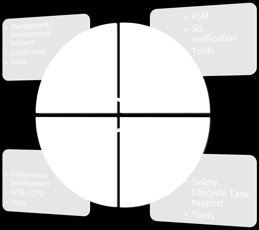
7 Main Product / Service Categories Consulting Process Safety (IEC 61511, IEC 62061, ISO 26262) Alarm Management Control System Security (ISA S99) Engineering Tools exsilentia (PHAx, SIL Selection LOPAx SRS SIL Verification) Safety Case FMEDA SILAlarm SILStat Product Certification Functional Safety (IEC 61508) Control System Cyber- Security Network Robustness (Achilles) Training Process Safety Control System Security Onsite Offsite Security Development Alarm Management Reference Materials Databases Tutorials Textbooks Reference Books Market Studies Professional Certification CFSE CFSP Includes: -Automotive -CACE/CACS -Hardware -Machinery -Process -Software CyberPHAx Processes - Products - People 7

8 exida Certification exida has established schemes for functional safety and cybersecurity certification of Systems, Products, Components, and Personnel. Functional Safety Certification involves a detailed analysis of both the engineering process and design margins resulting in random failure rate in all failure modes. Cybersecurity Certification involves a detailed analysis of the engineering process, cyber defense mechanisms, and network robustness. 8


9 Reference Materials exida authored most industry references for automation safety and reliability exida authored industry data handbook on equipment failure data exida authored the most comprehensive book on functional safety in the market 9
 SILStat (Field")
10 exsilentia PHAx (HAZOP) LOPAx Engineering Tools Layer of Protection database built-in SIL Selection Risk Matrix or Risk Graph Tolerable Frequency Basis Safety Requirements Specification SIL Verification Instrumentation failure database built-in Variables include reality test coverage, service Proof Test Generator Life Cycle Cost Analysis SILAlarm (Alarm Rationalization) SILStat (Field Failure Data Collection and Analysis) Proof Test & Maintenance Activity scheduling Process demand recording Failure recording CyberPHAx (Cyber Risk Assessment) 10
11 Topics What happens in an exida certification? How to find a safety integrity level How is SIL used? What this means for the manufacturer? What is SIL Capability? How to calculate SIL How to reach a certain rating Is there a way to improve a SIL rating?
12 WHAT HAPPENS IN AN EXIDA CERTIFICATION? 12
13 Certification Process 1. Kickoff Meeting 2. Perform FMEDA Analysis on Product 3. Creation of the Proven-In-Use Analysis 4. Process Analysis 5. Onsite audit 6. Certification Audit
14 IEC Full Certification The end result of the certification process is a certificate listing the SIL level for which a product is qualified and the standards that were used for the certification. However, we must understand that some products are certified with restrictions. The restrictions essentially indicate when a product does not meet some requirements of IEC The restrictions are listed in the safety manual and must be followed if safe operation is required. 14
15 HOW TO FIND A SAFETY INTEGRITY LEVEL 15
16 The SIL level of a product is determined by three things: 1. The Systematic Capability Rating 2. The Architectural Constraints for the element 3. The PFDavg calculation for the product. 16
17 Compliance Requirements SIL Capability Compliance Architectural Constraints Probability of Failure February 19,
18 THE SYSTEMATIC CAPABILITY 18
19 The Systematic Capability Systematic Capability is established by having your quality management system audited per IEC If the QMS meets the requirements of a SIL Capability rating is issued. The rating achieved depends on the effectiveness of your QMS. The certificate is for the systematic capability of a product. 19
20 THE ARCHITECTURAL CONSTRAINTS 20
21 The Architectural Constraints Architectural constraints are established by following Route 1H or Route 2H. Route 1H involves calculating the Safe Failure Fraction for the element. A valve is typically one component of the final element of a safety instrumented function (SIF). 21
22 Architectural Constraints from FMEDA Results Route 1 H - Safe Failure Fraction (SFF) according to of IEC Safe Failures Safe + Dangerous Failures Route 2 H - Assessment of the reliability data for the entire element according to of IEC
23 Route 1 H TYPE A Safe Failure Fraction Hardware Fault Tolerance < 60% SIL1 SIL2 SIL3 60% < 90% SIL2 SIL3 SIL4 90% < 99% SIL3 SIL4 SIL4 > 99% SIL3 SIL4 SIL4 Hardware Fault Tolerance = 1 (61508) The quantity of failures that can be tolerated while maintaining the safety function. 23
24 Route 2 H Table Type A Low Demand Applications Hardware Fault Tolerance SIL2 SIL3 SIL4 Type B elements using Route 2 H shall have a diagnostic coverage not less than 60%. 24
25 THE PFDAVG CALCULATION 25
26 The PFDavg calculation The PFDavg is based on the dangerous failure rate, system diagnostics, proof test coverage and test intervals. Typically, a final element assembly will have a PFDavg the only meets SIL 1. However, there are things that can be done with the diagnostics and proof test that would improve the PFDavg to SIL 2. 26
27 HOW IS SIL USED? 27
28 Safety Integrity Level Used FOUR ways: Safety Integrity Level SIL 4 SIL 3 SIL 2 SIL 1 1. To establish risk reduction requirements 2. Probabilistic limits for hardware random failure 3. Architectural constraints 4. To establish systematic capability 28
29 TO ESTABLISH RISK REDUCTION 29
30 Example of Risk Reduction PHA Determines that a specific hazard can occur every 10 years causing a major release of toxic fumes into the atmosphere. Determine the RRF for the hazard to occur once in 500 years. RRF = 500/10 = 50 30
31 Safety Integrity Level Safety Integrity Level Risk Reduction Factor SIL 4 SIL 3 SIL 2 SIL to to to to Each safety function has a requirement to reduce risk. SIL level - Order of magnitude level of risk reduction required 31
32 TO SET PROBABILISTIC LIMITS FOR HARDWARE RANDOM FAILURE 32
 SIL")

33 Safety Integrity Levels Random Failure Probability Safety Integrity Level Probability of failure on demand (Demand mode of operation) SIL 4 SIL 3 SIL 2 SIL 1 >=10-5 to <10-4 >=10-4 to <10-3 >=10-3 to <10-2 >=10-2 to < To set probabilistic limits for hardware random failure 33
34 Random Failure Probability Factors 1. Dangerous Undetected Failure Rate (FMEDA) 2. Proof Test Coverage 3. Proof Test Interval 4. Mission Time PFDavg = (PTC)*DU*TI/2 + (1-PTC)*DU*MT/2 Where PTC = Proof Test Coverage DU = Dangerous Undetected Failures TI = Proof Test Interval MT= Mission Time 34
35 Random vs. Systematic Faults Random Failures A failure occurring at a random time, which results from one or more of degradation mechanisms. Systematic Failures A failure related in a deterministic way to a certain cause, which can only be eliminated by a modification of the design or of the manufacturing process, operational procedures, documentation, or other relevant factors.
36 Random vs. Systematic Faults Specification of requirements, design, implementation Well Designed System, the system is correct Random Failure The system is not correct Systematic Fault Improperly Designed System, the system is not correct The system has a failure
37 Stress Strength: Failures All failures occur when stress exceeds the associated level of strength. Stress is usually a combination of "stressors." Heat Humidity Shock Vibration Electrical Surge Electro-Static Discharge Radio Frequency Interference Mis-calibration Maintenance Errors Operational Errors
38 Stress - Strength: Failures Stress Strength Strength varies with time and with other stress. Stress also varies with time. However they can be represented by probability distributions.
39 Stress - Strength: Failures At some point in time, Strength decreases and the failure rate increases rapidly this causes wear-out.
40 Stress - Strength: Failures Failure rate Time Stress-strength explains how failure rates vary with time Weak units from a production population fail early. This portion of the curve is known as infant mortality. When weak units are eliminated from the population stress-strength indicates a steady but declining failure rate. When strength declines, the failure rate increases significantly.
41 Stress - Strength: Failures Failure rate Area where IEC is applied Useful Life in listed in Safety Manuals End of Useful Life Time Note: Constant Failure Rate during Useful Life
42 Terms Low Demand Mode Where the frequency of demands for operation made on a safetyrelated system is no greater than one per year and no greater than twice the proof test frequency; Part 4, If the ratio of diagnostic test rate to demand rate exceeds 100, then the subsystem can be treated... As low demand mode..., Part 2, Note 2..the diagnostic test interval will need to be considered directly in the reliability model if it is not at least an order of magnitude less than the expected demand rate, Part 2, , Note 3 exida definition: A dangerous condition (a demand) occurs infrequently and at least 2X less often than manual proof testing. [Therefore proof testing can be given credit for risk reduction.]
43 Safety Integrity Levels Low Demand Random Failure Probability Safety Integrity Level Probability of failure on demand (Demand mode of operation) SIL 4 SIL 3 SIL 2 SIL 1 >=10-5 to <10-4 >=10-4 to <10-3 >=10-3 to <10-2 >=10-2 to <10-1
44 Safety Integrity Levels High Demand Random Failure Probability Safety Integrity Level Probability of dangerous failure per hour (Continuous mode of operation) SIL 4 SIL 3 SIL 2 SIL 1 >=10-9 to <10-8 >=10-8 to <10-7 >=10-7 to <10-6 >=10-6 to <10-5 High Demand Mode Where the frequency of demands for operation made on a safety-related system is greater than twice the proof check frequency;
45 ARCHITECTURAL CONSTRAINTS 45
46 SFF Product Types TYPE A A subsystem can be regarded as type A if, for the components required to achieve the safety function a) the failure modes of all constituent components are well defined; and b) the behavior of the subsystem under fault conditions can be completely determined; and c) there is sufficient dependable failure data from field experience to show that the claimed rates of failure for detected and undetected dangerous failures are met. TYPE B everything else! IEC 61508, Part 2, Section
47 IEC Safe Failure Fraction TYPE A Low Demand Applications Safe Failure Fraction Hardware Fault Tolerance < 60% SIL1 SIL2 SIL3 60% < 90% SIL2 SIL3 SIL4 90% < 99% SIL3 SIL4 SIL4 > 99% SIL3 SIL4 SIL4 Hardware Fault Tolerance = 1 (61508) The quantity of failures that can be tolerated while maintaining the safety function.
48 Route 2 H Table Type A Low Demand Applications Hardware Fault Tolerance SIL2 SIL3 SIL4 Type B elements using Route 2 H shall have a diagnostic coverage not less than 60%. 48
49 IEC Safe Failure Fraction TYPE B Safe Failure Fraction Hardware Fault Tolerance < 60% Not Allowed SIL1 SIL2 60% < 90% SIL1 SIL2 SIL3 90% < 99% SIL2 SIL3 SIL4 > 99% SIL3 SIL4 SIL4 Hardware Fault Tolerance = 1 (61508) The quantity of failures that can be tolerated while maintaining the safety function.
50 TO ESTABLISH SYSTEMATIC CAPABILITY 50


51 Safety Integrity Level Safety Integrity Level SIL 4 SIL 3 SIL 2 SIL 1 3) To establish systematic capability The equipment used to implement any safety function must be designed using procedures intended to prevent systematic design errors. The rigor of the required procedure is a function of SIL level.
52 Safety Integrity Levels Safety Integrity Level Probability of failure on demand (Demand mode of operation) Risk Reduction Factor SIL 4 SIL 3 SIL 2 SIL 1 >=10-5 to <10-4 >=10-4 to <10-3 >=10-3 to <10-2 >=10-2 to < to to to to 10
53 Safety Integrity Levels Safety Integrity Level SIL 4 SIL 3 SIL 2 SIL 1 Probability of dangerous failure per hour (Continuous mode of operation) >=10-9 to <10-8 >=10-8 to <10-7 >=10-7 to <10-6 >=10-6 to <10-5
54 61508 Annexes: Tables All Numbered Measures Are Required (No Pick and Choose) All Sub-alphabetized Measures are substitutable and partly combinable Technical / Measure SIL2 SIL3 1 Fault detection and diagnosis R HR 2 Error detecting and correcting codes R R 3a Failure assertion programming R R 3b Safety bag techniques R R 3c Diverse programming R R R - Recommended (Not using the measure requires a Ra4onale) HR - Highly Recommended (MUST)
55 COMPLETE COMPLIANCE 55

56 IEC Full Certification 56


57 Compliance Requirements SIL Capability Compliance Architectural Constraints Probability of Failure February 19,
58 EXAMPLE 58
59 exsilentia Example 59
60 exsilentia Example 60
61 HOW CAN I IMPROVE MY SIL? 61
62 How can I improve my SIL? SIL Capability Compliance Architectural Constraints Probability of Failure 1. Improve SIL Capability 2. Improve Architectural Constraints 3. Improve PFDavg 62
63 How can I improve my SIL? 1. Improve SIL Capability Improve effectiveness of internal quality management 2. Improve Architectural Constraints 1oo2 2oo3 Change your Hardware Fault Tolerance 3. Improve PFDavg Decrease Proof test interval Decrease Mission time Change the architecture Revise Proof test coverage 63
64 excellence in dependable automation Further questions? me: February 19,
Solenoid Valves used in Safety Instrumented Systems
 I&M V9629R1 Solenoid Valves used in Safety Instrumented Systems Operating Manual in accordance with IEC 61508 ASCO Valves Page 1 of 7 Table of Contents 1 Introduction...3 1.1 Terms and Abbreviations...3
Pneumatic QEV. SIL Safety Manual SIL SM Compiled By : G. Elliott, Date: 8/19/2015. Innovative and Reliable Valve & Pump Solutions
 SIL SM.0010 1 Pneumatic QEV Compiled By : G. Elliott, Date: 8/19/2015 Contents Terminology Definitions......3 Acronyms & Abbreviations..4 1. Introduction 5 1.1 Scope 5 1.2 Relevant Standards 5 1.3 Other
DeZURIK Double Block & Bleed (DBB) Knife Gate Valve Safety Manual
 Knife Gate Valve Safety Manual") Double Block & Bleed (DBB) Knife Gate Valve Safety Manual Manual D11044 September, 2015 Table of Contents 1 Introduction... 3 1.1 Terms... 3 1.2 Abbreviations... 4 1.3 Product Support... 4 1.4 Related
Double Block & Bleed (DBB) Knife Gate Valve Safety Manual Manual D11044 September, 2015 Table of Contents 1 Introduction... 3 1.1 Terms... 3 1.2 Abbreviations... 4 1.3 Product Support... 4 1.4 Related
FP15 Interface Valve. SIL Safety Manual. SIL SM.018 Rev 1. Compiled By : G. Elliott, Date: 30/10/2017. Innovative and Reliable Valve & Pump Solutions
 SIL SM.018 Rev 1 FP15 Interface Valve Compiled By : G. Elliott, Date: 30/10/2017 FP15/L1 FP15/H1 Contents Terminology Definitions......3 Acronyms & Abbreviations...4 1. Introduction...5 1.1 Scope.. 5 1.2
Solenoid Valves For Gas Service FP02G & FP05G
 SIL Safety Manual SM.0002 Rev 02 Solenoid Valves For Gas Service FP02G & FP05G Compiled By : G. Elliott, Date: 31/10/2017 Reviewed By : Peter Kyrycz Date: 31/10/2017 Contents Terminology Definitions......3
Bespoke Hydraulic Manifold Assembly
 SIL SM.0003 1 Bespoke Hydraulic Manifold Assembly Compiled By : G. Elliott, Date: 12/17/2015 Contents Terminology Definitions......3 Acronyms & Abbreviations..4 1. Introduction 5 1.1 Scope 5 1.2 Relevant
Section 1: Multiple Choice Explained EXAMPLE
 CFSP Process Applications Section 1: Multiple Choice Explained EXAMPLE Candidate Exam Number (No Name): Please write down your name in the above provided space. Only one answer is correct. Please circle
DeZURIK. KGC Cast Knife Gate Valve. Safety Manual
 KGC Cast Knife Gate Valve Safety Manual Manual D11036 August 29, 2014 Table of Contents 1 Introduction... 3 1.1 Terms... 3 1.2 Abbreviations... 4 1.3 Product Support... 4 1.4 Related Literature... 4 1.5
Eutectic Plug Valve. SIL Safety Manual. SIL SM.015 Rev 0. Compiled By : G. Elliott, Date: 19/10/2016. Innovative and Reliable Valve & Pump Solutions
 SIL SM.015 Rev 0 Eutectic Plug Valve Compiled By : G. Elliott, Date: 19/10/2016 Contents Terminology Definitions......3 Acronyms & Abbreviations...4 1. Introduction..5 1.1 Scope 5 1.2 Relevant Standards
Failure Modes, Effects and Diagnostic Analysis
 Failure Modes, Effects and Diagnostic Analysis Project: Surge Protective Devices D9324S Customer: G.M. International s.r.l Villasanta Italy Contract No.: GM 16/02-055 Report No.: GM 16/02-055 R005 Version
Hydraulic (Subsea) Shuttle Valves
 Shuttle Valves") SIL SM.009 0 Hydraulic (Subsea) Shuttle Valves Compiled By : G. Elliott, Date: 11/3/2014 Contents Terminology Definitions......3 Acronyms & Abbreviations..4 1. Introduction 5 1.1 Scope 5 1.2 Relevant Standards
SIL SM.009 0 Hydraulic (Subsea) Shuttle Valves Compiled By : G. Elliott, Date: 11/3/2014 Contents Terminology Definitions......3 Acronyms & Abbreviations..4 1. Introduction 5 1.1 Scope 5 1.2 Relevant Standards
DeZURIK. KSV Knife Gate Valve. Safety Manual
 KSV Knife Gate Valve Safety Manual Manual D11035 August 29, 2014 Table of Contents 1 Introduction... 3 1.1 Terms... 3 1.2 Abbreviations... 4 1.3 Product Support... 4 1.4 Related Literature... 4 1.5 Reference
Section 1: Multiple Choice
 CFSP Process Applications Section 1: Multiple Choice EXAMPLE Candidate Exam Number (No Name): Please write down your name in the above provided space. Only one answer is correct. Please circle only the
SPR - Pneumatic Spool Valve
 SIL SM.008 Rev 7 SPR - Pneumatic Spool Valve Compiled By : G. Elliott, Date: 31/08/17 Contents Terminology Definitions:... 3 Acronyms & Abbreviations:... 4 1.0 Introduction... 5 1.1 Purpose & Scope...
RESILIENT SEATED BUTTERFLY VALVES FUNCTIONAL SAFETY MANUAL
 Per IEC 61508 and IEC 61511 Standards BRAY.COM Table of Contents 1.0 Introduction.................................................... 1 1.1 Terms and Abbreviations...........................................
TRI LOK SAFETY MANUAL TRI LOK TRIPLE OFFSET BUTTERFLY VALVE. The High Performance Company
 TRI LOK TRI LOK TRIPLE OFFSET BUTTERFLY VALVE SAFETY MANUAL The High Performance Company Table of Contents 1.0 Introduction...1 1.1 Terms and Abbreviations... 1 1.2 Acronyms... 1 1.3 Product Support...
Failure Modes, Effects and Diagnostic Analysis
 Failure Modes, Effects and Diagnostic Analysis Project: Solenoid Valves SNMF 532 024 ** ** and SMF 52 024 ** ** Customer: ACG Automation Center Germany GmbH & Co. KG Tettnang Germany Contract No.: ACG
Failure Modes, Effects and Diagnostic Analysis
 Failure Modes, Effects and Diagnostic Analysis Project: Abc. X Series Ball Valve Company: Abc. Inc. Sellersville, PA USA Contract Number: Q11/12-345 Report No.: Abc 11/12-345 R001 Version V1, Revision
Failure Modes, Effects and Diagnostic Analysis
 Failure Modes, Effects and Diagnostic Analysis Project: Contact elements Type 8082 and Type 8208 with or without 8602 actuator Customer: R. STAHL Schaltgeräte GmbH Waldenburg Germany Contract No.: Stahl
Achieving Compliance in Hardware Fault Tolerance
 Mirek Generowicz FS Senior Expert (TÜV Rheinland #183/12) Engineering Manager, I&E Systems Pty Ltd Abstract The functional safety standards ISA S84/IEC 61511 (1 st Edition, 2003) and IEC 61508 both set
Failure Modes, Effects and Diagnostic Analysis
 Failure Modes, Effects and Diagnostic Analysis Project: Isolating repeater 9164 Customer: R. STAHL Schaltgeräte GmbH Waldenburg Germany Contract No.: STAHL 16/08-032 Report No.: STAHL 16/08-032 R032 Version
This manual provides necessary requirements for meeting the IEC or IEC functional safety standards.
 Instruction Manual Supplement Safety manual for Fisher Vee-Ball Series Purpose This safety manual provides information necessary to design, install, verify and maintain a Safety Instrumented Function (SIF)
The Key Variables Needed for PFDavg Calculation
 Iwan van Beurden, CFSE Dr. William M. Goble, CFSE exida Sellersville, PA 18960, USA wgoble@exida.com July 2015 Update 1.2 September 2016 Abstract In performance based functional safety standards, safety
SIL explained. Understanding the use of valve actuators in SIL rated safety instrumented systems ACTUATION
 SIL explained Understanding the use of valve actuators in SIL rated safety instrumented systems The requirement for Safety Integrity Level (SIL) equipment can be complicated and confusing. In this document,
Failure Modes, Effects and Diagnostic Analysis
 Failure Modes, Effects and Diagnostic Analysis Project: Primary Elements Company: Rosemount Inc. (an Emerson Process Management company) Chanhassen, MN USA Contract Number: Q13/04-008 Report No.: ROS 13/04-008
Failure Modes, Effects and Diagnostic Analysis
 Failure Modes, Effects and Diagnostic Analysis Project: Emerson s Rosemount 2051 Pressure Transmitter with 4-20mA HART Device Label SW 1.0.0-1.4.x Company: Rosemount Inc. Shakopee, MN USA Contract No.:
Safety manual for Fisher GX Control Valve and Actuator
 Instruction Manual Supplement GX Valve and Actuator Safety manual for Fisher GX Control Valve and Actuator Purpose This safety manual provides information necessary to design, install, verify and maintain
Ultima. X Series Gas Monitor
 Ultima X Series Gas Monitor Safety Manual SIL 2 Certified " The Ultima X Series Gas Monitor is qualified as an SIL 2 device under IEC 61508 and must be installed, used, and maintained in accordance with
Reliability of Safety-Critical Systems Chapter 3. Failures and Failure Analysis
 Reliability of Safety-Critical Systems Chapter 3. Failures and Failure Analysis Mary Ann Lundteigen and Marvin Rausand mary.a.lundteigen@ntnu.no RAMS Group Department of Production and Quality Engineering
Failure Modes, Effects and Diagnostic Analysis
 Failure Modes, Effects and Diagnostic Analysis Project: Ground Monitoring Device 71**/5, 81**/5, 82**/5 Company: R. STAHL Schaltgeräte GmbH Waldenburg Germany Contract No.: STAHL 11/07-089 Report No.:
Implementing IEC Standards for Safety Instrumented Systems
 Implementing IEC Standards for Safety Instrumented Systems ABHAY THODGE TUV Certificate: PFSE-06-607 INVENSYS OPERATIONS MANAGEMENT What is a Safety Instrumented System (SIS)? An SIS is designed to: respond
L&T Valves Limited SAFETY INTEGRITY LEVEL (SIL) VERIFICATION FOR HIGH INTEGRITY PRESSURE PROTECTION SYSTEM (HIPPS) Report No.
 VERIFICATION FOR HIGH INTEGRITY PRESSURE PROTECTION SYSTEM (HIPPS) Report No.") L&T Valves Limited TAMIL NADU SAFETY INTEGRITY LEVEL (SIL) VERIFICATION FOR HIGH INTEGRITY PRESSURE PROTECTION SYSTEM (HIPPS) MAY 2016 Report No. 8113245702-100-01 Submitted to L&T Valves Ltd. Report by
L&T Valves Limited TAMIL NADU SAFETY INTEGRITY LEVEL (SIL) VERIFICATION FOR HIGH INTEGRITY PRESSURE PROTECTION SYSTEM (HIPPS) MAY 2016 Report No. 8113245702-100-01 Submitted to L&T Valves Ltd. Report by
Failure Modes, Effects and Diagnostic Analysis. Rosemount Inc. Chanhassen, MN USA
 Failure Modes, Effects and Diagnostic Analysis Project: 3095MV Mass Flow Transmitter Customer: Rosemount Inc. Chanhassen, MN USA Contract No.: Q04/04-09 Report No.: Ros 04/04-09 R001 Version V1, Revision
Neles trunnion mounted ball valve Series D Rev. 2. Safety Manual
 Neles trunnion mounted ball valve Series D Rev. 2 Safety Manual 10SM D en 1/2017 2 Neles trunnion mounted ball valve, Series D Table of Contents 1 Introduction...3 2 Structure of the D series trunnion
Jamesbury Pneumatic Rack and Pinion Actuator
 Jamesbury Pneumatic Rack and Pinion Actuator Valv-Powr Series VPVL Rev. 3.0 Safety Manual 10SM VPVL en 5/2017 2 Jamesbury Pneumatic Rack and Pinion Actuator, Valv-Powr Series VPVL, Rev 3.0, Safety Manual
Failure Modes, Effects and Diagnostic Analysis
 Failure Modes, Effects and Diagnostic Analysis Project: Solenoid Drivers KFD2-SL2-(Ex)1.LK.vvcc KFD2-SL2-(Ex)*(.B).vvcc Customer: Pepperl+Fuchs GmbH Mannheim Germany Contract No.: P+F 06/09-23 Report No.:
Failure Modes, Effects and Diagnostic Analysis
 Failure Modes, Effects and Diagnostic Analysis Project: Digital Output Module Valve DOMV 9478/22-08-51 Company: R. STAHL Schaltgeräte GmbH Waldenburg Germany Contract No.: STAHL 11/01-104 Report No.: STAHL
Failure Modes, Effects and Diagnostic Analysis
 Failure Modes, Effects and Diagnostic Analysis Project: 3051S SIS Pressure Transmitter, with Safety Feature Board, Software Revision 3.0 Customer: Rosemount Inc. Chanhassen, MN USA Contract No.: Ros 02/11-07
Failure Modes, Effects and Diagnostic Analysis
 Failure Modes, Effects and Diagnostic Analysis Project: Temperature transmitter PR5337 / PR6337 / PR7501 with 4..20 ma output Customer: PR electronics A/S Rønde Denmark Contract No.: PR electronics A/S
Rosemount 2130 Level Switch
 Rosemount 2130 Level Switch Functional Safety Manual Manual Supplement Reference Manual Contents Contents 1Section 1: Introduction 1.1 Scope and purpose of the safety manual.............................................
New Thinking in Control Reliability
 Doug Nix, A.Sc.T. Compliance InSight Consulting Inc. New Thinking in Control Reliability Or Your Next Big Headache www.machinerysafety101.com (519) 729-5704 Control Reliability Burning Questions from the
Proof Testing A key performance indicator for designers and end users of Safety Instrumented Systems
 Proof Testing A key performance indicator for designers and end users of Safety Instrumented Systems EUR ING David Green BEng(hons) CEng MIET MInstMC RFSE Ron Bell OBE BSc CEng FIET Engineering Safety
Safety Manual VEGAVIB series 60
 Safety Manual VEGAVIB series 60 NAMUR Document ID: 32005 Contents Contents 1 Functional safety... 3 1.1 General information... 3 1.2 Planning... 4 1.3 Adjustment instructions... 6 1.4 Setup... 6 1.5 Reaction
Safety Manual VEGAVIB series 60
 Safety Manual VEGAVIB series 60 Contactless electronic switch Document ID: 32002 Contents Contents 1 Functional safety... 3 1.1 General information... 3 1.2 Planning... 4 1.3 Adjustment instructions...
Safety Manual OPTISWITCH series relay (DPDT)
") Safety Manual OPTISWITCH series 5000 - relay (DPDT) 1 Content Content 1 Functional safety 1.1 In general................................ 3 1.2 Planning................................. 5 1.3 Adjustment
Safety Manual OPTISWITCH series 5000 - relay (DPDT) 1 Content Content 1 Functional safety 1.1 In general................................ 3 1.2 Planning................................. 5 1.3 Adjustment
VALIDATE LOPA ASSUMPTIONS WITH DATA FROM YOUR OWN PROCESS
 Honeywell Advanced Materials new Low-Global-Warming Refrigerant Plant in Geismar, LA Tony Downes Sept 2018 VALIDATE LOPA ASSUMPTIONS WITH DATA FROM YOUR OWN PROCESS A little about the presenter 1 Led over
High performance disc valves Series Type BA, BK, BW, BM, BN, BO, BE, BH Rev Safety Manual
 High performance disc valves Series Type BA, BK, BW, BM, BN, BO, BE, BH Rev. 2.0 Safety Manual 10SM B Disc en 4/2018 2 High performance disc valves Series, Type BA, BK, BW, BM, BN, BO, BE, BH, Rev. 2.0
SIL Safety Manual for Fisherr ED, ES, ET, EZ, HP, or HPA Valves with 657 / 667 Actuator
 SIL Safety Manual ED, ES, ET, EZ, HP, HPA Valves w/ 657/667 Actuator SIL Safety Manual for Fisherr ED, ES, ET, EZ, HP, or HPA Valves with 657 / 667 Actuator Purpose This safety manual provides information
Failure Modes, Effects and Diagnostic Analysis. Rosemount Inc. Chanhassen, Minnesota USA
 Failure Modes, Effects and Diagnostic Analysis Project: 3051C Pressure Transmitter Customer: Rosemount Inc. Chanhassen, Minnesota USA Contract No.: Ros 03/10-11 Report No.: Ros 03/10-11 R001 Version V1,
Valve Communication Solutions. Safety instrumented systems
 Safety instrumented systems Safety Instrumented System (SIS) is implemented as part of a risk reduction strategy. The primary focus is to prevent catastrophic accidents resulting from abnormal operation.
SIL Safety Manual. ULTRAMAT 6 Gas Analyzer for the Determination of IR-Absorbing Gases. Supplement to instruction manual ULTRAMAT 6 and OXYMAT 6
 ULTRAMAT 6 Gas Analyzer for the Determination of IR-Absorbing Gases SIL Safety Manual Supplement to instruction manual ULTRAMAT 6 and OXYMAT 6 ULTRAMAT 6F 7MB2111, 7MB2117, 7MB2112, 7MB2118 ULTRAMAT 6E
Functional safety. Functional safety of Programmable systems, devices & components: Requirements from global & national standards
 Functional safety Functional safety of Programmable systems, devices & components: Requirements from global & national standards Matthias R. Heinze Vice President Engineering TUV Rheinland of N.A. Email
Safety Manual. Process pressure transmitter IPT-1* 4 20 ma/hart. Process pressure transmitter IPT-1*
 Safety Manual Process pressure transmitter IPT-1* 4 20 ma/hart Process pressure transmitter IPT-1* Contents Contents 1 Functional safety 1.1 General information... 3 1.2 Planning... 4 1.3 Instrument parameter
FULL STAINLESS STEEL EXPLOSION-PROOF SOLUTIONS OIL & GAS I OFFSHORE AND ONSHORE
 FULL STAINLESS STEEL EXPLOSION-PROOF SOLUTIONS OIL & GAS I OFFSHORE AND ONSHORE ASCO Numatics ASCO Numatics is the world leader in design, manufacturer of solenoid valves and accessories for both offshore
REASSESSING FAILURE RATES
 REASSESSING FAILURE RATES M. Generowicz, MIET, MIEAust, TÜV Rheinland FS Senior Expert A. Hertel, AMIChemE I&E Systems Pty Ltd SUMMARY In the context of process industries, automated safety functions are
Failure Modes, Effects and Diagnostic Analysis
 Failure Modes, Effects and Diagnostic Analysis Project: Variable area flow meter RAMC Customer: Rota Yokogawa GmbH & Co. KG Wehr Germany Contract No.: Rota Yokogawa 05/04-20 Report No.: Rota Yokogawa 05/04-20
Every things under control High-Integrity Pressure Protection System (HIPPS)
") Every things under control www.adico.co info@adico.co Table Of Contents 1. Introduction... 2 2. Standards... 3 3. HIPPS vs Emergency Shut Down... 4 4. Safety Requirement Specification... 4 5. Device Integrity
Every things under control www.adico.co info@adico.co Table Of Contents 1. Introduction... 2 2. Standards... 3 3. HIPPS vs Emergency Shut Down... 4 4. Safety Requirement Specification... 4 5. Device Integrity
Safety-critical systems: Basic definitions
 Safety-critical systems: Basic definitions Ákos Horváth Based on István Majzik s slides Dept. of Measurement and Information Systems Budapest University of Technology and Economics Department of Measurement
Reliability of Safety-Critical Systems Chapter 4. Testing and Maintenance
 Reliability of Safety-Critical Systems Chapter 4. Testing and Maintenance Mary Ann Lundteigen and Marvin Rausand mary.a.lundteigen@ntnu.no RAMS Group Department of Production and Quality Engineering NTNU
PROCESS AUTOMATION SIL. Manual Safety Integrity Level. Edition 2005 IEC 61508/61511
 PROCESS AUTOMATION Manual Safety Integrity Level SIL Edition 2005 IEC 61508/61511 With regard to the supply of products, the current issue of the following document is applicable: The General Terms of
Safety Manual VEGASWING 61, 63. NAMUR With SIL qualification. Document ID: 52084
 Safety Manual VEGASWING 61, 63 NAMUR With SIL qualification Document ID: 52084 Contents Contents 1 Document language 2 Scope 2.1 Instrument version... 4 2.2 Area of application... 4 2.3 SIL conformity...
Understanding safety life cycles
 Understanding safety life cycles IEC/EN 61508 is the basis for the specification, design, and operation of safety instrumented systems (SIS) Fast Forward: IEC/EN 61508 standards need to be implemented
The IEC61508 Inspection and QA Engineer s hymn sheet
 The IEC61508 Inspection and QA Engineer s hymn sheet A few key points for those inspectors and QA engineers involved with a project using the IEC61508 group of standards by the 61508 Association SAFETY
Special Documentation Proline Promass 80, 83
 SD00077D/06/EN/14.14 71272498 Products Solutions Services Special Documentation Proline Promass 80, 83 Functional safety manual Coriolis mass flow measuring system with 4 20 ma output signal Application
Accelerometer mod. TA18-S. SIL Safety Report
 Accelerometer mod. TA18-S SIL Safety Report SIL005/11 rev.1 of 03.02.2011 Page 1 of 7 1. Field of use The transducers are made to monitoring vibrations in systems that must meet particular technical safety
The Risk of LOPA and SIL Classification in the process industry
 The Risk of LOPA and SIL Classification in the process industry Mary Kay O Connor Process Safety Center International Symposium Beyond Regulatory Compliance, Making Safety Second Nature October 28-29,
YT-3300 / 3301 / 3302 / 3303 / 3350 / 3400 /
 Smart positioner YT-3300 / 3301 / 3302 / 3303 / 3350 / 3400 / 3410 / 3450 Series SIL Safety Instruction. Supplement to product manual July. 2015 YTC Ver 1.06 1 Table of contents 1 Introduction... 3 1.1
Continuous Gas Analysis. ULTRAMAT 6, OXYMAT 6 Safety Manual. Introduction 1. General description of functional safety 2
 Introduction 1 General description of functional safety 2 Continuous Gas Analysis ULTRAMAT 6, OXYMAT 6 Device-specific safety instructions 3 List of abbreviations A Operating Instructions Supplement to
Vibrating Switches SITRANS LVL 200S, LVL 200E. Safety Manual. NAMUR With SIL qualification
 Vibrating Switches SITRANS LVL 200S, LVL 200E NAMUR With SIL qualification Safety Manual Contents 1 Document language 2 Scope 2.1 Instrument version... 4 2.2 Area of application... 4 2.3 SIL conformity...
Rosemount 2120 Level Switch
 Rosemount 2120 Level Switch Functional Safety Manual Manual Supplement Manual Supplement Contents Contents 1Section 1: Introduction 1.1 Scope and purpose of the safety manual.............................................
High Integrity Pressure Protection Systems HIPPS
 High Integrity Pressure Protection Systems HIPPS HIPPS > High Integrity Pressure Protection Systems WHAT IS A HIPPS The High Integrity Pressure Protection Systems (HIPPS) is a mechanical and electrical
THE IMPROVEMENT OF SIL CALCULATION METHODOLOGY. Jinhyung Park 1 II. THE SIL CALCULATION METHODOLOGY ON IEC61508 AND SOME ARGUMENT
 THE IMPROVEMENT OF SIL CALCULATION METHODOLOGY Jinhyung Park 1 1 Yokogawa Electric Korea: 21, Seonyu-ro45-gil Yeongdeungpo-gu, Seoul, 07209, Jinhyung.park@kr.yokogawa.com Safety Integrity Level (SIL) is
Analysis of Instrumentation Failure Data
 Analysis of Instrumentation Failure Data A structured approach Standards Certification Education & Training Publishing Conferences & Exhibits Matthew F. (Matt) Murphy Senior Consultant, DuPont Engineering
Explaining the Differences in Mechanical Failure Rates: exida FMEDA Predictions and OREDA Estimations
 Explaining the Differences in Mechanical Failure Rates: exida FMEDA Predictions and OREDA Estimations Julia V. Bukowski, PhD Department of Electrical & Computer Engineering Villanova University Loren Stewart,
EL-O-Matic E and P Series Pneumatic Actuator SIL Safety Manual
 SIL Safety Manual DOC.SILM.EEP.EN Rev. 0 April 2017 EL-O-Matic E and P Series Pneumatic Actuator SIL Safety Manual schaal 1:1 EL Matic TM EL-O-Matic E and P Series DOC.SILM.EEP.EN Rev. 0 Table of Contents
H250 M9 Supplementary instructions
 H250 M9 Supplementary instructions Variable area flowmeter Safety manual acc. to IEC 61508:2010 KROHNE CONTENTS H250 M9 1 Introduction 3 1.1 Fields of application... 3 1.2 User benefits... 3 1.3 Relevant
Commissioning and safety manual
 Commissioning and safety manual CNL35L DNL35L SIL2 LOREME 12, rue des Potiers d'etain Actipole BORNY - B.P. 35014-57071 METZ CEDEX 3 Phone 03.87.76.32.51 - Telefax 03.87.76.32.52 Contact: Commercial@Loreme.fr
Knowledge, Certification, Networking
 www.iacpe.com Knowledge, Certification, Networking Page :1 of 71 Rev 01 Sept 2016 IACPE No 19, Jalan Bilal Mahmood 80100 Johor Bahru Malaysia The International of is providing the introduction to the Training
UNDERSTANDING SAFETY INTEGRITY LEVEL
 UNDERSTANDING SAFETY INTEGRITY LEVEL S p e c i a l A p p l i c a t i o n S e r i e s 2 THE NEW STANDARDS IN SAFETY On the morning of 12/11/05, the largest detonation since the end of WWII rocked the Buncefield
Transmitter mod. TR-A/V. SIL Safety Report
 Transmitter mod. TR-A/V SIL Safety Report SIL003/09 rev.1 del 09.03.2009 Pagina 1 di 7 1. Employ field The transmitters are dedicated to the vibration monitoring in plants where particular safety requirements
Reliability of Safety-Critical Systems Chapter 10. Common-Cause Failures - part 1
 Reliability of Safety-Critical Systems Chapter 10. Common-Cause Failures - part 1 Mary Ann Lundteigen and Marvin Rausand mary.a.lundteigen@ntnu.no &marvin.rausand@ntnu.no RAMS Group Department of Production
Session: 14 SIL or PL? What is the difference?
 Session: 14 SIL or PL? What is the difference? Stewart Robinson MIET MInstMC Consultant Engineer, Pilz Automation Technology UK Ltd. EN ISO 13849-1 and EN 6061 Having two different standards for safety
Functional Safety SIL Safety Instrumented Systems in the Process Industry
 Products Solutions Services Functional Safety SIL Safety Instrumented Systems in the Process Industry BASF - Press Photo 2 section Foreword rubric 3 Foreword has come into focus since the publication of
CHANGE HISTORY DISTRIBUTION LIST
 Issue Date of Issue CR/DR Numbers CHANGE HISTORY No. of Pages Draft A Aug 2011 N/A 28 Draft Issue Pages Changed and Reasons for Change Sept 2011 N/A 28 Formal issue with client comments from draft issue
Neles ValvGuard VG9000H Rev 2.0. Safety Manual
 Neles ValvGuard VG9000H Rev 2.0 Safety Manual 10SM VG9000H en 11/2016 2 Neles ValvGuard VG9000H Rev 2.0 Safety Manual Table of Contents 1 General information...3 1.1 Purpose of the document... 3 1.2 Description
The IEC61508 Project Manager's & Project Engineer's hymn sheet
 The IEC61508 Project Manager's & Project Engineer's hymn sheet A few key points for those project managers and project engineers undertaking a project using the IEC61508 group of standards by the 61508
CT433 - Machine Safety
 Rockwell Automation On The Move May 16-17 2018 Milwaukee, WI CT433 - Machine Safety Performance Level Selection and Design Realization Jon Riemer Solution Architect Safety & Security Functional Safety
What safety level can be reached when combining a contactor with a circuitbreaker for fail-safe switching?
 FAQ 01/2015 What safety level can be reached when combining a contactor with a circuitbreaker for fail-safe switching? SIRIUS Safety Integrated http://support.automation.siemens.com/ww/view/en/40349715
PREDICTING HEALTH OF FINAL CONTROL ELEMENT OF SAFETY INSTRUMENTED SYSTEM BY DIGITAL VALVE CONTROLLER
 PREDICTING HEALTH OF FINAL CONTROL ELEMENT OF SAFETY INSTRUMENTED SYSTEM BY DIGITAL VALVE CONTROLLER Riyaz Ali FIELDVUE Business Development Manager Fisher Controls Int'l., LLC. Marshalltown, IA 50158
Service & Support. Questions and Answers about the Proof Test Interval. Proof Test According to IEC FAQ August Answers for industry.
 Cover sheet Questions and Answers about the Proof Test Interval Proof Test According to IEC 62061 FAQ August 2012 Service & Support Answers for industry. Contents This entry originates from the Siemens
PL estimation acc. to EN ISO
 PL estimation acc. to EN ISO 3849- Example calculation for an application MAC Safety / Armin Wenigenrath, January 2007 Select the suitable standard for your application Reminder: The standards and the
What is Good Practice for the Proof Testing of Safety Instrumented Systems of Low Safety Integrity?
 SYMPOSIUM SRIS NO 59 HAZARDS IChem What is Good Practice for the Proof Testing of Safety Instrumented Systems of ow Safety Integrity? Jeff Wood BSc, Cng, FIMC, MIT, Ineos ChlorVinyls Runcorn Site, PO Box
DETERMINATION OF SAFETY REQUIREMENTS FOR SAFETY- RELATED PROTECTION AND CONTROL SYSTEMS - IEC 61508
 DETERMINATION OF SAFETY REQUIREMENTS FOR SAFETY- RELATED PROTECTION AND CONTROL SYSTEMS - IEC 61508 Simon J Brown Technology Division, Health & Safety Executive, Bootle, Merseyside L20 3QZ, UK Crown Copyright
YT-300 / 305 / 310 / 315 / 320 / 325 Series
 Volume Booster YT-300 / 305 / 310 / 315 / 320 / 325 Series SIL Safety Instruction. Supplement to product manual Apr. 2016 YTC Ver. 2.01 1 Table of contents 1 Introduction... 3 1.1 Purpose of this document...
The IEC61508 Operators' hymn sheet
 The IEC61508 Operators' hymn sheet A few key points for those Operators of plant or equipment that involve SIL rated safety functions*, trips or interlocks by The 61508 Association SAFETY INSTRUMENTED
Session One: A Practical Approach to Managing Safety Critical Equipment and Systems in Process Plants
 Session One: A Practical Approach to Managing Safety Critical Equipment and Systems in Process Plants Tahir Rafique Lead Electrical and Instruments Engineer: Qenos Botany Site Douglas Lloyd Senior Electrical
Safety Integrity Verification and Validation of a High Integrity Pressure Protection System (HIPPS) to IEC 61511
 to IEC 61511") Safety Integrity Verification and Validation of a High Integrity Pressure Protection System (HIPPS) to IEC 61511 Abstract Author: Colin Easton ProSalus Limited ~ Independent Safety Consultants A key requirement
Safety Integrity Verification and Validation of a High Integrity Pressure Protection System (HIPPS) to IEC 61511 Abstract Author: Colin Easton ProSalus Limited ~ Independent Safety Consultants A key requirement
Instrumented Safety Systems
 Instrumented Safety Systems Engineered Valve Systems for Control and Safety Applications HIPPS Final Elements DINO OLIVIERI Mokveld Agent AIS ISA Giornata di studio HIPPS Agenda The loop Final Elements
Transducer mod. T-NC/8-API. SIL Safety Report
 CEMB S.p.a. Transducer mod. T-NC/8-API SIL Safety Report SIL006/11 rev.0 dated 03.03.2011 Page 1 di 7 1. Employ field The transducers can measure the static or dynamic distance in plants which need to
Partial Stroke Testing. A.F.M. Prins
 Partial Stroke Testing A.F.M. Prins Partial Stroke Testing PST in a safety related system. As a supplier we have a responsibility to our clients. What do they want, and what do they really need? I like