Leak, Flow and Package Testing 101
|
|
|
- Roy Parker
- 6 years ago
- Views:
Transcription


1 Leak, Flow and Package Testing 101 Presented by TM Electronics, Inc.


2 Why is Testing important? Although Leak and Package Testing are different in their functional approach, the fundamental motivation for testing is the same - to insure that material that is supposed to remain in a package or product stays there, and that nothing in the outer environment that is not intended to get into the package or product can enter. You are taking this course because you are interested in basic leak, flow or package testing. Perhaps your product is designed to contain a material without losing any of the contents or to transfer a material or solution intact from one point to another. Perhaps you are introducing a new product that is itself enclosed in a completely sealed package, sterile or otherwise, to protect the product from the world, or to protect the world from your product. Whatever issue you are facing, it has become apparent that testing is important. Leaks mean product failure. Seal or closure weakness may lead to leaks. A leak or seal weakness may lead to material leakage, environmental contamination, loss of sterility or component failure. In all cases, leaks mean waste of manufactured product, and leaks that are not found will surely lead to customer complaints! 2
3 Course Syllabus Term One: Device / Product Integrity Testing What is a leak? Types of Leak Tests Pressure Decay Leak Testing Mass Flow Testing and Flow Testing for Occlusions/Obstructions. 17 Statistics for Quality and Process Control.. 19 Term Two: Package Testing Introduction to ANSI/AAMI/ISO Seal Strength Testing. 24 Restraining Plate Package Testing 27 Package Integrity Testing..29 Term Three: Non-Destructive Pressure/Vacuum Decay Chamber Testing for Sealed Products or Packages Surrogate Chamber Testing. 35 Understanding your Test Item..36 Designing your Test Chamber 37 Glossary of Terminology.. 42 Bibliography and References. 45 3
4 First Term Overview: Device or Product Integrity Testing Device or Product Whether you manufacture medical devices, auto parts, or other products, it is essential to provide assurance of product quality. Leak Integrity Testing Flow Integrity Testing Leak and flow testing are a valuable way to enable your QC department to provide assurance of your product s integrity. Small leaks Large leaks Pressure Decay Leak Test Mass Flow Test for Leakage Occlusion Testing Large or small leaks can be quantified using pressure decay and mass flow testing, and flow testing can also identify obstructions in flow-through parts. Leak Integrity Assurance Flow Integrity Assurance The end result is that you, the manufacturer, will gain CONTROL over your manufacturing process, and QUALITY ASSURANCE in the field. What is a Leak? In this section, we will discuss how leakage is measured and what is meant by Leak Rate. We will begin to look at the issue of determining the appropriate standard or specification for your particular product, and discuss the practical issues involving leakage including typical product leakage ( leak rate ), leak rate conversions and the price of no leaks. Although important and fundamental in leak science, most information in this section relates to the identification and measurement of leaks; package integrity testing will be discussed in detail later in the course. 4
5 Unit 1: What is a Leak? Simply and directly, a leak is a hole or a path through which the package contents may escape, or through which ambient materials from the environment may enter. There are holes in everything; the issue you face is to decide how large a hole must be to cause a failure, and where that hole is likely to be located. Your answer to these questions will help to determine what kind of leak testing is most appropriate for your product. There are two common methods of locating leaks: bubble testing, and sniffer testing with trace gas. We ll address these later in the class. A very important issue is the definition of the leakage or leak rate that must be found to avoid product failure, and this definition will vary according to your product and its circumstances. Remember that everything leaks, even if it is the permeation of gas molecules through a metal or plastic, or atoms leaking through a lead shield. It s just a matter of time. The important point is that leakage is relative to a standard or specification. In order to define the specification or standard (how much leakage is too much leakage?), and indeed in order to measure leakage at all, we need to understand one basic relationship: Leakage (or Leak Rate) = V t where V is the volume of the medium exiting or entering and t is the time period during which you are measuring the change in volume. Leak Rate is therefore the volume of material (air, fluid etc.) that escapes from a closed or sealed containment in a predetermined amount of time. You may see leak rate expressed in various units of measure, such as cc/min, cc/sec, or ft 3 /hr. The units will generally reflect whether you are measuring a relatively high or low leak rate; for example, leakage of air from a medical fluid container will be typically in the range of 1 x 10⁻³ cc/sec (quite small) but air leakage from a water pump may be in the moderately high range of 8-10 cc/min and still be considered an acceptable part based on its use and test specifications. We will discuss the setting of test specifications later in this course. Note that some people will use a leak measure as a change in pressure over time (psi/sec, kpa/sec). These measures represent the result of the volume leakage rate for that specific application. However, unless the total volume of the part and measuring system are known, these measurements cannot be standardized against other instruments or measuring systems. Using volumetric or mass measurements provides the best approach to defining leakage in a test system. Using the pressure drop method is most useful when a particular part can be identified as a good or bad part. Typical Product Leak Rates Having developed a very rudimentary sense of the meaning of Leak Rate, let us take a look at some practical issues involving actual products. The following table demonstrates typical leak rates for a variety of medical products. 5
6 TYPICAL ALLOWABLE AIR LEAKAGE FOR MEDICAL APPLICATIONS APPLICATION PRESSURE LEAK RATE CYCLE TIME Catheters 30 psig <1 cc/min (1.6 x 10⁻² cc/sec) 1 2 sec Balloon Catheters 200 psig 0.6 cc/min (1 x 10⁻² cc/sec) sec Blood Bags 2 psig 1 4 cc/min ( x 10-2 cc/sec) 4 10 sec Syringes psig cc/min (0.2-8 x 10⁻² cc/sec) 3-10 sec Insulin Tester Containers Medical Fluid Containers 1 x 10⁻⁴ cc/sec 1 x 10⁻³ cc/sec You may note that some items with higher allowable leak rates, such as the syringes, have a relatively short test time. This is related in part to the degree of flexibility of the test part. A less flexible test item such as a syringe may require less time to stabilize before the actual leak test begins, whereas a more flexible item such as a blood bag may need a longer settle time. This issue will be discussed in greater detail later in the class. Similarly, the table below illustrates typical product leakage in industrial applications. Note again that variations in test specifications vary depending on the type of part. Several have a relatively high level of leakage to reach the critical point, but others are lower in particular, the brake cylinders; consequently, a longer test time is needed to detect leakage at the desired critical level (remember our formula?). Another reason for variations in test time is the size of the part being tested. Even though the critical level of leak to be measured is larger, the volume of the part is larger. Most of these parts are not particularly flexible, as were many of the medical devices, but even these metal parts can be affected by temperature changes in the gas, and still need some stabilization time. In general, we can state that the lower the leakage rate, the longer the test time required. TYPICAL ALLOWABLE INDUSTRIAL PRODUCT LEAK RATE APPLICATION PRESSURE LEAK RATE CYCLE TIME Water Pumps 15 psig 4 6 cc/min sec Oil Pumps 30 psig 8 10 cc/min 5 10 sec Thermostats 80 psig 1 cc/min 2 sec Radiators psig 3 6 cc/min sec Brake Cylinders 80 psig 1 x 10⁻³ cc/sec 30 sec Hoses 150 psig 1 cc/min 10 sec Tube Sets 15 psig 2 cc/min 5 sec Faucets 80 psig 5 cc/min 15 sec. Fuel Injection Units 5 x 10⁻⁴ cc/sec Diesel Injection Units 1 x 10⁻² cc/sec Gas Filters 3 x 10⁻³ cc/sec Diesel Filters 3 x 10⁻² cc/sec Gas Pressure Regulators 3 x 10⁻² cc/sec Gas Tubes 3 x 10⁻³ cc/sec + high pressure test 6
7 Further Discussion: Leak Rate through an Orifice Leak Rate through an orifice a hole or a break is a function of several variables: the pressure differential across the orifice; the diameter or size of the hole; the density of the test medium; the temperature. The relationships can be defined as follows: Q = k * d 2 * Sqrt ( P 1 2 P 2 2 / ρ * T a ) where Q is flow rate, d is the diameter of the orifice, P 1 and P 2 are the pressure on either side of the orifice, ρ is the specific density of the medium, k is a dimensional constant and T is the temperature of the system. To obtain consistent measurements of leak rate, the temperature must be constant. When dealing with gases, most measurements assume it is used in a state where it is considered incompressible. Obviously, you can relate leakage with hole size, but several empirical factors are tied up in k. These factors come from geometry and fluid flow properties like the Reynolds number. Because of this, most leak rates are approximate, unless they are measured directly by mass flow. As an aside, because matter can flow through an orifice in either direction, in general, leak rates can be assessed using either pressure or vacuum. This is a part-related issue, and in making this decision you need to consider several points: the function of the part, the structural integrity of the part, the degree of pressure change needed to find the leak, and whether the part will outgas in a vacuum, giving false readings. Leak Rate Conversions A caveat to keep in mind when considering your test specifications: there are several common units of measure. The following tables give leakage and pressure conversion charts that may be helpful to you; note that these are volumetric leak rates at Standard Conditions stated 70 degrees Fahrenheit, 14.7 psia (1 atm). Leakage & Pressure Conversions All leak rate units are at standard atmosphere conditions (70 F, 14.7 psia) To Obtain cc/sec cc/min in 3 /min ft 3 /hr Pam 3 /sec Multiply cc/sec cc/min 1.67 x x x in 3 /min x ft 3 /hr Pam 3 /sec x
8 Be careful to note on your specifications or on specifications from others what their standard conditions are. Many will use 0 degrees Celsius as a reference. The SI units are Pam 3 /sec (P*V/t). Note also that the following are not leakage measurements (psi/sec, Pa/sec, mbar/sec), but are pressure rates. The actual leak rate is a function of volume. These pressure measurements are only good for one part design, at specific conditions. The Price of No Leaks We have now developed a sense of the relationship between the size of a leak that is critical and the sensitivity of the test needed to find it. Once you have determined the size of the critical leak for your particular part or device, you can make a determination of your test specifications, and you can begin to research the test method to best serve your needs. It is important to realize during this specification-setting period that there is a cost associated with instituting this quality control step. The table below shows a relative scale of different test methods. There are wide bands around each method to accommodate the different instrument type and the fixturing required to implement the test for your particular part. The Price of No Leaks 100,000 Relative leak testing equipment cost 60,000 30,000 10,000 5, Mass Flow Bubble Test Differential Pressure Gauge Pressure Decay Mass Spectrometry Trace Gas Leakage Measurement Sensitivity, std. cm 3 /sec As one would expect, the cost associated with greater sensitivity increases. If detection of very low leak rates is essential, the higher cost of equipment may be justified. Only you can analyze your own best interests. 8

9 Unit 2: Types of Leak Tests Bubble ( Dunk ) Testing Bubble testing is the simplest, least expensive method of detecting and assessing leak rate. The procedure is as the name implies: the part being tested is submerged in water, and the test operator visually observes and takes note of any bubbles escaping from the test part. Under the best test conditions, including good lighting, a very clear liquid, and a patient, alert operator, a leak rate of 10-2 to 10-3 sccs can be observed (a 1-2mm bubble escaping). Disadvantages include a long test time (a minimum of 30 seconds per test), water contamination, and part clean-up time. The sensitivity of the test is not high, due to operator dependence. Pressure Decay Testing Pressure decay testing measures the change in pressure between atmospheric pressure and your pressurized test sample. Unlike the bubble test, this test method yields quantitative information, hard Regulator data points that can be recorded and upon which decisions can be made. This removes the V2 V3 To Part dependency upon the operator and allows specific accept/reject criteria to be set, and this method is quite simple to use. It is reasonably fast; 2-4 second cycles are achievable, keeping in mind that test time is volume dependent. Although more sensitive than bubble testing, pressure decay testing is as To atm atm sensitive as the time available for the test. A variation uses a differential transducer for pressure on both sides of the membrane, which might give more sensitivity in some cases but adds more complication (differential pressure testing requires a reference volume, and is temperature dependent on both volumes; it is difficult or impossible to standardize ). Pressure decay may include vacuum testing since a vacuum is merely a pressure below atmosphere. We will return to Pressure Decay Testing frequently during this course. 9

10 Trace Gas Sensing There are several types of trace gas sensing systems on the market today. This diagram illustrates a simplified trace gas leak detector. The closed test part is pressurized with a tracer gas, and the sensor is moved around the part to determine if and where there is a detectable leakage of the tracer gas. A constant flow pump allows measurement of varying concentrations of gas. Of course, using this detector as a leak locator is easy, but using it as a quantitative leak detector requires skill! This instrument is also available for hazardous gases and work areas (intrinsically safe). This method Test Part gives quantitative measurements so standards can be precisely described. It is straightforward and reasonably easy to use, and the cost is low. However, because it is dependent on sensing a gas other than air, gas sensing is not useful for sealed packages that cannot be pressurized with a trace gas. Mass Flow Sensing Flow Diagram Flow Sensor Regulator V2 to part MT1 MT3 MT2 The Mass Flow test method uses a small sensor that heats air and then measures the change in temperature with regard to mass flow. Since mass flow is a function of the density of air, care must be taken to check that the calibration is for sea level pressure, otherwise small differences may occur from place to place. The mass flow detector is less sensitive to temperature changes than pressure decay. Mass flow meters vary in their response time depending on the level of leak rate; low rates can be longer especially if maximum values are exceeded. Mass Spectrometry Vacuum Chamber Helium Filled Part Leak Detector Test Port Mass Spectrometry is the most sensitive of all test methods, being capable of detecting sccs using helium. The helium-pressurized test part is placed in a chamber which is evacuated to a vacuum of 10-5 millibars, and any helium leakage is drawn into the mass spectrometer tube. The advantages to mass spectrometry include a very high level of sensitivity and a high degree of quantitative accuracy. However, mass spectrometry is extremely expensive, with equipment costs in the range of $25,000 - $100,000. The method is slow, and the cost to run and maintain the equipment is significant. 10
11 Types of Leak Tests Advantages and Disadvantages Below is a brief summary of several commonly used test methods, including advantages, disadvantages and the relative price of No Leaks. ADVANTAGES DISADVANTAGES APPROXIMATE SENSITIVITY RELATIVE COST Bubble ( Dunk ) Testing Simple Inexpensive Operator dependent/nonquantitative 10-2 to 10-3 sccs $100-$1,000 Low Cost, Trace Gas Best as leak Not usable for 10-4 to 10-5 sccs $3,000- Sensing locator sealed packages (helium) $10,000 Mass Flow Sensing Fast response Quantitative Ambient air pressure sensitive 10-2 to 10-3 sccs $4,000- $10,000 Pressure Decay Testing Quantitative 2-4 sec. Tests Sensitivity is dependent on part size and test time 10-4 to 10-6 sccs $5,000- $12,000 Mass Extremely sensitive Slow, high cost to run and maintain 10-9 to sccs Spectrometry $25,000- $100,000 11

12 Unit 3: Pressure or Vacuum Decay Leak Testing The Test Cycle Charge, Stabilize, Test and Handling Times Two Types of Leaks: Gross or Fine Choosing a Leak Rate Examples of Pressure/Vacuum Decay Leak Testers 12
13 Pressure Decay Leak Test Cycles What is happening during a leak test? The leak test cycle is actually broken down into three distinct phases, not counting the load and unload phases. The following diagram illustrates the relationship between these phases. The Leak Test Cycle CHARGE SETTLE TEST PRESSURE NONLEAKER Leak Limit LEAKER Load Unload TIME Load and Unload are the times it takes to engage and disengage your part or package from the pressurizing and pressure decay measuring instrument. Although not technically part of the actual test cycle time, these periods must be taken into account in order to realistically project the time needed to test individual items. Charge is the period of time in which the part is being pressurized to the predetermined test pressure (or slightly above this pressure, so any stability changes can be taken into account). Settle is the period allowed for the volume of the pressurized part or package to change and stabilize due to the stresses introduced by pressurization. This is particularly crucial in the case of flexible materials whose volume may change substantially with pressurization. If this is an issue for your product, you will want to review the discussion on restraining plate fixtures in a later unit of this course. The Settle period also allows time for the adiabatic temperature rise (the heat generated through compression of a gas) to stabilize. Test is the data taking period in which the measurement of the decay of pressure is taken. 13
14 Two Types of Leaks Decay is a term used for the difference in pressure from its initial state of complete pressurization to the pressure at the end of the test phase of the leak test cycle previously discussed. CHARGE SETTLE TEST Test Pressure Leak Limit Varying amounts of acceptable background pressure decay Typical fine leak failure Typical gross leak failure Once pressurized and stabilized, the test instrument will measure the decay of the pressure inside the test part or package over a predetermined period of time. As we have already learned, everything leaks; there will be some amount of apparent background leakage, even if only molecules permeating a rigid container. This pressure decay becomes more significant as the test time increases. This decay may be related to the physical or mechanical properties of the product as well. This tendency is an important consideration when setting the Leak Limit. If the part or package you are testing possesses a gross leak, as for example an unsealed joint, that prohibits complete pressurization, the test may not complete the Charge phase of the test cycle, and the test may be terminated at this point. If the part being tested can be completely pressurized but the decay of the internal pressure is greater than the expected background decay for that part, it may indicate an unacceptable level of leakage. This is a fine leak. The selection of an appropriate Leak Limit for the product being tested will differentiate between normal background pressure decay and an unacceptable fine leak in the test item. 14
15 Pressure Decay Testing: Choosing a Leak Rate Setting the Leak Limit The Leak Limit is set based on your need for sensitivity in detecting a pressure decay in your part or package that exceeds what has been determined to be normal, acceptable leakage. You want to convert your pressure decay ( P) to leak rate. The guiding equation is: Q (sccs) = P (atm) * V (cc) / t (sec) where Q, leak rate, is expressed in standard cubic centimeters per second; where t is the test time in seconds; The longer the test time, the smaller the leak rate you will be able to identify. Remember, we agreed that everything leaks; it s only a matter of time! When considering the test cycle for production times, don t forget to include all phases of the test cycle (Load, Charge, Settle, Test and Unload) see the unit on Pressure Decay Test Cycles for more information. and V is the internal volume of the pressurized system. Pressure decay sensitivity is also a volume function. When selecting your spec, remember to include all the volume in your test system the instrument, the fixture and your part in your calculations. To maximize the sensitivity of your test, it is also important to consider the stability of your instrument and its environmental conditions such as ambient temperature and temperature changes. However, most test cycles are short in seconds and temperature change may be negligible. EXAMPLE Let s consider an example. You have performed a pressure decay test on your part and found the pressure decay ( P) to be psi (.1 inh 2 O). This translates to 2.5x10⁻⁴ atm. Your part, plus the internal pressurized volume of the instrument and the fixture, has a volume of 100cc. Your test time was 10 seconds. Using our formula above, we calculate: Leak Rate = 2.5 x 10-4 atm * 100cc / 10 sec = 2.5 x 10⁻³ atm-cc/sec This is the leak rate for your part. Is it acceptable or a reject? That is a decision you must make as you set your Leak Limit. If this is your Leak Limit, then it is the maximum acceptable leak rate for your part and your Pressure Decay Test should reject any parts with a greater pressure decay at this test time. 15


16 TM Electronics, Inc. Leak and Flow Testers The TME SOLUTION Leak & Flow Tester The TME SOLUTION is a high resolution leak and flow tester featuring one to four channel concurrent or multiple channel sequential leak and flow testing. Sensitive, repeatable and reliable, the SOLUTION can be configured to perform ten different tests on product, including burst, occlusion, vacuum and pressure decay, crack, and differential pressure or vacuum. Touch screen menudrive operation allows the operator to control the test parameters, examine statistical analysis of results or download data files easily. The SOLUTION, in conjunction with custom fixtures, accessories and engineering support, provides a complete turnkey solution to your leak and flow testing problems. The TME INDUSTRIAL SOLUTION is available in a NEMA-4 enclosure for harsh environments. All TME Solution models are available with Ethernet capability. The TME WORKER Leak, Leak/Flow or Leak/Occlusion Tester The TME Worker is an affordable, every-day, highresolution ( psig) test instrument available as a pressure or vacuum tester. The Worker has a small footprint, fast response, and is easy to program and use. PLC controls for semi-automatic operation and two-way RS-232 communication capability for downloadable program selection and uploadable data is standard, and Ethernet connectivity is optional. 16

17 Unit 4: Mass Flow Testing and Flow Testing for Occlusions/Obstructions Mass Flow Testing for Leakage Flow Testing for Obstructions: Mass Flow Testing for Occlusions Back Pressure Occlusion Testing Pressure Drop Occlusion Testing 17
18 Mass Flow Testing for Leakage Mass flow testing uses intrinsic properties of air to directly measure the amount of air escaping a closed system. A pressure regulator establishes the testing pressure, and then the sensor records any movement of air out of the test system. Mass flows are not affected by temperature changes due to pressurization. Mass flow sensors have limited low range sensitivity, generally useable at greater than one sccm (.02 sccs). We have seen that either pressure decay or mass flow testing can be used for leak testing. What are the criteria for deciding which is appropriate for your particular need? Depending on the size of the leak you are searching for (and the volume of your product), mass flow leak testing can have several advantages, including speed of test. The mass flow test is not dependent on temperature change, which may be a difficulty for the pressure decay test. Flow Testing for Obstructions/Occlusions Mass flow testing Mass flow testing is available for identifying obstructions in an open-ended test part. Unlike mass flow testing for leakage, mass flow testing for obstructions uses a continual flow measure the blockage in an open-ended device, such as a medical catheter or refrigeration tubing. Once the pressure sensor has indicated that the test part has reached the proper pressure, the flow sensor measures the continuous flow of air through the sensor assembly. Determination of whether the part passes or fails the test is made based on the flow rate through the part. If the flow sensor measures too low a flow rate at the desired pressure, the part will fail the test. Any obstructions in the part, therefore, will restrict the flow of air through the device, thereby causing the part to fail the test. Back Pressure Occlusion Testing When a tube or device is pressurized with air, a flow will be established depending on the input pressure. If the flow path is obstructed, more pressure will be required to force flow through the product. Back pressure occlusion testing measures the input pressure to the device. A blockage creates a higher pressure at the device. The instrument measures the input pressure, and limits on the pressure measurement are set in the instrument based on experience with the obstructed part. A higher pressure indicates a blockage. Pressure Drop Occlusion Testing A device will often need to vent its pressure in a given period of time for proper function. Alternatively, a part may have a manufacturing defect that creates a flap or one-way obstruction that prevents air from venting the part. Pressure drop occlusion testing pressurizes the part, and then measures the change in pressure when the pressure is removed. The pressure must approach a value or zero in a fixed time. If the pressure does not drop a minimum amount, then the limit set in the instrument will not be met, thus indicating a blockage. 18

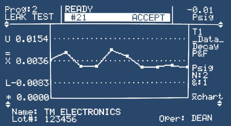
19 Unit 5: TME Statistics Packages: For Quality and Process Control TM Electronics leak testers and package testers contain a standard statistical package that provides not only quality documentation but also process control tools such as control charts, histograms and graphic presentation of each individual test. Control charts are commonly used to aid in manufacturing process control. The objective of control charts is to monitor the process in real time so if something goes wrong, it can be noted and corrected with the minimum of lost product. The concept behind control charts is as follows: 1. A process in control will result in pressure decay test values that fall consistently in a predictable range around the average (see Figure 1). In addition, the average test value will not change appreciably over time when the sealing process is in control. 2. Because processes always vary slightly due to manufacturing and material variations, good product test values will go up and down within a range around the mean value. That range can be statistically predicted using the mean test value plus and minus three standard deviations (a measure of the variation inherent in the process). The acceptable range is the Figure 1 Control charts for leak test results showing a process in control set of test values that fall between the upper and lower control limits. These control limits are automatically calculated in the TME test instrument from the previous test results in the Datalog. 3. In the TME Solution, the data points on the control chart consist of subgroups of test results. These subgroups can be as small as two tests (as in Figure 1), or as many as 20 tests. Subgroups are used to minimize the effect of a testing error or a single bad part. Control charts for the mean (X-bar) can help the manufacturer in several ways. If, for example, a temperature problem in your sealing equipment is causing weaker than usual seals resulting in greater pressure decay, the upward trend in test values will be obvious on the control chart even before the product reaches the point of failures. This gives the machine operator an opportunity to correct the temperature problem with little or no loss of product. Several data points outside of the control limits (Figure 2) may give the machine operator an indication that instability is developing in the process that needs to be investigated before a large quantity of bad product is produced. Control charts for range (the difference between the maximum test value and the minimum test value within a subgroup) also have a place in identifying when the process is becoming erratic and inconsistent. Figure 2 Control charts for process going out of control 19
20 Term Two: Package Testing 20
21 Second Term Overview: Package Testing Product Package Package integrity testing is the next step for the device or product manufacturer. Seal Strength Testing Leak Integrity Testing There are two roads of testing - seal strength testing and leak integrity testing for nonporous packages. Burst Testing Creep Testing Creep to Failure Test Pressure Decay Test Seal strength testing is valuable to ensure that package contents don t escape, and that sterile barriers remain intact, under stresses from transport, shelf life and normal usage. Seal Strength Assurance Sterile Integrity Assurance Having completed and documented your device and packaging testing, you can now present your final product to the market. 21
22 Unit 1: Introduction to ANSI/AAMI/ISO Essential for Medical Packaging, but Useful and Important Concepts for All ISO 11607, Packaging for Terminally Sterilized Medical Packaging, is an international standard providing a guideline for the design, processing and testing of primary product packages. Because the FDA considers ISO to be the paradigm for validation protocol for medical device packaging, it is important that manufacturers of these devices rely on guidance from this document as they seek FDA approval of their packaging system validation protocol. The concepts expressed in ISO are useful and helpful to non-medical device manufacturers, as well. Whether your product is food for people or pets, electronics, or automotive parts, if you package it, you could find some excellent guidance here. According to ISO 11607, the intention of packaging for terminally sterilized medical devices is to maintain the sterility of the product with respect to its intended use, the shelf life, transport, and storage conditions, i.e. to see that the packaging material and process provide a package that will withstand the sterilization and packaging processes and maintain that sterile barrier for the life of the product. This is a twofold objective: first, to ensure the integrity of the sealed package, and second, to assure that no weaknesses in the sealed areas of the package permit leaks to develop with handling stresses and time. To assure that the package performs adequately, you must be sure that the package is able to maintain the integrity of both the seals and the materials under stress. This implies that your package testing system must include both package integrity testing and seal strength testing, two complementary but very different procedures. Package integrity may be thought of as a leak test of the package is there a failure in the materials or process that allows contamination to enter? Seal strength testing, on the other hand, measures an attribute of the seal, which is designed to ensure that the seal presents a microbial barrier to at least the same extent as the rest of the packaging. Both testing streams are important in your final package analysis. These two paths can be illustrated as follows: Sterile Barrier System Integrity S tructural Integrity to Point of Use Sterility Integrity Process to Point of Use SEAL STRENGTH LEAK TEST Tensile Seal Strength ASTM F88 Inflation Seal Strength Destructive Testing Non- Destructive Testing ASTM F-1140 ASTM F-2054 Burst Test Creep or CTF Test Porous Material Non-Porous Material Porous Material Non-Porous Material 22
23 Consensus Standards? ASTM Test Methods? A note to medical device manufacturers and packagers: Before deciding on specific package test methods, it is important to look ahead to the process you, as medical device packaging professionals, will have to deal with: validation of your chosen package test method. What is a validatable test method? A validatable test method is one for which the following characteristics have been defined by ASTM or FDA: Repeatability: what is the variation in results using the same operator, same equipment, in the same location? Reproduceability: what is the variation in results with different operators using different equipment in varying locations? Sensitivity: what is the smallest value of the tested variable that can be accurately identified by the test method? Although you are not required to use a test method for which the above characteristics have already been defined and recognized by FDA, it is greatly to your advantage to do so. If you design your own test method, YOU will be responsible for all the effort that has been done by others, such as ASTM, for validatable methods! ASTM is a consensus body made up of OEM users, suppliers, instrument and other manufacturers. The ASTM process provides for the development of test methods using a standard procedure, and confirmation of methods using Interlaboratory Studies (ILS). These procedures provide the repeatability, reproduceability and sensitivity data necessary to validate your test method with your product. FDA Recognized Consensus Standards are by definition test methods developed by consensus bodies such as ASTM. For more information about FDA consensus standards, check the following government websites: for more information; for FAQ s. A note to the rest of you: You may or may not be responsible to the government for validation of your test methods for leak or package testing. However, you are of course responsible for providing the best possible protection for your product, your customers, and yourself by selecting the most appropriate test method for your needs. ASTM test methods, when appropriate to your product or package, provide information on repeatability, reproduceability and sensitivity that will enhance your confidence in the way you are testing your product. 23
24 Unit 2: Seal Strength Testing Types of Seal Strength Testing: F P P T OVR T Tensile Test T Whole Package Burst Test T Whole Package Creep Test Tensile Testing Tensile seal strength testing measures the ability of a package seal to resist separation the simple peel strength of the seal. Using a defined width sample of a package perimeter seal, a moving jaw pulls the sample apart at a constant speed while measuring the resistance force during the seal separation. The tensile test is particularly suited to peel-open packages. A significant advantage to this test is its sensitivity, and a disadvantage is that in the majority of cases a perimeter seal is sampled only at several locations and a total package seal strength measure is not obtained. Another disadvantage is that the effect of hoop and lateral stresses from inflation or non-perpendicular peel stress cannot be measured. 24
25 Inflation Seal Strength Testing Inflation seal strength testing includes burst, creep and creep-to-failure testing. This test requires pressurizing the entire package and measuring the peak rupture pressure (burst test) or the time to failure at a constantly held pressure (creep and creep-to-failure test). This test provides three different components of stress to the package: peel stress with horizontal and vertical components, tension due to hoop stress in the vertical direction, and lateral stress due to package expansion. If these stresses are greater than the strength of the seal at any point within the package, the seal will rupture. This provides a more realistic representation of stresses to which your package will be subject than that provided by the tensile test. Another advantage to this type of testing is that it provides a whole-package minimum seal strength and also indicates the weakest seal area, and is equally applicable to peelable and non-peelable seals. Inflation tests are applicable to most package forms such as pouches, header bags, lidded trays, flexible or rigid blisters and laminated or rolled tubes. Burst Testing Burst testing determines the overall minimum seal strength of the package seals by inflating the package at a uniform rate until the seal separates at the point of greatest weakness. The graph at left represents the output from the TM Electronics BT-1000 Automated Seal Strength Tester showing a characteristic burst curve. The Burst Test is a peak inflation pressure test; you can see how the pressure increases to a maximum pressure at which the pressure drops to zero. This drop represents the rupture of the seal. The pressure at which the package bursts (176.0 InH 2 O on our burst graph) is a variable statistic that can be utilized to document process development and process control through the use of tools such as upper and lower control limits. Typical Burst Test Graph Control of inflation rate is important in a burst test to ensure consistent conditions for the test method. The porosity (or lack thereof) of the package material determines the inflation rate for the burst test. Because air escapes through the walls of a porous package during inflation, the flow rate must be increased to compensate for the lost air through the walls and create the back pressure in the porous package. 25


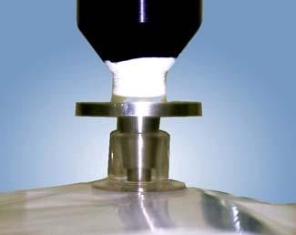
26 Creep Testing Creep Test The Creep Test is a second general type of whole package inflation seal strength test. In the Creep Test, a whole package is inflated to a constant pressure, which is then held for a specified time, resulting in a pass/fail result. This provides a test for slow shear of the adhesive bond similar to a dead weight hanging on the seal. A suggested starting pressure for peelable seals is to begin evaluating your seal with a creep pressure that is about 80% of the burst value. The inflation rate is not critical, as long as the initial fill is not so fast as to shock the seal or so slow as to result in an overly long test time. P T (sec) Test Over Shortcomings of this test are the need for the operator to visually examine the seal at the end of the test to determine the degree of seal peel, and the lack of a variable statistic upon which to perform process control analysis. Creep to Failure Testing This is a variation on the Creep Test that addresses its weaknesses. In the Creep-to-Failure test, the test pressure on the inflated package is held until the seal actually fails, yielding an end point value (a variable statistic), time to failure, and pinpointing the area of greatest weakness in the seal. Time to failure can then be used in SPC or SQC methods. Questions? How can I get the pressure into the package? To pressurize a closed package, a leak tight measuring path must be available between the package interior volume and the pressure source. Here we can see a simple, effective method of accomplishing this. This is the TM Electronics patented Package-Port system in which a reusable plastic entry port is secured and then accommodates the pressurizing probe. The probe tip pierces the package, enabling pressurization, and the Package-Port reinforces the package material to eliminate any possible leakage of gas around the penetration point. Inexpensive, simple to use and reliable, this system makes in-process package inflation testing highly efficient and repeatable. 26
27 Unit 3: Restraining Plate Package Testing Seal strength values are related to the package size, geometry, and materials. For example, pouches with a long side seal will generally fail on the long seal unless a heater failure has occurred on the shorter seal or chevron. Unsupported tray lid seals may fail at points only relative to their geometry. Very flexible package materials may deform with pressurization to an extent that makes seal testing difficult. To address these problems, it may be advisable to use restraining plates for your inflation testing. The geometry of the package under test affects the distribution of internal pressure forces on the package surface and seals; for example, a pouch-form package unrestrained in any axis exhibits circumferential hoop stress when internal pressure is applied. When the package is restrained, the load application is distributed directly on the seal area and, because material stretching and deformation is minimized, the test forces are more uniformly applied. The diagram below illustrates the effect of restraining plates on the pouch under test: where R is the radius, P is the pressure exerted on the unrestrained edges of the pouch, and Fy and Fx are the force vectors on the seal. Restraining Plate Test Forces on Pouch Average Burst Pressure (psi) U Gap (inches) In addition, package restraint has a direct relationship to burst pressures: the wider the gap between plates, the lower the average burst pressure (see graph). The most important factor when interpreting test results is that all conditions in the package test method are consistent. Establish a set of test conditions for each package and reproduce those conditions consistently. Use of package restraints must be approached with caution; because of pressures exerted on the plates, extreme care must be taken that fixtures are designed to withstand the forces applied by the inflated package. 27
28 Seal Strength Testing Summary Seal Strength Testing Inflation seal strength test results can be an excellent tool for process control. Burst test results, creep-to-failure and tensile data are all amenable to use in control charts and provide quantitative data required by ISO for package testing validation. A number of ASTM test methods, which are accepted FDA Consensus Standards, are available to aid in the design of these tests (see below). ASTM Seal Strength Test Methods Standard Test Methods for Internal Pressurization Failure Resistance of Unrestrained Packages Standard Test Method for Burst Testing of Flexible Package Seals Using Internal Air Pressurization Within Restraining Plates Standard Test Method for Seal Strength of Flexible Barrier Materials (Tensile Test) Reference # F F F But as we discussed earlier, seal strength testing is only half of the story. The other half is Physical Package Integrity Testing. 28
29 Unit 4: Package Integrity Testing We have thoroughly examined the need and methods of seal strength testing. Package integrity testing is purely a measure of the package s sterile barrier a leak test of the whole package. In addition to seal bonding failures or disrupted seals, leakage can be the result of large holes, pinholes or cracks in package materials. Either source of leakage represents the potential for product contamination elements of the ambient atmosphere outside of the package entering the package or for the materials inside the package to escape. Biological Challenge Tests vs. Physical Test Methods Biological challenge tests, in which the package is isolated in a chamber, surrounded by microbeladen atmosphere, and then examined after the microbes have been removed, are indicated by ISO for finished medical device packaging. Recent studies indicate that these high bio-burden aerosol tests may not be the most reliable indicators of leakage. Physical test methods, which are more reliable and more repeatable, present the best opportunity for determining the integrity of the package. AIR OUT AIR IN MICROBES Biological Challenge Test Set-up. The ISO List of methods for physical integrity tests includes these methods: Visual Inspection Method Internal Pressure Method Vacuum Leak Method Dye Penetration Method These methods have been reviewed and are recommended for use. A drawback of these methods is that they are not quantifiable, and that they require operator interpretation. The FDA has accepted certain test methods produced by industry consensus organizations as being valid for medical device packaging. This means they have been evaluated for repeatability, reproduceability and sensitivity, and make the validation process much easier for the medical packaging professional. These consensus standards are also an excellent place to start for those outside the medical packaging community as they begin the process of designing or selecting a package test method. The table below gives an overview of currently used package test methods, their ASTM test method designation if applicable, appropriate usage circumstances, advantages and disadvantages. Note: It is very important that you think about your package, your process and your end product s needs when evaluating test methods. Among other things, you should consider: - Are your barrier materials porous or non-porous? - Will you need to test the whole package, or just the seals? - Is a destructive test or a non-destructive test more suitable to your needs? - Are you able to consider an expensive test, or are you operating on a budget? 29
30 The Alternative to Microbial Challenge: Physical Tests with ASTM Test Methods Test Method Package Form Barrier Destructive Cost Sensitivity Or Non? Dye Penetration (Blue Dye Pouch, tray Porous or Destructive $ 50 um (.002 ) Test) ASTM F-1929 Non-porous channel leak Advantages: Inexpensive, commonly used test Disadvantages: Messy, operator dependent, requires clear material on at least one side, difficult to use with papers and some porous materials that can absorb dye; qualitative Visual Inspection Pouch, tray Porous or Destructive $ 75 um (.003 ) ASTM F-1886 Non-porous channels Advantages: Inexpensive, convenient Disadvantages: Dependent on operator, materials, magnification etc.; can t rule out pinholes; qualitative CO2 Tracer Gas Trays with Porous Non Destructive $$$ 100 um channel ASTM F-2228 porous lids 50 um hole Advantages: Not operator dependent; will find leaks in rigid tray material as well as channels in the seal Disadvantages: Not considered a whole package test; does not challenge the porous component of the package, limited use Bubble Emission Flexible material Non-Porous Destructive $$ 100 um hole or ASTM D x 10-5 cc/sec Advantages: Useful for gross leak detection; useable with a variety of package forms Disadvantages: May not detect small leaks; dependent on product contained, materials etc; Operator dependent, messy, qualitative CO2 Tracer Gas UNLIDDED Non-Porous Non Destructive $$$ 50 um (.002 ) ASTM F-2227 Rigid Trays pinholes Advantages: Not operator dependent Disadvantages: Not for whole package, applicable to empty trays only Pressure Decay with/without Flexible pouches, NonPorous Destructive $$ 25 um pinholes Restraining Plates ASTM F-2095 Foil sealed trays or 1 x 10⁻⁴ sccs Advantages: Quantitative, not operator dependent, fast, easy to use, wide range of applicability Disadvantages: Sensitivity dependent on package volume; doesn t show location of leaks; not amenable to porous barriers or liquid contents Bubble Test (Internal Flexible material Porous or Destructive $ 250 um hole Pressurization) ASTM F-2096 Non-porous Advantages: Useful for gross leak detection; useable with a variety of package forms; inexpensive Disadvantages: Messy, operator dependent, use with porous in certain circumstances only, long test time Vacuum Differential Trays (lid/no lid) Porous or Non Destructive $$$ Varies with ASTM F-2338 and cups Non-porous application Advantages: Not operator dependent, amenable to a variety of package forms and materials Disadvantages: Requires sealing of porous surfaces Helium Tracer Gas Flexible or Non-Porous Non Destructive $$$$ sccs ASTM F-2391 Rigid Packages Advantages: Quantitative, can detect moderate ( Sniffer Mode ) to very fine ( Vacuum Mode ) leaks Disadvantages: Expensive, nigh maintenance 30
31 Some Other Alternatives: Physical Integrity Tests in Use Test Method Package Form Barrier Destructive Cost Sensitivity Or Non? Pressure/Vacuum Decay Sealed, flexible Non-Porous Non-Destructive $$$ 5-10 um hole Chamber Test material Advantages: Quantitative, fast, not operator dependent, can be semi-automated or manual Disadvantages: Not a consensus standard; requires custom fixture for greatest sensitivity Ultrasonic Leak Pouches, flexible Porous or Non Destructive $$$$ 25 um Detection packages Non-porous Advantages: No sample preparation; detects non-leaking seal defects; fast Disadvantages: Not a consensus standard Force Decay Pouches Non-Porous Non Destructive $$$ um Advantages: Fast, quantitative, not operator dependent Disadvantages: Not a consensus standard; requires custom fixtures for greatest sensitivity 31

32 TM Electronics Package Testers TME S BT-1000 Package Tester is versatile, automated and able to perform both leak-integrity tests and a battery of seal-strength tests on food, medical device and pharmaceutical packages. Foil, laminate and barrier packaging materials are well suited for the burst, creep and creep-to-failure seal strength tests, as are porous pouches, trays and blisters with materials such as Tyvek and paper barriers. The BT-1000 features eight test modes for conducting both types of testing on the same nonporous package without having to change the setup, test item or instrument settings. Graphical results of individual tests and SQC analysis of readings in the data log optimize process control. SQC is also a trademark of the TME Solution-C Non-Destructive Package Tester, which provides fast, nondestructive testing of flexible packages and real time statistical analysis and quality control charts. The Closed Chamber Test Method allows a pressure decay test instrument to look for changes in pressure due to air leaking into or out of a surrogate test chamber volume using either pressurization or vacuum techniques on the package under test. Holes as small as 5 to 10 microns can be detected in pre-formed lidded trays, blister packs or pouches of common package materials including films, foils and laminates. In-process leak testing will detect leaks from pinholes, cracks, seal and channel leaks without disrupting your production process. Proprietary test techniques provide identification of large ( gross ) leaks as well as small leaks. 32

 and up to 24 wide (with probe up).")


33 TM Electronics Package Testing Fixtures This Closed Package Test Fixture, in conjunction with an entry system such as the TMElectronics Package-Port system, allows you to test flexible package Seal Strength and Leak Integrity on completely sealed packages. This fixture can accommodate packages up to 12 wide (with probe down) and up to 24 wide (with probe up). A variety of probe sizes is available to further customize your package integrity test system. The Open Package Test Fixture provides a pneumatically driven clamp that will seal the open end of a flexible package during the inflation testing for package seal strength in accordance with ASTM F Both 12 and 24-inch clamp bar models are available, for most medical, food and industrial packages. Restraining Plate Fixtures (below) for leak testing pouches have semi-porous surfaces to stabilize expansion during pressurization without blocking any holes in the surface material. Restraining plate fixtures for seal strength tests provide consistent stress loading on all seals. The restraining plates can be combined with the open package test fixture to enable restrained testing on sealed packages. Use of restraining plates is supported by ASTM F Modifications are available from TM Electronics to customize your package testing system to accommodate your particular product. Contact the Engineering Department at TME for more information. 33


34 Term Three: Non-Destructive Pressure/Vacuum Decay Chamber Testing For Sealed Products or Packages 34
35 Unit 1: Surrogate Chamber Testing using Pressure or Vacuum Decay In the course of looking at leak and package testing methods, we have looked briefly at several non-destructive test methods, including: - Force Decay - Displacement Decay - Trace Gas Detection - Helium Mass Spectrometry - Pressure/Vacuum Decay Chamber Testing We are going to focus more deeply on the latter. The chamber testing method permits the nondestructive leak testing of sealed parts or non-porous packages by placing them in a chamber, then pressurizing (or evacuating) the chamber to the required test pressure and measuring the pressure or vacuum decay inside the chamber. Air entering the part through a leak (or in the case of a vacuum test, leaving the part through a leak) provides the measurement of leakage into the test part. In addition to leak testing closed or sealed products, this non-destructive method of testing will detect leaks from pinholes, cracks, seal and channel leaks in the walls or seals of common package materials such as films, foils and laminates. Packages can be pre-formed lidded trays, blister packs, or pouches. Introduction to Surrogate Chamber Testing Using Pressure/Vacuum Decay Air Chamber Sample Pouch Traditional pressure decay testing supposes a test item or package that can be pressurized. If your product or package is closed or sealed so it cannot be pressurized from an external source, an alternative and non-destructive method of pressure decay leak testing involves creating a closed space around the test item (a surrogate chamber) and pressurizing (or evacuating) it. A pressure differential can thus be created across the non-porous product or package walls or seal. Once stabilized, air movement from the higher pressure to the lower will indicate the presence of a leak path, providing a quantitative measure of package or product leak integrity without disrupting the package seals. Because air moves in or out of the package or closed product in the presence of a leak, the air volume around the test object must be adequate to create a detectable change in the chamber pressure. Keep in mind, though, that when you minimize the interstitial volume (the area around the package, which will be subject to pressure or vacuum during the test) and maximize the instrument resolution (within reason), about 10-4 sccs is an achievable sensitivity. The method is quantitative; your test results are amenable to SQC analysis for process control. 35

36 Unit 2: Understanding your Test Item 1. What materials comprise your test item or package? Materials (package walls and seals, closed product surfaces etc.) must be non-porous to air movement. Examples of packaging materials suitable for chamber testing are: Film/Film Foil or Laminate Lidded Thermoform Foil Sealed Bottles Paper and Tyvek are not suitable for this type of testing, as they are porous to air movement. Examples of closed products suitable for chamber testing include closed ended extrusions, vials, bottles, and welded housings. 2. If you are testing a package, KNOW YOUR SEAL STRENGTH. When leak testing a package, the leak test pressure cannot approach the burst seal strength. TME engineers recommend that the leak test pressure not exceed 25% of the package burst seal strength. Seal strength can be quantitatively determined by using burst, creep and creep-to-failure testing. These tests require pressurizing the entire package and measuring the peak rupture pressure (burst test). These inflation tests provide three different components of stress to the package: peel stress with horizontal and vertical components, tension due to hoop stress in the vertical direction, and lateral stress due to package expansion. If these stresses are greater than the strength of the seal at any point within the package, the seal will rupture. Inflation testing provides a whole-package minimum seal strength and also indicates the weakest seal area, and is equally applicable to peelable and non-peelable seals. Inflation tests are applicable to most package forms such as pouches, header bags, lidded trays, flexible or rigid blisters and laminated or rolled tubes. Keep in mind that inflation seal strength testing is destructive. Establishing your Seal Strength TME S BT-1000 Package performs both seal strength and leak integrity testing. The BT-1000 is the ideal instrument to help you understand your seal strength characteristics. The BT-1000 features eight test modes for conducting both types of testing on the same nonporous package without having to change the setup, test item or instrument settings. 36
37 Unit 3: Designing your surrogate chamber The chamber must be sealed from the atmosphere. This creates the vacant space that will be pressurized or vacated to perform the test. Care must be taken that the seal is strong enough to prevent air leakage when pressurized or vacated. When the test pressure in the chamber space has been stabilized, you will measure leakage by pressure change in vacant chamber space over a predetermined period of time as pressure leaks into (or out of, in case of vacuum test) the test item or package. It is also important to minimize the interstitial volume of the chamber (the vacant chamber space surrounding the test item or package). The smaller the interstitial volume, the more sensitive the test. Examples of how chambers work Fixture for non-destructive testing of induction welded bottle seals How it Works: The fixture head is lowered onto the bottle shoulder where a seal is made. The airspace in the chamber thus created is pressurized (or evacuated), stabilized and tested for pressure (vacuum) decay. No decay, no leaks; if the induction welded seal leaks, there will be measurable pressure (vacuum) decay. Typical chamber fixture to accommodate pre-formed, filled and lidded trays How it Works: The tray is inserted into the test chamber and the cover is locked down. The airspace in the chamber is then pressurized (or evacuated), stabilized and tested for pressure (vacuum) decay. No decay, no leaks; if the seal leaks, there will be measurable pressure or vacuum decay. In both of these examples, we see how the interstitial space has been minimized by designing the fixtures specifically around the shape of the test item. 37
38 A Caveat: Adequate Head Space is Necessary The nature of the pressure or vacuum decay test requires a minimum head space inside the closed product or package. Head space refers to the amount of air enclosed in the test item or surrounding the product inside a package. Diagram of Test Chamber for Liquid- Filled Vial Head space (inside vial) Interstitial space (outside vial, inside sealed chamber) High resolution instrumentation can detect pressure changes as small as psi in the interstitial space (the space surrounding the closed product or package). In order to detect this pressure change in the interstitial space, there must be sufficient air in the head space relative to the air in the interstitial space to create this much of a change in pressure. TM Electronics engineers evaluate each potential application of chamber testing technology to assure that this condition is met. When should Vacuum Decay Testing be used? The use of pressure or vacuum for your chamber test is related to the structural rigidity of your package or product, since pressurizing the interstitial space (the space between your test sample and the chamber walls) may damage a fragile object or the contents of a nonporous pouch. A good example is a potato chip bag. Depending on the amount of head space inside the package, pressure decay testing could result in broken chips. Pressure In Create Vacuum Pressure decay testing is generally the method of choice, because the nature of the pressure decay test allows greater consistency and repeatability in your test results. Why is Pressure Decay the preferred method? The interstitial volume of the chamber (the air space inside the chamber surrounding the package or product) is consistent in size from test to test when pressurized. In a vacuum test, however, the air in the package or product head space (the air space inside the package or product) will cause expansion of the walls of the test object. With flexible materials such as pouch walls, the head space volume may vary from sample to sample, which would lead to varying expansion in the presence of a vacuum in the interstitial space. 38
39 The basic gas laws define this package internal pressure effect: which we can see in the graph. P 1 V 1 = P 2 V 2 Pressure vs Volume Change Pressure vs Volume Change Internal Pressure (psia) Internal Pressure (psia) y = 14.7x Volume Change (V2/V1) Volume C hange (V2/ V1) According to this, we see how pressure and volume are related. Therefore, if there is variation in the expansion of test items in a consistent vacuum, then it follows that the volume of the interstitial space, where we are measuring vacuum decay, would vary from test to test. This would make it very difficult to achieve repeatability in test results. A related issue involves the sensitivity of the test. In the vacuum test, if the flexible sample walls stretch under vacuum, the pressure inside the test item drops (again, the relationship between pressure and vacuum). This drop in internal pressure decreases the differential pressure you are trying to detect, which impacts the sensitivity of the vacuum decay test. PRESSURE Non-Porous Pouch Non-Porous Sealed Tray VACUUM 39
 and substitute the interstitial volume V C the system volume V, you can see the chamber leak effect: for Q = P * V C / t where Q is the leak rate, P")
40 Other Influences on Test Sensitivity We have already mentioned the fact that minimizing the interstitial space produces the maximum sensitivity in your test. If you recall the Leak Rate equation (see Page 3) and substitute the interstitial volume V C the system volume V, you can see the chamber leak effect: for Q = P * V C / t where Q is the leak rate, P is the change in pressure in the chamber after stabilization, and t is test time. Because pressure decay is a volume function, minimizing the chamber volume maximizes the sensitivity of the test. FYI: The sensitivity of your pressure/vacuum decay chamber test is also dependent on the sensitivity of the instrument used to detect the change in pressure. The TME Solution-C Chamber Leak Test Instrument has a decay resolution of psi (0.01 mbar/sec), which when combined with a sealed chamber fixture can detect holes as small as 5 microns in diameter. TME Solution-C Two Port Chamber Tester with chamber fixture custom designed to non-destructively test automobile accessories 40


41 TMElectronics CHAMBER TESTING SYSTEMS TME Solution-C Chamber Leak Tester The TME SOLUTION-C test system produces quantitative test results from products that cannot be accessed to pressurize through an access port, as well as sealed, flexible medical, pharmaceutical and food packages. By combining the sensitivity of pressure or vacuum decay leak testing with the simplicity of sealed fixtures, the TME SOLUTION-C system can detect holes as small as 5 microns. This highly sensitive method uses a proprietary chamber design to find leaks in product seals or walls and seals of common package materials such as films, foils and laminates widely used in industry today. TME Solution-C Induction Welded Bottle Seal Test System The TME SOLUTION-C Bottle Seal Tester produces quantitative results in pharmaceutical, nutriceutical or food bottles by combining the sensitivity of pressure decay leak testing with the simplicity of sealed fixtures. This highly sensitive method uses a proprietary chamber design to find leaks in walls or seals of common bottle sizes widely used in industry today, including those with various shapes and neck or screw sizes. Fixtures are custom designed to accommodate the bottle under test; upright fixtures can test bottles containing liquids (with head space) and horizontal fixtures can be manual or semiautomated. TME Solution-C Sealed Package Test System In-process leak testing will detect leaks from pinholes, cracks, seal and channel leaks without disrupting your production process. The TME Solution-C System produces quantitative results in flexible medical, pharmaceutical and food packages by combining the sensitivity of pressure decay leak testing with the simplicity of sealed fixtures. Packages can be pre-formed lidded trays, blister packs, or pouches. Holes as small as 5 to10 microns can be detected in package walls. The TME Solution-C Non- Destructive Chamber Test System can be custom designed to suit your individual product and testing requirements. Contact TM Electronics to discuss your application. 41
The latest automotive systems require innovative leak test methods and fixturing.
 Leak Testing Auto Parts The latest automotive systems require innovative leak test methods and fixturing. In the past, automobile manufacturers only required basic forms of leak testing to check standard
Succeeding with Production Air Leak Testing Methods. Paul Chamberlain President, CEO
 Succeeding with Production Air Leak Testing Methods Paul Chamberlain President, CEO 2 Overview Air Leak Testing Overview Pressure Decay Air Leak Testing Factors impacting leak rate measurement Test Data:
628 Differential Pressure Decay Leak Tester
 628 Differential Pressure Decay Leak Tester The 628 puts Uson s industry leading differential pressure decay sensitivity in your hands and in your budget with no compromise in quality, reliability, and
The Helium Leak Detector
 The Helium Leak Detector Helium Leak Detector Main Components The main components of a helium leak detector are: 1. The analyzed, which enables to separate the tracer gas from other gases inside leak detector.
Single Pressure/ vacuum decay leak rate, loss, rate of loss, or occlusion tests with standard Cv valves.
 Application Bulletin: #167 Date: November 2009 BLACKBELT PRINCIPALS OF OPERATION INSTRUMENT CONFIGURATIONS Depending on the types of tests required and resolution and repeatability desired, the Sentinel
FlexAct BT (Bag Tester) Validation November, 2015
 Validation November, 2015") FlexAct BT (Bag Tester) Validation November, 2015 Agenda 1 Validation Approach and Method 2 Development Case Study 3 Materials Scope of the Validation Point-of-use leak test for Flexboy 2D bags from 50mL
FlexAct BT (Bag Tester) Validation November, 2015 Agenda 1 Validation Approach and Method 2 Development Case Study 3 Materials Scope of the Validation Point-of-use leak test for Flexboy 2D bags from 50mL
A Reliable and Tracer Gas Independent Leak Detector for Food Packages
 19 th World Conference on Non-Destructive Testing 2016 A Reliable and Tracer Gas Independent Leak Detector for Food Packages Silvio DECKER 1 1 INFICON GmbH, Köln, Germany Contact e-mail: Silvio.Decker@inficon.com-
SterileBarrierPackaging: CommonCausesofFailures. PackagingSectionLeader NelsonLaboratories
 2014 SterileBarrierPackaging: CommonCausesofFailures andhow topreventthem WendyMach,RM (NRCM),CQA (ASQ) PackagingSectionLeader NelsonLaboratories Sterile Barrier Packaging:Common causes of failures and
Implication of Multiple Leak Tests and Impact of Rest Time on Avionic Hybrids
 Implication of Multiple Leak Tests and Impact of Rest Time on Avionic Hybrids Maureen Perry, Steve Smalley Northrop Grumman Electronic Systems 7323 Aviation Blvd Baltimore, MD 21240 USA Ph: 410-765-4498
Discussion and guidance on the definition and qualification of porous loads
 SUMMARY Porous Loads requiring Sterilisation are often a Critical Control Point for the manufacture of Sterile products. Particularly Aseptically filled products. Regulatory guidance in this area is not
Integrity Testing LifeASSURE BNA045 and BNA065 Series Filter Cartridges
 Integrity Testing LifeASSURE BNA045 and BNA065 Series Filter Cartridges SAFETY INFORMATION Read, understand, and follow all safety information contained in these instructions and the instructions provided
Chamber Test Testing Theory
 Chamber Test Testing Theory A chamber test is used to find leaks in sealed packaging or sealed devices without an opening to use for filling. To test the part, a technique called meteredvolume fill must
Leak Checking Large Vacuum Chambers
 Leak Checking Large Vacuum Chambers Technical Overview Vacuum Technologies Introduction Understanding the pump-down characteristics of a large vacuum vessel is critical for determining whether the vacuum
LOW PRESSURE EFFUSION OF GASES revised by Igor Bolotin 03/05/12
 LOW PRESSURE EFFUSION OF GASES revised by Igor Bolotin 03/05/ This experiment will introduce you to the kinetic properties of low-pressure gases. You will make observations on the rates with which selected
Operating Guidelines for PermSelect Modules Liquid Contacting
 Operating Guidelines for PermSelect Modules Liquid Contacting PermSelect PDMSXA-2500 (0.25m 2 ) PermSelect PDMSXA-7500 (0.75m 2 ) PermSelect PDMSXA-1.0 (1m 2 ) PermSelect PDMSXA-2.1 (2.1m 2 ) PermSelect
ACCURACY, PERFORMANCE, AND HANDLING OF OIL-FILLED DIGIQUARTZ PRESSURE INSTRUMENTATION
 Application Note Doc. G8108-001 Rev. A - 23-Jul-02 ACCURACY, PERFORMANCE, AND HANDLING OF OIL-FILLED DIGIQUARTZ PRESSURE INSTRUMENTATION For more information regarding Digiquartz products contact: Paroscientific,
Pressure Measurement
 Pressure Measurement Manometers Sensors, Transducers Ashish J. Modi Lecturer, Dept. of Mech.Engg., Shri S.V.M. inst. Of Technology, Bharuch Pressure Pressure is a force per unit area exerted by a fluid
Gerald D. Anderson. Education Technical Specialist
 Gerald D. Anderson Education Technical Specialist The factors which influence selection of equipment for a liquid level control loop interact significantly. Analyses of these factors and their interactions
INSTRUMENTS A THERMAL MASS FLOW SENSOR USING A CONSTANT DIFFERENTIAL TEMPERATURE ABOVE THE AMBIENT GAS TEMPERATURE
 TELEDYNE HASTINGS TECHNICAL PAPERS INSTRUMENTS A THERMAL MASS FLOW SENSOR USING A CONSTANT DIFFERENTIAL TEMPERATURE ABOVE THE AMBIENT GAS TEMPERATURE Proceedings of FEDSM 98 1998 ASME Fluids Engineering
A Journal of Practical and Useful Vacuum Technology. By Phil Danielson
 A Journal of Practical and Useful Vacuum Technology From By Phil Danielson Thermal Conductivity Gauges Thermal conductivity pressure gauges are extremely common in vacuum technology, but an understanding
Time Pressure Dispensing
 Time Pressure Dispensing by Doug Dixon, GDM Product Manager What is time pressure dispensing? Time pressure is a method of dispensing liquid materials (surface mount adhesives and gasketing materials)
L 100. Bubble-Tube Level System. Installation, Operation and Maintenance Instructions
 L 100 Bubble-Tube Level System Installation, Operation and Maintenance Instructions Figure 1 Contents Section Description Page 1.0 Introduction 2 2.0 Specifications 3 3.0 Installation 3 4.0 Warranty 6
CanNeed-DSST-100 Digital Secure Seal Tester --- To evaluate the secure seal quality of PET bottles, glass bottles and cans
 CanNeed-DSST-100 Digital Secure Seal Tester --- To evaluate the secure seal quality of PET bottles, glass bottles and cans New piercing mode Traditional Piercing Mode The CanNeed -DSST-100 Digital Secure
The HumiPyc ( Model 2) - Gas Pycnometer; Density, Moisture, Permeation Analyzer; Filter Integrity Tester; RH sensor Calibrator
 - Gas Pycnometer; Density, Moisture, Permeation Analyzer; Filter Integrity Tester; RH sensor Calibrator") The HumiPyc ( Model 2) - Gas Pycnometer; Density, Moisture, Permeation Analyzer; Filter Integrity Tester; RH sensor Calibrator Designed, built, and supported by InstruQuest Inc. Universal pycnometer, no
The HumiPyc ( Model 2) - Gas Pycnometer; Density, Moisture, Permeation Analyzer; Filter Integrity Tester; RH sensor Calibrator Designed, built, and supported by InstruQuest Inc. Universal pycnometer, no
International Journal of Modern Trends in Engineering and Research e-issn No.: , Date: April, 2016
 International Journal of Modern Trends in Engineering and Research www.ijmter.com e-issn No.:2349-9745, Date: 28-30 April, 2016 Review of Leak Detection Methods for Shock Absorber: A Comparative Study
Development of a High Pressure, Oil Free, Rolling Piston Compressor
 Purdue University Purdue e-pubs International Compressor Engineering Conference School of Mechanical Engineering 1994 Development of a High Pressure, Oil Free, Rolling Piston Compressor S. J. Delmotte
HOW WISE TECHNOLOGY WORKS INFICON Protec P3000 sensor powered by Wise Technology, consists of an evacuated gas cell covered by a quartz membrane.
 EASY AND COMFORTABLE TO USE FOR FOOLPROOF OPERATION After the initial setup, there is no need to access the base unit, which frees the operator to concentrate on the sniffing process. All relevant messages
REQUIREMENTS FOR PACKAGING. Wim Renders
 REQUIREMENTS FOR PACKAGING Wim Renders The choice of packaging material is important for CSSD: it determines the way of working Hospital and patient: it determines the safety of the patient. The packaging
Memorandum Background: Results and Discussion:
 Memorandum To: Dr. Abercromby From: Jason Rapp and Matthew Stumbo Date: January 17, 2012 Subject: Vacuum Chamber Basics Technical Memo Background: We explored several aspects of vacuum chambers, in preparation
SEMATECH Provisional Test Method for Pressure Cycle Testing Filter Cartridges Used in UPW Distribution Systems
 Provisional Test Method for Pressure Cycle Testing Filter Cartridges Used in UPW Distribution Systems Technology Transfer 92010941B-STD and the logo are registered service marks of, Inc. 1996, Inc. Provisional
VIC offers a variety of Calibrated Gas Leaks
 CALIBRATED GAS LEAKS VIC offers a high quality line of calibrated gas leaks traceable to National Institute of Standards Technology (NIST). Calibrated gas leaks are used to provide a controlled delivery
3 1 PRESSURE. This is illustrated in Fig. 3 3.
 P = 3 psi 66 FLUID MECHANICS 150 pounds A feet = 50 in P = 6 psi P = s W 150 lbf n = = 50 in = 3 psi A feet FIGURE 3 1 The normal stress (or pressure ) on the feet of a chubby person is much greater than
CORESTA RECOMMENDED METHOD N 6
 CORESTA RECOMMENDED METHOD N 6 DETERMINATION OF VENTILATION DEFINITIONS AND MEASUREMENT PRINCIPLES (2015 Revision September 2016) 1. SCOPE This CORESTA Recommended Method specifies a method for the determination
Protec P3000 (XL) Helium Sniffer Leak Detector
 Helium Sniffer Leak Detector") Protec P3000 (XL) Helium Sniffer Leak Detector AC C U R AT E, R E L I A B L E L E A K DETECTION AT A DISTANCE Sniffer leak detection you can rely on INFICON Protec P3000 and Protec P3000XL Helium Sniffer
Protec P3000 (XL) Helium Sniffer Leak Detector AC C U R AT E, R E L I A B L E L E A K DETECTION AT A DISTANCE Sniffer leak detection you can rely on INFICON Protec P3000 and Protec P3000XL Helium Sniffer
LOW PRESSURE EFFUSION OF GASES adapted by Luke Hanley and Mike Trenary
 ADH 1/7/014 LOW PRESSURE EFFUSION OF GASES adapted by Luke Hanley and Mike Trenary This experiment will introduce you to the kinetic properties of low-pressure gases. You will make observations on the
Current Trends in Leak Testing Technology. A. P. Fonseca, H. P. Marques, A. M. C. Moutinho and O. M. N. D. Teodoro
 Current Trends in Leak Testing Technology A. P. Fonseca, H. P. Marques, A. M. C. Moutinho and O. M. N. D. Teodoro METROVAC Laboratório de Tecnologia e Metrologia de Vácuo CEFITEC, Departamento de Física,
FUNDAMENTALS OF PRESSURE REGULATORS ROBERT BENNETT MANAGER OF TRAINING ELSTER AMERICAN METER
 FUNDAMENTALS OF PRESSURE REGULATORS ROBERT BENNETT MANAGER OF TRAINING ELSTER AMERICAN METER SUPPLY = DEMAND FUNCTION OF A REGULATOR A regulator may be defined as a "mechanism for controlling or governing
FUGITIVE EMISSIONS EXPERIMENTAL MEASUREMENTS AND EQUIVALENCY
 FUGITIVE EMISSIONS EXPERIMENTAL MEASUREMENTS AND EQUIVALENCY ABSTRACT Jay Abrahimzadeh Joe Steinke Control Components Inc. Fugitive Emissions requirements, compliance, and use have gained momentum in the
Air Displacement Pipetting Modules. Total Integrated Liquid Handling
 Air Displacement Pipetting Modules Total Integrated Liquid Handling Intelligent Liquid Handling For Better Results MOVING LIQUID IS EASY; PRECISION LIQUID HANDLING IS HARD Instrument manufacturers frequently
AC : MEASUREMENT OF HYDROGEN IN HELIUM FLOW
 AC 2010-2145: MEASUREMENT OF HYDROGEN IN HELIUM FLOW Randy Buchanan, University of Southern Mississippi Christopher Winstead, University of Southern Mississippi Anton Netchaev, University of Southern Mississippi
Laboratory Hardware. Custom Gas Chromatography Solutions WASSON - ECE INSTRUMENTATION. Engineered Solutions, Guaranteed Results.
 Laboratory Hardware Custom Gas Chromatography Solutions Engineered Solutions, Guaranteed Results. WASSON - ECE INSTRUMENTATION Laboratory Hardware Wasson-ECE Instrumentation offers hardware-only solutions
Protean Instrument Corporation 231 Sam Rayburn Parkway, Lenoir City, TN TEL/FAX:
 Application Note AN-0807-1 Multi-Detector Gas Flow Considerations Overview Protean s model MPC-9604 is a multi-detector instrument utilizing gas flow proportional detectors. It uses P-10 (10% methane,
INTRODUCTION TABLE OF CONTENTS
 2 INTRODUCTION Thank you for choosing Servometer to design and manufacture your unique, new electrodeposited bellows for your particular application. The definitions, formulas and design parameters inside
Bonding Reliability Testing for Wafer Level Packaged MEMS Devices
 Bonding Reliability Testing for Wafer Level Packaged MEMS Devices Michael Shillinger Vice President of Operations Innovative Micro Technology Santa Barbara, CA, USA mjs@imtmems.com October 20, 2011 Innovative
A hose layline contains important information for specifying the replacement assembly: manufacturer, hose trade name, working pressure and hose ID.
 CONTENTS Introduction Pressure Pressure Drop Temperature Rating Bend Radius Conclusion Additional Information SIDEBAR: Understanding Hydraulic Hose Reinforcement INTRODUCTION Hydraulic hose has a finite
METHOD 21 - DETERMINATION OF VOLATILE ORGANIC COMPOUND LEAKS. 1.2 Scope. This method is applicable for the
 1151 METHOD 21 - DETERMINATION OF VOLATILE ORGANIC COMPOUND LEAKS 1.0 Scope and Application. 1.1 Analytes. Analyte Volatile Organic Compounds (VOC) CAS No. No CAS number assigned 1.2 Scope. This method
Unit 2 Kinetic Theory, Heat, and Thermodynamics: 2.A.1 Problems Temperature and Heat Sections of your book.
 Unit 2 Kinetic Theory, Heat, and Thermodynamics: 2.A.1 Problems Temperature and Heat Sections 10.1 10.2 of your book. Convert the following to Celsius and Kelvin temperatures: 1. 80.0 o F Early E. C.:
The HumiPyc - Model 1 - Gas Pycnometer; Density, Moisture, Permeation Analyzer; RH sensor Calibrator
 The HumiPyc - Model 1 - Gas Pycnometer; Density, Moisture, Permeation Analyzer; RH sensor Calibrator Designed, built, and supported by InstruQuest Inc. Temperature controlled, multi-technique volumetric
product manual HM-4140, HM-4150, HM-4160 HM-4160A HM-4150 Humboldt FlexPanels
 12.09 product manual HM-4140, HM-4150, HM-4160 HM-4160A HM-4150 Humboldt FlexPanels Introduction: This manual covers the installation and operation of Humboldt FlexPanels for Triaxial and Permeability
Drilling Efficiency Utilizing Coriolis Flow Technology
 Session 12: Drilling Efficiency Utilizing Coriolis Flow Technology Clement Cabanayan Emerson Process Management Abstract Continuous, accurate and reliable measurement of drilling fluid volumes and densities
The HumiSys. RH Generator. Operation. Applications. Designed, built, and supported by InstruQuest Inc.
 The HumiSys RH Generator Designed, built, and supported by InstruQuest Inc. Versatile Relative Humidity Generation and Multi-Sensor System The new HumiSys with single or dual RH probes capabilities is
MIL-STD-883K w/change 2 METHOD SEAL
 * SEAL. PURPOSE. The purpose of this test is to determine the effectiveness (hermeticity) of the seal of microelectronic devices with designed internal cavities.. Definitions. a. Standard leak rate. That
VACUUM TESTING PRECAST CONCRETE MANHOLES
 1 OF 5 testing is a quick, safe and practical way to validate manhole system integrity. Manhole sections can be tested at the precast concrete plant prior to delivery or on site prior to backfilling. Here
Inadequacy of traditional test methods for detection of non-hermetic energetic components
 Inadequacy of traditional test methods for detection of non-hermetic energetic components George R. Neff & Jimmie K. Neff IsoVac Engineering, Inc., Glendale, CA Barry T. Neyer PerkinElmer Optoelectronics,
CONTROL VALVE TESTING
 The optimal functioning of the Control valve not only exists of sufficient body & seat tightness, but more important, the total "performance" of the valve and its controls! For an accurate and reliable
Finding Leak Testing Success Through Calibration and Validation. Paul Chamberlain President, CEO
 Finding Leak Testing Success Through Calibration and Validation Paul Chamberlain President, CEO 2 Overview Confidence in Your Leak Test Results Sources of Uncertainty Pressure decay leak testing Helium
P-04 Stainless Steel Corrugated Hoses and Metal Bellows Expansion Joints
 Guideline No.P-04 (201510) P-04 Stainless Steel Corrugated Hoses and Metal Bellows Expansion Joints Issued date: 20 th October 2015 China Classification Society Foreword This Guideline is a part of CCS
OCTOBER 2017 ISSUE Page 1 of 7
 Field testing is performed on fully assembled pipelines for the purpose of determining pipeline acceptability. Following visual acceptance of joints and pipeline components, pressure pipelines in their
Paper Session II-C - Verification of International Space Station Component Leak Rates by Helium Accumulation Method
 The Space Congress Proceedings 2003 (40th) Linking the Past to the Future - A Celebration of Space May 1st, 1:30 PM - 4:30 PM Paper Session II-C - Verification of International Space Station Component
Another convenient term is gauge pressure, which is a pressure measured above barometric pressure.
 VACUUM Theory and Applications Vacuum may be defined as the complete emptiness of a given volume. It is impossible to obtain a perfect vacuum, but it is possible to obtain a level of vacuum, defined as
Test Report # Rev 0. Adiabatic Compression With Constant Bleed Valve
 Test Report # 30016558 Rev 0 Adiabatic Compression With Constant Bleed Valve Scope: This test report contains test data on the effects of adiabatic compression in nitrogen service on AP3600 diaphragm valves,
Level MEASUREMENT 1/2016
 Level MEASUREMENT 1/2016 AGENDA 2 A. Introduction B. Float method C. Displacer method D. Hydrostatic pressure method E. Capacitance method G. Ultrasonic method H. Radar method I. Laser method J. Level
IMPROVING QUALITY THROUGH INNOVATION: A FULLY AUTOMATED SOLUBLE SALT METER
 ARP INSTRUMENTS, INC. SSM MODEL # RPCT-07-001 IMPROVING QUALITY THROUGH INNOVATION: A FULLY AUTOMATED SOLUBLE SALT METER For more information contact: ARP Instruments, Inc. www.arpinstruments.biz arp.instruments@gmail.com
Advantages of Carrier Gas Leak Detection using Novel Helium or Hydrogen Leak Detectors with Specific Sensor Types
 19 th World Conference on Non-Destructive Testing 2016 Advantages of Carrier Gas Leak Detection using Novel Helium or Hydrogen Leak Detectors with Specific Sensor Types Klaus HERRMANN 1, Daniel WETZIG
Eliminating Sources of Error in IV Pump Testing
 Eliminating Sources of Error in IV Pump Testing by Karl Ruiter, Pronk Technologies Inc I. Introduction Recent years have been tough on infusion pump manufacturers and service professionals. There have
Commercial Practice Test Method Internal Vapor Analysis of Hermetic Devices
 Commercial Practice Test Method Internal Vapor Analysis of Hermetic Devices Oneida Research Services, Inc. 8282 Halsey Road Whitesboro, NY 13492 Phone: (315) 736-5480 FAX: (315) 736-9321 1.0 Purpose The
Series 7250 Ruska High-Speed Digital Pressure Controller. GE Sensing. Features
 Features Pressure ranges from 0 to 5 and 0 to 3000 psi (0 to 400 mbar and 0 to 210 bar) xi and 7250i provide advanced precision of 0.005% of reading provides 0.003% of full scale precision Stability: 0.0075%
APPENDIX 1. PART 10: Leak Detection Inspector, Level 1, 2 and 3 CERTIFICATION SCHEME FOR PERSONNEL. 3 rd Edition, February 2016
 CERTIFICATION SCHEME FOR PERSONNEL Document No. CSWIP-ISO-NDT-11/93-R Requirements for the Certification of Personnel Engaged in Non- Destructive Testing in accordance with the requirements of BS EN ISO
Calibration Requirements for Direct Reading Confined Space Gas Detectors
 : Calibration Requirements for Direct Reading Confined Space Gas Detectors However, the definition of bump test has always been a little slippery. Some manufacturers differentiate between a bump test that
THE BEHAVIOR OF GASES
 14 THE BEHAVIOR OF GASES SECTION 14.1 PROPERTIES OF GASES (pages 413 417) This section uses kinetic theory to explain the properties of gases. This section also explains how gas pressure is affected by
Air Eliminators and Combination Air Eliminators Strainers
 Description Air Eliminators and Combination Air Eliminator Strainers are designed to provide separation, elimination and prevention of air in piping systems for a variety of installations and conditions.
DURRIDGE STAINLESS STEEL SOIL GAS PROBE
 DURRIDGE STAINLESS STEEL SOIL GAS PROBE CONTENTS 1. Introduction... 3 2. Placement... 3 3. Connection... 4 4 Measurement... 4 4.1 GRAB Protocol... 5 4.2 Continuous Monitoring... 6 4.3 Thoron Protocol...
EMISSION CHAMBERS. Bulk and Surface Emission Detection for the RAD7 User Manual
 EMISSION CHAMBERS Bulk and Surface Emission Detection for the RAD7 User Manual TABLE OF CONTENTS INTRODUCTION 3 1 SYSTEM CONFIGURATION 4 1.1 Closed Loop Configuration 4 Fig. 1 Emission Chamber Closed Loop
AUTOMATIC HOSE TEST UNIT, TYPE SPU
 VALVES AND FITTINGS UP TO 14,000 BAR TEST AND CONTROL EQUIPMENT H IGH PRESSURE TECHNOLOGY AUTOMATIC HOSE TEST UNIT, TYPE SPU Pressure range from 1 up to 10,000 bar User-friendly touch panel operation HIGH-PRESSURE
ENSURING AN ACCURATE RESULT IN AN ANALYTICAL INSTRUMENTATION SYSTEM PART 1: UNDERSTANDING AND MEASURING TIME DELAY
 ENSURING AN ACCURATE RESULT IN AN ANALYTICAL INSTRUMENTATION SYSTEM PART 1: UNDERSTANDING AND MEASURING TIME DELAY Process measurements are instantaneous, but analyzer responses never are. From the tap
INFLATION & INTEGRITY TEST SYSTEM
 INFLATION & INTEGRITY TEST SYSTEM The Power of Knowledge As the value of processes increase with each step downstream, the value of sterility and leak detection become even more critical. insite provides
Inflatable Packers for Grouting 11/10/00
 Introduction Inflatable Packers for Grouting 11/10/00 Inflatable packers are frequently used for grout injection in geotechnical applications for structural reinforcement and/or water-proofing of foundations,
Industrial Compressed Air. Ultrasonic Leak Detection Survey Guide
 Industrial Compressed Air Guide Introduction For many manufacturers compressed air represents the second or third highest utility cost in their facility. Without an effective maintenance program in place
Pressure Measurement. Introduction. Engr325 Instrumentation. Dr Curtis Nelson 3/12/18
 3/12/18 Pressure Measurement Engr325 Instrumentation Dr Curtis Nelson Introduction A cluster of 72 helium-filled balloons over Temecula, California in April of 2003. The helium balloons displace approximately
COMPRESSED AIR DISTRIBUTION SYSTEMS
 Series COMPRESSED AIR DISTRIBUTION SYSTEMS 18 DESIGNING AN EFFICIENT COMPRESSED AIR DISTRIBUTION The main source of inefficiencies and problems affecting compressed air distribution systems is often the
DEVICES FOR FIELD DETERMINATION OF WATER VAPOR IN NATURAL GAS Betsy Murphy MNM Enterprises 801 N. Riverside Drive Fort Worth, Texas 76111
 INTRODUCTION Water vapor in natural gas has more than a substantial effect on the quality of the gas stream. Without quality measurement of water vapor the gas is basically not saleable. Contracts are
Lab 3 Introduction to Quantitative Analysis: Pumps and Measurements of Flow
 Georgia Institute of Technology School of Earth and Atmospheric Sciences EAS 4641, Spring 2008 Lab 3 Introduction to Quantitative Analysis: Pumps and Measurements of Flow Purpose of Lab 3: 1) To gain a
Eliminating Gross Leakers by Seal Processing for Lowest Leak Rates per MIL-STD-883 TM 1014 Seal
 Eliminating Gross Leakers by Seal Processing for Lowest Leak Rates per MIL-STD-883 TM 1014 Seal MicroCircuit Laboratories LLC Gross Leakers of Hermetic Microelectronic Packages Hermetic packaging is required
This test shall be carried out on all vehicles equipped with open type traction batteries.
 5.4. Determination of hydrogen emissions page 1 RESS-6-15 5.4.1. This test shall be carried out on all vehicles equipped with open type traction batteries. 5.4.2. The test shall be conducted following
T EK-COR 1100A. Coriolis Mass Flowmeter. FLOW. Technology Solutions
 Technology Solutions T EK-COR 1100A Coriolis Mass Flowmeter FLOW www.tek-trol.com Flow Level Temperature Pressure Valves Analyzers Accessories TekValSys Introduction There can often be more than one type
EASTERN ENERGY SERVICES PTE LTD. 60 Kaki Bukit Place #02-19 Eunos Tech Park Singapore, SG Singapore Telephone: Fax:
 2 Table Of Contents 1. Introduction 3 2. About this Manual 3 3. Contacting YZ Systems 3 4. Vessel Components 4 5. Specifications 5 6. Application 6 7. Theory of Operation 7 8. DuraSite Installation & Use
Improve Process Reliability
 Convenient Conductivity Calibration to Meet Pharmacopeia Regulations Pharmacopeias require that conductivity measurement systems be periodically calibrated to ensure their precision. The range of accessories
Experiment. THE RELATIONSHIP BETWEEN VOLUME AND TEMPERATURE, i.e.,charles Law. By Dale A. Hammond, PhD, Brigham Young University Hawaii
 Experiment THE RELATIONSHIP BETWEEN VOLUME AND TEMPERATURE, i.e.,charles Law By Dale A. Hammond, PhD, Brigham Young University Hawaii The objectives of this experiment are to... LEARNING OBJECTIVES introduce
Other Si min/max. Cr min/max. 0.4/ / / / Bal.
 178.46 Specification 3AL seamless aluminum cylinders. (a) Size and service pressure. A DOT 3AL cylinder is a seamless aluminum cylinder with a imum water capacity of 1000 pounds and minimum service pressure
FTS SUBMERSIBLE PRESSURE TRANSMITTER USER S MANUAL
 FTS SUBMERSIBLE PRESSURE TRANSMITTER USER S MANUAL TABLE OF CONTENTS PRODUCT OVERVIEW 2 I - USE AND CARE: 3 II - INSTALLATION: 5 III - GENERAL MAINTENANCE TIPS: 5 IV - APPENDIX: A-1 2-WIRE CURRENT LOOP
Application Note AN-107
 SPEC Sensor TM Characterization & Calibration Considerations Scope This document is provided to describe the considerations needed to characterize, calibrate, verify and validate the measurement performance
HS Bubbler Technology. HyQuest Solutions New Zealand User Group August 2017
 HS Bubbler Technology HyQuest Solutions New Zealand User Group August 2017 Origins of Gas Purge Technology 1940 s - Developed By Dutch Engineer Late 1940 s 1954 - Adopted by State of Illinois Water Group
Title: Standard Operating Procedure for Elemental and Organic Carbon (EC and OC) using Non-Dispersive Infrared Detection (NDIR)
 using Non-Dispersive Infrared Detection (NDIR)") Procedure No: SOP-025 Revision No: 1.0 (January 21, 2011) Page No.: 1 of 8 1. INTRODUCTION AND SCOPE To obtain timely data for the purpose of air quality assessment, air quality trend reporting and to
Procedure No: SOP-025 Revision No: 1.0 (January 21, 2011) Page No.: 1 of 8 1. INTRODUCTION AND SCOPE To obtain timely data for the purpose of air quality assessment, air quality trend reporting and to
Evaluation of the Mass Technology Precision Mass Measurement System on Bulk Field-Constructed Tanks (120,000 Gallon Vertical Tank Evaluation)
") Evaluation of the Mass Technology Precision Mass Measurement System on Bulk Field-Constructed Tanks (120,000 Gallon Vertical Tank Evaluation) Final Report PREPARED FOR: Mass Technology Corporation March
Evaluation of the Mass Technology Precision Mass Measurement System on Bulk Field-Constructed Tanks (120,000 Gallon Vertical Tank Evaluation) Final Report PREPARED FOR: Mass Technology Corporation March
The Ins and Outs of I/P Transducers
 The Ins and Outs of I/P Transducers By Mark B. Levine, ControlAir Inc. General description I/P transducers are versatile instruments that use an electrical control signal to proportionally regulate gas
Instructions for SMV 3000 Multivariable Configuration (MC) Data Sheets
 Data Sheets") Instructions for SMV 3000 Multivariable Configuration (MC) Data Sheets Similar to the TC option for ST 3000 transmitters, the MC option for the SMV 3000 provides a service to our customers which results
Instructions for SMV 3000 Multivariable Configuration (MC) Data Sheets Similar to the TC option for ST 3000 transmitters, the MC option for the SMV 3000 provides a service to our customers which results
Generating Calibration Gas Standards
 Technical Note 1001 Metronics Inc. Generating Calibration Gas Standards with Dynacal Permeation Devices Permeation devices provide an excellent method of producing known gas concentrations in the PPM and
Sizing Pulsation Dampeners Is Critical to Effectiveness
 Sizing Pulsation Dampeners Is Critical to Effectiveness Pressure variation is an important consideration when determining the appropriate size pulsation dampener needed for an application. by David McComb,
The Discussion of this exercise covers the following points:
 Exercise 3-2 Orifice Plates EXERCISE OBJECTIVE In this exercise, you will study how differential pressure flowmeters operate. You will describe the relationship between the flow rate and the pressure drop
PHYS 101 Previous Exam Problems
 PHYS 101 Previous Exam Problems CHAPTER 14 Fluids Fluids at rest pressure vs. depth Pascal s principle Archimedes s principle Buoynat forces Fluids in motion: Continuity & Bernoulli equations 1. How deep