UNDERSTANDING MECHANICAL SEALS
|
|
|
- Bernard Morgan
- 6 years ago
- Views:
Transcription
1 UNDERSTANDING MECHANICAL SEALS
2 INTRODUCTION Since their inception, mechanical seals have carried with them a mystique of Gee Whiz, bizarre, physics defying properties that have baffled the untrained observer. But that impression is really misplaced. Mechanical seals are not magic by any means and actually perform well within the realm of easy to understand principles of physics and hydraulics. Mechanical seals are simply another means of controlling leakage of a process where other means are deemed to be less capable of performing the task adequately. For the purposes of this discussion, consider that a mechanical seal will out-perform common types of packing. As mechanical seals can be used to seal a myriad of different products on an equally vast array of equipment, we will be primarily focusing on the use of mechanical seals on rotating shaft pumps. Since our subject is dealing with pumps, let s first explore a basic understanding of the need to seal a process liquid in a centrifugal pump.
3 CENTRIFUGAL PUMPS A centrifugal pump is simply a shaft, suspended on bearings with an impeller attached to one end. The impeller is encased in a housing that is filled with a liquid. As the shaft is rotated, centrifugal force expels the liquid out through an orifice, where it is typically piped into a process or another collection point. As the expelled liquid exits the case, additional liquid is added to the case so that a flow develops. That is basically how a centrifugal pump works. The next slide shows a photograph of a typical End Suction Centrifugal Pump.
4 PUMP SHAFT IMPELLER BEARINGS
5 A LIQUID IS SUPPLIED TO THE PUMP SUCTION CENTRIFUGAL FORCE EXPELS THE LIQUID OUT FROM THE IMPELLER AS THE PUMP SHAFT ROTATES
6 CENTRIFUGAL PUMPS The force of the expelled liquid creates pressure. This liquid under pressure will seek areas of lower pressure. This is a known physical principle of hydraulics. Some form of seal must be applied to keep liquid from leaking around the shaft at the point where it enters the case to drive the impeller. This is where our mechanical seal comes into play. Take a look at the same pump again. Can you see the mechanical seal behind the impeller?
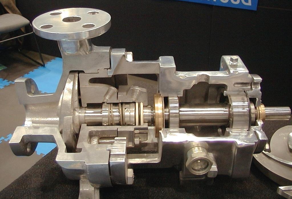
7

8 SEAL TYPE The mechanical seal shown in the pump photograph is a Type 1 mechanical seal. Probably the most widely recognized and also most common mechanical seal used in general service, low pressure applications. At Utex, we refer to this type as RS-1 The assembly shown in the pump is configured with a ceramic O-ring type stationary seat and is also equipped with a set screw collar.
9 SEALING THE LIQUID Mechanical seals were originally designed to lend a greater sealing capability than could be achieved using common packing. Before the advent of mechanical seals, pump users relied primarily on rope or braided style packing to achieve a seal around the shaft. A series of pieces or rings were installed into the pump stuffing box and they were compressed tightly so that they created a difficult leak path for the liquid to negotiate in order to leak to atmosphere.
10
11 SEALING THE LIQUID Early packing styles did not seal very well. In fact, until recently, braided packing styles required varying amounts of leakage for lubrication. If leakage was not permitted to occur, the packing would literally burn up and often cause severe damage to the pump shaft. Even with adequate leakage for lubrication, pump shaft wear was a commonly expected occurrence and as the shaft wore it would in turn, cause poor shaft packing life. As leakage becomes more excessive, the gland is tightened to reduce leakage.
12
13
14
15
16
17 SEALING THE LIQUID With the introduction of mechanical seals, this leakage could be controlled to a much greater degree. Let s look at the same pump with a mechanical seal installed. Note that the seal shown is an RS-1 with O- Ring type stationary and a set screw collar.
18
19
20 SEALING THE LIQUID You have probably taken notice of the illustration showing minor leakage to atmosphere. It is appropriate to point out at this time

21 LESSON NUMBER ONE ALL MECHANICAL SEALS LEAK.
22 SEALING THE LIQUID It is a fact, all mechanical seals leak. Like packing, the mechanical seal faces must also be lubricated. With proper application and design however, the leakage is so minute that actual droplets of liquid are not detected. Instead, the lubricating liquid will vaporize as it crosses the seal faces and the leakage is a gas or vapor. Since we are discussing the sealing of the liquid at the faces, let s take a look at the sealing points of a typical mechanical seal. Again, viewing the same pump and seal, note that there are four sealing points to consider.
23 The seal gland to the stuffing box Sealing on the shaft O.D. of the stationary And finally, the seal faces

24 BRIEF DISCUSSION ABOUT MECHANICAL SEAL FACE DYNAMICS
25 FACE FLATNESS The mechanical seal faces are obviously the most critical sealing point of a mechanical seal assembly. Although the faces can be manufactured from a myriad of different materials, one is typically carbon, while the other is usually a hard material. (i.e. Alox (Aluminum Oxide Ceramic), Tungsten Carbide, Silicon Carbide, etc.) In order for a seal to be achieved, the faces must be very flat. This is achieved by machining the faces, then lapping them to a fine finish. Flatness is measured in Light Bands. After lapping, the faces are placed on an Optical Flat, a clear glass surface where a monochromatic light is shined on the face. This single wavelength light will produce an image of rings or lines on the face. Each ring/line is One Light Band. Each light band is equivalent to or eleven millionths of an inch. This refers to the variations in the surface of the face. On most face materials, one light band is Utex s standard.

26 FACE FLATNESS This illustration shows a face being inspected on an Optical Flat. Take notice of the light bands that are visible on the reflection of the face. Laying a straight edge on a tangent to the inside circumference of the face, how many light bands are crossed?


27 Optically Flat Faces 100 psi Rotary Face Stationary Face 0 psi
28 FACE FLATNESS As was stated earlier, it is hoped that the application and design of the mechanical seal is suited for the service. If so, there is leakage of only vapor through the seal faces.

29 Pressure Drop & Vaporization Liquid 100 psi Liquid + Vapor Vapor + Liquid Vapor 0 psi 25 psi 50 psi
30 TYPES OF MECHANICAL SEALS
31 SEAL TYPES There are obviously many different types and configurations of mechanical seals. Shaft mounted and cartridge, balanced and unbalanced, pusher and nonpusher, single and multiple, etc., etc. Here we will examine the basic differences without going into a great detail.
32 SEAL TYPES First, let us examine shaft mounted vs. cartridge. A shaft mounted seal requires the pump user or assembler to actually install individual seal components into the equipment. Let s look at the installation of the RS-1 that we were looking at previously.
33 The stationary seat must be inserted into the seal gland.
34 The seal assembly is slipped onto the pump shaft and the set screws tightened in the correct position to insure proper installed length of the assembly.
35 The gland is tightened evenly so that the seal is compressed to it s recommended length.
36
37
38 SEAL TYPES A cartridge type mechanical seal is a pre-assembled package of seal components making installation much easier with fewer points for potential installation errors to occur. The assembly is pre-set so that no installed length calculations must be performed for determining where to set the seal. This pre-set is achieved by the use of set tabs that are removed once the seal is installed and the pump assembled.
39 Although the assembly may look a little menacing, it is basically no different than a shaft mounted arrangement as far as sealing components and sealing points are concerned. The same four sealing points exist here. Seal Gland Gasket Stationary O-ring Shaft/Sleeve O-ring One additional sealing point exists in this particular cartridge assembly. Have you found it? Seal Faces The set tabs are removed after installation.
40 SEAL TYPES Remember the number of steps involved in installing the shaft mounted seal. Now let s look at installing the cartridge seal that we just examined.
41
42
43
44 PUSHER VS. NON-PUSHER Both pusher and non-pusher types can be either shaft mounted or cartridge assemblies. The basic difference between pusher and non-pusher types have to do with the dynamics of the shaft packing or O-ring and whether or not it moves as the seal wears. As the seal faces wear down over time, they must be closed to compensate for lost face material. If the shaft O-ring must move when this compensation takes place, it is pushed forward by the components of the seal and by stuffing box pressure. If the seal is configured with a dynamic O-ring of this type the seal is called a pusher type.
45 Illustrated here is a Type RS-81, a common pusher seal. As the seal springs and other pressures in the stuffing box are exerted on the seal, closure of the faces is achieved. Rotating face and dynamic O-ring. Hard Stationary Face Closing forces exerted on the seal faces
46 As the softer carbon face wears down, the rotating face must move to maintain face closure.
47 Minute particles of carbon and solids from the process liquid that migrate across the seal faces build up on the shaft.
48 This build up will ultimately cause the seal to hang up and in most cases, failure will occur well before the seal is actually worn out.
49
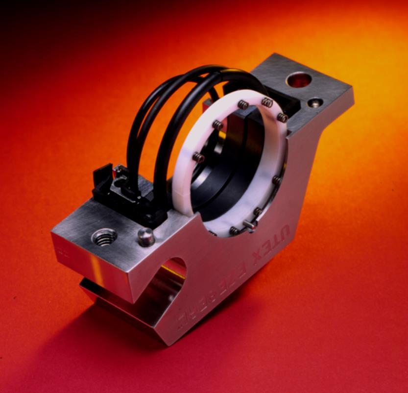
50 PUSHER VS. NON-PUSHER There are seal types that have no dynamic O-rings. All O- rings are static and the seal components compensate for face wear without pushing any sealing points. One of these types is called a Bellows Seal. The bellows can be constructed of metal, rubber or PTFE. The RS-1 seen earlier in this presentation is an Elastomer (or Rubber) Bellows Seal. Let s consider the metal variety.

51 METAL BELLOWS Metal bellows are constructed by welding leaflets into a series of convolutions. This series of convolutions is referred to as the Bellows Core. The photo shown here is a shaft mounted Utex-MB. Now take a look at how a bellows seal compensates for face wear.
52 Hard stationary face Carbon rotating face Metal bellows
53
54 The bellows core expands to compensate for face wear.
55
56 Debris can build up without causing hang up. This feature is probably the most notable selling point when comparing a bellows seal to a pusher type seal.
57 BALANCED VS. NON-BALANCED When speaking of Balance in reference to mechanical seals, we are not talking about Mechanical or Rotational Balance. Instead, we are referring to Hydraulic Balance. Since mechanical seals are subject to stuffing box pressure, this pressure is utilized to achieve and maintain seal face closure in a non-balanced seal. If stuffing box pressure is very high, typically over 100psi., then the closing force may be too great to allow the Boundary Layer Liquid that lubricates the faces to be sufficient and the faces will wear prematurely. A balanced seal compensates for higher pressures by locating the seal faces such that stuffing box pressure has less effect on face closure.
58 Balance Line Face OD Line Face ID Line A non-balanced seal has faces located outside the Balance Diameter of the seal. Stuffing box pressure is applied to the faces virtually evenly.
59 Balance Line Face OD Line Face ID Line The faces of a balanced seal are located so that a portion of the face contact occurs inside the balance diameter resulting in reduced closing force due to stuffing box pressure. This seal is a Type RS-8B1. (The B = balanced)
60 Balance Line Face ID Line Face OD Line Most metal bellows seals are balanced.
61 SINGLE VS. MULTIPLE Most rotating equipment is equipped with a single seal. This is what we have been examining thus far. Single shaft mounted seals, cartridges seals, balanced seals etc. Some applications call for a multiple seal configuration. These are typically dual seal arrangements but can also be a series of three or more. For our purposes we will examine dual seal arrangements since that really covers 99% of multiple seal applications.
62 DUAL SEALS Dual seals can be either pressurized or non-pressurized. This is in reference to the artificial environment that is provided to exist between the seals. A non-pressurized dual seal, also known as a Tandem arrangement, means that the inner, or primary seal is functioning as would a single seal. It is subject to stuffing box conditions, i.e. stuffing box pressure, process liquid to lubricate the faces and usually immersion of seal components in the process liquid. The secondary, or outside seal runs in a non-pressurized Buffer liquid that is supplied from an outside source, typically a nearby supply tank. In a non-pressurized dual arrangement, the outside seal is primarily there as a containment device in the event that the inside or primary seal is lost. A Back up or safety mechanism if you will. Let s look at a Dual Cartridge Seal.
63 Buffer fluid warmed by seal generated heat returns to the buffer supply tank Inside or Primary seal Outside or Secondary Seal Immersed in process liquid in the stuffing box Cool buffer fluid from the buffer supply tank enters via the inlet port
64 DUAL SEALS Since the outside or secondary seal runs in a non-pressurized clean lubricating liquid, it will generally last for an extended period of time. When the inside or primary seal fails, the leakage through the faces will be contained by the secondary seal until the pump can be shut down for seal replacement. Failure indication and shutdown devices can be attached to the buffer supply so that the pump operators know when the primary seal has failed.
65 DUAL SEALS When pumping volatile liquids, hazardous, corrosive, abrasive, etc. it is sometimes necessary to insure that the process liquid does not enter the atmosphere or the artificial environment created for the seal or even the seal faces. Pressurizing the artificial environment, 20 to 30 psi. above the pump stuffing box pressure will prevent process liquid from crossing the primary seal faces. Instead, boundary layer film liquid is supplied to the primary seal by the artificial environment or Barrier. The arrangement of seals can be the same as a non-pressurized in most cases. The difference is in how the seals perform. In a pressurized dual seal, the outboard or secondary has the tougher job of the two. It operates sealing high barrier pressure while the inboard or primary seal has clean lubricating liquid applied at differential pressure of only 20 to 30 psi. Now let s look at the environmental controls for operating dual seals.

66 Pressurized Dual Seal Artificial Environment Barrier System Non-Pressurized Dual Seal Artificial Environment Buffer System

67 SUCTION NON-PRESSURIZED BUFFER FLUID PLAN 52 / 7352 TO FLARE / RECOVERY SYSTEM DISCHARGE
68 PRESSURIZED GAS IN PRESSURIZED BARRIER FLUID PLAN 53 / 7353 DISCHARGE SUCTION
69 DUAL SEALS There are many more types of environmental control arrangements that are discussed in other programs. This presentation simply covers the basics. For more detailed information on this topic, contact your supervisor or a Sealing Technologies Representative.
70 SPLIT SEALS Some types of machinery are cumbersome to maintain. Large shafts, heavy components, and immovable drivers are some of these concerns. Often, a typical mechanical seal is impractical to use by the nature of it s installation requirements. In these cases it is frequently beneficial to use a Split Seal. In a Split Seal, all components are literally cut or split in half and they are assembled onto the equipment without removal or disassembly of the major equipment components. Obviously, these seals are prone to leak more readily than non-split seals so they are generally applied to processes where some leakage is acceptable. Even with some leakage, they will out perform common packing. Split Seals are often used on mixers, agitators and large volume, large shafted pumps.


71 UTEX EZ-SEAL The Utex EZ-Seal is split radially as shown in this photo. All internal components are also split and they are assembled onto the equipment shaft without removing the equipment from it s operating position or tearing down it s major components.

72 UTEX EZ-SEAL
73 SPLIT SEALS Aside from the fact that the components are split, split seals operate virtually the same way that most single cartridge or shaft mounted seals operate. By nature of their split design, their application is limited to lower pressures and non-volatile liquids. Now let s move onto our final discussion topic, Gas Buffer Seals.
74 GAS BUFFER SEALS The final seal type that we will look at during this course is the Gas Buffer Seal. Gas Buffer Seals are the latest advancement in sealing technology. There are as many different types as there are Sealing Product Manufacturers. They were designed to facilitate capabilities similar to a dual seal without requiring elaborate environmental controls or in the case of pressurized dual seals, without liquid contamination of the process liquid. We will briefly discuss the features of the Utex DCG Seal.

75 DUAL CO-AXIAL GAS SEAL The DCG Seal is a cartridge arrangement that contains a Gas Lift-Off Seal. In a Gas Lift-Off seal, the faces theoretically never contact. There is no fluid film between the faces and since they never contact, there is no need for it. A cut-away drawing of this seal will follow.
 that is inject into the seal gland port at 25 to 30 psi.")

76 DUAL CO-AXIAL GAS SEAL This control panel is used to adjust the gas flow (Nitrogen, Clean Plant Air, CO2, etc.) that is inject into the seal gland port at 25 to 30 psi. over stuffing box pressure. The gas flows through holes in the carbon stationary, separating the faces. As the seal operates, an envelope of gas surrounds the seal faces keeping process liquid out.


77 UTEX DUAL CO-AXIAL GAS Cut away view of the DCG shows the Stationary Carbon Face SEAL Rotating Face Gas inlet port Thumb not an integral part of the seal assembly
78 UTEX DUAL CO-AXIAL GAS SEAL Gas is supplied to the inlet port. The equipment can then be started and process suction opened allowing liquid into the stuffing box.
79 GAS BUFFER SEALS More detailed discussion of Gas Seals and their application is available.
80 PROGRAM SUMMARY Through this program we have looked at the basic principles and designs of mechanical seals. It is important to understand that detailed explanation of each topic discussed here is available. Hopefully this presentation has helped to improve your understanding of mechanical seals. Review this program again and as you have questions, comments or suggestions, ask your supervisor or a Sealing Technologies Representative. We want this training program to be as effective as possible and your input is valuable. Thanks, and enjoy working with mechanical seals.
81 UNDERSTANDING MECHANICAL SEALS PROGRAM END
UTEX INDUSTRIES, INC.
 UTEX INDUSTRIES, INC. C A R T R I D G E S E A L Externally located springs are virtually non-clogging Visible drive disc indicates face wear Setting clip removal unnecessary saving installation time Single-piece
Bulletin /06/2012 Supersedes 10/23/00. Installation of John Crane Type 73 Inflatable Mechanical Seal. Page 01 of 10
 01 of 10 1. Carefully read all instructions and notes before installation. 2. Bench Pre-assembly: a. Insert the support ring (item #1) inside the inflatable boot (item #2) to form inflatable seal assembly
Installation Instructions
 Installation Instructions TM Five Star Seal 80 Series Dual, Cartridge Mounted, Flexible Stator Pusher Seal Designed for General Service Applications 86 and 87 Experience In Motion Description The 86/87
TYPE ECS SEAL METAL BELLOWS DRY-RUNNING SECONDARY CONTAINMENT Technical Specification
 Low Temperature Design A Spacer Ring B Compression Ring C Retaining Ring D Wave Spring E O-ring F ent/drain Connection G Seat/Mating Ring H Insert I Bellows Assembly J Housing A K Spacer B F G H I C D
4400 TwinHybrid Gas Seal
 4400 TwinHybrid Gas Seal EQUIPMENT PREPARATION MECHANICAL SEAL INSTALLATION INSTRUCTIONS 1 2 200.005" 0,13 mm 125 µ" 3,2 µm R a 3 4 32 µ" 0,8 µm R a 1000 ±.002" 0,05mm CAUTIONS These instructions are general
Installation Instructions
 Installation Instructions BW Seals Uniseal Series Cartridge metal bellows single and dual seals Experience In Motion Description The Uniseal metal bellows seal series consists of: Uniseal I - Single seals
Compressor Seal Replacement and Upgrades SERVICES
 Compressor Seal Replacement and Upgrades SERVICES Compressor Seal Upgrades An Elliott Group compressor seal upgrade increases seal reliability and reduces process gas leakage to improve overall efficiency.
Installation Instructions
 Durametallic SL-5000 and SL-5200 Seals Cartridge Slurry Seals Installation Instructions Experience In Motion SL-5000 and SL-5200 Cartridge Seals are complete preset seal assemblies which include the sleeve
KAYDON RING & SEAL, INC.
 KAYDON RING & SEAL, INC. K-DGS Series Dry Gas Seals KAYDON K-DGS Dry Gas Seals K-DGS Configurations Single Seal (K-DGS) Compact and economical, the single seal configuration is recommended for non-toxic
Produc. Atmosph. here
 Mechanical Seal Selection API 682 (2 nd Edition) Table Of Contents: 1) Seal Selection Methods 2) Fundamentals Of Sealing 3) Introduction To API 682 (2 nd Edition) 4) Several Important Terms That Used In
TURBINE SEAL: AXIAL TYPE DESIGN
 TURBINE SEAL: AXIAL TYPE DESIGN Our axial type seals are specifically designed for application to hydroelectric turbines and large water pumps for sewage handling, filtration, irrigation, and more. Our
Берг АБ Тел. (495) , факс (495) Turning Ideas Into Engineered Solutions KAYDON RING & SEAL, INC.
 , факс (495) Turning Ideas Into Engineered Solutions KAYDON RING & SEAL, INC.") Turning Ideas Into Engineered Solutions RING & SEAL, INC. K-CBS Series Circumferential Barrier Seals Kaydon s high performance circumferential barrier seals back up DGS systems with performance & economy.
Turning Ideas Into Engineered Solutions RING & SEAL, INC. K-CBS Series Circumferential Barrier Seals Kaydon s high performance circumferential barrier seals back up DGS systems with performance & economy.
John Crane Type 609HTC/ECS (High-Temperature Corrosion Resistant) Sealol Metal Bellows Seal Installation Instructions
 Sealol Metal Bellows Seal Installation Instructions") I-609HTC/ECS John Crane Type 609HTC/ECS (High-Temperature Corrosion Resistant) Sealol Metal ellows Seal Installation Instructions Foreword These instructions are provided to familiarize the user with the
I-609HTC/ECS John Crane Type 609HTC/ECS (High-Temperature Corrosion Resistant) Sealol Metal ellows Seal Installation Instructions Foreword These instructions are provided to familiarize the user with the
Application of Double Vs Tandem Dry gas seal Advantages.
 Application of Double Vs Tandem Dry gas seal Advantages. John Sears WW Director, Compressor Products. Flowserve Corporation. Unit #2207, 220 Fisher Street, SE, Calgary, Alberta, T2H 2H8 Canada; World Wide
Premature Dry Gas Seal Failure on a Sales Gas Centrifugal Compressor. Sergio Vidal (Saudi Aramco, Hawiyah Gas Plant - Reliability Unit)
") Premature Dry Gas Seal Failure on a Sales Gas Centrifugal Compressor Sergio Vidal (Saudi Aramco, Hawiyah Gas Plant - Reliability Unit) 1 Index Copyright Saudi Aramco (YEAR). All rights reserved. No portion
Premature Dry Gas Seal Failure on a Sales Gas Centrifugal Compressor Sergio Vidal (Saudi Aramco, Hawiyah Gas Plant - Reliability Unit) 1 Index Copyright Saudi Aramco (YEAR). All rights reserved. No portion
Dean Pump Self-Priming Chemical Process Pumps
 Bulletin C 1.2.34.7 Dean Pump Self-Priming Chemical Process Pumps php Series HEAD CAPACITY RANGE CHARTS php Self Primer - 2 Pole 3500 RPM 500 CAPACITY M 3 /HR 2900 RPM 50 HERTZ 25 50 75 125 150 400 TOTAL
INSTALLATION, OPERATION & MAINTENANCE GUIDE
 INSTALLATION, OPERATION & MAINTENANCE GUIDE INTERNATIONAL BRAZIL SOUTHERN USA HEADQUARTERS REPAIR & SERVICE 1 Jackson Street Rua Javaés, 441/443 1719 South Sonny Avenue Essex Junction, VT 05452 Bom Retiro,
Air Operated Hydraulic Pumping Systems to 50,000 psi
 High Pressure Equipment Air Operated Hydraulic Pumping Systems to 50,000 psi PS-10: 10,000 psi PS-20: 20,000 psi PS-30: 30,000 psi PS-40: 40,000 psi PS-50: 50,000 psi PS-90: 90,000 psi High Pressure air
ROTATING DISK VALVES INSTALLATION AND MAINTENANCE 1. SCOPE 3 2. INFORMATION ON USAGE 3 3. VALVE TYPES 3 4. OPERATORS 5 5. VALVE CONSTRUCTION 6
 Sub Section INDEX Page Number 1. SCOPE 3 2. INFORMATION ON USAGE 3 3. VALVE TYPES 3 4. OPERATORS 5 5. VALVE CONSTRUCTION 6 6. INSTALLATION AND OPERATION 6 7. MAINTENANCE 8 8. REPAIR 9 9. ASSEMBLY 10 10.
Installation Instructions
 Installation Instructions Durametallic SLM-6000, SLM-6100 Self contained cartridge medium duty slurry seal Experience In Motion 1 Cartridge Installation Instructions The following instruction manual is
MU102: Mechanical Seals Applications for Rotating Machinery
 MU102: Mechanical Seals Applications for Rotating Machinery MU102 Rev.001 CMCT COURSE OUTLINE Page 1 of 5 Training Description: All Rotating Equipment Machinery require controlling of the pumped fluids
TYPE 3710 CARTRIDGE SPLIT SEAL Technical Specification
 A Mating Ring B Mating Ring/ Retaining Ring C Mating Ring/ Clamp Ring D Mating Ring Adapter E Primary Ring F Primary Ring/ Retaining Ring G Finger Springs H Spring Retainer I Gland O-ring J Flat Gasket
Design Enhancements on Dry Gas Seals for Screw Compressor Applications
 VDI-Berichte Nr. 1932, 2006 B 8 331 Design Enhancements on Dry Gas Seals for Screw Compressor Applications Dipl.-Ing C. Kirchner, Flowserve Dortmund GmbH & Co KG, Dortmund Introduction The development
INSTALLATION, OPERATION AND MAINTENANCE MANUAL
 3200-300 INSTALLATION, OPERATION AND MAINTENANCE MANUAL PLEASE READ CAREFULLY YOUR WARRANTY MAY BE VOID IF INSTRUCTIONS ARE NOT FOLLOWED Note: when ordering parts give pump model and serial number Cornell
Goulds 3296 EZMAG. Chemical Process Pump
 Goulds 3296 EZMAG Chemical Process Pump 3296 EZMAG Chemical Process Pump Capacities to 700 gpm (160 m3/h) Heads to 620 ft (189 m) Temperatures to 535 F (280 C) Pressures to 275 PSIG Performance Features
PROCESS ROTATING EQUIPMENT (CENTRIFUGAL PUMPS )
") PROCESS ROTATING EQUIPMENT ( ) Slide No: ١ Pumps can be divided into two main groups: Displacement pumps Dynamic pumps Slide No: ٢ Slide No: ٣ Slide No: ٤ Slide No: ٥ BASIC CENTRIFUGAL PUMP PARTS Casing
PROCESS ROTATING EQUIPMENT ( ) Slide No: ١ Pumps can be divided into two main groups: Displacement pumps Dynamic pumps Slide No: ٢ Slide No: ٣ Slide No: ٤ Slide No: ٥ BASIC CENTRIFUGAL PUMP PARTS Casing
Installation Instructions
 Installation Instructions ISC Series Innovative Standard Cartridge seal designed for ANSI and general purpose applications with maximum interchangeability between designs. Experience In Motion Description
Figure 1: Hydrostatic Pressure Forces Are Perpendicular to the Surface
 Pressure Hulls and Canisters 2 Cornerstone Electronics Technology and Robotics III (Notes primarily from Underwater Robotics Science Design and Fabrication, an excellent book for the design, fabrication,
SABERINDO PACIF SABERINDO PACIFIC CIFIC SABERINDO PA. A Tyco International Company
 CIF A Tyco International Company 1 Foam Concentrate CIF 3% AFFF -UL Listed -UL Canada Listed 6% AFFF 6 parts AFFF concentrate to 94 parts water -UL Listed- Foam Liquid -UL Canada Listed 3% FLUOROPROTEIN
Installation Instructions
 Installation Instructions Durametallic MD-200 Series Gas Dual Cartridge Canister Seal for Mixers and Agitators Experience In Motion 1 Equipment Check 1.1 Follow plant safety regulations prior to equipment
TYPE 7828G/7828GD 7800 SERIES UNIVERSAL VESSEL SEAL Technical Specification
 A Face/Primary Ring B Seat/Mating Ring C O-Ring D Disc E Sleeve F Retaining Sleeve G Retaining Clip G D C E F C A B Patent numbers: 5,938,206 and 6,142,478 Product Description The universal vessel seal
INSTALLATION, MAINTENANCE & OPERATING INSTRUCTIONS 2-4 REDUCED PORT/ FULL PORT (5700/6700) ANSI CLASS 150/300/600/900/1500/2500 TRUNNION BALL VALVES
 ANSI CLASS 150/300/600/900/1500/2500 TRUNNION BALL VALVES") PBV-USA,Inc. 12735 Dairy Ashford. Stafford, Texas USA 77477 281-340-5400; 800-256-6193 FAX: 281-340-5499 INDUSTRIAL BALL VALVES IM0 69 April 2001 Rev 9 INSTALLATION, MAINTENANCE & OPERATING INSTRUCTIONS
PBV-USA,Inc. 12735 Dairy Ashford. Stafford, Texas USA 77477 281-340-5400; 800-256-6193 FAX: 281-340-5499 INDUSTRIAL BALL VALVES IM0 69 April 2001 Rev 9 INSTALLATION, MAINTENANCE & OPERATING INSTRUCTIONS
Design. Pompetravaini-NSB API SB Liquid Ring Compressor for Gas Processing. Working Principle
 SB Pompetravaini-NSB API SB Liquid Ring Compressor for Gas Processing A family of API liquid ring compressors has been developed and has been in the market for nearly a decade, they are specifically made
Installation, Operation and Maintenance Manual for Back Pressure Regulator
 Installation, Operation and Maintenance Manual for Back Pressure Regulator Model 8860 2009 Groth Corporation IOM-8860 Rev. B 12541 Ref. ID: 95565 Page 2 of 13 Table of Contents I. INTRODUCTION 3 II. DESIGN
API Piping Plan 62: A Reliable Quench System
 MAY05PUMPS&SYSp24-33 4/19/05 4:04 PM Page 24 It s one of the few methods you have to control the environment outside a mechanical seal. By Keith Schindler, PE, Schindler Engineering, Inc., and Paul McMahan,
Tradition & Technology
 Gaterotor Support Gaterotor Single Screw Compressors Design & Operation Bearing Bearings Main Screw Parallex Slide System The VSM Single Screw Compressor has one main rotor and two gaterotors. All bearings
Models: C62/63/64-A/D
 Installation & Service C62-991-24A3 Models: C62/63/64-A/D Diaphragm Bypass Pressure Regulating Valves IMPORTANT Record your pump model number and serial number here for easy reference: Model No. Serial
Installation Instructions For Flat Seated Bolted Type RAH Series Disk Holders
 Installation Instructions For Flat Seated Bolted Type RAH Series Disk Holders RA Series Rupture Disks 1. WARNING a) Read the complete instructions before attempting to install the rupture disk and holder
TYPE 7800 SERIES 7848D/7848W UNIVERSAL VESSEL SEAL Technical Specification
 A Face/Primary Ring B Seat/Mating Ring C O-ring D Disc E Sleeve F Retaining Sleeve D C E C F A B Product Description The Universal Vessel Seal 7800 Series is a modular cartridge seal for use in a wide
4400H TwinHybrid Gas Seal
 INSTALLATION, OPERATION and REUILD INSTRUCTIONS 4400H TwinHybrid Gas Seal Installation, Operation and Rebuild Instructions TALE OF CONTENTS 1.0 Cautions... 2 2.0 Transport and Storage... 2 3.0 Description...
MODEL 200 KNIFE GATE VALVES INSTALLATION & MAINTENANCE MANUAL
 MODEL 200 KNIFE GATE VALVES INSTALLATION & MAINTENANCE MANUAL Index 1. List of components / General arrangement 2. Description 3. Handling 4. Installation 5. Actuators / Operation 6. Maintenance a. Changing
TYPE 2800E EXTERNALLY MOUNTED, GAS LUBRICATED, NON-CONTACTING, DOUBLE CARTRIDGE SEAL
 A Seat/Mating Ring B Face/Primary Ring (inboard) C Spring D Face/Primary Ring (outboard) E O-Ring F Drive Collar G Setting Ring H Sleeve TYPE 2800E B A D C H E Spiral Groove Technology G F Product Description
INDUSTRIAL VALVES MODELS: C62-A; C62-D. INSTRUCTION MANUAL Installation Operation Parts Service DIAPHRAGM BYPASS PRESSURE REGULATING VALVES
 INSTRUCTION MANUAL Installation Operation Parts Service IMPORTANT Record your Regulator model number and serial number here for easy reference: Model No. Serial No. Date of Purchase When ordering parts
SEPARATION SEAL UPGRADE TO OVERCOME REPETITIVE FAILURES
 SEPARATION SEAL UPGRADE TO OVERCOME REPETITIVE FAILURES Author : Rasgas Pradip B Sonavane (Senior Engineer - Rotating Equipment) AbdelKhalek, Mohamed H (Advisor - Rotating Equipment) Quraisy Shatri (Head
Installation Instructions
 Installation Instructions High Temperature Metal Bellows Seals Cartridge seals with flexible graphite gaskets BXH, BXHH, BXRH, BRC, GTSP, GSDH Series 1 Equipment Check 1.1 Follow plant safety regulations
GAS SEAL CONTAMINATION
 Proceedings of the First Middle East Turbomachinery Symposium February 13-16, 2011, Doha, Qatar GAS SEAL CONTAMINATION Raphael Bridon Components Focus Factory Manager Dresser-Rand Le Havre, France rbridon@dresser-rand.com
Crosby style JCE Safety Valve Installation, Maintenance and Adjustment Instructions CROSBY
 CROSBY Table of contents 1. Installation 1 1.1. Drainage 1 1.2. Discharge pipework 1 1.3. Preparation for installation 1 2. Pressure adjustment 1 3. Maintenance 1 4. Dismantling 1 4.1. All valve types
Repair Alert Never use compressed air to dismantle a hydraulic cylinder
 Repair Alert Never use compressed air to dismantle a hydraulic cylinder Topic: A hydraulic cylinder with integral pilot-operated check valve can present a considerable safety hazard for an unsuspecting
Improve Reliability of Turbomachinery Lubrication and Sealing Systems
 Improve Reliability of Turbomachinery Lubrication and Sealing Systems Fisher Pressure Control Solutions For Turbomachinery Applications Protect the integrity of your Turbomachinery support system Turbomachinery
Unit 24: Applications of Pneumatics and Hydraulics
 Unit 24: Applications of Pneumatics and Hydraulics Unit code: J/601/1496 QCF level: 4 Credit value: 15 OUTCOME 2 TUTORIAL 9 ACCUMULATORS The material needed for outcome 2 is very extensive so there are
BUTTERFLY VALVES Series 800
 BUTTERFLY VALVES Series 800 WARNING Before proceeding read ALL instructions and become familiar with the equipment and associated drawings. Follow ALL applicable safety regulations and codes for pressurized
Hot Tapping Machine. OPERATIONS MANUAL and OPERATING INSTRUCTIONS
 262-2040 Hot Tapping Machine For performing 1/4 6 Hot taps 285 psi or less. Municipal Water, Sewage, & Building Services Use OPERATIONS MANUAL and OPERATING INSTRUCTIONS WARNING: These instructions are
Wafer Check Valve. Contents. User s Manual. (1) Be sure to read the following description of our product warranty 1
 Be sure to read the following description of our product warranty 1") Serial No. H-V066-E-3 Wafer Check Valve User s Manual Contents (1) Be sure to read the following description of our product warranty 1 (2) General operating instructions 2 (3) General instructions for
Serial No. H-V066-E-3 Wafer Check Valve User s Manual Contents (1) Be sure to read the following description of our product warranty 1 (2) General operating instructions 2 (3) General instructions for
FLUID POWER FLUID POWER EQUIPMENT TUTORIAL ACCUMULATORS. This work covers part of outcome 2 of the Edexcel standard module:
 FLUID POWER FLUID POWER EQUIPMENT TUTORIAL ACCUMULATORS This work covers part of outcome 2 of the Edexcel standard module: UNIT 21746P APPLIED PNEUMATICS AND HYDRAULICS The material needed for outcome
double rotary environmental cartridge mechanical seals 302 TM series
 double rotary environmental cartridge mechanical seals 302 TM series first4seals plc, mount street, bradford, west yorkshire. bd3 9sn united kingdom Tel: +44 (0) 1274 720775 Fax: +44 (0) 1274 729022 email:
APP pumps APP and APP Disassembling and assembling
 Service guide APP pumps APP 11-13 and APP 16-22 Disassembling and assembling hpp.danfoss.com Table of Contents Contents 1. Introduction... 2 2. Disassembling the pump... 3 3. Assembling the pump... 6 4.
Crusher Bearings: Knowing the Basics Leads to Better Care
 Technical Article by Brian Berg and Fabiana Maggico, Manager - Upstream Marketing at The Timken Company Table of Contents: Compression Crushers 2 Jaw Crushers 2 Cone Crushers 2 Impact Crushers 3 Better
Inflatable Packer Single & Double. Single & Double Packer Dimension. Wireline Packer. Water Testing Packer (WTP) Packer
 Packer") Inflatable Packer Single & Double Single & Double Packer Dimension Wireline Packer Water Testing Packer (WTP) Packer Packer Working Pressure & Depth Chart Packer Water Hand Pump Packer Air Driven Pump
Inflatable Packer Single & Double Single & Double Packer Dimension Wireline Packer Water Testing Packer (WTP) Packer Packer Working Pressure & Depth Chart Packer Water Hand Pump Packer Air Driven Pump
Leak testing of Valves. Standards for acceptable Rates of Valve Leakage
 Leak testing of Valves Standards for acceptable Rates of Valve Leakage American Petroleum Institute (API) The API standard 598: Valve Inspection and Testing, covers the testing and inspection requirements
5k Slickline Lightweight Pressure Control Equipment 4 ID
 5k Slickline Lightweight Pressure Control Equipment 4 ID Table of Contents 5k Slickline Lightweight Pressure Control Equipment 4 ID... 1 Hydraulic Slickline Stuffing Box... 3 Wireline Lubricators... 4
Disassembling and assembling APP and APP 16-22
 MAKING MODERN LIVING POSSIBLE Instruction Disassembling and assembling APP 11-13 and APP 16-22 ro-solutions.com Table of Contents 1. Disassembling...3 2. Disassembling the pump...3 3. Assembling the pump....7
Revision 2013 Vacuum Technology 1-3 day Good Vacuum Practice 1 Day Course Outline
 Revision 2013 Vacuum Technology 1-3 day Good Vacuum Practice 1 Day Course Outline This training course outline is intended to cover the following: Introduction to vacuum Measurement Lubricated rotary pumps
Proper Pump Installation Practices
 Proper Pump Installation Practices 80-779, Rev. 10/08 There is a Reason Every Unit Comes With This Bright Orange Tag! Proper Alignment and Coupling Installation Do Not Drive Coupling Onto Shaft Pump Alignment
The Discussion of this exercise covers the following points: Pumps Basic operation of a liquid pump Types of liquid pumps The centrifugal pump.
 Exercise 2-3 Centrifugal Pumps EXERCISE OBJECTIVE In this exercise, you will become familiar with the operation of a centrifugal pump and read its performance chart. You will also observe the effect that
Simplicity in VRU by using a Beam Gas Compressor
 Simplicity in VRU by using a Beam Gas Compressor By Charlie D. McCoy and Mark Lancaster Abstract: Vapor Recovery Units are often expensive, complicated to operate and unable to deal with High H2S and liquids.
Improved Mean Time Between Planned Maintenance (MTBPM) for Mechanical Seals in Process Pumps
 for Mechanical Seals in Process Pumps") Flow Solutions Division Improved Mean Time Between Planned Maintenance (MTBPM) for Mechanical Seals in Process Pumps Seal Chamber Design Introduction Attention is being focused on the need to increase
Flow Solutions Division Improved Mean Time Between Planned Maintenance (MTBPM) for Mechanical Seals in Process Pumps Seal Chamber Design Introduction Attention is being focused on the need to increase
sealing TECHNOLOGY AW Chesterton Co is introducing API 682 mechanical seals are versatile and provide emissions sealing Contents
 sealing TECHNOLOGY ISSN 1350-4789 October 2010 API 682 mechanical seals are versatile and provide emissions sealing AW Chesterton Co is introducing a new line of API 682 mechanical seals and systems for
Development of a High Pressure, Oil Free, Rolling Piston Compressor
 Purdue University Purdue e-pubs International Compressor Engineering Conference School of Mechanical Engineering 1994 Development of a High Pressure, Oil Free, Rolling Piston Compressor S. J. Delmotte
Contents. Stainless Steel Side Block. 1.1 Separating the Side Block. Stainless Steel Side Block Reassembly of. Assembly from the Helmet Shell
 Separating the Side Block Assembly from the Helmet Shell Contents SSB-1 SSB-3 SSB-5 SSB-5 SSB-7 1.1 Separating the Side Block Assembly from the Helmet Shell 1.2 Side Block Assembly Replacement 1.3 Defogger
Manual Actuated Boiler Blowdown Valves
 Manual Actuated Boiler Blowdown Valves Installation and Maintenance Instructions 1. Safety information 2. General product information 3. Installation 4. Operation 5. Maintenance 6. Spare parts p.1 1. Safety
VRS Assembly & Operating Instructions
 VRS Assembly & Operating Instructions Models VRS-18 Pn #270003 VRS-24 Pn #270006 VRS-30 Pn #270010 Not for use on pressure vessels equipped with Automatic exhaust valve (680 controls) EMPIRE ABRASIVE EQUIPMENT
Packer-Type Gas Separator with Seating Nipple
 8 th Annual Sucker Rod Pumping Workshop Renaissance Hotel Oklahoma City, Oklahoma September 25-28, 2012 Packer-Type Gas Separator with Seating Nipple Jim McCoy Lynn Rowlan, Dieter Becker, Ken Skinner -
THE HF-300 SERIES. Operating and Service Manual. Series includes all variants of HF-300/301
 THE HF-300 SERIES Operating and Service Manual Series includes all variants of HF-300/301 Issue A July 2015 1 TABLE OF CONTENTS 1. Description... 3 2. Installation... 3 3. Operation... 4 3.1. Spring Loaded...
OPERATING INSTRUCTIONS
 OPERATING INSTRUCTIONS Tempe Pressure Cell June 1995 Fig. 1a 1400 Tempe Pressure Cells with 3cm cylinders and 6cm cylinders) mounted on the Tempe Cell Stand Fig. 1b Disassembled 1400 Tempe Pressure Cell
Pump Selection and Sizing (ENGINEERING DESIGN GUIDELINE)
") Guidelines for Processing Plant Page : 1 of 64 Feb 2007 (ENGINEERING DESIGN GUIDELINE) Author: A L Ling Checked by: Karl Kolmetz TABLE OF CONTENT INTRODUCTION Scope 5 General Design Consideration Type
Guidelines for Processing Plant Page : 1 of 64 Feb 2007 (ENGINEERING DESIGN GUIDELINE) Author: A L Ling Checked by: Karl Kolmetz TABLE OF CONTENT INTRODUCTION Scope 5 General Design Consideration Type
Model 7989T Steel Pipe Squeezer Sch. 40 & Sch. 80. Operations Manual
 10-12 Steel Pipe Squeezer Sch. 40 & Sch. 80 Operations Manual 1.0 Introduction This manual is issued as a basic operation manual covering the Regent Model 7989T, Pipe Squeezer and Pump as manufactured
Operation and Maintenance Instructions
 Hydratight Limited Bentley Road South Darlaston West Midlands WS10 8LQ United Kingdom Tel: +44 121 50 50 600 Fax: +44 121 50 50 800 E-mail: enquiry@hydratight.com Website: www.hydratight.com TOP COLLAR
MECHANICAL EQUIPMENTS: COMPRESSORS, PUMPS, SEALS, SPEED DRIVES, CONTROL VALVES & ACTUATORS & SAFETY RELIEF VALVES
 Training Title MECHANICAL EQUIPMENTS: COMPRESSORS, PUMPS, SEALS, SPEED DRIVES, CONTROL VALVES & ACTUATORS & SAFETY RELIEF VALVES Training Duration 5 days Training Venue and Dates REF Mechanical Equipments:
Offshore Equipment. Yutaek Seo
 Offshore Equipment Yutaek Seo Flash Gas Compressor (East spar) Dehydration NGL recovery Slug catcher Separator Stabilization Booster compressor Gas export compression (Donghae-1 Platform) May 7 th Gas
TECHNICAL DATA. Q = C v P S
 January 6, 2012 Preaction 348a 1. Description Viking supervised Surefire Preaction Systems utilize the Viking G-6000P Valve. The small profile, lightweight, pilot operated Viking G-6000P Valve comes complete
Mechanical Seal Piping Plans
 Mechanical Seal Piping Plans Companion Booklet Single Seals Dual Seals Quench Seals Second. Cont. Dual Gas Introduction A primary factor in achieving highly reliable, effective sealing performance is to
TECHNICAL DATA. Q = C v P S
 January 6, 2012 Preaction 333a 1. Description Viking supervised Surefire Preaction Systems Utilize the Viking G-3000P Valve. The small profile, lightweight, pilot-operated Viking G-3000P Valve comes complete
Circulation Systems for Single and Multiple Seal Arrangements
 Circulation Systems for Single and Multiple Seal Arrangements Gordon Buck and Ralph Gabriel, John Crane This discussion opens a three-part series covering mechanical seal piping plans that provide guidelines
Needle valve. Contents. User s Manual. (1) Be sure to read the following warranty clauses of our product 1. (2) General operating instructions 2
 Be sure to read the following warranty clauses of our product 1. (2) General operating instructions 2") Serial No. H-V024-E-7 Needle valve User s Manual Contents (1) Be sure to read the following warranty clauses of our product 1 (2) General operating instructions 2 (3) General instructions for transportation,
Serial No. H-V024-E-7 Needle valve User s Manual Contents (1) Be sure to read the following warranty clauses of our product 1 (2) General operating instructions 2 (3) General instructions for transportation,
THE BP-690 SERIES. Operating and Service Manual. Series includes all variants of BP-LF/MF-690/691
 THE BP-690 SERIES Operating and Service Manual Series includes all variants of BP-LF/MF-690/691 Issue B April 2015 1 TABLE OF CONTENTS 1. Description... 3 2. Installation... 3 3. Operation... 4 4. Special
Operation Manual Piston Sensed Gas Pressure Regulators
 687 Technology Way Napa, CA 94558 Phone: (707) 259-0102 FAX: (707) 259-0117 www.aptech-online.com Operation Manual Piston Sensed Gas Pressure Regulators (Models KT9, KT10, Welded KT10, KT12) Table of Contents:
DEVICES FOR FIELD DETERMINATION OF WATER VAPOR IN NATURAL GAS Betsy Murphy MNM Enterprises 801 N. Riverside Drive Fort Worth, Texas 76111
 INTRODUCTION Water vapor in natural gas has more than a substantial effect on the quality of the gas stream. Without quality measurement of water vapor the gas is basically not saleable. Contracts are
KTM OM-2 SPLIT BODY FLOATING BALL VALVES INSTALLATION AND MAINTENANCE INSTRUCTIONS
 Before installation these instructions must be fully read and understood SECTION 1 - STORAGE 1.1 Preparation and preservation for storage All valves should be properly packed in order to protect the parts
TECHNICAL DATA. Q = C v P S
 January 6, 2012 Preaction 331a 1. Description Viking supervised Double-Interlocked Electric/Pneumatic Release Preaction Systems utilize the Viking G-3000P Valve. The small profile, lightweight, pilot-operated
TECHNICAL DATA. Q = C v P S
 Preaction 346a 1. Description The 6 Model G-6000P Electric Release Preaction System Riser Assembly can be used as a Single Interlock Preaction System with Electric Release, or as a Double Interlock Preaction
Case Study: Root Cause on Seal Failure in Refinery. Case A: Even a standby pump can have a seal failure, and a hazard associated with it
 Case Study: Root Cause on Seal Failure in Refinery By Sourav Kumar Chatterjee Sr. Manager Reliability Improvement HPCL Mumbai Refinery Mumbai, India Many different factors contribute towards the failure
PDY TON HYDRAULIC CRIMPING TOOL WARNING
 OPERATORS ORS GUIDE PDY-1220 12 TON HYDRAULIC CRIMPING TOOL All information found in this guide must be read and understood before use or testing of this tool. Failure to read and understand these warnings
// ADapters GUIDelines
 // ADapters GUIDelines ADAPTER SELECTION Selection of an appropriate ALFAGOMMA adapter for a given application depends on the fluid system operating parameters listed below and the tube material and wall
INSTALLATION & MAINTENANCE INSTRUCTION
 ARCHON Industries, Inc Liquid Level Gauges Models: BT-LLG ND-LLG INSTALLATION & MAINTENANCE INSTRUCTION Instruction No.: 1014.2 Revision Issued: 3/01/03 Approved: Engineering Manager Warning ONLY QUALIFIED
FIELD TROUBLESHOOTING COMMON MECHANICAL SEAL PIPING PLANS. Michael Huebner Principal Engineer Flowserve Corporation Pasadena, TX USA
 FIELD TROUBLESHOOTING COMMON MECHANICAL SEAL PIPING PLANS Michael Huebner Principal Engineer Flowserve Corporation Pasadena, TX USA Ronald Hurst Manager, Application Engineering Flowserve Corporation Pasadena,
ANNEX AMENDMENTS TO THE INTERNATIONAL CODE FOR FIRE SAFETY SYSTEMS (FSS CODE) CHAPTER 15 INERT GAS SYSTEMS
 CHAPTER 15 INERT GAS SYSTEMS") Annex 3, page 2 ANNEX AMENDMENTS TO THE INTERNATIONAL CODE FOR FIRE SAFETY SYSTEMS (FSS CODE) CHAPTER 15 INERT GAS SYSTEMS The text of existing chapter 15 is replaced by the following: "1 Application This
Annex 3, page 2 ANNEX AMENDMENTS TO THE INTERNATIONAL CODE FOR FIRE SAFETY SYSTEMS (FSS CODE) CHAPTER 15 INERT GAS SYSTEMS The text of existing chapter 15 is replaced by the following: "1 Application This
ADVANCEMENTS IN MECHANICAL SEALING - API 682 FOURTH EDITION. Gordon S. Buck John Crane Inc. Baton Rouge, LA, USA
 ADVANCEMENTS IN MECHANICAL SEALING - API 682 FOURTH EDITION Michael B. Huebner Flowserve Corporation Deer Park, TX, USA Gordon S. Buck John Crane Inc. Baton Rouge, LA, USA Henri V. Azibert A.W. Chesterton
CARTRIDGE FILTERS TECHNICAL MANUAL MT 080. Installation, commissioning and maintenance instructions. 08/02 Edition
 CARTRIDGE FILTERS TECHNICAL MANUAL MT 080 Installation, commissioning and maintenance instructions 08/02 Edition 1 2 CONTENTS 1.0 PAGE INTRODUCTION 1.1 MAIN FEATURES 1.2 OPERATION 1.3 CLOSING OF HEAD WITH
COMBINATION AIR RELEASE DEGASSING (CARD) VALVES INSTALLATION AND MAINTENANCE MANUAL
 VALVES INSTALLATION AND MAINTENANCE MANUAL") COMBINATION AIR RELEASE DEGASSING (CARD) VALVES INSTALLATION AND MAINTENANCE MANUAL SPECIFICATIONS: The CARD series air valves are available in 3 pipe sizes, 1, 2 and 4 NPT or socket. Maximum inlet pressure
COMBINATION AIR RELEASE DEGASSING (CARD) VALVES INSTALLATION AND MAINTENANCE MANUAL SPECIFICATIONS: The CARD series air valves are available in 3 pipe sizes, 1, 2 and 4 NPT or socket. Maximum inlet pressure
TECHNICAL DATA. Q = C v P S
 January 6, 2012 Preaction 347a 1. Description Viking supervised Double-Interlocked Electric/Pneumatic Release Preaction Systems utilize the Viking G-6000P Valve. The small profile, lightweight, pilot operated