APPLYING VARIABLE SPEED PRESSURE LIMITING CONTROL DRIVER FIRE PUMPS. SEC Project No
|
|
|
- Winfred McCarthy
- 6 years ago
- Views:
Transcription

1 APPLYING VARIABLE SPEED PRESSURE LIMITING CONTROL DRIVER FIRE PUMPS SEC Project No November 20, 2006
2 TABLE OF CONTENTS I. ABSTRACT...1 II. INTRODUCTION...1 III. HISTORY...2 IV. VARIABLE SPEED PRESSURE LIMITING CONTROL PUMP CHARACTERISTICS...3 V. DESIGN CONSIDERATIONS...5 VI. DESIGN FOR HIGH RISE...6 VII. DESIGN FOR ESFR AND FLUCTUATING WATER SUPPLIES...10 VIII. CONCLUSIONS...12 IX. REFERENCED DOCUMENTS...13 SEC Project No i- November 20, 2006
3 APPLYING PRESSURE LIMITING PUMPS TO FIRE PROTECTION APPLICATIONS I. ABSTRACT Variable Speed pressure limiting control driven fire pumps are now permitted by the 2003 edition of NFPA 20. This article discusses the characteristics of these pumps, and the practical application of these pumps in high rise, and ESFR applications. II. INTRODUCTION Variable Speed pressure limiting control drivers were added to the 2003 edition of NFPA 20, Standard for the Installation of Stationary Pumps for Fire Protection. This article discusses the practical application in high rise and ESFR systems. The following terms will be used in this article. Net pump pressure: Net churn pressure Net operating pressure or Net rated pressure: Operating pressure: Churn pressure or Shut off pressure: Pump suction pressure: Pump discharge pressure: ure relief valve ure control valve ure developed by the fire pump (discharge pressure minus suction pressure. ure developed by the fire pump when operating at no flow. The net pump pressure developed by the fire pump when operating at rated flow. For purposes of this article, operating pressure refers to pressures developed when the pump is operating at rated speed and rated flow. The pump discharge pressure when operating at no flow. The pressure measured at the fire pump suction flange. The pressure measured at the fire pump discharge flange (net pump pressure plus pump suction pressure) A pilot operated or spring operated valve, in the flow stream, that limits the system pressure by discharging water to atmosphere or to the pump suction, thereby preventing the fire pump from operating under churn or low flow conditions. A pilot operated valve, in the flow stream, that limits the system pressure downstream of the valve. Variable speed pressure limiting control (VSPLC) drivers: Pump driver or driver and controller combination which limits the pump discharge pressure by reducing the pump speed. SEC Project No November 20, 2006
4 System working pressure: The maximum pressure a sprinkler system can operate, limited by the component in the system with the lowest maximum working pressure. III. HISTORY Several editions of NFPA 20 have been concerned about preventing excessive pump discharge pressures, usually associated with churn (no flow) conditions, from over pressurizing system components downstream of the fire pump. Historically fire pumps have been designed and listed for constant speed operation. It is characteristic of these pumps for the discharge pressure at churn to exceed the discharge pressure when operating at rated flow for three reasons. First, NFPA 20 allows the net churn pressure to exceed the net operating pressure by up to 40%. Second, the suction pressure normally decreases as the flow through the pump increases. The drop in suction pressure is dependent on the water supply characteristics but may be substantial. Third, there is typically a variance (sometimes extreme) in the pump suction pressure during a 24 hour period with additional variances for specific days of the week and seasons of the year. One design approach, used prior to the 1999 edition of NFPA 20, was to select a fire pump based on the operating pressure, and install a pressure relief valve to discharge water to atmosphere so that the pump is always operating with flow through the pump, thereby preventing the higher pressures which occur under churn conditions and therefore prevent system over-pressure. This practice has several drawbacks. First, the operation of the pressure relief valve is not instantaneous, and the system downstream of the fire pump may experience excessive pressure before the relief valve can operate. Second, pressure relief valve may fail to operate properly. If the pressure relief valve fails in the open position, it may prevent adequate water from reaching the hazard. If the pressure relief valve fails to open, the system may be subjected to a substantial shock. Conventional wisdom holds that pressure relief and pressure control valve are reliable if they are maintained. However, the author is aware of the failure of one pressure control valve and two pressure relief valves. In one installation, a pressure control valve failed open during annual testing, however, the system was able to contain the excess pressure. In another installation, a pressure relief valve failed in the open position during a fire, resulting in a substantial fire loss. In yet another installation, a pressure relief valve failed to open and resulted in two 6-inch screwed tees splitting with substantial water damage. While this experience is limited and does not provide adequate insight into the actual reliability of these devices, it does indicate caution should be used in applying these devices. In 1999 wording was added to NFPA 20 to limit the discharge pressure so that the system working pressure would not be exceeded. The wording was modified in 2003 to specifically prohibit using a pressure relief valve to meet this requirement, i.e. pressure relief valves are not permitted to control net churn pressure. ure relief valves are still required for some abnormal conditions such as diesel pump overspeed and with variable speed drivers. ure control valves are not specifically prohibited from being used to control the pressure delivered to the system. Also specific wording was added to allow variable speed pressure limiting controllers to limit the pump discharge pressure. SEC Project No November 20, 2006
5 IV. VARIABLE SPEED PRESSURE LIMITING CONTROL PUMP CHARACTERISTICS With constant speed (traditional) fire pumps, the net discharge pressure decreases as the flow rate increases. With variable speed pressure limiting control fire pumps, the discharge pressure is monitored and the pump speed is modulated down to limit the pump discharge pressure to a preset maximum. Once the pump reaches its rated speed, the pressure follows a traditional fire pump curve. A diesel engine is inherently a variable speed driver where the speed is controlled with a throttle. The speed of an electric motor is controlled by changing the characteristics of the electricity sent to the motor.. While the exact mechanism for controlling the pump s speed is beyond the scope of this article is should be noted that the controller that changes the characteristics is relatively costly. The cost of a variable speed diesel engine is less than a variable speed electric motor. The pump affinity laws can be used to determine the effect pump speed has on the flow and pump discharge pressure. The change in flow is determined by the following formula: Q R2 = Q R1*(R 2 /R 1 ) The change in pressure is determined by the following formula: Where P R2 = P R1*(R 2 /R 1 ) 2 Q R1 = flow rate when the pump speed is R 1 Q R2 = flow rate when the pump speed is R 2 P R1 = net pressure when the pump speed is R 1 P R2 = net pressure when rate when the pump speed is R 2 R 1 = pump rated speed R 2 = pump speed when reduced (by VSPLC) Figure 1 graphically shows the pump suction pressure, the net pump pressure, the pump discharge pressure, and the pump speed for a traditional constant speed fire pump with a rating of rpm when the suction pressure is 55 psi at churn and 30 psi at 1500gpm. Figure 2 shows the same information for the same fire pump with a variable speed pressure limiting driver. For this example, the VSPLC has a 170 psi set point with a maximum control pressure of 175 psi. With a variable speed pressure limiting driver, it is possible to achieve the design pump discharge pressure at any flow within the flow rating of the pump, without exceeding the system working pressure. This is demonstrated by comparing figure 4 to figure 2. In figures 3 and 4, the pressure rating of the fire pump was increased from to 170 psi (versus 150 psi in figures 1 and 2) and the discharge pressure at 1250gpm increased from 166psi to 175psi. SEC Project No November 20, 2006

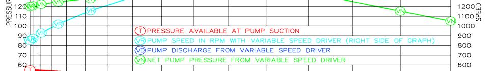
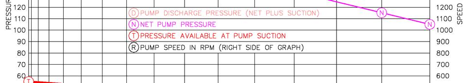
6 SEC Project No November 20, 2006

7 V. DESIGN CONSIDERATIONS SEC Project No November 20, 2006
8 If the variable speed pressure limiting control fails to operate properly, NFPA 20 requires the fire pump to return to rated speed and therefore will operate as a traditional constant speed fire pump. This could cause the pump discharge pressure to exceed the system working pressure. To protect against this possibility, NFPA 20 requires a pressure relief valve to be installed on all variable speed pressure limiting control fire pumps. From the discharge flange of the fire pump to the indicating control valve, system components must be rated for the highest potential pressure. Failure of the variable speed pressure limiting control is anticipated to be an unlikely event and experience may eventually allow the requirement for a pressure relief valve to be removed from NFPA 20. VI. DESIGN FOR HIGH RISE NFPA 14 currently requires the water supply to be capable of providing 500 gpm for the first standpipe and 250 gpm for each additional standpipe up to a maximum of 1000 gpm for a fully sprinklered, light hazard occupancy building. 500 gpm must be available at the topmost two outlets (250 gpm each) at a residual pressure of 100 psi, except NFPA 14 does allow the authority having jurisdiction to lower the pressure requirement to 65 psi. Some municipalities, such as the city of Chicago, require psi at the topmost outlet. NFPA 14 limits the maximum pressure on any part of a standpipe system to 350 psi. NFPA 13 and NFPA 14 allow the use of pressure control valves to reduce pressure to a sprinkler or standpipe system. However, currently, the use of master pressure reducing valves (a single pressure reducing that controls the water supply to multiple fire protection systems) is controversial and introduces reliability issues that need further investigation. In addition, some municipalities, such as Chicago, IL prohibit the use of any pressure reducing devices in sprinkler and standpipe systems (except for individual fire hose valves). The following table 1 was prepared to show the effect of utilizing variable speed pressure limiting controlled pumps. The table indicates the number of floors that can be served without the use of pressure control valves: NOTE: The hose valves must be of a pressure reducing type whenever the pressure at the valve exceeds 175 psi. Systems requiring 100psi at the topmost outlet. Systems requiring 65psi at the topmost outlet Using 175 psi rated system components Using 250 psi rated system components Various floor to floor dimensions. Fire pumps that 110% of rated pressure Fire pumps that 120% of rated pressure Fire pumps that 130% of rated pressure The following assumptions were used to develop these tables 1 and 2: The standpipes demand is 1000gpm. The suction pressure at rated flow is 15 psi less than the suction pressure at churn. The water supply at the pump suction is 50 psi static, 35 psi residual, flowing 1000 gpm. The friction loss from the fire pump to the standpipe riser is 2 psi at 1000gpm. This corresponds to flowing 1000gpm through 250 feet of 8-inch thinwall pipe. The friction loss in the standpipe riser is 0.008psi/ft which corresponds to flowing 500gpm through 6-inch pipe. SEC Project No November 20, 2006
9 Static ure Bottom ure Top Table 1 THE EFFECT OF VARIABLE SPEED PUMPS ON STANDPIPE ZONING Churn % Driver Type 1 Rated Pump ure ure Bottom 2 Static ure Top Height of Zone (feet) No of Typical Flr-Flr - (feet) C % V C % V C % V C % V C % V C % V C % V C % V C % V C % V C % V C % V C indicates a constant speed fire pump V indicates a variable speed pressure limiting control fire pump 2 pressure at bottom of riser at a flow of 1000gpm The above table shows the number of floors that can be on a standpipe zone without exceeding the pressure rating of the systems components, and without using pressure control valves. As a minimum, sprinkler system and standpipe components are listed for 175 psi operating pressure. Sprinkler system and standpipe components are available that are listed for 250 psi or 300 psi. It should be noted that not all sprinklers are available with a 250 psi or 300 psi listing, and FM does not list sprinklers for 250 psi. NFPA 14 limits the maximum pressure on a standpipe system to 350 psi. The available sprinklers should be reviewed before deciding to design a standpipe / sprinkler system to a maximum pressure above 175 psi. Using variable speed pumps with a fluctuating water supply is described in the following section, however, it should be noted that a fluctuating water supply would reduce the number of floors that can served by a constant speed pump below what is indicated in Table 1, while, with proper design, a fluctuating water supply would not reduce the number of floors served by a variable speed pump. SEC Project No November 20, 2006
10 For constant speed pumps, the churn pressure has a significant impact on the number of floors that can be on a zone, i.e. a pump that churns at 110% of rated pressure can serve more floors than a pump that churns at 120%. With a variable speed pressure limiting driver, the pump speed (and pressure) can be reduced so that the system is not subjected to the constant speed churn pressure, and the higher churn rated pressures do not affect the number of floors that can be on a zone. The cost impact of a variable speed pump may be significant. Eliminating a standpipe/sprinkler zone in a high riser could reduce the cost of the fire protection system by $70,000-$100,000 by eliminating a fire pump and express risers. As an example a 20 to 25 story building with a typical floor to floor dimension of 12-feet requires a two zone standpipe / sprinkler system with a constant speed fire pump, but only one zone with a variable speed pressure limiting control fire pump. The following table 2 shows calculated static and residual pressures on each floor of a building having a two zone standpipe/sprinkler system, with the zone 2 fire pump arranged in series with the zone 1 fire pump and a typical 12-ft. floor to floor height. Table 2 is based on a maximum standpipe pressure of 250 psi and a maximum express riser pressure of 350 psi. The flow and friction loss assumptions are the same as used for table 1. The pumps used for the calculations are shown at the bottom of table 2. Table 2 Typical Static and ures on a Two Zone Standpipe System Standpipe Zone 1 Standpipe Zone 2 Constant Speed Variable Speed Constant Speed Variable Speed Floor Elevation Static Static Static Static SEC Project No November 20, 2006
11 Table 2 Typical Static and ures on a Two Zone Standpipe System Standpipe Zone 1 Standpipe Zone 2 Constant Speed Variable Speed Constant Speed Variable Speed Floor Elevation Static Static Static Static First Zone 1 Standpipe pressures Zone 2 Standpipe pressures Express Riser Zone 2 Standpipe pressures Zone 1 Constant Speed Fire Pump: 180psi, churn 110% Zone 2 Constant Speed Fire Pump: 90psi, churn 110% Zone 1 Variable Speed Fire Pump: 215psi, churn % Zone 2 Variable Speed Fire Pump: 100psi, churn % The table indicates that a 40 to 47 story building with a typical floor to floor dimension of 12-feet requires a three zone standpipe / sprinkler system with a constant speed fire pump, but only two zones with a variable speed pressure limiting control fire pump. SEC Project No November 20, 2006
12 VII. DESIGN FOR ESFR SPRINKLERS AND FLUCTUATING WATER SUPPLIES In most cases, K-25 ESFR sprinklers can significantly lower the operating pressures for ESFR sprinkler systems. With 25 foot high storage in a 30 foot high building, a K-14 sprinkler requires a minimum pressure of 50 psi, while a K-25 sprinkler requires a minimum pressure of 15 psi. However, the list price of a K-25 ESFR sprinkler is approximately $30.00 per sprinkler higher than a K-14 ESFR sprinkler. If the contractor discount is 50%, the cost differential is approximately a $15.00 per sprinkler. This means in a 100,000 square foot building requiring 1000 ESFR sprinklers, the costs of the sprinklers could be lowered by $15, by providing an additional 35 psi of residual pressure in the water supply. Example: A 40 feet high building with 35 feet high storage a K-14 ESFR sprinkler system must operate a minimum of 12 sprinklers at a minimum pressure of 75 psi, which equates to a minimum flow rate gpm per sprinkler or a minimum of 1455 gpm for the sprinkler system. Adding 5% overage to the sprinkler system flow, and a 250 gpm hose stream allowance, results in a total water demand of approximately 1775 gpm. The water supply must have sufficient pressure to supply a pressure of 75 psi at the most remote sprinkler plus 17 psi to overcome the elevation difference, plus sufficient pressure to overcome the friction loss in the system. While system friction losses can be minimized with large pipes, having psi available for friction loss allows designing a more economical system. This means psi should be available at the base of the riser. The effect of pressure on the pipe size can be understood better by looking at the Hazen- Williams formula for pressure loss in pipes: f = 4.52*Q 1.85 *L 4.52*Q 1.85 *L C 1.85 D 4.87 Or D= ( f*c 1.85 ) (1/4.87) Where f = Friction Loss in psi Q = Flow through pipe in gpm C = Hazen Williams Coefficient (a measure of smoothness), 120 for wet pipe sprinkler systems D = Pipe diameter in inches L = Equivalent pipe length in feet From this formula it can be noted that doubling the pressure available for friction loss does not reduce the allowable pipe by half. In practice the allowable pipe size reduction becomes marginal whenever the pressure available for friction loss exceeds psi. Water supply characteristics vary widely. Some water systems could provide this flow rate with a pressure fluctuation of less than 5 psi, while in other water systems the pressure fluctuation might be 50 or even 100 psi at this flow rate. Seasonal variations also effect the fluctuations. For purposes of showing the effect of a variable speed pressure limiting control fire pump on the available design pressure, we will assume the water supply at the pump suction has a static pressure of 130 psi, a residual pressure 60 psi at a flow rate of 1775 gpm. The building height is 40 feet, the sprinkler system is designed for 1525 gpm, the inside hose stream demand is 100 gpm and the outside hose stream demand is 150 gpm. Currently, K-14 and K-25 sprinklers are listed for a maximum system pressure of 175 psi. If the sprinklers are 40 feet above the fire pump, the maximum fire pump churn pressure is 192 psi. If SEC Project No November 20, 2006


13 the fire pump churns at 120% of its net pump pressure, then the maximum net pump pressure rating that will not exceed the pressure rating of the sprinkler is 50 psi. Table 3 shows the design pressure available at the pump discharge for constant speed pumps. Table 3 Comparison of available design pressures with Constant Speed Fire Pumps Rated Capacity Rated Constant Speed Pump ure Available Discharge ure 1 HP Discharge pressure available with a 150 gpm outside hose demand and 1625 gpm fire pump discharge Static ure 130, ure 60, Flow 1775 gpm, Building height 40 feet Pump Curves For Constant Speed Pumps With a constant speed fire pump, it is frequently impractical to design beyond 110% of the rated flow because of the decline in available pressure. The above table 3 and pump curves shows a psi fire pump provides 13 psi more 1625 gpm than a psi fire pump. SEC Project No November 20, 2006


14 Table 4 Comparison of available design pressures with Variable Speed Fire Pumps Rated Capacity Rated Variable Speed Pump ure Available Discharge ure 1 HP Discharge pressure available with a 150 gpm outside hose demand and 1625 gpm fire pump discharge Static ure 130, ure 60, Flow 1775 gpm, Building height 40 feet However, with a variable speed pressure limiting control fire pump the rated pump pressure can be increased so that a 1250 gpm pump can deliver the same design pressure as a 2000 gpm fire pump when the design flow rate is less than 1875 gpm. This is demonstrated in Table 4 where a psi fire pump can deliver the same pressure at a flow rate of 1625 gpm as a psi, and a psi fire pump. This may reduce the power requirements and pump cost. Pump Curves With Variable Speed Pump VIII. CONCLUSIONS SEC Project No November 20, 2006
15 A. A variable speed pressure limiting controlled fire pump significantly increases the number of floors that can be included in a single standpipe zone without resorting to pressure control valves. Eliminating a standpipe zone in a high rise building could reduce the cost of the standpipe / sprinkler system by $70,000-$100,000 B. Variable speed pressure limiting control fire pumps can significantly increase the pressure available for design without resorting to pressure control valves. Currently, the use of master pressure reducing valves (a single pressure reducing valve that controls the water supply to multiple fire protection systems) is controversial and introduces reliability issues that need further investigation. C. With a constant speed fire pump, it is frequently impractical to design beyond 110% of the rated flow because of the decline in available pressure. A variable speed pressure limiting control fire pump allows increasing the rated pump pressure and makes it possible to design at % of the rated flow. This may allow using a fire pump with a lower rated flow, thereby possibly reducing the power requirements and pump cost. D. Variable speed pressure limiting controlled fire pumps have significant implications on fire pump design, potentially lessening the demand for low churn (<=110%) pumps and allowing the focus to be placed on pump cost and power consumption. Typically, flat curve fire pumps require more horsepower than pumps with steeper curves. Fire protection system designers should work closely with pump system designers to determine the optimal characteristics of fire pumps. E. With proper design, Variable speed pressure limiting controlled fire pumps can accommodate significant pressure fluctuations in the water supply without compromising the fire protection, or reducing the number of floors served by a variable speed pump. Variable speed pumps also make it easier to provide allowances for possible future degradation in the water supply to be designed into the fire protection F. A diesel engine is inherently a variable speed driver where the speed is controlled with a throttle The cost differential between a constant speed diesel engine driver and a variable speed diesel engine driver is small. The controller that changes the characteristics of the electricity sent to the motor is relatively costly. In general, the cost of a variable speed diesel engine driver is less than a variable speed electric motor driver. IX. REFERENCED DOCUMENTS NFPA 13, Standard for the Installation of Sprinkler Systems, NFPA 14, Standard for the Installation of Standpipe and Hose Systems NFPA 20, Standard for the Installation of Stationary Pumps for Fire Protection. NFPA 25, Standard for the Inspection, Testing, and Maintenance of Water-Based Fire Protection Systems. SEC Project No November 20, 2006
Master Control Systems, Inc. Variable Speed Fire Pump Controllers
 Master Control Systems, Inc. Variable Speed Fire Pump Controllers Meets NFPA 20-2019 UL/FM Listed and Approved for fire protections * Pressure Limiting Control * Suction Limiting Control Why Variable Speed?
Master Control Systems, Inc. Variable Speed Fire Pump Controllers
 Master Control Systems, Inc. Variable Speed Fire Pump Controllers Meets NFPA 20-2013 UL/FM Listed and Approved for fire protections 1 Why Variable Speed? Huge Sprinkler System and Standpipe Cost Savings
I T T Pressure Reducing Valve WARNING INSTALLATION, OPERATION, AND MAINTENANCE MANUAL
 INSTALLATION, OPERATION, AND MAINTENANCE MANUAL I-867-4T 867-4T Pressure Reducing Valve HANG THESE INSTRUCTIONS ON THE INSTALLED VALVE FOR FUTURE REFERENCE WARNING Read and understand all instructions
Bermad Pressure Reducing. Model: 42T
 Bermad Pressure Reducing Pilot Operated Pressure Control Valve Model: 42T Installation Operation Maintenance Manual (IOM) REV. 27.7.17 Page 1 of 12 Safety First BERMAD believes that the safety of personnel
TECHNICAL DATA Q= C. Table 1 - Specifications
 September 25, 2013 Pressure Regulation 537a 1. Description The Model B-3 Pilot Operated Pressure Control Valve is a factory assembled unit. The unit consists of a Model J-2 Halar coated Flow Control Valve,
Pumping Systems for Landscaping Pumps, Controls and Accessories. Mark Snyder, PE
 October 21, 2010 Pumping Systems for Landscaping Pumps, Controls and Accessories Mark Snyder, PE Pump Station Design Purpose of Pump Stations Pump stations are designed to boost water pressure from a lower
INSTRUCTOR GUIDE REFERENCES: PUMPING APPARATUS DRIVER/OPERATOR HANDBOOK, FIRST EDITION, IFSTA
 TOPIC: RELAY PUMPING OPERATIONS LEVEL OF INSTRUCTION: TIME REQUIRED: ONE HOUR INSTRUCTOR GUIDE MATERIALS: APPROPRIATE AUDIO VISUAL SUPPORT REFERENCES: PUMPING APPARATUS DRIVER/OPERATOR HANDBOOK, FIRST
TECHNICAL DATA. Table 1 - Specifications
 Page 1 of 6 1. DESCRIPTION Model A-3 Pilot Operated Pressure Control Valves are factory assembled units. Each unit consists of a Model H-2 Halar coated Flow Control Valve, a Speed Control Valve, a Model
TECHNICAL DATA. the Viking Pilot Pressure Regulating Valve 1 Model A-1 Speed Control Assembly: OBSOLETE. the Viking Speed Control Assembly 1
 November 30, 1994 534 a 1. PRODUCT NAME VIKING 2" (50mm), 3" (75mm), 4" (100mm), 6" (150mm) 2. MANUFACTURER THE VIKING CORPORATION 210 N. Industrial Park Road Hastings, Michigan 49058 U.S.A. Telephone:
SIZING OF WATER PIPING SYSTEM
 SIZING OF WATER PIPING SYSTEM (This appendix is informative and is not part of the code.) SECTION AP101 GENERAL AP101.1 Scope. AP101.1.1 This appendix outlines two procedures for sizing a water piping
Model: 720-UL INSTALLATION OPERATION MAINTENANCE. Bermad Pressure Reducing Valve IOM. Model: FP -720-UL Sizes: 2"-12" BERMAD. Application Engineering
 Bermad Pressure Reducing Valve Model: 720-UL INSTALLATION OPERATION MAINTENANCE Application Engineering BERMAD 1. Safety First BERMAD believes that the safety of personnel working with and around our equipment
ESCONDIDO FIRE DEPT TRAINING MANUAL Section DRIVER OPERATOR Page 1 of 14 Hydraulics Revised
 DRIVER OPERATOR Page 1 of 14 HYDRAULICS Hydraulics applied in the dynamic fire ground environment is an art that comes with study and experience. The following describes the factors that must be mastered
Model: 43T. Bermad Pressure Relief Valve
 Model: 43T Bermad Pressure Relief Valve Installation Operation Maintenance Manual () Rev.C1_01.08.17 Page 1 of 10 Safety First BERMAD believes that the safety of personnel working with and around our equipment
TECHNICAL DATA PILOT PRESSURE REGULATED DELUGE SYSTEM CONTROLLED BY PNEUMATIC RELEASE. 1. DESCRIPTION (Refer to Figures 1, 2 or 3.
 Page 1 of 8 1. DESCRIPTION A Viking Pilot Pressure Regulated Deluge System utilizes a Viking Flow Control Valve to control water flow into the deluge system. The flow control valve must be installed with
SIZING OF WATER PIPING SYSTEM
 SIZING OF WATER PIPING SYSTEM The provisions contained in this appendix are not mandatory unless specifically referenced in the adopting ordinance. E101.1 Scope. SECTION E101 GENERAL E101.1.1 This appendix
TECHNICAL DATA PILOT PRESSURE REGULATED DELUGE SYSTEM CONTROLLED BY ELECTRIC RELEASE 1. DESCRIPTION 2. LISTINGS AND APPROVALS 3.
 Page 1 of 8 1. DESCRIPTION A Viking Pilot Pressure Regulated Deluge System utilizes a Viking flow control valve to control water flow into the deluge system. The flow control valve must be installed with
Irrigation System Winterization and Pressurization Procedures
 Irrigation System Winterization and Pressurization Procedures Introduction Any time that an irrigation system is filled and pressurized, or when the system is drained and water flushed from the system,
BACK PRESSURE / SUSTAINING
 In many liquid piping systems, it is vital that line pressure is maintained within relatively narrow limits. This is the function of the 108 Pressure Relief / Back Pressure Series of the OCV control valves.
BACK PRESSURE / SUSTAINING
 SPECIFICATIONS DIMENSIONS In many liquid piping systems, it is vital that line pressure is maintained within relatively narrow limits. This is the function of the 108 Pressure Relief / Back Pressure Series
SINGLE VALVE WITH LOW-FLOW BYPASS
 CONTROL VALVES Pressure Reducing Valve Sizing Guide Sizing pilot operated reducing valves is not a complicated process. It starts with determining requirements and following these guidelines in valve size
1 Exam Prep. Tabs and Highlights
 1 Exam Prep NFPA 14: Standard for the Installation of Standpipe and Hose Systems Tabs and s These 1 Exam Prep tabs are based on the NFPA 14: Standard for the Installation of Standpipe and Hose Systems,
Data Sheet Issue A
 Features 1. Differential latching clappertype, lighweight, dependable construction. 2. Low Air Pressurized System, 8 psi -to- 26 psi (0,6 bar to- 1,8 bar) 3. Reset externally. Cover removal is not required.
TECHNICAL DATA. Q = C v P S
 Page 1 of 13 1. DESCRIPTION The Viking 6 Model G-6000 Dry Valve Riser Assembly consists of a small profile, light weight, pilot operated valve that is used to separate the water supply from the dry sprinkler
Model 420-HY Pressure Regulating Hydrant Valve
 Model 420-HY Pressure Regulating Hydrant Valve INSTALLATION OPERATION MAINTENANCE 1. Safety First BERMAD believes that the safety of personnel working with and around our equipment is the most important
Apparatus Operator Refresher Training Program
 Division of Training In-Service Training Program Apparatus Operator Refresher Training Program 1 Single Engine / Single Line Operation Refresher Evolution #1 Objective: Charging single handlines at correct
ELKHART BRASS MANUFACTURING COMPANY
 ELKHART BRASS MANUFACTURING COMPANY INSTALLATION and OPERATING INSTRUCTIONS for MODEL UP PRESSURE RESTRICTING HOSE VALVES I. Models and Sizes Covered: UP-20, 1-1/2" size UP-25, 1-1/2" size UP-20, 2-1/2"
Hydronic Systems Balance
 Hydronic Systems Balance Balancing Is Misunderstood Balancing is application of fundamental hydronic system math Balance Adjustment of friction loss location Adjustment of pump to requirements By definition:
Model DDX-LP Dry Pipe Valve System 8 (200mm) Features. Differential latching clapper-type, lighweight, dependable construction.
 Features. Differential latching clapper-type, lighweight, dependable construction.") Bulletin 335 Model DDX-LP Dry Pipe Valve System 8 (200mm) Bulletin 335 Features 1. 2. 3. 4. 5. 6. 7. 8. 9. 10. 11. 12. Differential latching clapper-type, lighweight, dependable construction. Low Air Pressurized
Bulletin 335 Model DDX-LP Dry Pipe Valve System 8 (200mm) Bulletin 335 Features 1. 2. 3. 4. 5. 6. 7. 8. 9. 10. 11. 12. Differential latching clapper-type, lighweight, dependable construction. Low Air Pressurized
FIRE LOGISTICS AND MATH EDUCATION A Rumpke Public Outreach Program
 FIRE LOGISTICS AND MATH EDUCATION A Rumpke Public Outreach Program Welcome & Introductions Identify emergency exits to all participants. Identify location of restroom facilities. Cover any other related
Water Hammer In Irrigation Systems 1
 CIR828 1 G. A. Clark and D. Z. Haman 2 Irrigation system design includes pump sizing and selection, valve sizing and selection, and pipe sizing as well as the proper selection and placement of many other
TECHNICAL DATA 3 MODEL G-3000 DRY VALVE RISER ASSEMBLY
 Page 1 of 13 1. DESCRIPTION The Viking 3 Model G-3000 Dry Valve Riser Assembly is equipped with a small profile, light weight, pilot operated valve that is used to separate the water supply from the dry
TECHNICAL DATA. Q= Cv S
 Page 1 of 13 1. DESCRIPTION The Viking 4 inch Model G-4000 Dry Valve Riser Assembly consists of a small profile, light weight, pilot operated valve that is used to separate the water supply from the dry
TECHNICAL DATA. Page 1 of 12
 Page 1 of 12 1. DESCRIPTION The Viking Regulating Valve is a direct-acting, single-seated, spring-loaded diaphragm valve. When installed as a pilot regulating valve on a Viking Model H or J Flow Control
This portion of the piping tutorial covers control valve sizing, control valves, and the use of nodes.
 Piping Tutorial A piping network represents the flow of fluids through several pieces of equipment. If sufficient variables (flow rate and pressure) are specified on the piping network, CHEMCAD calculates
Air Eliminators and Combination Air Eliminators Strainers
 Description Air Eliminators and Combination Air Eliminator Strainers are designed to provide separation, elimination and prevention of air in piping systems for a variety of installations and conditions.
TUTORIAL. NPSHA for those who hate that stuffy word. by Jacques Chaurette p. eng. copyright 2006
 TUTORIAL NPSHA for those who hate that stuffy word by Jacques Chaurette p. eng. www.lightmypump.com copyright 2006 page.2 NPSHA for those who hate that stuffy word This article follows the same approach
TECHNICAL DATA. than the water inlet pressure to the concentrate
 Foam102a 1. DESCRIPTION The Viking Low Flow Foam/Water proportioning system, is a UL Listed and FM Approved system, for use with 3M foam concentrates. This system consists of a standard wet pipe sprinkler
TECHNICAL DATA Q = C. v P S. 2 Model G-2000 Dry valve. Page 1 of 13
 Page 1 of 13 1. Description The Viking 2 Model G-2000 Dry Valve Riser Assembly consists of a small profile, light weight, pilot operated valve that is used to separate the water supply from the dry sprinkler
Pipe Thread Connection 1/2 inch NPT. Friction Loss Refer to Figure 3
 Worldwide Contacts www.tyco-fire.com Model B-1 Pipe Line Strainer General Description The Model B-1 Pipe Line Strainers (Ref. Figures 1 and 2) are designed for installation in the water supply connection
Features. Model DDX-LP Dry Pipe Valve System 4 (100mm), 6 (150mm) & 165mm Sizes
, 6 (150mm) & 165mm Sizes") Bulletin 357 Rev. E Model DDX-LP Dry Pipe Valve System 4 (100mm), 6 (150mm) & 165mm Sizes Bulletin 357 Rev. E Features 1. 2. 3. 4. 5. 6. 7. 8. 9. Differential-type valve, lightweight, dependable construction.
Bulletin 357 Rev. E Model DDX-LP Dry Pipe Valve System 4 (100mm), 6 (150mm) & 165mm Sizes Bulletin 357 Rev. E Features 1. 2. 3. 4. 5. 6. 7. 8. 9. Differential-type valve, lightweight, dependable construction.
MATH AND MAINTENANCE FOR PUMPS AND BLOWERS TRAINING SEMINAR
 MATH AND MAINTENANCE FOR PUMPS AND BLOWERS TRAINING SEMINAR FORCE WEIGHT OF WATER MEASURED IN POUNDS PRESSURE = FORCE PER UNIT AREA WEIGHT PER UNIT AREA PRESSURE (PSI) = FORCE (LBS) / AREA (IN 2 ) P (PSI)
A centrifugal pump consists of an impeller attached to and rotating with the shaft and a casing that encloses the impeller.
 Centrifugal pump How centrifugal pumps work A centrifugal pump consists of an impeller attached to and rotating with the shaft and a casing that encloses the impeller. In centrifugal pump, liquid is forced
Genie Supreme Model 123 Installation & Operation Instructions
 Genie Supreme Model 123 Installation & Operation Instructions Manufacturing Contact Information A+ Corporation, LLC Call for expert product application assistance: 41041 Black Bayou Rd. Gonzales, LA 70737
22. Specialty Valves.
 22. Specialty Valves. a. Types of Specialty Valves. 1) Use of the following specialty valves is covered in this section: Altitude Valve, Pressure Reducing Valve, Pressure Relief Valve, Swing Check Valve,
III. Identify the initial installation requirements for standpipe systems
 Design Basic Design Requirements 1. Must provide 500 GPM at 65 PSI to the highest most remote standpipe riser outlet. 2. 250 GPM for each additional standpipe total not to exceed 2500 GPM III. Identify
Genie Supreme TM Model 123HP Installation & Operation Instructions
 Genie Supreme TM Model 123HP Installation & Operation Instructions Manufacturing Contact Information A+ Corporation, LLC Call for expert product application assistance: 41041 Black Bayou Rd. Gonzales,
Model B-1 Pipe Line Strainer 3, 4, 6 & 8 Inch (DN80, DN100, DN150 & DN200) 175 psi (12,1 bar) General Description. Technical Data
 175 psi (12,1 bar) General Description. Technical Data") Technical Services: Tel: (800) 381-312 / Fax: (800) 71-5500 Customer Service/Sales: Tel: (215) 362-0700 / (800) 523-6512 Fax: (215) 362-5385 Model B-1 Pipe Line Strainer 3,, 6 & 8 Inch (DN80, DN100, DN150
Technical Services: Tel: (800) 381-312 / Fax: (800) 71-5500 Customer Service/Sales: Tel: (215) 362-0700 / (800) 523-6512 Fax: (215) 362-5385 Model B-1 Pipe Line Strainer 3,, 6 & 8 Inch (DN80, DN100, DN150
Data Sheet Issue A
 Features 1. Differential-type valve, lightweight, dependable construction. 2. Low Air Pressurized System, 10 psi -to- 26 psi (0,7 bar -to- 1,8 bar). 3. Reset externally.cover removal is not required. 4.
LAKOS Waterworks. PWC Series Sand Separators. Installation & Operation Manual LS-829 (10/12)
") LAKOS Waterworks PWC Series Sand Separators Installation & Operation Manual LS-829 (10/12) Table of Contents Separator Operation... 3 Individual Model Details.... 4 Flow vs. Pressure Loss Chart 4 Installation
LAKOS Waterworks PWC Series Sand Separators Installation & Operation Manual LS-829 (10/12) Table of Contents Separator Operation... 3 Individual Model Details.... 4 Flow vs. Pressure Loss Chart 4 Installation
The Discussion of this exercise covers the following points: Pumps Basic operation of a liquid pump Types of liquid pumps The centrifugal pump.
 Exercise 2-3 Centrifugal Pumps EXERCISE OBJECTIVE In this exercise, you will become familiar with the operation of a centrifugal pump and read its performance chart. You will also observe the effect that
The Shand & Jurs Model Vapor Guard Tank Blanketing Valve
 Lower maintenance due to fewer parts Occupies less space, less stress to tank Teflon is inert to most chemicals; extends service life Simplifies and lowers maintenance cost Optimizes flow of blanketing
FIREGROUND HYDRAULICS
 INTRODUCTION This section is designed to give pump operators a quick and fairly easy process for determining fire ground hydraulics. Supplying water is a critical part of the control, and the efficient
TECHNICAL DATA. Dry 132a. October 1, 2008
 October 1, 2008 Dry 132a 1. Description Viking High Pressure (HP) Dry Systems utilize a Viking Model E or Model F Deluge Valve to control the water supply to system piping equipped with closed sprinklers.
TECHNICAL DATA. Q = C v P S
 January 6, 2012 Preaction 348a 1. Description Viking supervised Surefire Preaction Systems utilize the Viking G-6000P Valve. The small profile, lightweight, pilot operated Viking G-6000P Valve comes complete
TECHNICAL DATA. Q = C v P S
 January 6, 2012 Preaction 331a 1. Description Viking supervised Double-Interlocked Electric/Pneumatic Release Preaction Systems utilize the Viking G-3000P Valve. The small profile, lightweight, pilot-operated
TECHNICAL DATA. Q = C v P S
 January 6, 2012 Preaction 333a 1. Description Viking supervised Surefire Preaction Systems Utilize the Viking G-3000P Valve. The small profile, lightweight, pilot-operated Viking G-3000P Valve comes complete
Memorandum. Dr. Wilbert Odem, Dr. Paul Trotta, and Mr. Justin Ramsey. From: Timothy Mahon, Patrick Belsheim, and Ali Alrayyes.
 Memorandum To: Dr. Wilbert Odem, Dr. Paul Trotta, and Mr. Justin Ramsey From: Timothy Mahon, Patrick Belsheim, and Ali Alrayyes Date: 10/17/2013 Re: Routes Decision Matrix Decision Matrix Methodology The
Acoustical Modeling of Reciprocating Compressors With Stepless Valve Unloaders
 Acoustical Modeling of Reciprocating Compressors With Stepless Valve Unloaders Kelly Eberle, P.Eng. Principal Engineer keberle@betamachinery.com Brian C. Howes, M.Sc., P.Eng. Chief Engineer bhowes@betamachinery.com
APPENDIX A RECOMMENDED RULES FOR SIZING THE WATER SUPPLY SYSTEM CHART A 1.2 FRICTION LOSSES FOR DISK-TYPE WATER METERS 1-1/2"
 RECOMMENDED RULES FOR SIZING THE WATER SUPPLY SYSTEM Because of the variable conditions encountered, it is impractical to lay down definite detailed rules of procedure for determining the sizes of water
TECHNICAL DATA. Q = C v P S
 Preaction 346a 1. Description The 6 Model G-6000P Electric Release Preaction System Riser Assembly can be used as a Single Interlock Preaction System with Electric Release, or as a Double Interlock Preaction
TECHNICAL DATA. Trimpac 244a. September 16, 2013
 September 16, 2013 Trimpac 244a 1. DEsCrIpTION DESCRIPTION TRIMPAC Model B-1 and B-1B is a factory-assembled trim package with an electric release module in a metal enclosure. The standard trim normally
appendix a recommended rules For sizing the water supply system PRE-PRINT Chart a 1.2 FriCtion losses For Disk-type water Meters
 recommended rules For sizing the water supply system Because of the variable conditions encountered, it is impractical to lay down definite detailed rules of procedure for determining the sizes of water
TECHNICAL DATA. TRIMPAC Model B-5 & B-5B
 September 16, 2013 Trimpac 250a 1. DESCRIPTION DEsCRIPTIoN is a factory assembled trim package for a ed an electric/pneumatic release module in a metal enclosure. The standard trim normally required on
my SYSTEM A guide to common applications in water distribution systems
 my SYSTEM A guide to common applications in water distribution systems WWW.SINGERVALVE.COM INDEX This short guide is intended to offer guidance on some of the common problems, applications and questions
TECHNICAL DATA. Pressure Regulation 531a. April 24, 2009
 April 24, 29 Pressure Regulation 531a 1. DESCRIPTION The Viking Regulating Valve is a direct-acting, single-seated, spring-loaded diaphragm valve. When installed as a pilot regulating valve on a Viking
Balancing HVAC Hydronic Systems Part 3: Flow Measurement Valves
 Balancing HVAC Hydronic Systems Part 3: Flow Measurement Valves Monday Morning Minutes by Norm Hall, August 20, 2018 The flow balance of a hydronic system is a critical component in the commissioning of
TECHNICAL DATA. Q = C v P S
 January 6, 2012 Preaction 347a 1. Description Viking supervised Double-Interlocked Electric/Pneumatic Release Preaction Systems utilize the Viking G-6000P Valve. The small profile, lightweight, pilot operated
BERMAD Fire Protection Hydraulic Control Valves
 BERMAD Fire Protection Hydraulic Control Valves Control Solutions with the Power to Protect BERMAD - The Company Since its foundation in 1965, BERMAD has focused its efforts on innovation, quality and
TECHNICAL DATA. Trimpac 251a. Spetember 16, 2013
 Spetember 16, 2013 Trimpac 251a 1. DEsCrIpTION DESCRIPTION TRIMPAC Model B-6 and B-6B is a factory assembled trim package for a double interlocked preaction system with an electric/pneu-lectric release
CONTROL VALVE WHAT YOU NEED TO LEARN?
 CONTROL VALVE WHAT YOU NEED TO LEARN? i) The control valve characteristics refers to the relationship between the volumetric flowrate F (Y-axis) through the valve AND the valve travel or opening position
627 Series Pressure Reducing Regulators
 627 Series Pressure Reducing Regulators Introduction The 627 Series direct-operated pressure reducing regulators (Figure 1) are for low and high-pressure systems. These regulators can be used with natural
TECHNICAL DATA NOTICE
 Page 1 of 5 1. DESCRIPTION FomTec BFZ Inductors are used to mix foam concentrate with water when the foam concentrate is supplied from a tank at atmospheric pressure. The BFZ inductor can be installed
Gerald D. Anderson. Education Technical Specialist
 Gerald D. Anderson Education Technical Specialist The factors which influence selection of equipment for a liquid level control loop interact significantly. Analyses of these factors and their interactions
DESIGN DATA A WET PIPE BLADDER TANK FOAM/WATER SYSTEM WITH HYDRAULICALLY ACTUATED DELUGE CONCENTRATE CONTROL VALVE
 February 9, 1998 Foam 101a A BLADDER TANK WITH 1. DESCRIPTION A Wet Pipe Bladder Tank Foam/Water System is a standard wet pipe automatic sprinkler system capable of discharging a foam/water solution automatically
Spring Loaded Regulators Constant Loaded Regulators Twin Parallel Flow Regulators Field Service Regulators
 Product Line Brochure J0B Effective Date 2/01 Spring Loaded Regulators Constant Loaded Regulators Twin Parallel Flow Regulators Field Service Regulators P R O D U C T L I N E O V E R V I E W Regulator
FUNDAMENTAL PRINCIPLES OF SELF-OPERATED PRESSURE REDUCING REGULATORS. John R. Anderson Emerson Process Management Fluid Controls Institute
 FUNDAMENTAL PRINCIPLES OF SELF-OPERATED PRESSURE REDUCING REGULATORS John R. Anderson Emerson Process Management Fluid Controls Institute For pressure control in process or utility applications, control
STRUCTURE S-65 PURPOSE SPILLWAY OPERATION
 STRUCTURE S-65 This structure is a reinforced concrete, gated spillway with discharge controlled by three cable operated, vertical lift gates, and a reinforced concrete lock structure with two pairs of
Expansion Tank Design (Chilled Water)
") Expansion Tank Design (Chilled Water) Table of Contents 1.0 Introduction... 2 1.1 Units... 2 2.0 Disclaimer... 2 3.0 Expansion Tank Types... 2 3.1 Open Tank... 2 3.2 Closed Tank with No Bladder... 3 3.3
Expansion Tank Design (Chilled Water) Table of Contents 1.0 Introduction... 2 1.1 Units... 2 2.0 Disclaimer... 2 3.0 Expansion Tank Types... 2 3.1 Open Tank... 2 3.2 Closed Tank with No Bladder... 3 3.3
SB AXIAL FLOW VALVES
 SB9509.3 AXIAL FLOW VALVES The improved technology for pressure regulation The American Axial Flow Valve provides pressure and flow control in high capacity pipelines. It can be used for pressure regulation,
SUBMITTAL NOTES PROJECT: Ross Model 50RWR-A Pilot Operated Surge Relief Valve with Hydraulic Anticipation. Size: inch / mm
 SUBMITTAL NOTES PROJECT: Ross Model 50RWR-A Pilot Operated Surge Relief Valve with Hydraulic Anticipation Size: inch / mm Every Ross Valve shall be hydrostatically tested for body integrity and tight seating
Colorado Division of Fire Prevention & Control Driver Operator Pumper JPRs (NFPA 1002, 2014 Edition)
") Colorado Division of Fire Prevention & Control Driver Operator Pumper JPRs ( Edition) JPR # Task Initial Certification JPR Requirement: 15 Mandatory Renewal JPR Requirement: 100% of All JPRs (including
Colorado Division of Fire Prevention & Control Driver Operator Pumper JPRs ( Edition) JPR # Task Initial Certification JPR Requirement: 15 Mandatory Renewal JPR Requirement: 100% of All JPRs (including
OIL SUPPLY SYSTEMS ABOVE 45kW OUTPUT 4.1 Oil Supply
 OIL SUPPLY SYSTEMS ABOVE 45kW OUTPUT 4.1 Oil Supply 4.1.1 General The primary function of a system for handling fuel oil is to transfer oil from the storage tank to the oil burner at specified conditions
Wet pipe low flow foam/water system
 December 6, 2010 Foam 14a 1. The Viking Low Flow Foam/Water proportioning system, is a UL Listed and FM Approved system, for use with Viking supplied foam concentrates. This system consists of a standard
HIGH FLOW PROTECTION FOR VARIABLE SPEED PUMPS
 Proceedings of the First Middle East Turbomachinery Symposium February 13-16, 2011, Doha, Qatar HIGH FLOW PROTECTION FOR VARIABLE SPEED PUMPS Amer A. Al-Dhafiri Rotating Equipment Engineer Nabeel M. Al-Odan
TECHNICAL DATA OBSOLETE
 April 9, 2009 Preaction 326a 1. DESCRIPTION Viking supervised Double-Interlocked Electric/Pneumatic Release Preaction Systems utilizing the Viking G-4000P Deluge Valve. The small profi le, lightweight,
SELECTION & APPLICATION
 G O R M A N - R U P P P U M P S SELECTION & APPLICATION OF SELF-PRIMING CENTRIFUGAL PUMPS GRpumps.com G O R M A N - R U P P P U M P S PUMP SELECTION To assist with the selection of self-priming pumps,
APPENDIX A RECOMMENDED RULES FOR SIZING THE WATER SUPPLY SYSTEMS CHART A-1 FRICTION LOSSES FOR DISK-TYPE WATER METERS 1-1/2"
 RECOMMENDED RULES FOR SIZING THE WATER SUPPLY SYSTEMS Because of the variable conditions encountered, it is impractical to lay down definite detailed rules of procedure for determining the sizes of water
Centrifugal Pump Intro
 Pump ED 101 Joe Evans, Ph.D http://www.pumped101.com Centrifugal Pump Intro Part 1 - Elementary Mechanics & Hydraulics What is a Centrifugal Pump? It is a machine that imparts energy to a fluid causing
TECHNICAL DATA. Low-Flow Foam Preaction System with Hydraulically Actuated Concentrate Control Valve.
 Foam 302 a 1. DESCRIPTION (Refer to Figure 1 on page 302 e.) The Viking Low-Flow Foam/Water Proportioning System is a UL Listed and FM Approved system, for use with 3M and Viking brand foam concentrate.
TECHNICAL DATA CAUTION
 Page 1 of 12 1. DESCRIPTION The Viking Model C-2 Pilot Pressure Regulating Valve is a direct-acting, single-seated, spring-loaded diaphragm valve. When installed as a pilot regulating valve on a Viking
THE IMPACT ON ENERGY CONSUMPTION CAUSED BY PRESSURE DROP IN A COMPRESSED AIR SYSTEM
 THE IMPACT ON ENERGY CONSUMPTION CAUSED BY PRESSURE DROP IN A COMPRESSED AIR SYSTEM What is pressure drop in a compressed air utility? Pressure drop is a term used to characterize the reduction in air
Advanced Pump Control for Irrigation Applications
 Advanced Pump Control for Irrigation Applications Paul Nistler VFD Applications Engineer And Julian Atchia Director of Research and Development SJE Rhombus 22650 County Hwy 6 Detroit Lakes MN 56502 Executive
second test was conducted using at 3/4inch nozzle to determine a practical maximum pressure for the pump.
 I am writing this memo to you from the perspective of a fire apparatus operator and tester. Though I offer this collection of my observations and opinions, I do so voluntarily but with the full integrity
Practical Guide. By Steven T. Taylor, P.E., Member ASHRAE
 ractical Guide The following article was published in ASHRAE Journal, March 2003. Copyright 2003 American Society of Heating, Refrigerating and Air- Conditioning Engineers, Inc. It is presented for educational
AIR-OPERATED DOUBLE DIAPHRAGM PUMP USER S MANUAL
 00, 0, 000 00, 000, 00 A. TECHNICAL INFORMATION Model 00 Inlet/Outlet " Air Inlet /" 0 / 000 /" /" 00 /" /" 000 /" /" 00 /" /" Flow Rate GPM/ 0LPM GPM/ 0LPM GPM/ LPM GPM/ LPM GPM/ 0LPM GPM/ 0LPM Maximum
Modulating Valves for Atmospheric, Infrared, and Direct Fired Burners
 BULLETIN MT2035-07/05 Modulating Valves for Atmospheric, Infrared, and Direct Fired Burners M/MR Series M411, M511, M611 M420, M520, M620, MR410, MR510, MR610 MR212D, MR212E, MR212G and MR212J (Flanged),
RICK FAUSEL, BUSINESS DEVELOPMENT ENGINEER TURBOMACHINERY CONTROL SYSTEM DESIGN OBJECTIVES
 RICK FAUL, BUSINESS DEVELOPMENT ENGINEER TURBOMACHINERY CONTROL SYSTEM DESIGN OBJECTIVES The primary design objective for any turbomachinery control system should be to maintain or maximize machine and
DESIGN DATA. Dry 105a. September 5, 2008
 September 5, 2008 Dry 105a 1. Description Dry and Preaction Systems require a dependable source of clean dry air under the proper pressure. The air supply must be adequate to restore normal air pressure
TECHNICAL DATA SINGLE INTERLOCKED PREACTION SYSTEM WITH PNEUMATIC RELEASE
 1 of 10 1. DESCRIPTION (Refer to Figures 1-3.) Viking supervised Single Interlocked Preaction Systems utilize a Viking Deluge Valve and a pneumatically pressurized automatic sprinkler system. The system
CONTROL VALVE SEAT LEAKAGE
 ANSIIFCI 70-2-2006 AMERICAN NATIONAL STANDARD CONTROL VALVE SEAT LEAKAGE \D o N I N I o ~ H U ~ H [/) ~ Fluid Controls Institute, Inc. Spo~sor: Fluid Controls institute, inc. 1300 Sumner Ave Cleveland,