AC / AC+ Centrifugal Pumps Maintenance, Service, and Installation Manual
|
|
|
- Pamela Hoover
- 6 years ago
- Views:
Transcription


1 AC / AC+ Centrifugal Pumps Maintenance, Service, and Installation Manual 1
2 TABLE OF CONTENTS SAFETY 3 INTRODUCTION 4 INSTALLATION 4 PIPING AND CONNECTIONS 5 SUCTION PIPING 5 DISCHARGE PIPING 5 LOCATING VALVES 5 OVERVIEW 6 EXPLODED VIEW 7 PARTS LIST 8 AC+ EXPLODED VIEW 9 ASSEMBLY 10 LEG BRACKET ASSEMBLY 10 ADAPTER ASSEMBLY 10 IMPELLER AND STUB SHAFT 10 STANDARD STUB SHAFT 11 THREADED STUB SHAFT 11 AC+ SHAFT 11 MECHANICAL SEALS 12 D AND F SEAL 12 DG SEAL 13 E SEAL 14 CONVERSION KIT 17 INDUSTRIAL T21 SEAL ASSEMBLY 18 INSPECTION 19 IMPELLER RETENTION 19 CASING ASSEMBLY 20 PUMP CHECK 20 TROUBLESHOOTING 21 TERMS AND CONDITIONS 22 RETURN POLICY 24 2
3 Safety DO NOT attempt to modify any Ampco Pumps product, the AC Series centrifugal pump has been designed to be safe and reliable, to do so could create unsafe conditions and void all warranties. DO NOT place any Ampco Pumps product in an application where general product service ratings are exceeded. Personal injury or machine damage may occur if maintenance and operation personnel do not observe the instructions in this manual. The following DANGER, WARNING, and CAUTION signs and their meanings are used within this manual to avoid serious injury and/or possible damage to equipment.! DANGER Indicates an imminently hazardous situation, and if not avoided, will result in death or serious injury. The word danger is used in the most extreme cases. CODE (Rotating direction CCW)! WARNING Indicates a potentially hazardous situation and, if not avoided, could result in minor or moderate injury. This will also be used to alert against an unsafe operating or maintenance practice. CODE (Guard warning) WARNING ROTATING SHAFT DO NOT OPERATE WITHOUT GUARD IN PLACE! CAUTION Indicates a potentially hazardous situation and, if not avoided, could result in death or serious injury. Safety labels are placed on every pump. DO NOT remove any labeling on any Ampco Pumps product. Replace any label that is missing. 3


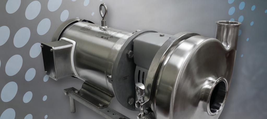
4 Introduction! WARNING Before servicing pump, disconnect electrical power source, carefully relieve all pressure and drain all fluids from pump and connected piping. The AC Series closed-coupled pumps are made up of two sections, the power or drive section and the liquid end or pump section. The pump is mounted to the frame of the drive motor by means of an adapter, and is coupled to the motor shaft. The impeller mounts on the stub shaft and is retained by one of the three methods. The casing is clamped to the adapter, greatly simplifying removal and also permitting positioning of the discharge outlet through 360º. The external balance seal assures long seal life. The drive motor is mounted on a frame having adjustable legs providing simple installation and leveling. Installation Unpacking the Equipment Check the contents and all wrapping when unpacking your equipment. Inspect all parts for damage that may have occurred during shipping. Report any damage to the carrier. Location and Installation The pump unit should be located as close as possible to the liquid source and in a position where the suction piping can be short and direct with minimal fittings. It should also be readily accessible for inspection and cleaning. The pump unit is shipped ready for installation from the factory. To install it, attach a hoist if necessary, loosen the set screws in the adjusting leg brackets, and individually adjust the legs until the pump is leveled. Tighten the set screws. Attach the suction and discharge piping. Be sure suction and discharge piping is properly supported to avoid any strain on the pump casing. Set screw Adjustable Leg Motor leg Bracket 4

5 Piping and Connections General This section provides some do s and do not s of piping which will aid in obtaining the maximum efficiency and service from your pump. Piping should be independently supported at both the suction inlet and discharge outlet. Care should be taken that piping is properly aligned and does not put any strain on the pump casing. The piping should have as few bends as possible. Suction Piping The suction piping should be short and follow a direct route with a minimum number of elbows and fittings. Elbows should be located as far as possible from the suction inlet to prevent head loss due to increased friction. Excessive friction losses in the suction line could result in pump cavitation, poor performance, noise, vibration, damage to equipment, and possible damage to fluid. Whenever possible, the diameter of the piping at the suction inlet should be increased in size, an eccentric tapered reducer should be used instead of a concentric tapered reducer to prevent air pockets from forming and impairing pump efficiency. In turn, the eccentric reducer may be placed at the inlet of the pump and should be positioned so the straight side is up. A horizontal suction pipe must have a gradual rise to the pump. A high point in the suction line will form an air pocket and prevent proper pump operation. All joints in the suction line should be air tight, to prevent air leakage which can reduce pump capacity and efficiency. Discharge Piping Position of the pump discharge is preferably either vertical or top horizontal. The discharge piping should be short and direct with a minimal number of elbows and fittings. Elbows should not be used at the discharge outlet, as the friction encountered would be increased, resulting in head loss. However, use of a larger discharge pipe than recommended may reduce the total pump head, but increase the pump volume, which can cause pump vibration due to overload. Use of a discharge pipe smaller than the pump discharge outlet increases the total pump head but decreases the volume. If a reducer is required on the outlet port of the pump and the discharge is vertical a concentric reducer should be used. If the discharge is horizontal an eccentric reducer should be used and should be positioned so the straight side is down. Locating Valves In suction lift applications where the lift is not very high, it may be desirable to install a foot valve, to facilitate priming and to prevent draining off of the liquid back to the source. A throttling valve should be installed in the discharge piping to control pump flow rate and prevent motor overload. Throttling valve Supports Eccentric reducer Foot valve 5
6 Overview! WARNING Before servicing pump, disconnect electrical power source, carefully relieve all pressure and drain all fluids from pump and connected piping. Before beginning the assembly procedure identify every element that is going to be installed, you can use the exploded view and part list shown on pages 7 and 8. During the assembly you may need the following tools: a. 1, 3/4", 9/16 and 1/2" wrenches b. 1/8, 5/32, 3/16 and 1/4" Allen wrenches c. Rubber mallet d. Vernier caliper, useful with assemble seal type E e. 5/8 & 7/8 socket for impeller nut, for AC+ models f. 3/8 diameter steel rod to hold stub shaft plus, for AC+ models Recently Ampco Pumps added to the AC Series line: AC+ conversion kit, AC+ Series and IC+ Series for specific applications. There are some modifications required to the assembly for each one of these without altering the operation of the equipment. AC+ Conversion Kit The kit is made up of a stub shaft, a stub shaft collar, a shaft key, an impeller, an impeller nut, and front and back impeller gaskets. The collar may use one or two screws according to the pump model. This assembly works exactly the same as a standard assembly from the AC series. AC+ Series The AC+ Series was developed to facilitate the assembly of the AC Series pumps while offering some advantages. The AC+ Series provides more stable performance when mounting the stub shaft onto the motor using a collar. The stub shaft is threaded and offers a more secure mount for the impeller by means of a key and a nut. This advantage is critical to pump longevity while maintaining 3A Sanitary Certification. An ordinary AC Series pump can be turned into an AC+ series with a conversion kit. IC+ Series The IC+ is the same as the AC+ but designed for industrial purposes. It uses an internal mechanical seal denominated T21 which lodges in an industrial back plate. Because of this, the IC+ does not meet the 3A regulations. No other mechanical seal from the AC Series is compatible with the IC+ Series. An ordinary AC Series pump can be turned into an IC+ Series with a conversion kit, an industrial back plate, and a mechanical seal type T21. 6
7 Exploded View 209A M 131A 92 24C 6P 11F 209B Type E water cooled balanced double seal 92A A 75 25B 11P 95 92A 6P Industrial IC+ with internal seal 24C 25B AC/AC+ kit 2P Threaded shaft and Castellated nut P E 25A 71B 24D 17A 80L 17C 6A 80C 11F B K 80A 90 80G 17B 80 DG seal kit 80J 2 80B External balanced seal type D 17K 17J 1 83D 11F 80M 17M 80H 80P 11F 80G 80B 83C 80R 11H 80 11B 80N 83E 6A 6F 25A 24D 24A 24B
8 Parts List External balanced seal type D 11 Backplate D 1 11F Backplate pin 2* 80 Carbon seal 1 80A Cup seal D 1 80B O-ring 1 80C Spring seal D 1 80K Set screw collar seal D 2 80L Drive collar D 1 Clamped-in seat seal type DG 11F Backplate pin 2* 11H Backplate DG 1 17J Gland ring DG 1 17K Bolt/screws gland ring 4** 17M Lock washer 4** 80N Seal seat DG 1 80P PTFE gasket 1*** 80R PTFE gasket 1*** Leg brackets 207 Adjustable leg Adjustable leg bracket 2 209A Set screw 4 209B Bracket mounting screw 4 Kit plus 2P Impeller plus 1 6P Stub shaft plus 1 24C Shaft key plus 1 24D Nut plus 1 25A Front gasket plus 1 25B Back gasket plus 1 92 Drive collar plus 1 92A Bolt drive collar 1** Threaded stub shaft 6A Set screw (shaft) ** 6F Threaded stub shaft 1 24A Castellated nut (impeller) 1 24B Cotter pin (impeller) 1 * Not necessary in some models ** Quantity may vary with model *** Not interchangeable Water cooled balanced double seal type E 11B Backplate E 1 11F Backplate pin 2* 17 Follower 1 17A Machine screw 4** 17B O-ring 1 17C Lock washer 4** 80 Carbon seal 2 80B O-ring 2 80G Cup seal E 2 80H Spring seal E 1 80J Drive collar E 1 80M Set screw drive collar E 2 83C Stuffing box E 1 83D Machine screw 4** 83E O-ring 1 8 AC+ Conversion Kit Conversion kit 1 11F Backplate pin 2* 11P Industrial backplate 1 95 Seal T21 1 Common components 1 Casing 1 2 Impeller 1 6A Set screw (shaft) ** 6E Stub shaft 1 24 Retainer (impeller) 1 40 Deflector 1 71 Adapter 1 71A Adapter pin 2* 71B Adapter mounting screw 4 75 Clamp assembly complete 1 90 Casing gasket Seal guard assembly 1 131A Set screw Water cascade assembly 1 M Motor 1
9 AC Series Maintenance Manual Addendum for AC+ Design Pumps Additional Parts for AC+ Design Key Description Qty 2P AC+ Impeller 1 6P AC+ Stub shaft 1 25 AC+ Impeller nut 1 25A AC+ Impeller nut gasket 1 25B AC+ Impeller back gasket 1 26 AC+ Shaft Collar 1 27 AC+ Impeller Key 1 AC+ Shaft Design Drawing Necessary Equipment 3/8 Diameter Rod For securing haft when tightening/loosening impeller nut 5/8 Socket Wrench For impeller nut AC+ 114 Pumps 7/8 Socket Wrench For impeller nut AC+ 216, 218, 328, & 4410 Pumps Bolt Torques Collars Impeller Nuts 56C/140TC/180TC 15 ft-lbs AC ft-lbs 210TC/250TC 30 ft-lbs AC+ 216/218/328/ ft-lbs 280TC/280TSC/320TC/320TSC 40 ft-lbs 9

10 Assembly By getting to know the configurations of our centrifugal pumps from the AC, AC+, and IC+ Series you can learn to assemble our pumps. Some of the instructions that describe the assembly process correspond to various common components of each of the three series of centrifugal pumps. However, when it is time to actually carry out the assembly of a part unique to a particular series, the assembly manual will adequately point that out (i.e. mechanical seals, conversion kit). It is highly recommended that you resort to the diagram on page 7 to verify the assemblies and sub-assemblies. Leg Bracket Assembly Sets of leg-brackets are optional and can be used to vertically adjust the pump. The size of the brackets (209) and the legs (207) depend upon the NEMA or IEC of the motor. First, complete the primary assembly of the legs and the brackets, using the hexagonal screws (209A) to tighten the legs to the brackets. Next, use the hexagonal screws (209B) to tighten the brackets to the motor (210). You may need to lift the motor to complete this part of the assembly. Adapter Assembly Place the stainless steel adapter on the motor and tighten using four hexagonal screws (71B). The adapter should be accompanied by two adapter pins, which normally come preinstalled. If not, insert them in the corresponding drilled holes. These pins serve to set the backplate (11) to the adapter (71), hooking the backplate onto the adapter pins using the two backplate pins (11F) located on the backplate. Depending upon the pump model and seal type, some backplates do not have pins for reasons of design. Important: The adapter comes with a protective guard (131) which comes attached by a hexagonal screw (131A). It is highly recommended for safety reasons not to operate the pump if this guard is not placed on the adapter. Impeller and Stub Shaft To set the stub shaft onto the motor, it is necessary to place it at the proper distance. To find this position, it is necessary to provide a spacing of seventy one-thousandths of an inch (0.070 in.) between the impeller and the backplate, as shown below in figure A. You can make this adjustment using a Vernier caliper or spacing gauge in. Figure A Spacing of the Impeller and Stub Shaft Depending on the pump model and the seal type, the backplate requires two pins (11F), which serve to hold the backplate in place when mounted on the adapter. The backplate pins should always be placed pointing in a counter-clockwise direction so that the backplate does not slip. When handling the backplate be careful not to damage the contact surface of the mechanical seal or the front side of the backplate. Since we have both standard stub shafts (6E) and stub shafts plus (6P) it is necessary to explain that the former are fixed onto the motor shaft with screws (6A) and the latter with screws that tighten a collar (92) onto the stub shaft. An explanation on how to place the stub shaft onto the motor follows. 10
 in the key-slot located on the shaft of the motor and smoothly slide the stub shaft onto the motor shaft.")
11 Standard Stub Shaft - Before assembly, insert the set screws (6A) into the stub shaft (6E), leaving them loose so as not to penetrate the inner diameter. Then, place the key (provided with the motor) in the key-slot located on the shaft of the motor and smoothly slide the stub shaft onto the motor shaft. At this point, the stub shaft should easily slide on and off of the motor shaft and should freely spin, moving the motor shaft while in contact with the key. Place the backplate onto the adapter and turn it in a counter-clockwise direction, locking the backplate pins (11F) onto the adapter pins (71A). If necessary pull out the stub shaft so that it is still mounted onto the motor shaft. Place the retainer (24) into the stub shaft so that it recedes completely into its slot and insert the impeller onto the stub shaft, making sure that the retainer falls to one side to secure the impeller. Space the back of the impeller at a distance of in. from the face of the backplate and tighten the set screws in order to secure the stub shaft. Threaded Stub Shaft - The assembly process is the same as that of the standard stub shafts, except that in the case of the threaded stub shaft, you must first insert the impeller and tighten the castellated nut (24A). When the castellated nut can go no further, insert the cotter pin (24B) through the drilled hole in the stub shaft, so that it aligns with the slots on top of the castellated nut. Next, bend the ends of the cotter pin so that the castellated nut secures the impeller. Space the impeller at a distance of inches from the backplate and tighten the set screws to secure the stub shaft. Please note that these stub shafts are not sanitary and do not meet 3A regulations. AC+ Shaft - The AC+ stub shafts are secured by the friction between the motor shaft and stub shaft. This friction is created by the AC+ drive collar (92). As you tighten the screw (92A), the drive collar (92) exerts a force upon the stub shaft (6P) which is slotted forcing it to close. For ultimate efficiency, the three slots must be aligned as shown in figure B: 1 - the key slot on the motor shaft, 2 - the slot on the plus stub shaft, 3 - the slot on the drive collar. Slide the drive collar onto the stub shaft until it touches the stub shaft s larger diameter, and slide both parts onto the motor shaft aligning all three slots. You can use an Allen wrench less than 0.125inches to align the three slots. The motor shaft key is not used. Three slots converge Next, place the backplate onto the adapter (71) and turn it in a counter-clockwise direction, pressing it against the adapter so that the backplate pins (11F) lock onto the adapter pins (71A). Figure B AC+ Stub Shaft Assembly BOLT TORQUES LISTED ON PAGE 9 Place the impeller (2P) onto the stub shaft after placing the key (24C) into the key slot on the shaft. Screw on the impeller nut (24D) and tighten until it makes contact with the impeller using a socket (5/8 or 7/8 depending on the model). Space the impeller at a distance of in. from the face of the backplate and tighten the collar screw to set the stub shaft. When tightening the collar, be sure not to turn the shaft or the collar to avoid misalignment with the three slots. IMPORTANT: At this point the adapter is mounted, the stub shaft is fixed on the motor, and the impeller is spaced at a distance of inches from the backplate. Take off the impeller and remove the backplate to begin assembling the mechanical seal. 11
12 Place the deflector (40) in the ridge found on the standard stub shaft. Plus model stub shafts do not use a deflector. Mechanical Seals The T21, is used exclusively with our IC+ Series, specifically in non-sanitary applications. The D is used when the fluid which is going to be pumped is neither corrosive nor abrasive. It is a balanced, external seal, designed to be long-lasting. The F contains a water-cascade assembly to lubricate and cool the seal. The water-cascade assembly is located on one side of the adapter. This seal, although it is sanitary, is very dirty because the coolant tends to drip. The DG seal consists of two parts: one stationary and one rotating. The stationary portion consists of a piece which may be carbon silicone, ceramic, or carbon tungsten, and that is placed in a gland ring. This type of seal is used when the fluid to be pumped is abrasive, corrosive, or contains a product which impedes the seal lubrication. The stationary seal reversible, so flipping the seal is sufficient to continue using it. The E seal is a double-balanced seal cooled by water. This seal is composed of a stuffing box which is filled with fluid (normally water) to cool the mechanical seal. The E seal is used in conditions similar to those of the DG seal but in applications that handle extremely high temperatures (up to 500º F). It can also be used in applications where there exists a vacuum of up to 28 in. of mercury. External-Balanced Seal Types D and F Locate the following pieces: carbon (80), o-ring (80B), D seal cup (80A), D seal spring (80C), D seal drive collar (80L), set screws (80K), and D seal backplate (11). Pre-assemble the set screws, making sure they do not penetrate the inner diameter of the stub shaft and set the o-ring into the carbon so that it sits at the back. Next, place the o-ring and carbon together onto the cup so that the cup s three legs align with the carbon s slots. Then, fit the spring onto the cup so that the tip of the spring is touching a fourth, folded leg on the cup. If necessary rotate the spring to touch the two pieces. When handling the carbon (80), be careful not to bump or scratch the seat of the seal, as this is the face that makes the seal. For best assembly, the drive collar has a pin or key that should fit into a slot in the cup. Use pressure to insert the drive collar, making sure that the pin aligns with the slot as shown in figure C. Slide the entire assembly onto the stub shaft. The o- ring seals the flow of fluid between the pump and the exterior through the mechanical seal by filling the space between the stub shaft and carbon. Slot in the cup Drive collar pin or key Figure C Assembly Seal Type D Carbon s slots Seat of carbon 12
 and fix it with the backplate pins.")
13 The seal will provide a resistance when it slides on, so apply pressure until it has gone onto the stub shaft completely. The position of the drive collar against the o-ring and carbon is critical to prevent leaks. Now, assemble the D seal backplate (11) and fix it with the backplate pins. Push the carbon back with the backplate. Once the backplate has been placed it is necessary to tighten the D seal collar set screws (80L). To do this, you must exert a pressure on the drive collar towards the backplate, so that the pin of the drive collar remains aligned with the slot in the cup. Tighten the set screws once the drive collar has reached its closest point to the o-ring and carbon. The drive collar should stay in its place against the o-ring against the back within the limits of the carbon, as shown in figure D. The spring does not compress entirely. When all parts are in their correct positions, the stub shaft should be able to rotate freely when turned by hand. If it is necessary to use excessive force to turn the stub shaft, check to be sure that the components of the seal have been properly installed and that the drive collar is properly positioned. Spring The o-ring stays trapped at the bottom of the carbon. Figure D Drive Collar Seal Type D Position The F SEAL The water-cascade assembly (132) should be installed on the adapter (71), so that the leak falls upon the seal seat of the carbon, lubricating the seal against the backplate. IMPORTANT: It is necessary to disassemble some of the pump parts for cleaning and sterilizing. For those Ampco Pumps products equipped with D seals, if a CIP (Clean-in-Place) instillation is used, disassembly is not necessary. Do not lubricate the seal with grease or oil; the faces of the seals are lubricated by the fluid that is being pumped. Clamped-In Seat Seal Type DG This seal type consists of two parts: a stationary and a rotating. The rotating part is the D seal assembly. For that reason it is highly recommended that you read the directions above for assembling the D seal before continuing. The stationary part consists of the following elements: DG seal seat (80N), PTFE gasket (80P), PTFE gasket (80R), DG gland ring (17J), lock washers (17M), bolts/screws gland ring (17K), and DG seal backplate (11H). IMPORTANT: Be extra careful when assembling the DG seal. Incorrect spacing between the impeller and backplate can result in dangerous contact between the face of the stationary seal. That contact may wear down the impeller and the seat of the gland ring. A visual inspection following the installation of the impeller is recommended to check the spacing of the impeller and seal. Take the DG backplate (11H), turn it around and place the PTFE gasket (80R) against the seat face. Next, install the seal seat (80N) which is reversible followed by the PTFE gasket (80P) and finally the gland ring (17J). In the seal type DG, the seal seat (80N) is enclosed by the gland ring, which could be made of silicone, tungsten, or ceramic. Please remember that the PTFE gaskets (80P) and (80R) are not interchangeable. 13
 and lock washers (17M). Screw the backplate pins (11F) to the backplate if applicable (figure E).")

14 The seal seat (80N) should be handled with care, the material is extremely fragile. It is important to protect the faces of the stationary seal just as with the backplate, against bumps and scratches. Screw the gland ring into the backplate, using the screws (17K) and lock washers (17M). Screw the backplate pins (11F) to the backplate if applicable (figure E). Tighten the screws until the washers are flattened, any tighter and you may crack the stationary seal. Figure E Stationary Part Seal DG Once the backplate is set onto the adapter, push the drive collar against the backplate to compress the spring. Tighten the set screws to set the seal when the spring no longer moves. Assemble the D seal components onto the stub shaft (as explained on page 12) taking care that the o-ring remains inside of the carbon. Once both pre-assemblies are complete, (the DG seal onto the backplate and that of the D seal), take the backplate and push on the D seal sliding it onto the stub shaft. Be very careful not to hit the DG seal with the end of the stub shaft. Now, set the backplate onto the adapter. Although space appears to be limited, the spring can be compressed until the drive collar completely touches the o- ring. The o-ring stays trapped at the bottom of the carbon. The efficiency of the D and DG seals relies upon the position of the o-ring inside the carbon as well as the full compression of the spring (Figure F). The DG seal is used to handle fluids that crystallize when allowed to settle for a time. When pumping abrasive or corrosive fluids, combine the DG seal with EPDM gaskets. EPDM gaskets are resistant to certain harsh chemicals. For more information, please contact either the plant or your distributor. Push the collar to compress the spring. There is always a space between the stub shaft and collar. Figure F Clamped-In Seat Seal Type DG Assembly Water Cooled Balanced Double Seal Type E. This mechanical seal consists of two balanced, rotating parts, placed into a stuffing box, which is normally flooded to cool the seal. The E seal consists of the following parts: stuffing box E (83C), o-ring (83E), machine screw (83D), follower (17), o-ring (17B), machine screw (17A), and lock washers (17C) for the follower, E seal backplate (11B), backplate pins (11F), spring (80H), drive collar E (80J), set screw drive collar (80M), two carbon seals (80), two o-rings (80B) and two cups (80G). It is recommended to have a caliper on hand to assemble this seal precisely. 14
 in the groove of the collar (17).")
15 The following instructions assume that the adapter is assembled and that the spacing between the impeller and backplate has been set. If not, we recommend you refer to that section of the assembly directions. Place the o-ring (17B) in the groove of the collar (17). Attach the backplate pins (11F) to the backplate (11B), take the o-ring (83E) and place it in the slot of the stuffing box (83C) and place both parts against the backplate. Screw on the stuffing box (o-ring in place) to the backplate with the machine screw (83D). Be sure to protect the faces of the backplate during assembly. Pre-assemble the set screws (80M) onto the E drive collar (80J) without penetrating the inner diameter. Slide the E drive collar, along with the o-ring, onto the stub shaft (6E), with the o-ring pointing towards the tip of the stub shaft. Pre-assemble the o-rings (80B) in the carbon seals (80), pushing them to the back of the seat. Place each carbon seal onto a cup (80G). These are the two rotating components that will be balanced on the spring (80H) inside the stuffing box (83C). Be very careful when handling the carbon seals, especially when handling the seal seat, because it is crucial in maintaining contact between the stuffing box and backplate. Carefully slide the carbon seal, o-ring, and cup onto the stub shaft, using the E drive collar (80J) as a support for the o-ring. The seal seat of the carbon should be able to touch the follower (17). Slide the drive collar onto the stub shaft. Next, secure the drive collar to the stub shaft at the proper distance (Regardless of stub shaft model). For help, refer to Table A, which indicated the spacing values, then take the Vernier caliper and use it to measure that distance as shown in figure G. X Model Distance X / There is always a space between the stub shaft and collar Table A. Distance X for every models Figure G Positioning of the drive collar type E Locate the drive collar E (80J) and secure it with the set screws (80M). Place the spring (80H) onto the cup (80G). The drive collar has two pins, which drag both cups along the rotations of the stub shaft. Each cup has a folded leg that initiates traction with the drive collar. Try to place the pins before the legs of the cups, facing in a counter-clockwise direction (Figure H). Now, install the second set of the cup, o-ring, and carbon onto the stub shaft. Put the end of the spring into the second cup, just as you did with the first. The seal seat of the second carbon seal should point towards the backplate (11B). Take the sub-assembly of the backplate (11B) with the stuffing box (83C) and place it onto the adapter (71), making sure that the stuffing box does not hit the components mounted on the stub shaft. Push in and rotate the backplate until the pins are locked. If this model does not have backplate pins, place the casing gasket (90) into the slot on the backplate, put on the casing (1) and tighten using the clamp assembly (75) to secure the backplate. 15


16 IMPORTANT: When you mount the backplate onto the adapter, the seal may supply resistance. If this resistance is too much, check the seal assembly and be sure the drive collar has been located correctly. The efficiency of the E seal relies on the p r o p e r installation of the drive collar. The space in the stuffing box should contain both carbons in a balanced state of pressures and distances. Figure I The drive collar pins drag the washers as well the carbons. The drive collar must be centered inside the stuffing box O-ring O-ring Figure H The Stub Shaft turns Counter-Clockwise Tighten the screws until the washers are flattened Figure I Water Cooled Balanced Double Seal Type E The next step is to close the stuffing box. To do so, you need to pull the follower against the backplate. Use the machine screws (17A) and lock washers (17C) to close it, tightening until the lock washers are flattened. The screws on a circular arrangement can be tightening across and varying positions when screwing. It is recommended to set the backplate so that the 1/8 NPT drill-holes on the stuffing box, point upward and with a 45º inclination from the horizontal plane, as shown in Figure J. 45º The water should enter through one connection and leave through another, moving through the stuffing box and in the process, cooling it. The ideal quantity of water will depend upon the temperature of your application. For vacuum applications it is recommended to use a flow of 10 drops per minute, while maintaining a temperature of 176º F inside the seal around 3 gallons per hour are required. Figure J Position of the 1/8 NPT drill-holes IMPORTANT: When servicing pumps with D, DG, F, or E seals, inspect all disposable parts such as: carbon seals (be sure they have no bumps or scratches) and o-rings (they should maintain a circular form and should not be bitten). In the case of abrasive fluids, use EPDM material for all gaskets and o-rings. When dealing with high temperatures, use Viton. Springs are not subject to wear because of tension or compression, except in extreme cases. Carbon seals made of silicone, tungsten, or ceramic are very fragile but resist abrasive and corrosive fluids. 16


, bolt drive collar (92A), stub shaft plus (6P), stub shaft key (24C), back impeller gasket (91A), front")
17 Conversion Kit Assembly IMPORTANT: These instructions assume that the adapter has been mounted to the motor and the impeller has been spaced at a distance of in. from the backplate. If you have not assembled the stub shaft, refer to the assembly section before proceeding. Remember that it is imperative you align the key slot on the motor shaft, the slot on the stub shaft, and the slot on the drive collar to properly mount the stub shaft, Figure B. We can easily convert an AC Series standard pump to an AC+ Series pump with a conversion kit. The AC+ Series is 100% sanitary and meets the sanitary regulations set by 3A. The AC+ Series is an improved design that maintains a tighter, sturdier assembly. To assemble a kit, you must first find the following components: drive collar plus (92), bolt drive collar (92A), stub shaft plus (6P), stub shaft key (24C), back impeller gasket (91A), front impeller gasket (91B), impeller plus (2P), and impeller nut (24D). IMPORTANT: In some cases, the front and back gaskets are interchangeable (only models 218/328 and 4410). Figure K Conversion Kit with Seal Type D The conversion kit is compatible with D, DG, F, and E seals. The only differences are the method of installing the stub shaft to the motor and the retention of the impeller, Figure K. IMPORTANT: Before continuing with the assembly of the conversion kit put together the seal type that you are going to use. Once you have put together the seal and secured the backplate, place the back gasket for the impeller plus (91A) into the groove on the stub shaft plus (6P). Next, place the shaft key (24C) into the key slot on the stub shaft. Slide the impeller plus (2P) onto the stub shaft and past the key, using the impeller key slot, making sure that the back gasket remains in its groove. Insert the front impeller gasket (91B) into the groove on the impeller nut (24D). Screw the impeller nut onto the stub shaft making sure that the front gasket remains in the groove on the impeller nut. Tighten using a socket (5/8 or 7/8, depending on the model) to assemble. Use a 3/8 diameter steel rod to secure the stub shaft when tightening. The impeller nut should be tightened at 40 ft-lb, Figure L. Shaft key plus Back impeller gasket Front impeller gasket Figure L Gaskets isolate the fluid from the thread and key Impeller nut 17
18 IMPORTANT: Never start the pump without the stub shaft key in place, as doing so may lead to friction between the impeller and stub shaft, causing seizure between the parts. Do not forget to adjust the screws and impeller nut before starting up the pump. If you are using CIP (Cleanin-Place) installations, there is no need to disassemble the AC+ conversion kit. The threads of the stub shaft and impeller nut are sealed from fluid entry by the front and back gaskets, and therefore are sanitary. Industrial T21 Seal Assembly IC+ Series The IC+ series (industrial centrifugal pumps) is another configuration of the AC and AC+ Series designed for non-sanitary applications. The IC+ Series does not meet 3A sanitary regulations. An IC+ Series pump is composed of the same parts as a standard AC Series pump, but requires the conversion kit to set the stub shaft and install the impeller. It also uses an industrial internal seal T21 and a specially designed backplate. The T21 seal generally comes as a kit and is disposable, so if one of the parts is damaged you need to replace the entire kit. IMPORTANT: These assembly instructions assume that the adapter has been mounted to the motor and the impeller has been placed at a distance of in. from the backplate. If the stub shaft has not yet been assembled, please return to assembly section before continuing. To assemble the T21 seal (95), please identify the following parts: Rubber gasket (type o-ring) Primary cup Cup (Elastomer) Ceramic seal seat Cup reinforcement Spring Carbon seal seat Figure M Industrial Seal Type T21 The ceramic seal, which is reversible, goes inside the elastomer cup, which gets inserted into the industrial backplate (11P). Place the reversible cup reinforcement into the primary cup so that the legs align with the slots. Place the rubber gasket (o-ring) into the primary cup so that it sits at the back and holds in the cup. Now, place the carbon into the cup, taking care not to damage the seal seat, so that the carbon aligns with the groove in the cup. Place the backplate with the ceramic seal seat in place on the adapter, taking care not to bump the seal on the stub shaft threads. Slide the sub-assembly of the carbon and cup onto the stub shaft until it touches the ceramic seal. Place the shaft key (24C) and back gasket (91A) in their respective slots. Force the spring into the cup and slide the plus impeller (2P) over the shaft key and onto the stub shaft and push. Place the front gasket (91B) in the groove on the impeller nut (24D) and tighten the assembly. 18

19 INSPECTION! WARNING Before inspecting your pump s assembly, double-check that the electric supply is disconnected, and that there is no supply of pressure or fluid into the piping. Before continuing please check that all bolts/screws and set screws have been tightened. Rotate the stub shaft by hand, using the impeller. The stub shaft should rotate easily. If something is interfering with its rotation, inspect all parts to verify correct assembly (stub shaft, seal, backplate, etc.). Impeller Retention Standard Stub Shafts - Find the following parts: impeller (2), retainer (24), and standard stub shaft (6E). Place the retainer into the drilled hole atop the stub shaft so that it is completely receded. When you have placed the impeller at the back, make sure that the retainer falls to lock in the impeller. Figure N. Threaded Stub Shafts - Find the following parts: impeller (2), castellated nut (24A), threaded stub shaft (6F), and cotter pin (24B). Slide the impeller onto the tip of the stub shaft and push to the back. Screw on the castellated nut until it touches the impeller. Tighten more with the cotter pin in the grooves atop the castellated nut and bend back the ends of the pin to lock, Figure O. AC+ Series - Find the following parts: impeller plus (2P), impeller gaskets (back 91A and front 91B), impeller nut (24D), shaft key (24C), and stub shaft plus (6P). Place the shaft key into the stub shaft and place the back impeller gasket (91A) into the groove on the shaft. Slide the impeller onto the shaft until it reaches the back and place the front gasket (91B) onto the impeller nut, screwing the nut (24D) onto the impeller. Make sure the gaskets stay in place, Figure P. BOLT TORQUES Collars Impeller Nuts 56C/ 140TC/ 180 TC 15ft-lbs AC ft-lbs 210TC/ 250TC 30ft-lbs AC+216/ 218/328/ ft-lbs 280TC/ 280TSC/ 320TC/ 320TSC 40ft-lbs Figure N Standard stub shafts and impeller pin Figure O Threaded stub shaft and castellated nut Figure P Stub shaft plus and Impeller nut 19
 onto the groove on the backplate (11, 11B, 11H or 11P), depending on the")
 and place it onto the adapter, positioning the discharge at the desired location.")


20 Casing Assembly Once the impeller has been installed, the casing must be mounted. Place the casing gasket (90) onto the groove on the backplate (11, 11B, 11H or 11P), depending on the seal type. Take the casing (1) and place it onto the adapter, positioning the discharge at the desired location. Take the clamp assembly (75) and place it around the casing. Tighten the clamp to close the casing so that it is level around the perimeter. A rubber mallet may be helpful when installing the casing. Pump Check Check that the motor turns in a counter-clockwise direction. Keep the suction line flooded and the mechanical seal lubricated with the fluid which is going to be pumped. Never operate the pump dry or it may damage the seal. Maintain a sufficient NPSH available in the suction line (please see the section on piping). 20
21 Troubleshooting Ampco Pumps products are relatively easy to maintain with the exception of the sanitary process. Just as with any other element of machinery, problems may arise. This section offers a guide for identifying and correcting the majority of the pumping problems. For problems with you motor, contact the manufacturer directly for best assistance. The following table illustrates the problems and probable causes, assuming that the pump was correctly selected for a specific application. If none of the listed solutions provided in the table resolves the problem, the most likely cause is cavitation. Cavitation may be caused by an incorrect pump selection and its symptoms include: excessive noise, insufficient pressure, fluid leak, and vibration. If these symptoms are present, please re-evaluate your application. 1. NO FLOW SOLUTIONS a) Motor speed too low a) Check electric connections and motor b) Incorrect rotation direction b) Reverse one of the motors three phases, and if the c) Obstruction in discharge piping or closed valves direction does not change, contact the manufacturer c) Remove obstruction and open valves 2. INSUFICIENT FLOW a) Motor speed too low b) Incorrect rotation direction c) Obstruction in discharge piping or closed valves d) Impeller damaged 3. EXCESSIVE POWER CONSUMPTION a) Motor speed too high b) Impeller damaged c) Motor shaft is bent or worn 4. EXCESSIVE NOISE a) Magnetic problem with motor b) Motor bearings damaged c) Foreign particles in impeller d) Impeller damaged e) Cavitation 5. EXCESSIVE VIBRATION a) Pump is not leveled b) Impeller damaged c) Piping lacks supports d) Cavitation 6. FLUID LEAK a) Disposable o-rings b) Disposable carbons c) Insufficient seal compression d) Damaged casing suction/discharge e) Disposable casing gasket f) Loose clamp assembly a) Check electric connections and motor b) Reverse one of the motors three phases, and if the direction does not change, contact the manufacturer c) Remove obstruction and open valves d) Replace impeller a) Motor wires are bad, replace motor b) Remove casing and replace impeller c) Replace motor shaft a) Consult motor manufacturer b) Replace bearings c) Remove casing and extract particles d) Replace impeller e) Check system s available NPSH a) Level the pump b) Replace the impeller c) Support suction and discharge piping d) Check system s available NPSH a) Replace o-rings b) Replace carbons c) Replace spring d) Replace casing e) Replace casing gasket f) Tighten clamp assembly 21
22 AMPCO PUMPS Made of SELECTED corrosion-resistant alloys TERMS AND CONDITIONS OF SALE 1. ENTIRE AGREEMENT. This document contains all of the terms and conditions of the agreement ( the agreement ) between Ampco Pumps Company, Inc. ( Seller ) and the purchaser ( Purchaser ) of the Products ( Products ) to be sold to Purchaser, to the exclusion of any other statements and agreements, and to the exclusion of any terms and conditions incorporated in Purchaser s order or other documents of Purchaser. Seller s acceptance of Purchaser s order is expressly conditioned on Purchaser s acceptance of the terms and conditions contained herein, and Purchaser, upon placing an order, is presumed to have accepted all the terms and conditions without modification. No alteration, waiver, modification of or addition to the terms and conditions herein shall be binding on Seller unless set forth in writing and specifically agreed to by an officer of Seller No course of dealing, usage of trade or course of performance will be relevant to supplement or explain any terms used in the agreement. All offers to purchase, quotations and contracts of sale are subject to final acceptance by Seller at its home office at Milwaukee, Wisconsin. 2. PRICES. Prices for Products manufactured by Seller pursuant to written accepted orders will remain firm for thirty (30) days from the date of any subsequent price change. 3. TERMS OF PAYMENT. Standard terms are ½% 10 days, 30 days net, from date of invoice unless otherwise stated. If, in the judgment of Seller, the financial condition of Purchaser at any time does not justify continuance of production or shipment on the terms of payment specified, Seller may require full or partial payment in advance. In cases of delays in payment, Seller reserves the right to charge interest on delinquent balances at the rate of 1 ½% per month. 4. DELIVERY. Except as otherwise provided expressly stated in the agreement, Products are sold F.O.B. Milwaukee. Seller will use reasonable commercial efforts to fill orders within the time stated, but the stated delivery date is approximate only, and Seller reserves the right to readjust shipment schedules without liability. Acceptance by Purchaser of the Products waives any claim for loss or damage resulting from a delay, regardless of the cause of the delay. Except as otherwise provided herein, Seller will not be responsible for freight, transportation, insurance, shipping, storage, handling, demurrage or similar charges. Claims by Purchaser for shortages in the Products must be made to Seller in writing within ten (10) days after date of receipt of the Products. No such shortage shall entitle Purchaser to withhold payment for Products which were received by Purchaser. Each such claim shall set forth in detail the basis and amount of such claim. 5. TAXES AND FEES. Seller shall pay all present and future sales, excise, privilege, use or other taxes, customs duties, and all other fees or other costs, imposed by any federal, state, foreign, or local authorities arising from the sale, purchase, transportation, delivery, storage, use or consumption of the Products or will, if applicable, provide Seller with an appropriate exemption certificate. Seller shall be under no obligation to contest the validity of any such taxes or to prosecute any claims for refunds or returns. 6. INSTALLATION. The Products shall be installed by and at the expense of Purchaser. 7. LOSS, DAMAGE OR DELAY. Seller will not be liable for loss, damage or delay resulting from causes beyond its reasonable control, including, without limitation, strikes or labor difficulties, lockouts, acts or omissions of any governmental authority or Seller, insurrection or riot, war, fires, floods, Acts of God, breakdown of essential machinery, accidents, embargoes, cargo or material shortages, delays in transportation, lack of production capacity or inability to obtain labor, materials or parts from usual sources. In the event of any such delay, performance will be postponed by such length of time as may be reasonably necessary to compensate for the delay. In the event performance by Seller under the agreement cannot be accomplished by Seller due to any of the foregoing causes within a reasonable period of time, Seller may, at its option, terminate the agreement without liability. 8. RETURNS. No Products or parts may be returned by Purchaser without the prior written consent of Seller. 9. WARRANTY. Seller warrants that the Products manufactured by Seller will be free from defects, material and workmanship under normal use and service for a period of one (1) year from date of shipment. In addition, the specified rating of each pump is warranted; however, the characteristic shape of the performance curves may vary from the published standards, and the capacity, head and efficiency guarantees are based on actual shop tests using clear cold water, and therefore the rating is specified in equivalent units of clear cold water. The sole obligation of Seller and the exclusive remedy of Purchaser for breach of this warranty shall be the repair (at Seller s facility) or replacement by Seller (F.O.B. Milwaukee, Wisconsin), at Seller s option, of any parts found to be defective, without charge and shall be conditioned upon Seller receiving written notice of any alleged breach of this warranty within a reasonable time after discovery of the defects, but in no event later than the end of the warranty period. The parts alleged to be defective shall be returned to Seller upon its request, freight prepaid. This warranty does not cover ordinary wear and tear, abuse, misuse, overloading, alteration or Products or parts which have not been installed, operated or maintained in accordance with Seller s written instructions. Seller shall not be liable for any expenses for repairs, additions or modifications to the Products outside of Seller s factory without its prior written consent, and any such repairs without such consent shall void this warranty. THIS WARRANTY IS EXCLUSIVE AND IS IN LIEU OF ALL OTHER EXPRESS AND IMPLIED WARRANTIES WHATSOEVER, INCLUDING BUT NOT LIMITED TO IMPLIED WARRANTIES OF MERCHANTABILITY AND FITNESS FOR A PARTICULAR PURPOSE. Seller may from time to time provide its facilities, personnel and experience to assist customers in the selection of materials, design, installation and operation of Products for maximum resistance to corrosion and abrasion with due consideration to the economy of the installation. This service is provided in an advisory capacity only and the final selection and operation of the Products and ancillary equipment shall be the sole responsibility of Purchaser or any user thereof. Accessories and parts manufactured by third parties are warranted only to the extent of such third party s warranty. IN NO EVENT SHALL SELLER BE LIABLE UNDER ANY CIRCUMSTANCES FOR ANY INCIDENTAL, CONSEQUENTIAL OR SPECIAL DAMAGES (INCLUDING, WITHOUT LIMITATION, ANY LOST PROFITS OR LABOR COSTS) ARISING FROM THE BREACH OF THIS WARRANTY OR OTHERWISE ARISING FROM OR RELATING TO THE PRODUCTS OR THEIR SALE, USE OR INSTALLATION. 10. CHANGES. Changes in any work to be performed hereunder may be made only upon Purchaser s written instructions and acceptance by Seller in its discretion. Any change in drawings, materials or design of the Products, or to tools, fixtures or other items used to produce the Products, which affects Seller s cost to produce the Products will entitle Seller to adjust the price to take into account any additional costs. If work has been started, Seller shall be properly reimbursed for work already performed; if Products already produced are not accepted by Purchaser, Seller has the right to adjust the price to take into account any additional costs caused by an increase or decrease in quantities or in the time required for performance under the agreement. 11. TERMINATION. After Seller has commenced work, ordered any materials or made any other commitments pursuant to the agreement, it may be terminated only with the prior written agreement of Seller providing for equitable cancellation charges. Such charges shall reimburse Seller for any completed items at the contract price, and for any work-in-process items at the contract price less the cost to complete. Termination on any other basis must be specifically agreed on in writing in advance between Purchaser and Seller. 12. DEFERRED DELIVERIES. Orders or deliveries will be deferred only upon the prior written agreement of Seller in its discretion, and then only upon the following conditions: 22
AC / AC+ Centrifugal Pumps Maintenance, Service, and Installation Manual
 AC / AC+ Centrifugal Pumps Maintenance, Service, and Installation Manual 1 TABLE OF CONTENTS SAFETY 3 INTRODUCTION 4 INSTALLATION 4 PIPING AND CONNECTIONS 5 SUCTION PIPING 5 DISCHARGE PIPING 5 LOCATING
AC/AC+ Series / IC+ Series / CB+ Series Centrifugal Pumps
 AC/AC+ Series / IC+ Series / CB+ Series Centrifugal Pumps Installation and Maintenance Manual AC/AC+ CB+ IC+ TABLE OF CONTENTS SAFETY 3 INTRODUCTION 4 INSTALLATION 4 PIPING AND CONNECTIONS... 5 SUCTION
Tri-Clover C-Series Centrifugal Pump
 CSM-97 Tri-Clover C-Series Centrifugal Pump Models C4 26 28 328 440 Service & Installation Manual 2 CONTENTS Thank you for purchasing a Tri-Clover Product! This manual contains installation, operation,
FLANGED TWO-PIECE BALL VALVES
 INTRODUCTION This instruction manual includes installation, operation, and maintenance information for FNW flanged split-body ball valves. This manual addresses lever operated ball valves only. Please
FLANGED TWO-PIECE BALL VALVES
 INTRODUCTION This instruction manual includes installation, operation, and maintenance information for FNW flanged split-body ball valves. This manual addresses lever operated ball valves only. Please
Installation, Operation and Maintenance Manual
 Installation, Operation and Maintenance Manual VREL Variable Pressure Reducing Element SPD 5.6.4 Rev. 11 October 2007 SENTRY EQUIPMENT CORP PO Box 127 Oconomowoc, WI 53066 USA Phone: 262.567.7256 Fax:
FLANGED MULTI-PORT BALL VALVES
 INTRODUCTION This instruction manual includes installation, operation and maintenance information for flanged multi-port ball valves. This manual addresses lever operated ball valves only. Please refer
TITAN FLOW CONTROL, INC.
 PREFACE: This manual contains information concerning the installation, operation, and maintenance of Titan Flow Control (Titan FCI) Simplex Basket Strainers. To ensure efficient and safe operation of Titan
3800 SERIES END SUCTION PUMP REPAIR PARTS INDEX. Model Model 3804
 Model 3801 Model 3804 3800 SERIES END SUCTION PUMP REPAIR PARTS INDEX NOTE! To the installer: Please make sure you provide this manual to the owner of the equip ment or to the responsible party who maintains
Centrifugal Pumps C-Series
 Instruction Manual Centrifugal Pumps C-Series Read and understand this manual prior to operating or servicing this product. 611 Sugar Creek Road Delavan, WI 53115 USA Tel: (800) 252-5200 or (262) 728-1900
Index Table. Model 794. Installation, Operating and Maintenance Instructions
 CLOCKWISE MANUAL MAKING INTO CCW TABLE Index Table Model 794 Installation, Operating and Maintenance Instructions Black & Webster Products Division 545 Hupp Ave. P.O. Box 831, Jackson, Michigan 49204 2009
APCO ASU-SCAV & ASU-CAV SINGLE BODY COMBINATION AIR VALVES
 APCO ASU-SCAV & ASU-CAV SINGLE BODY COMBINATION AIR VALVES Instruction D12039 December 2015 Instructions These instructions provide installation, operation and maintenance information for the. They are
 Top-Flo Centrifugal Pump Model TF-C Series Operation Maintenance & Parts List Please read and understand this manual prior to installing, operating or maintaining this pump. www.toplineonline.com Table
Hot Tapping Machine. OPERATIONS MANUAL and OPERATING INSTRUCTIONS
 262-2040 Hot Tapping Machine For performing 1/4 6 Hot taps 285 psi or less. Municipal Water, Sewage, & Building Services Use OPERATIONS MANUAL and OPERATING INSTRUCTIONS WARNING: These instructions are
PENBERTHY SUBMERSIBLE AUTOMATIC SUMP DRAINER INSTALLATION, OPERATION AND MAINTENANCE INSTRUCTIONS
 Before installation, these instructions must be read carefully and understood. PRODUCT WARRANTY Emerson warrants its Penberthy products as designed and manufactured to be free of defects in the material
Installation, Operation and Maintenance Manual. TSV Temperature Shut-off Valve SPD Rev. 6 10/07
 Installation, Operation and Maintenance Manual TSV Temperature Shut-off Valve SPD 13.1.2 Rev. 6 10/07 SENTRY EQUIPMENT CORP PO Box 127 Oconomowoc, WI 53066 USA Phone: 262.567.7256 Fax: 262.567.4523 Email:
06/2018. C-Series FPO INSTRUCTION MANUAL CENTRIFUGAL PUMP - NEMA VERSION FORM NO.: NEMA REVISION: 06/2018
 INSTRUCTION MANUAL C-Series CENTRIFUGAL PUMP - NEMA VERSION FORM NO.: 95-03008-NEMA REVISION: 06/208 READ AND UNDERSTAND THIS MANUAL PRIOR TO OPERATING OR SERVICING THIS PRODUCT. 06/208 FPO SPX FLOW, Inc.
Model ASSEMBLY and OPERATING INSTRUCTIONS
 QUICK CHANGE AIR BRUSH KIT Model 93506 ASSEMBLY and OPERATING INSTRUCTIONS Due to continuing improvements, actual product may differ slightly from the product described herein. 3491 Mission Oaks Blvd.,
Cocoa Patio Pond with Lit Spillway
 Cocoa Patio Pond with Lit Spillway REMINDER CALL 1-888-755-5641 BEFORE RETURNING TO STORE. PACKAGE CONTENTS ITEM # GQSPPB/GQSPPW Questions, problems, missing parts? Before returning to your retailer, call
/ FLT-M Quick Clean Rotary Airlock Valve Operators Manual. Kice Industries, Inc. RAV-M RAV-M
 1 Quick Clean Rotary Airlock Valve Operators Manual Kice Industries, Inc. RAV-M04-0000 RAV-M04-0000 2 INTRODUCTION When you purchased your new Kice equipment, you bought a dependable and quality-built
APCO ARV CLEAN WATER AIR RELEASE VALVES. Model 50A
 APCO ARV CLEAN WATER AIR RELEASE VALVES Model 50A Instruction D12013 February 2017 Instructions These instructions provide installation, operation and maintenance information for APCO ARV Clean Water Air
INSTALLATION, OPERATION AND MAINTENANCE MANUAL
 3200-300 INSTALLATION, OPERATION AND MAINTENANCE MANUAL PLEASE READ CAREFULLY YOUR WARRANTY MAY BE VOID IF INSTRUCTIONS ARE NOT FOLLOWED Note: when ordering parts give pump model and serial number Cornell
Instruction Manual LIMITED 1 YEAR WARRANTY. Hydraulic Punch Driver Read this material before using this product.
 Instruction Manual Hydraulic Punch Driver 902-483 LIMITED 1 YEAR WARRANTY We make every effort to assure that its products meet high quality and durability standards, and warrant to the original purchaser
Pressure Relief Valve Instruction Manual
 CVR3-M0_062017 Pressure Relief Valve Instruction Manual MODEL: CVR3 SFA Companies 10939 N. Pomona Ave. Kansas City, MO 64153 Tel: 888-332-6419 * Fax: 816-448-2142 E-mail: sales@bvahydraulics.com Website:
IMPORTANT: RECEIVING INSTRUCTIONS:
 Instruction Sheet Sidewinder Mechanical Bender IMPORTANT: RECEIVING INSTRUCTIONS: Visually inspect all components for shipping damage. If any shipping damage is found, notify carrier at once.shipping damage
TOP VALVE. Pat. #5,857,486 & 5,944,050. Mid-Range Pressure PSIG Back Pressure and Pressure Relief Valves. Instruction Manual
 TOP VALVE Pat. #5,857,486 & 5,944,050 Mid-Range Pressure 50 232 PSIG Back Pressure and Pressure Relief Valves Instruction Manual Please Note: This instruction manual provides detailed information and instructions
TOP VALVE. Pat. #5,857,486 & 5,944,050. High Temperature: max. 300 F (149 C) Back Pressure And Pressure Relief Valves. Instruction Manual
 Back Pressure And Pressure Relief Valves. Instruction Manual") TOP VALVE Pat. #5,857,486 & 5,944,050 High Temperature: max. 300 F (149 C) Back Pressure And Pressure Relief Valves Instruction Manual PLEASE NOTE: This instruction manual provides information and instructions
TOP VALVE Pat. #5,857,486 & 5,944,050 High Temperature: max. 300 F (149 C) Back Pressure And Pressure Relief Valves Instruction Manual PLEASE NOTE: This instruction manual provides information and instructions
Sterile Visual Flow Indicator
 Sterile Visual Flow Indicator Sanitary Process Connection Installation / Operation / Maintenance Manual P.O. Box 1116 Twinsburg, OH 44087 Phone: 330/405-3040 Fax: 330/405-3070 E-mail: view@ljstar.com Web
2000 lb manual winch
 2000 lb manual winch Model 41694 Operation Instructions Due to continuing improvements, actual product may differ slightly from the product described herein. 3491 Mission Oaks Blvd., Camarillo, CA 93011
Booster Pump PB4-60 Replacement Kits
 Booster Pump PB4-60 Replacement Kits FOR YOUR SAFETY - This product must be installed and serviced by a contractor who is licensed and qualified in pool equipment by the jurisdiction in which the product
AIR INLINE METAL SHEAR
 AIR INLINE METAL SHEAR ASSEMBLY and OPERATING INSTRUCTIONS 3491 Mission Oaks Blvd. / Camarillo, CA 93011 Copyright 1997 by Harbor Freight Tools. All rights reserved. No portion of this manual or any artwork
INDUSTRIAL VALVES MODELS: C62-A; C62-D. INSTRUCTION MANUAL Installation Operation Parts Service DIAPHRAGM BYPASS PRESSURE REGULATING VALVES
 INSTRUCTION MANUAL Installation Operation Parts Service IMPORTANT Record your Regulator model number and serial number here for easy reference: Model No. Serial No. Date of Purchase When ordering parts
Models: C62/63/64-A/D
 Installation & Service C62-991-24A3 Models: C62/63/64-A/D Diaphragm Bypass Pressure Regulating Valves IMPORTANT Record your pump model number and serial number here for easy reference: Model No. Serial
6500 KNIFE GATE VALVES
 INTRODUCTION This instruction manual includes installation, operation and maintenance information for 2" through 30" stainless steel and stainless steel lined knife gate valves. This manual addresses hand-wheel
AIR/OVER HYDRAULIC JACK 20 TON
 AIR/OVER HYDRAULIC JACK 0 TON 4487 ASSEMBLY AND OPERATING INSTRUCTIONS 349 Mission Oaks Blvd., Camarillo, CA 930 Visit our Web site at http://www.harborfreight.com Copyright 999 by Harbor Freight Tools.
SIX R (P ) AND SEVEN R (P ) POSITION CYLINDERS Service Information
 AND SEVEN R (P ) POSITION CYLINDERS Service Information") SIX R431006322 (P -063892-00001) AND SEVEN R431006321 (P -063981--00002) POSITION CYLINDERS Service Information The six and seven position cylinders are medium duty pneumatic positioning devices that operate
SIX R431006322 (P -063892-00001) AND SEVEN R431006321 (P -063981--00002) POSITION CYLINDERS Service Information The six and seven position cylinders are medium duty pneumatic positioning devices that operate
Constant Pressure Crude Oil Container Model CPCCP
 Installation, Operations, and Maintenance Manual Constant Pressure Crude Oil Container Model CPCCP The information in this manual has been carefully checked for accuracy and is intended to be used as a
310 SERIES TILT-TO-LOAD ROTATOR. The Specialist In Drum Handling Equipment
 OPERATOR S MANUAL FOR MORSE TILT-TO-LOAD DRUM ROTATOR SAFETY INFORMATION: While Morse Manufacturing Co. drum handling equipment is engineered for safety and efficiency, a high degree of responsibility
60 farm jack. Distributed exclusively by Harbor Freight Tools Mission Oaks Blvd., Camarillo, CA 93011
 60 farm jack 66183 Set up And Operating Instructions Distributed exclusively by Harbor Freight Tools. 3491 Mission Oaks Blvd., Camarillo, CA 93011 Visit our website at: http://www.harborfreight.com Read
TITAN FLOW CONTROL, INC.
 PREFACE: This manual contains information concerning the installation, operation, and maintenance of Titan Flow Control (Titan FCI) WYE Type Strainers. To ensure efficient and safe operation of Titan FCI
Hygienic Bubble Trap Installation and Operations Manual
 Hygienic Bubble Trap Installation and Operations Manual Darren Bean / J. LaFleur 1/1/2010 Table of Contents 1.00 Warranty... 1 1.10 Exceptions... 1 1.20 Provisions... 1 2.00 Components... 1 2.10 Exploded
3/8" Dr. Air Butterfly Impact Wrench
 8192106 3/8" Dr. Air Butterfly Impact Wrench Owner s Manual Read and understand all instructions before use. Retain this manual for future reference. Specifications Construction: Polished aluminum and
Wafer Check Valve. Contents. User s Manual. (1) Be sure to read the following description of our product warranty 1
 Be sure to read the following description of our product warranty 1") Serial No. H-V066-E-3 Wafer Check Valve User s Manual Contents (1) Be sure to read the following description of our product warranty 1 (2) General operating instructions 2 (3) General instructions for
Serial No. H-V066-E-3 Wafer Check Valve User s Manual Contents (1) Be sure to read the following description of our product warranty 1 (2) General operating instructions 2 (3) General instructions for
UE- 90- X X X X X X O P E R AT I N G M A N UA L 0 TO 90 HYDRAULIC UPENDER
 UE- 90- X X X X X X O P E R AT I N G M A N UA L ADDRESS 2230 Brush College Road Decatur, IL 62526 Phone: 217-423-6001 Fax: 217-422-1049 E-mail: sales@alignprod.com www.alignproductionsystems.com UE-90-XXXXXX
ACCU-MIX 1200 / / 26270
 ACCU-MIX 1200 / 14100 / 26270 Model 102006 (1200) Model 102002 (14100) Model 102003 (26270) Pre filter is required when the water supply is from a in house un filtered well to retain the warranty. Pre
BS Series Basket Strainer
 BS Series Basket Strainer Operating, Installation, & Maintenance Manual Corrosion Resistant Fluid and Air Handling Systems. Dated 04-26-12 PRESSURE DROP SIMTECH strainers are engineered to offer the lowest
NB/NBR NITROGEN BOOSTER FOR AVIATION SERVICE
 NB/NBR NITROGEN BOOSTER FOR AVIATION SERVICE INSTALLATION, OPERATION & MAINTENANCE MANUAL INTERFACE DEVICES, INC. 230 Depot Road, Milford, CT 06460 Ph: (203) 878-4648, Fx: (203) 882-0885, E-mail: info@interfacedevices.com
1/2 Twin Hammer Composite. Air Impact Wrench ASSEMBLY AND OPERATING INSTRUCTIONS
 1/2 Twin Hammer Composite Air Impact Wrench 95098 ASSEMBLY AND OPERATING INSTRUCTIONS Due to continuing improvements, actual product may differ slightly from the product described herein. 3491 Mission
Congratulations on your purchase of a JC Series Performer trike! The Performer JC Series is designed for everything from touring to commuting and
 Congratulations on your purchase of a JC Series Performer trike! The Performer JC Series is designed for everything from touring to commuting and shopping in the city. The JC Series frames are made of
Circular Sight Windows
 ARCHON Industries, Inc. Circular Sight Windows Model: SS-TC Installation / Operation / Maintenance Instruction Instruction No.: 1031 Issued: 09/20/2011 Approved: F. Bongiorni, Engineering Mgr TABLE OF
ATD /8 x 50 Retractable Air Hose Reel Owner s Manual
 ATD-31166 3/8 x 50 Retractable Air Hose Reel Owner s Manual Features Heavy-gauge, all-steel reel assembly 8-position ratchet mechanism locks reel at desired hose length 5-position adjustable roller outlet
DC5A. Cyclone Separator Trap for Air. Copyright 2015 by TLV Co., Ltd. All rights reserved ISO 9001/ ISO MA-03 (DC5A) 19 June 2015
 19 June 2015") 172-65205MA-03 (DC5A) 19 June 2015 ISO 9001/ ISO 14001 Manufacturer Kakogawa, Japan is approved by LRQA LTD. to ISO 9001/14001 Cyclone Separator Trap for Air DC5A Copyright 2015 by TLV Co., Ltd. All rights
172-65205MA-03 (DC5A) 19 June 2015 ISO 9001/ ISO 14001 Manufacturer Kakogawa, Japan is approved by LRQA LTD. to ISO 9001/14001 Cyclone Separator Trap for Air DC5A Copyright 2015 by TLV Co., Ltd. All rights
COMPACT METAL bender 99826
 COMPACT METAL bender 99826 Set up And Operating Instructions Distributed exclusively by Harbor Freight Tools. 3491 Mission Oaks Blvd., Camarillo, CA 93011 Visit our website at: http://www.harborfreight.com
Cylinder Tilt Saddle Instruction Manual
 Cylinder Tilt Saddle Instruction Manual MODELS: SDT05, SDT10, SDT15, SDT25 SFA Companies 10939 N. Pomona Ave. Kansas City, MO 64153 Tel: 888-332-6419 - Fax: 816-448-2142 E-mail: sales@bvahydraulics.com
INSTALLATION MANUAL Matheson Tri-Gas Cabinet Enclosures
 INSTALLATION MANUAL Matheson Tri-Gas Cabinet Enclosures MINT-0289-XX TABLE OF CONTENTS Limited Warranty... 3 User Responsibility... 3-4 General Service... 4 Safety Precautions.... 5 Physical Dimensions..
Installation, Operation & Maintenance Manual
 Original Instructions Installation, Operation & Maintenance Manual Sentry VREL Control Valve Pressure Conditioning S-SW-IOM-00277-15 1-17 Table of Contents Safety Information... 3 General Safety Precautions...
INSTALLATION / OPERATION / MAINTENANCE INSTRUCTION
 ARCHON Industries, Inc. Armored Gauge Valves Model series 700 & 900 INSTALLATION / OPERATION / MAINTENANCE INSTRUCTION Instruction # 1011 Rev. B Issued: July 22, 2003 Approved: K. Mayer, Engineering Manager
Welker Sampler. Model GSS-1. Installation, Operation, and Maintenance Manual
 Installation, Operation, and Maintenance Manual Welker Sampler Model GSS-1 The information in this manual has been carefully checked for accuracy and is intended to be used as a guide to operations. Correct
DISASSEMBLING & REASSEMBLING CARTRIDGE INSTALLING SEATPOST ON BIKE
 INTRODUCTION BILL OF MATERIALS SPECIFICATIONS & TOOLS PROCEDURES DISASSEMBLING & REASSEMBLING CARTRIDGE INSTALLING SEATPOST ON BIKE OPERATION OF SEATPOST GIANT LIMITED WARRANTY 1 INTRODUCTION Congratulations
Armored Gauge O S & Y Bolted Bonnet Valves Series BB-100
 Industries, Inc. Armored Gauge O S & Y Bolted Bonnet Valves Series BB-100 INSTALLATION / OPERATION / MAINTENANCE INSTRUCTION February 22, 2002 Instr. # 1012 Approved: K. Mayer, Engineering Manager 1 TABLE
MODEL 840 AIR HYDRAULIC PUMP INSTRUCTION
 MODEL 840 AIR HYDRAULIC PUMP INSTRUCTION Jackco Transnational Inc. 202 South El Monte, CA 888-452-2526 www.jackco.com FOR YOUR SAFETY Read all instructions, warnings and cautions carefully. Follow all
Sunset Swings By Health in Motion, LLC
 Sunset Swings By Health in Motion, LLC Model 421 Lounge Swing Assembly and Operation Manual Record Serial Number Here www.sunsetswings.com by Health In Motion, LLC. 1/30/2013 Caution: READ! VERY IMPORTANT
BUTTERFLY VALVES Series 800
 BUTTERFLY VALVES Series 800 WARNING Before proceeding read ALL instructions and become familiar with the equipment and associated drawings. Follow ALL applicable safety regulations and codes for pressurized
OWNERS MANUAL. Model Shown with optional Primary Mooring Cleats. Portable Mooring System SAFETY OPERATION MAINTENANCE PARTS
 OWNERS MANUAL Model 2400 Shown with optional Primary Mooring Cleats. Portable Mooring System SAFETY OPERATION MAINTENANCE PARTS CAUTION: Before using your new Pier Tender, read rules for Safety, Operation,
ROPV R40 E Series User Manual
 HARBIN ROPV INDUSTRY DEVELOPMENT CENTER ROPV R40 E Series User Manual For Use with the Following ROPV Pressure Vessel Models: R40 300E R40 450E Headquarters Tel:(+86)451-82267301 Fax:(+86)451-82267303
3M Liqui-Cel EXF-10x28 Series Membrane Contactor
 Membrane Contactors 3M Liqui-Cel EXF-10x28 Series Membrane Contactor Assembly and Disassembly Instructions 3M.com/Liqui-Cel TABLE OF CONTENTS I. Safety and Warning 3 II. Assembly Parts 4 III. Part Orientation
Yoke Block Instruction Manual
 Yoke Block Instruction Manual ! WARNING IMPORTANT: READ MANUAL COMPLETELY BEFORE OPERATING THIS DEVICE This manual contains instructions on periodically required checks to be performed by the user. These
WHEATLEY Series 500 Swing Check Valve
 Document Number: TC003001-13 Revision: 02 WHEATLEY Series 500 Swing Check Valve Installation, Operation, and Maintenance Manual TABLE OF CONTENTS BILL OF MATERIALS...3 SCOPE...5 INSTALLATION AND OPERATION
Installation and Operating Instructions
 Installation and Operating Instructions Neptune Caisson Pump Section 1 Shipment Inspection........Page 2 Section 2 Pre-Installation Checklist....Page 3 Section 3 Installation..............Page 4 Section
Needle valve. Contents. User s Manual. (1) Be sure to read the following warranty clauses of our product 1. (2) General operating instructions 2
 Be sure to read the following warranty clauses of our product 1. (2) General operating instructions 2") Serial No. H-V024-E-7 Needle valve User s Manual Contents (1) Be sure to read the following warranty clauses of our product 1 (2) General operating instructions 2 (3) General instructions for transportation,
Serial No. H-V024-E-7 Needle valve User s Manual Contents (1) Be sure to read the following warranty clauses of our product 1 (2) General operating instructions 2 (3) General instructions for transportation,
453 Series Steam Heated Vaporizing Regulator
 ADI 0453A Certified ISO 9001:2000 453 Series Steam Heated Vaporizing Regulator INSTALLATION AND OPERATION INSTRUCTIONS Before Installing or Operating, Read and Comply with These Instructions Controls Corporation
600 / 600FC OWNER'S MANUAL
 PROGRESSION 600 / 600FC OWNER'S MANUAL Issue 2 / Version E - Dec. 10, 1997 Copyright 1997 GAMMA Sports - All Rights Reserved PROGRESSION 600 / 600FC OWNER'S MANUAL TABLE OF CONTENTS PAGE 1... WARRANTY
SASK-A-POLE OWNERS AND USERS MANUAL
 SASK-A-POLE OWNERS AND USERS MANUAL GENERAL INFORMATION The Saskatchewan Abilities Council s Sask-a-Pole accessibility and transfer aid is designed to help provide safe and easy access to chairs, beds,
This document to be used with Hurley traditional Davits
 ~ InstructIon Manual ~ This document to be used with Hurley traditional Davits WarnIngs WarnIng - Failure to install, maintain, protect, and operate the system properly can cause malfunction resulting
TBV OPERATION AND MAINTENANCE MANUAL SERIES 2800: FLANGED BALL VALVE. For technical questions, please contact the following:
 TBV OPERATION AND MAINTENANCE MANUAL SERIES 2800: FLANGED BALL VALVE For technical questions, please contact the following: Engineering Department 1537 Grafton Road Millbury, MA 01527 Phone: (508) 887-9400
WKM Model 320F Floating Ball Valve
 Date: 4 WKM Model 320F Floating Ball Valve Installation, Operation, and Maintenance Manual 1 Date: 4 All the information contained in this manual is the exclusive property of Cameron. Any reproduction
Pressure Dump Valve Service Kit for Series 2300 Units
 Instruction Sheet Pressure Dump Valve Service Kit for Series 00 Units. Overview The Nordson pressure dump valve is used to relieve hydraulic pressure instantly in Series 00 applicator tanks when the unit
accidents which arise due to non-observance of these instructions and the safety information herein. SPECIFICATIONS
 18 GAUGE 1-1/4 INCH BRAD NAILER Model: 7611 CALIFORNIA PROPOSITION 65 WARNING: You can create dust when you cut, sand, drill or grind materials such as wood, paint, metal, concrete, cement, or other masonry.
97C COMPRESSOR KIT 12V PART NO C COMPRESSOR KIT 24V PART NO C COMPRESSOR KIT PART NO
 97C COMPRESSOR KIT 12V PART NO. 00097 97C COMPRESSOR KIT 24V PART NO. 02497 98C COMPRESSOR KIT PART NO. 00098 97C 98C IMPORTANT: It is essential that you and any other operator of this product read and
LJ1-25 LouieJRtm Tapping Machine
 1/21/08 WARNING: Before using this product, read owners manual and follow all Safety Rules and Operating Instructions. LJ1-25 LouieJRtm Tapping Machine OPERATIONS MANUAL & OPERATING INSTRUCTIONS 30230
OPERATING and MAINTENANCE INSTRUCTIONS MAXIS 3K Puller (M3K-M)
") OPERATING and MAINTENANCE INSTRUCTIONS MAXIS 3K Puller (M3K-M) 04/17 (M3K-M) READ AND UNDERSTAND ALL OF THE INSTRUCTIONS AND SAFETY INFORMATION IN THIS MANUAL BEFORE OPERATING OR SERVICING THIS TOOL TABLE
OPERATING and MAINTENANCE INSTRUCTIONS MAXIS 3K Puller (M3K-M) 04/17 (M3K-M) READ AND UNDERSTAND ALL OF THE INSTRUCTIONS AND SAFETY INFORMATION IN THIS MANUAL BEFORE OPERATING OR SERVICING THIS TOOL TABLE
1000-Lb. Rapid Lift Hydraulic Table
 1000-Lb. Rapid Lift Hydraulic Table Owner s Manual WARNING: Read carefully and understand all ASSEMBLY AND OPERATION INSTRUCTIONS before operating. Failure to follow the safety rules and other basic safety
Model B-1 Pipe Line Strainer 3, 4, 6 & 8 Inch (DN80, DN100, DN150 & DN200) 175 psi (12,1 bar) General Description. Technical Data
 175 psi (12,1 bar) General Description. Technical Data") Technical Services: Tel: (800) 381-312 / Fax: (800) 71-5500 Customer Service/Sales: Tel: (215) 362-0700 / (800) 523-6512 Fax: (215) 362-5385 Model B-1 Pipe Line Strainer 3,, 6 & 8 Inch (DN80, DN100, DN150
Technical Services: Tel: (800) 381-312 / Fax: (800) 71-5500 Customer Service/Sales: Tel: (215) 362-0700 / (800) 523-6512 Fax: (215) 362-5385 Model B-1 Pipe Line Strainer 3,, 6 & 8 Inch (DN80, DN100, DN150
ROTATING DISK VALVES INSTALLATION AND MAINTENANCE 1. SCOPE 3 2. INFORMATION ON USAGE 3 3. VALVE TYPES 3 4. OPERATORS 5 5. VALVE CONSTRUCTION 6
 Sub Section INDEX Page Number 1. SCOPE 3 2. INFORMATION ON USAGE 3 3. VALVE TYPES 3 4. OPERATORS 5 5. VALVE CONSTRUCTION 6 6. INSTALLATION AND OPERATION 6 7. MAINTENANCE 8 8. REPAIR 9 9. ASSEMBLY 10 10.
InstallatIon and owner s InstrUCtIons
 InstallatIon and owner s InstrUCtIons Wall Mount Series Adjustable and Fixed Height Goal Systems table of Contents Safety Instructions... 2 Goal Specifications... 3 Frame Attachment... 4 Frame Assembly
OWNER'S MANUAL. Copyright 1999 ATS - All Rights Reserved
 OWNER'S MANUAL AL Issue 2 - August 19, 1999 Copyright 1999 ATS - All Rights Reserved OWNER'S MANUAL TABLE OF CONTENTS PAGE 1... WARRANTY PAGE 2... ASSEMBLY INSTRUCTIONS PAGE 4... MOUNTING THE RACQUET PAGE
Model 23H Hand Crank Seamer
 OPERATOR'S MANUAL Model 23H Hand Crank Seamer If you are not experienced with your seamer, please read and understand this manual before operating the machine. If you have a question discuss it with your
602 STRINGING MACHINE OWNER'S MANUAL
 PROGRESSION 602 STRINGING MACHINE OWNER'S MANUAL AL Issue 1- April 2000 Copyright 2000 GAMMA Sports - All Rights Reserved PROGRESSION 602 STRINGING MACHINE TABLE OF CONTENTS PAGE 1... WARRANTY PAGE 2...
IMPACT WRENCH ASSEMBLY AND OPERATING INSTRUCTIONS
 1 / 2 COMPACT AIR TWIN HAMMER IMPACT WRENCH 94802 ASSEMBLY AND OPERATING INSTRUCTIONS Due to continuing improvements, actual product may differ slightly from the product described herein. 3491 Mission
OPERATING and MAINTENANCE INSTRUCTIONS MAXIS 6K Puller (M6K-M)
") OPERATING and MAINTENANCE INSTRUCTIONS MAXIS 6K Puller (M6K-M) READ AND UNDERSTAND ALL OF THE INSTRUCTIONS AND SAFETY INFORMATION IN THIS MANUAL BEFORE OPERATING OR 04/17 (M6K-M) SERVICING THIS TOOL TABLE
OPERATING and MAINTENANCE INSTRUCTIONS MAXIS 6K Puller (M6K-M) READ AND UNDERSTAND ALL OF THE INSTRUCTIONS AND SAFETY INFORMATION IN THIS MANUAL BEFORE OPERATING OR 04/17 (M6K-M) SERVICING THIS TOOL TABLE
MODEL 200 KNIFE GATE VALVES INSTALLATION & MAINTENANCE MANUAL
 MODEL 200 KNIFE GATE VALVES INSTALLATION & MAINTENANCE MANUAL Index 1. List of components / General arrangement 2. Description 3. Handling 4. Installation 5. Actuators / Operation 6. Maintenance a. Changing
LRS(H)4 Pressure-Reducing Regulator User Manual
4 Pressure-Reducing Regulator User Manual") LRS(H)4 Pressure-Reducing Regulator User Manual Read the complete manual before installing and using the regulator. 2 Safe Product Selection When selecting a product, the total system design must be considered
LRS(H)4 Pressure-Reducing Regulator User Manual Read the complete manual before installing and using the regulator. 2 Safe Product Selection When selecting a product, the total system design must be considered
U S E R M A N U A L CAUTION. SAVE THESE INSTRUCTIONS Federal (USA) law restricts this device to sale by or on the order of a physician.
 law restricts this device to sale by or on the order of a physician.") U S E R M A N U A L 1600 SERIES OXYGEN REGULATOR 168715G (Shown) SAVE THESE INSTRUCTIONS Federal (USA) law restricts this device to sale by or on the order of a physician. 300 Held Drive Tel: (+001) 610-262-6090
U S E R M A N U A L 1600 SERIES OXYGEN REGULATOR 168715G (Shown) SAVE THESE INSTRUCTIONS Federal (USA) law restricts this device to sale by or on the order of a physician. 300 Held Drive Tel: (+001) 610-262-6090
ULTRA HIGH PRESSURE PAINT GRATE CLEANER FCT-JS OPERATION AND MAINTENANCE MANUAL
 ULTRA HIGH PRESSURE PAINT GRATE CLEANER FCT-JS OPERATION AND MAINTENANCE MANUAL 466 S. Skylane Drive DURANGO, COLORADO 81303 970-259-2869 PHONE 970-259-2868 FAX www.stoneagetools.com sales@stoneagetools
Owner s Manual & Safety Instructions
 Owner s Manual & Safety Instructions Save This Manual Keep this manual for the safety warnings and precautions, assembly, operating, inspection, maintenance and cleaning procedures. Write the product s
Compact Triple Cabinet Outlet Station Model Installation and Operating Instructions
 Compact Triple Cabinet Outlet Station Model 6258-1 Installation and Operating Instructions The Porter Compact Triple Outlet Station (6258-1) provides a quick, safe, and reliable method of connection to
WHEATLEY WHEATLEY SERIES 500 SWING CHECK VALVE. Installation, Operation and Maintenance Manual
 WHEATLEY SERIES 500 SWING CHECK VALVE STANDARD INTEGRAL SEAT & OPTIONAL REMOVABLE SEAT 2" FP - 6" FP 150# - 1500# 8" FP - 12" FP 150# - 900# API 6D and B16.34 2" FP - 4" FP 5000# DRILLING PRODUCTION VALVE
Model No Product Name Handpiece Only Complete System
 Ney QC 700 E 30,000 RPM IECE 30,000 R N HANDPIE IVEN HA R DRIV AIR D Owner & Operator's Manual Model No Product Name 7201326 Handpiece Only 7201325 Complete System Description Page Safety... 2 Setup...
CF-SERIES HIGH FLOW REGULATORS
 CF-SERIES HIGH FLOW REGULATORS Owner s Manual Printed in U.S.A February 2014 Publication No. OM-CA-3 REV.4 1.3 Copyright Notice 1.0 Introduction The CF-Series are high flow regulators for critical applications
OWNER S MANUAL. This manual contains; IMPORTANT SAFETY INFORMATION INSTALLATION INSTRUCTIONS MAINTENANCE FACTORY SERVICE REPAIR PARTS WARRANTY
 OWNER S MANUAL This manual contains; IMPORTANT SAFETY INFORMATION INSTALLATION INSTRUCTIONS MAINTENANCE FACTORY SERVICE REPAIR PARTS WARRANTY Models covered; PA506 EL506 Ergonomic Tool Arms, LLC PO Box